KYOCERA Cutting Tools Drilling Catalog
|
|
|
- MargaretMargaret Dennis
- 5 years ago
- Views:
Transcription


1 2013 KYOCERA Cutting Tools Drilling Catalog
 Cutting Depth: 2xD / 3xD / 4xD / 5xD 7 Metric Dia. / Inch Shank (Ø13mm - Ø26mm) Cutting Depth: 3xD 11 Metric Dia.")
2 2013 Drilling Catalog Table of Contents KYOCERA Company Overview How to Order Kyocera Cutting Tools iv v Drilling Product Lineup & Inserts 1-2 Summary of Drilling Grades 3-4 DRZ Magic Drill 5-20 ZCMT Inserts 6 Inch Dia. / Inch Shank (Ø0.562" - Ø2.000") Cutting Depth: 2xD / 3xD / 4xD / 5xD 7 Metric Dia. / Inch Shank (Ø13mm - Ø26mm) Cutting Depth: 3xD 11 Metric Dia. / Metric Shank (Ø13mm - Ø59mm) Cutting Depth: 2xD / 3xD / 4xD / 5xD 13 DRX Magic External Drill Turning Toolholders D1-D ZXMT Inserts 25 Inch Dia. / Inch Shank (Ø0.562" - Ø1.000") Cutting Depth: 5xD 27 Metric Dia. / Metric Shank (Ø12mm - Ø60mm) Cutting Depth: 2xD / 3xD / 4xD / 5xD 28 DRC Magic External Drill Turning Toolholders D1-D DC Inserts 38 SS-DRC (Straight Shank) Cutting Depth: 3xD / 5xD / 8xD 41 Chamfering Attachment for SS-DRC 43 SF-DRC (Flanged Shank) Cutting Depth: 3xD / 5xD / 8xD 45 DRS Mini-Magic External Turning Drill Toolholders D1-D DR Holeshot External Drill Turning Toolholders D1-D WCMX Inserts 53 Inch Dia. DR, DR-X3N & DR-X1 (Ø0.688" - Ø4.000") 54 CD Coremaster External Turning Coredrill Toolholders D1-D WCMX Inserts 61 Inch Dia. (Ø0.825" - Ø1.303") Fixed Pocket 62 Inch Dia. (Ø1.36" - Ø3.06") Adjustable Cartridge 62 Inch Dia. (Ø0.825" - Ø1.303") Extended Length Fixed Pocket 63 Inch Dia. (Ø1.35" - Ø3.15") Extended Length Adjustable Cartridge 63 SDR Stinger External Drill Turning Toolholders D1-D Fine Micro External Drills Turning Toolholders D1-D Counterbores External & Turning Countersinks Toolholders D1-D Adjustable External Sleeves Turning for Toolholders DRZ & DRX D1-D Customized External Drills Turning Toolholders D1-D Technical External Information Turning Toolholders D1-D i


")


3 Kyocera Cutting Tool Global Network Kyocera Cutting Tool Network KYOCERA Cutting Tools Global Manufacturing Facilities Okaya Factory (JAPAN) Yokaichi Factory (JAPAN) Sendai Factory (JAPAN) KYOCERA Cutting Tools North America Manufacturing Facilities Silong Factory (CHINA) North Carolina Facility Washington Facility Incheon Factory (KOREA) Ohio Facility California Facility ii

 North American")


 Advanced")


 Technical")
 iii")
4 Kyocera Cutting Tool Network KYOCERA Cutting Tools Global Technical Centers Technical Center (BRAZIL) North American Technical Center (NC) KYOCERA Industrial Ceramics Corp. (Hendersonville, NC) North American Headquarters and CT Manufacturing Facility KYOCERA Industrial Ceramics Corp. (Vancouver, WA) Advanced Ceramics Components Facility KYOCERA Cutting Tool Division (Wapakoneta, OH) CT Manufacturing Facility Technical Center (JAPAN) Technical Center (JAPAN) Technical Center (JAPAN) Sales Office and Technical Center (GERMANY) Technical Center (KOREA) Technical Center (SINGAPORE) Technical Center (CHINA) iii

, the group s global parent, employs approximately 71,000 people in 25 nations and recorded consolidated net sales of approximately US$14 billion")
5 Company Profile Kyocera Industrial Ceramics Corporation (KICC), a core company of the Kyocera Group, is a leading manufacturer and provider of cutting tool products, advanced ceramic components, liquid crystal displays, thermal printheads, metallized assemblies and industrial lenses. The Kyocera Group is a diversified network of 235 group companies working together to create new value for businesses and consumers. Kyoto, Japan-based Kyocera Corporation (NYSE: KYO), the group s global parent, employs approximately 71,000 people in 25 nations and recorded consolidated net sales of approximately US$14 billion during the year ended March 31, KICC North American Headquarters Hendersonville, NC Kyocera s Cutting Tool Division is the market leader in Japan and a leading supplier of high-quality tooling solutions in North America with plants in Ohio, North Carolina, and Washington. Kyocera manufactures a diversified product line of turning, milling, Swiss, and drilling products. Our indexable inserts and steel products are manufactured to the highest quality standards and include coated and uncoated carbide, cermet, ceramic, CBN and PCD. KICC, Cutting Tool Division Ohio Production Facility Wapakoneta, OH Kyocera s continuous investment and focus on R&D has resulted in market beating products such as our innovative CVD coated CA45-Series for cast iron, CA55-series for steel and CA65-series for stainless steel, our high performance MECH helical endmills, our highly acclaimed MFPN high-efficiency 10-edged face mill, and most recently our new line of MEGACOAT NANO, MEGACOAT carbide, cermet, CBN and ceramic tools, just to name a few. The Kyocera Industrial Ceramics Corporate headquarters are located in Hendersonville, NC which also serves as the primary North American cutting tool manufacturing plant and is home to the Cutting Tool Division Customer Service, Marketing, and Technical Center staff. iv


6 How to Order Kyocera Cutting Tool Products Kyocera Cutting Tool products are sold exclusively through our North American line of authorized distributors. To locate a local Kyocera Cutting Tool Distributor, please contact Kyocera Customer Service at or visit our Locate a Distributor Map on our website: Using the Kyocera Product Catalogs All standard Kyocera Cutting Tool Products are located in one of these four General Catalogs. Stock Status Symbols : Indicates that an item is Stock Standard and available at our North American Headquarters in North Carolina. Stock Standard items will ship the same day if ordered by 4:30pm (EST). : Indicates that an item is World Express and available at our Worldwide Headquarters in Japan. Please allow 5-7 business days for World Express items to arrive. All Stock Standard and World Express items are subject to availability Kyocera Authorized Distributor Ordering Guide Order online To place an order for Kyocera Cutting Tools, please utilize the MyKICC Distributor Website - In addition to placing orders, the MyKICC distributor website allows you to view real-time product availability, check pricing, view and download product and promotional literature, watch product training videos, and much, much more. Call us Kyocera Cutting Tool Customer Service (800) Representatives are available Monday through Friday from 8:00am to 5:30pm (EST). Kyocera Applications Engineers (800) Engineers are available Monday through Friday from 8:00am to 5:00pm (EST). us General Inquiries cuttingtools@kyocera.com Customer Service ctsales@kyocera.com Technical Center cttechs@kyocera.com c o n n e c t w i t h u s v

 Metric-Size ø12~ø60 (2D, 3D) ø13~ø50 (4D) ø27~ø50 (5D) ZCMT Page 6 Four cutting edges per insert promotes")

 Cutting Dia. ø.")


7 Drilling Product Lineup Drill Type Cutting Dia (Cutting Depth) Insert Features Product Lineup DRZ Magic Drill Page 5 DRX Magic Drill Page 21 Inch-Size ø0.562~ø2.00 (2D,3D,4D, 5D) Metric-Size ø13~ø59 (2D, 3D) ø13~ø50 (4D) ø27~ø50 (5D) Inch-Size ø0.562~ø1.00 (5D) Metric-Size ø12~ø60 (2D, 3D) ø13~ø50 (4D) ø27~ø50 (5D) ZCMT Page 6 Four cutting edges per insert promotes cost savings and increased efficiency ZXMT Page 25 Four cutting edges per Insert Three new chipbreakers for superior chip evacuation ZXMT03 Page 25 Silver coating promotes extended tool life and improved chip flow Molded chipbreaker produces three separate chips for smooth chip evacuation Possible to drill into a slant face without pre-drilling Chip Shape (Work Material: 1050) Cutting Dia. ø.906 Chip from Outer Edge Chip from Inner Edge Twisted coolant hole technology provides superior chip evacuation Three new chipbreaker designs cover a variety of workpiece materials Wide chipbreaker on the outer edge produces small chips for better evacuation Possible to drill into a slant face without pre-drilling Chip Shape (Work Material: 1050) Cutting Dia. ø.945 Chip from Outer Edge Two cutting edges per Insert Chip from Inner Edge DC DRC Lineup DRC Magic Drill Page 37 Metric-Size ø7.94~ø25.50 (3D / 5D / 8D) Page 38 SS-DRC SF-DRC Inner and outer edges on one insert Chamfering Attachment DRS Mini-Magic Drill Page 51 Inch-Size ø0.394~ø0.492 (3.5D) DS Page 51 One insert with inner and outer cutting edges Small chips with good chip evacuation Possible to drill into a slant face without pre-drilling High speed stable machining Chip from Outer Edge Chip from Inner Edge 1


 enables high efficient and long lasting drilling application.")
8 Drill Type Cutting Dia (Cutting Depth) Insert Features WCMX Flute design optimized for maximum rigidity and good chip evacuation Page 53 Swept back design enables drilling of stacked plates and welded assemblies DR Holeshot Drill Page 53 Inch-Size ø0.688~ø4.00 WCMX available in new MEGACOAT Grade PR1230 WCMX Page 61 Product Lineup CD Coremaster Coredrill Page 61 Inch-Size ø0.825~ø3.15 Available in both fixed pocket and adjustable cartridge providing 0.150" adjustment capability on diameter. Fast, effective way to expand pre-existing holes. Two effective flutes allow high feed-rates for improved productivity. WCMX available in new MEGACOAT Grade PR1230 TCMT SDR Stinger Drill Page 65 Inch-Size ø0.484~ø0.844 Page 65 Economical alternative to the Magic Drill Perfect for job shops or small quantity production Ideal for low horsepower machines Three cutting edges per insert High quality cutting edge with minimized variability Micro-Drills Page 67 Drill Diameter ø0.10mm~ ø0.0.80mm A tougher ultra-micro grain carbide substrate improved cutting edge stability and anti-breakage performance Ultra-thin high performance coating layer (FS Coating) enables high efficient and long lasting drilling application. TCMT Counterbores Countersinks Page 73 Counterbores For socket head cap screws 1/4" to 3/4" and 6mm to 16mm Page 73 Countersinks For flat head cap screw sizes #10 to 3/4" Three cutting edges per insert 2
9 Drilling Insert Grades Summary of Insert Grades Insert Grades Workpiece Material Coated Carbide Steel (Carbon steel / Alloy steel) Stainless steel / Cast steel Cast Iron (Gray cast iron / Nodular cast iron) Cutting Range Finishing Roughing Finishing Roughing Finishing Roughing Classification P01 P10 P20 P30 P40 M01 M10 M20 M30 M40 K01 K10 K20 K30 PR660 PR660 PR Series MEGACOAT (PR Series) Carbide Workpiece Material Coated Carbide Non-ferrous Metals (Aluminum / Non-ferrous metals / Non-metals) Titanium / Titanium alloys Hardened materials (Hardened steel / Chilled cast Iron) Cutting Range Finishing Roughing Finishing Roughing Finishing Roughing Classification N01 N10 N20 N30 S01 S10 S20 S30 H01 H10 H20 H30 MEGACOAT (PR Series) Carbide PR915 KW10 PR930 GW15 PR730 PR830 PR1025 PR1225 PR1230 KW10 PR915 GW15 PR930 PR730 PR830 PR1025 PR1225 PR1230 PR905 KW10 PR1210 GW15 Insert Material Selection Guide Application Cutting Range Wear Resistance P M K N S H Sintered Steel Stainless Steel Gray Cast Iron Nodular Cast Iron Non-ferrous Metals Heat-Resistant Alloys Titanium Alloys Hardened materials steel PR930 PR660 PR730 PR730 PR1025 PR830 PR830 PR905 PR905 KW10 PR1225 KW10 PR915 PR915 PR1210 PR1210 GW15 PR1230 PR1025 PR1025 KW10 KW10 KW10 PR1225 PR1225 GW15 PR1230 PR660 PR Toughness Highlighted materials are recommended choice. 3


10 PVD Coated Carbide for Drilling PVD Coated Carbide KYOCERA s PVD coated carbide for drilling is coated on a very tough carbide substrate. Because of the low process temperature compared with CVD, it features no erosion of bending strength, less deterioration of coating and realizes superior tool life and stable cutting. Features of PVD Coated Carbide for Drilling Workpiece Material P Steel M Stainless Steel K Cast Iron Symbol Color Main Component Advantages PR630 Gold TiN PR730 Gold TiAlN+TiN PR830 Gold TiAlN+TiN PR1230 Blackish red MEGACOAT PR660 Gold TiN PR1025 Reddish gray TiCN PR1225 Blackish red MEGACOAT PR905 Bluish violet TiAlN PR1210 Blackish red MEGACOAT TiN base PVD coated carbide Application: General purpose drilling of steel Superior oxidation resistance with well balanced wear resistance and toughness Application: Stable and long tool life at high speed cutting of steel Improved high temperature stability and wear resistance by TiAlN base PVD coating Application: Stable and long tool life for drilling of steel Superior wear and oxidation resistant MEGACOAT coating on special tough carbide substrate Application: Stable and high feed drilling of steel Superior adhesion-resistant TiN base PVD coated carbide on special tough carbide substrate Application: For steel, stainless steel, cast steel and heat-resistant alloys, low speed cutting TiCN base PVD coateding on micro-grain carbide Application: Stable and long tool life drilling of stainless steel Superior wear and oxidation-resistant MEGACOAT coating on micro-grain carbide substrate Application: General and high feed drilling of steel, stainless steel, and heat-resistant alloys TiAlN base PVD coating on special tough carbide substrate for cast iron Application: Highly efficient stable drilling of gray and nodular cast iron Superior wear and oxidation resistant MEGACOAT coating on special carbide substrate for cast iron Application: Highly efficient stable drilling of gray and nodular cast iron Insert Grades Carbide Carbide Due to its superior mechanical features carbide is used in a variety of applications. KYOCERA produces a variety of carbides, including KW10 and GW15 for non-ferrous materials and micro-grain carbides for precision cutting. Features Tough and hard Good thermal conductivity Suitable for cutting non-ferrous metals and non-metals Stable cutting at low cutting speeds, including drilling operations Features of Carbide Workpiece Material Symbol Color Main Component Advantages N Non-ferrous materials KW10 Gray WC+Co GW15 Gray WC+Co ISO identification symbol K carbide (K10 relevant) Application: Stable cutting of cast iron, non-ferrous materials and non-metals ISO identification symbol K carbide (equivalent to K10), tough micro-grain carbide Application: High wear resistance and toughness for cast iron, non-ferrous materials and non-metals 4


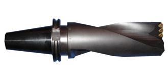
11 Magic Drill DRZ Magic Drill DRZ Magic Drill DRZ With New 5xD Inch-Size Lineup! Single insert in both pockets and four cutting edges per insert promotes cost savings and increased efficiency Molded chipbreaker produces three separate chips for smooth chip evacuation Inserts available in new MEGACOAT PVD coated carbides for a variety of applications Able to offset drill and drill into slant workpieces without pre-drilling Excellent surface finishes Chips are divided into a total of 3 pcs: 2 pcs from the outer edge and 1 pc from the inner edge. Silver Nickel Coating Promotes longer tool life Improves chip flow 5
 Angle A T Ød W r (º) MEGACOAT Uncoated Carbide Carbide ZCMT 050203 0.232 0.094 0.091 0.107 0.012 06T204 0.276 0.110 0.098 0.236 080304 0.381 0.125 0.114 0.323 0.016 10T304 0.473 0.")

 Insert Size ZCMT05 ZCMT06 ZCMT08 Workpiece Chipbreaker Standard SP SU Standard SP SU Standard SP")

12 Magic Drill DRZ Inserts Shape Classification of Usage : 1st Choice : 2nd Choice (Steel; non heat treated) P Carbon Steel / Alloy Steel Mold Steel M Stainless Steel K Cast Iron N Non-Ferrous Metal Dimensions (inch) Angle A T Ød W r (º) MEGACOAT Uncoated Carbide Carbide ZCMT T T T ZCMT SP T204SP SP T304SP T304SP SP PR1230 PR1225 PR1210 KW10 Reference Page for Toolholder 7-18 Magic Drill DRZ ZCMT SU T204SU Insert Grade Features: Page 1 : Stock Standard : World Express Suitable Chipbreaker (ZCMT) Insert Size ZCMT05 ZCMT06 ZCMT08 Workpiece Chipbreaker Standard SP SU Standard SP SU Standard SP Material Cutting Depth 2D 3D 4D 2D 3D 4D 2D 3D 4D 2D 3D 4D 2D 3D 4D 2D 3D 4D 2D 3D 4D 2D 3D 4D Low Carbon Steel Carbon Steel Alloy Steel Mold Steel Stainless Steel Cast Iron Aluminum Alloy Brass Titanium Alloy Insert Size ZCMT10 ZCMT12 ZCMT15 ZCMT20 Workpiece Chipbreaker Standard SP Standard SP Standard SP Standard Material Cutting Depth 2D 3D 4D 5D 2D 3D 4D 5D 2D 3D 4D 5D 2D 3D 4D 5D 2D 3D 4D 5D 2D 3D 4D 5D 2D 3D 4D Low Carbon Steel Carbon Steel Alloy Steel Mold Steel Stainless Steel Cast Iron Aluminum Alloy Brass Titanium Alloy Standard chipbreakers (without symbol) may function better with interrupted cutting. When machining aluminum, chips become long and difficult to discharge at depths over 2D. : 1st Recommendation : 2nd Recommendation Inserts are sold in 10 piece boxes 6
 ØD L1 L2 L3 Ød Ød1 Rc S75 -DRZ5621125-05G 2 0.562 3.87 2.18 1.125 0.75 1.06 Max.")

13 Magic Drill DRZ Inch-Inch (2xD) DRZ (Drilling Depth : 2 x D) Inch Dimension Magic Drill DRZ Toolholder Dimensions Stock No. of Insert When offset machining, reduce feed rate to.003ipr or less See Page 77 for Adjustable Sleeve ASL. Dimension (inch) ØD L1 L2 L3 Ød Ød1 Rc S75 -DRZ G Max. Offset (Radial) Spare Parts Insert Screw Wrench Plug 2D Applicable Inserts Page 6 ZCMT /8 NPT SB-2045TR FT-6 GP-1N ZCMT050203SP ZCMT050203SU S100 -DRZ G DRZ G /8 -DRZ G SB-2260TR DT-7 GP-1N NPT -DRZ G DRZ G DRZ G /8 -DRZ G NPT -DRZ G DRZ G DRZ G / DRZ G NPT DRZ G S125 -DRZ G DRZ G /4 -DRZ G NPT -DRZ G DRZ G DRZ G DRZ G DRZ G /4 -DRZ G NPT -DRZ G DRZ G DRZ G ZCMT06T204 ZCMT06T204SP ZCMT06T204SU SB-2570TR DT-8 GP-1N ZCMT ZCMT080304SP SB-4085TR DT-15 GP-2N ZCMT10T304 ZCMT10T304SP SB-5085TR DT-20 GP-2N ZCMT12T306 ZCMT12T304SP SB-5085TR DT-20 GP-2N ZCMT ZCMT150406SP : Stock Standard : World Express Recommended Cutting Conditions Page 19 7
 ØD L1 L2 L3 Ød Ød1 Rc S75 -DRZ5621687-05G 2 0.562 4.42 2.72 1.687 0.75 1.06 Max.")

14 Inch-Inch (3xD) DRZ (Drilling Depth : 3 x D) Inch Dimension Toolholder Dimensions Stock No. of Insert When offset machining, reduce feed rate to.003ipr or less See Page 77 for Adjustable Sleeve ASL. Dimension (inch) ØD L1 L2 L3 Ød Ød1 Rc S75 -DRZ G Max. Offset (Radial) Spare Parts Insert Screw Wrench Plug 3D Applicable Inserts Page 6 ZCMT /8 NPT SB-2045TR FT-6 GP-1N ZCMT050203SP ZCMT050203SU S100 -DRZ G DRZ G /8 -DRZ G SB-2260TR DT-7 GP-1N NPT -DRZ G DRZ G DRZ G /8 -DRZ G NPT -DRZ G DRZ G DRZ G / DRZ G NPT DRZ G S125 -DRZ G DRZ G /4 -DRZ G NPT -DRZ G DRZ G DRZ G DRZ G DRZ G /4 -DRZ G NPT -DRZ G DRZ G DRZ G ZCMT06T204 ZCMT06T204SP ZCMT06T204SU SB-2570TR DT-8 GP-1N ZCMT ZCMT080304SP SB-4085TR DT-15 GP-2N ZCMT10T304 ZCMT10T304SP SB-5085TR DT-20 GP-2N ZCMT12T306 ZCMT12T304SP SB-5085TR DT-20 GP-2N ZCMT ZCMT150406SP : Stock Standard : World Express Recommended Cutting Conditions Page 19 Magic Drill DRZ 8
15 Magic Drill DRZ Inch-Inch (4xD) DRZ (Drilling Depth : 4 x D) Inch Dimension Magic Drill DRZ Toolholder Dimensions Stock No. of Insert Dimension (inch) ØD L1 L2 L3 Ød Ød1 Rc Max. Offset (Radial) Spare Parts Insert Screw Wrench Plug 4D Applicable Inserts Page 6 S75 -DRZ G When offset machining, reduce feed rate to.002ipr or less See Page 77 for Adjustable Sleeve ASL. 1/8 NPT SB-2045TR FT-6 GP-1N S100 -DRZ G DRZ G / DRZ G NPT SB-2260TR DT-7 GP-1N -DRZ G DRZ G /8 -DRZ G NPT -DRZ G SB-2570TR DT-8 GP-1N S125 -DRZ G DRZ G / DRZ G NPT SB-4085TR DT-15 GP-2N -DRZ G S125 -DRZ G DRZ G /4 -DRZ G NPT -DRZ G SB-5085TR DT-20 GP-2N -DRZ G S125 -DRZ G S150 -DRZ G DRZ G /4 -DRZ G NPT -DRZ G SB-5085TR DT-20 GP-2N -DRZ G DRZ G ZCMT ZCMT050203SP ZCMT050203SU ZCMT06T204 ZCMT06T204SP ZCMT06T204SU ZCMT ZCMT080304SP ZCMT10T304 ZCMT10T304SP ZCMT12T306 ZCMT12T304SP ZCMT ZCMT150406SP : Stock Standard : World Express Recommended Cutting Conditions Page 19 9


16 Inch-Inch (5xD) DRZ (Drilling Depth : 5 x D) Inch Dimension Toolholder Dimensions Stock No. of Insert Dimension (inch) ØD L1 L2 L3 Ød Ød1 Rc Max. Offset (Radial) -DRZ G DRZ G Spare Parts Insert Screw S125 -DRZ G DRZ G / SB-4085TR -DRZ G NPT DRZ G DRZ G / SB-5085TR -DRZ G NPT DRZ G DRZ G S150 -DRZ G DRZ G DRZ G / SB-5085TR -DRZ G NPT DRZ G DRZ G When offset machining, reduce feed rate to.002ipr or less See Page 77 for Adjustable Sleeve ASL. Wrench DT-15 DT-20 DT-20 5D Applicable Inserts Page 6 ZCMT10T304 ZCMT10T304SP ZCMT12T306 ZCMT12T304SP ZCMT ZCMT150406SP : Stock Standard : World Express Recommended Cutting Conditions Page 19 Magic Drill DRZ 10
17 Magic Drill DRZ Metric-Inch (3xD) DRZ (Drilling Depth : 3 x D) Metric Dimension with Inch Shank Magic Drill DRZ Toolholder Dimensions Stock No. of Insert Dimension (inch) ØD L1 L2 L3 Ød Ød1 Rc Max. Offset (Radial) Spare Parts Insert Screw Wrench Plug 3D Applicable Inserts Page 6 S075 -DRZ G -DRZ G -DRZ G -DRZ G (13.0mm) (13.5mm) (14.0mm) (14.5mm) / NPT SB-2045TR FT-6 GP-1N ZCMT ZCMT050203SP ZCMT050203SU -DRZ G (15.0mm) DRZ G (15.5mm) S100 -DRZ G (16.0mm) DRZ G (16.5mm) DRZ G (17.0mm) DRZ G -DRZ G -DRZ G (18.0mm) (18.5mm) (19.0mm) /8 NPT SB-2260TR DT-7 GP-1N ZCMT06T204 ZCMT06T204SP ZCMT06T204SU -DRZ G (19.5mm) DRZ G (20.0mm) DRZ G (21.0mm) DRZ G (21.5mm) DRZ G -DRZ G -DRZ G -DRZ G (22.0mm) (22.0mm) (23.0mm) (24.0mm) /8 NPT SB-2570TR DT-8 GP-1N ZCMT ZCMT080304SP -DRZ G (25.0mm) DRZ G (26.0mm) When offset machining, reduce feed rate to.003ipr or less See Page 77 for Adjustable Sleeve ASL. Recommended Cutting Conditions Page 19 : Stock Standard : World Express
 Spare Parts Insert Screw Wrench Plug Applicable Inserts Page 6 S100 -DRZ2781-10G -DRZ2884-10G -DRZ2987-10G -DRZ3090-10G -DRZ3193-10G -DRZ3296-10G S125 -DRZ3399-12G -DRZ34102-12G")
 6.81 4.49 3.19 1.65 + 0.098 1.102 (28.0mm 6.92 4.60 3.31 1.")
18 Metric-Inch (3xD) DRZ (Drilling Depth : 3 x D) Metric Dimension with Inch Shank Toolholder Dimension Stock No. of Insert Dimension (inch) ØD L1 L2 L3 Ød Ød1 Rc Max. Offset (Radial) Spare Parts Insert Screw Wrench Plug Applicable Inserts Page 6 S100 -DRZ G -DRZ G -DRZ G -DRZ G -DRZ G -DRZ G S125 -DRZ G -DRZ G -DRZ G -DRZ G -DRZ G -DRZ G -DRZ G -DRZ G -DRZ G -DRZ G -DRZ G -DRZ G -DRZ G -DRZ G -DRZ G -DRZ G -DRZ G -DRZ G When offset machining, reduce feed rate to.003ipr or less See Page 77 for Adjustable Sleeve ASL (27.0mm) (28.0mm (29.0mm) 1/ NPT (30.0mm) (31.0mm) (32.0mm) (33.0mm) (34.0mm) (35.0mm) (36.0mm) 1/ NPT (37.0mm) (38.0mm) (39.0mm) (40.0mm) (41.0mm) (42.0mm) (43.0mm) (44.0mm) (45.0mm) 1/ NPT (46.0mm) (47.0mm) (48.0mm) (49.0mm) (50.0mm) SB-4085TR DT-15 GP-1N SB-5085TR DT-20 GP-2N SB-5085TR DT-20 GP-2N ZCMT10T304 ZCMT10T304SP ZCMT12T306 ZCMT12T304SP ZCMT ZCMT150406SP : Stock Standard : World Express Recommended Cutting Conditions Page 19 Magic Drill DRZ 12
19 Magic Drill DRZ Metric-Metric (2xD) DRZ (Drilling Depth : 2 x D) Metric Dimension Magic Drill DRZ 13 Stock No. of Insert Recommended Cutting Conditions Page 19 Dimension (inch) ØD L1 L2 L3 Ød Ød1 Rc Max. Offset (Radial) Spare Parts Insert Screw Wrench Plug Applicable Inserts 2D Page 6 S20 -DRZ ZCMT Rc -DRZ SB-2045TR DT-6 GP-1 ZCMT050203SP 1/8 -DRZ ZCMT050203SU S25 -DRZ DRZ ZCMT06T204 -DRZ Rc SB-2260TR DT-7 GP-1 ZCMT06T204SP -DRZ / ZCMT06T204SU -DRZ DRZ DRZ DRZ Rc ZCMT DRZ SB-2570TR DT-8 GP-1 1/8 ZCMT080304SP -DRZ DRZ S32 -DRZ DRZ DRZ Rc +2.0 ZCMT10T SB-4085TR DT-15 GP-2 -DRZ / ZCMT10T304SP -DRZ DRZ DRZ Rc ZCMT12T SB-5085TR DT-20 GP-2 1/4 ZCMT12T304SP S40 -DRZ DRZ DRZ DRZ Rc +2.2 ZCMT12T SB-5085TR DT-20 GP-2 -DRZ / ZCMT12T304SP -DRZ DRZ DRZ DRZ DRZ DRZ DRZ DRZ DRZ Rc ZCMT DRZ SB-5085TR DT-20 GP-2 1/4 ZCMT150406SP -DRZ DRZ DRZ DRZ DRZ DRZ DRZ DRZ DRZ Rc DRZ / SB-60120TR DT-25 GP-2 ZCMT DRZ DRZ : Stock Standard : World Express
20 Metric-Metric (3xD) DRZ (Drilling Depth : 3 x D) Metric Dimension Stock No. of Insert Dimension (inch) ØD L1 L2 L3 Ød Ød1 Rc Max. Offset (Radial) S20 -DRZ DRZ DRZ Rc DRZ / DRZ DRZ S25 -DRZ DRZ DRZ DRZ DRZ Rc -DRZ /8 -DRZ DRZ DRZ DRZ DRZ DRZ DRZ DRZ DRZ DRZ Rc -DRZ /8 -DRZ DRZ DRZ DRZ DRZ S32 -DRZ DRZ DRZ DRZ DRZ DRZ Rc DRZ / DRZ DRZ DRZ DRZ DRZ DRZ DRZ DRZ DRZ Rc DRZ / DRZ DRZ DRZ When offset machining, reduce feed rate to f=0.08mm/rev (0.003ipr) or less. Recommended Cutting Conditions Page 19 Spare Parts Insert Screw Wrench Plug SB-2045TR FT-6 GP-1 SB-2260TR DT-7 GP-1 SB-2570TR DT-8 GP-1 SB-4085TR DT-15 GP-2 SB-5085TR DT-20 GP-2 Applicable Inserts 3D Page 6 ZCMT ZCMT050203SP ZCMT050203SU ZCMT06T204 ZCMT06T204SP ZCMT06T204SU ZCMT ZCMT080304SP ZCMT10T304 ZCMT10T304SP ZCMT12T306 ZCMT12T304SP : Stock Standard : World Express Magic Drill DRZ 14
21 Magic Drill DRZ Metric-Metric (3xD) DRZ (Drilling Depth : 3 x D) Metric Dimension Stock No. of Insert Dimension (mm) ØD L1 L2 L3 Ød Ød1 Rc Max. Offset (Radial) Spare Parts Insert Screw Wrench Plug Applicable Inserts Page 6 Magic Drill DRZ S40 -DRZ DRZ DRZ DRZ RC DRZ / DRZ DRZ DRZ DRZ DRZ DRZ DRZ DRZ DRZ RC -DRZ /4 -DRZ DRZ DRZ DRZ DRZ DRZ DRZ DRZ DRZ RC DRZ / DRZ DRZ When offset machining, reduce feed rate to f=0.08mm/rev (.003ipr) or less. Recommended Cutting Conditions Page 19 SB-5085TR DT-20 GP-2 ZCMT12T306 ZCMT12T304SP SB-5085TR DT-20 GP-2 ZCMT ZCMT150406SP SB-60120TR DT-20 GP-2 ZCMT : Stock Standard : World Express 15
22 Metric-Metric (4xD) DRZ (Drilling Depth : 4 x D) Metric Dimension Stock No. of Insert Dimension (mm) ØD L1 L2 L3 Ød Ød1 Rc Max. Offset (Radial) S20 -DRZ DRZ DRZ Rc DRZ / DRZ DRZ S25 -DRZ DRZ DRZ DRZ DRZ Rc -DRZ / DRZ DRZ DRZ DRZ DRZ DRZ DRZ DRZ DRZ DRZ Rc -DRZ / DRZ DRZ DRZ DRZ DRZ S32 -DRZ DRZ DRZ DRZ DRZ DRZ Rc DRZ / DRZ DRZ DRZ DRZ DRZ DRZ DRZ DRZ DRZ Rc DRZ / DRZ DRZ DRZ When offset machining, reduce feed rate to f=0.08mm/rev (0.003ipr) or less. Recommended Cutting Conditions Page 19 Spare Parts Insert Screw Wrench Plug SB-2045TR FT-6 GP-1 SB-2260TR DT-7 GP-1 SB-2570TR DT-8 GP-1 SB-4085TR DT-15 GP-2 SB-5085TR DT-20 GP-2 Applicable Inserts 4D Page 6 ZCMT ZCMT050203SP ZCMT050203SU ZCMT06T204 ZCMT06T204SP ZCMT06T204SU ZCMT ZCMT080304SP ZCMT10T304 ZCMT10T304SP ZCMT12T306 ZCMT12T304SP : Stock Standard : World Express Magic Drill DRZ 16
23 Magic Drill DRZ Metric-Metric (4xD) DRZ (Drilling Depth : 4 x D) Metric Dimension Magic Drill DRZ Stock No. of Insert Dimension (mm) ØD L1 L2 L3 Ød Ød1 Rc Max. Offset (Radial) Spare Parts Insert Screw Wrench Plug 4D Applicable Inserts Page 6 S40 -DRZ DRZ DRZ DRZ Rc1/4 -DRZ SB-5085TR DT-20 GP-2 ZCMT12T306 ZCMT12T304SP -DRZ DRZ DRZ DRZ DRZ DRZ DRZ DRZ Rc1/4 -DRZ SB-5085TR DT-20 GP-2 ZCMT ZCMT150406SP -DRZ DRZ DRZ DRZ When offset machining, reduce feed rate to f=0.08mm/rev (0.003ipr) or less. Recommended Cutting Conditions Page 19 : Stock Standard : World Express 17
 +2.5 -DRZ28140-10 28 232 173 140 42 +2.2 -DRZ29145-10 2 29 237 178 145 32 +2.0 -DRZ30150-10 30 241 182 150 +1.")


24 Metric-Metric (5xD) DRZ (Drilling Depth : 5 x D) Metric Dimension S32 -DRZ Stock No. of Insert Dimension (mm) ØD L1 L2 L3 Ød Ød1 Rc Max. Offset (Radial) DRZ DRZ DRZ DRZ S40 -DRZ DRZ DRZ Rc1/ DRZ DRZ DRZ DRZ DRZ DRZ DRZ Recommended Cutting Conditions Page 19 Spare Parts Insert Screw Wrench Plug SB-4085TR DT-15 GP-2 SB-5085TR DT-20 GP-2 Applicable Inserts 5D Page 6 ZCMT10T304 ZCMT10T304SP ZCMT12T306 ZCMT12T304SP ZCMT ZCMT150406SP : Stock Standard : World Express Magic Drill DRZ 18
25 Magic Drill DRZ Magic Drill DRZ DRZ Recommended Cutting Conditions (Coolant) Workpiece Material Low Carbon Steel Carbon Steel Recommended Insert Grades (Cutting Speed Vc: sfm) MEGACOAT PVD Coated Carbide Carbide PR1230 PR1225 PR1210 PR660 PR830 PR915 PR1025 PR930 PR905 KW10 Standard SP SU Standard SP SU 400~ ~ ~ ~600 Alloy Steel 325~ ~525 Mold Steel 250~ ~500 Stainless Steel (Austenitic related) Gray Cast Iron Nodular Cast Iron Nonferrous Metals Titanium Alloys 230~ ~ Apply a sufficient amount of coolant. Standard ~ ~400 Standard SP SU 400~ ~ ~ ~ ~400 Standard SP 400~ ~ ~ ~ ~460 Standard 400~ ~ ~ ~ ~460 Standard SP SU 400~ ~ ~ ~ ~400 Standard SP 400~ ~ ~ ~ ~ Standard Standard SP Cutting Diameter ØDc (inch) Holder Type ( Cutting Depth ) 2D 3D 4D 5D f (ipr) Ø0.512~Ø ~ ~ ~.0032 Ø0.630~Ø ~ ~ ~.0047 Ø1.063~Ø ~ ~ ~ ~.0035 Ø1.969~.0032~ ~ ~.0047 Ø0.512~Ø ~ ~ ~.0032 Ø0.630~Ø ~ ~ ~.0047 Ø1.063~Ø ~ ~ ~ ~.0035 Ø1.969~.0032~ ~ ~.0047 Ø0.512~Ø ~ ~ ~.0032 Ø0.630~Ø ~ ~ ~.0047 Ø1.063~Ø ~ ~ ~ ~.0035 Ø1.969~.0032~ ~ ~.0047 Ø0.512~Ø ~ ~ ~.0028 Ø0.630~Ø ~ ~ ~.0032 Ø1.063~Ø ~ ~ ~ ~.0028 Ø1.969~.0032~ ~ ~.0039 Ø0.512~Ø ~ ~ ~.0024 Ø0.630~Ø ~ ~ ~.0032 Ø1.063~Ø ~ ~ ~ ~.0028 Ø1.969~.0024~ ~ ~.0032 Ø0.512~Ø ~ ~ ~.0032 Ø0.630~Ø ~ ~ ~ ~ ~400 Ø1.063~Ø ~ ~ ~ ~.0039 Ø1.969~.0039~ ~ ~.0059 Ø0.512~Ø ~ ~ ~.0032 Ø0.630~Ø ~ ~ ~ ~ ~325 Ø1.063~Ø ~ ~ ~ ~ ~ ~230 Ø1.969~.0039~ ~ ~.0059 Ø0.512~Ø ~ ~ ~.0032 Ø0.630~Ø ~ ~ ~.0059 Ø1.063~Ø ~ ~ ~ ~.0039 Ø1.969~.0032~ ~ ~.0059 Ø0.512~Ø ~ ~ ~.0024 Ø0.630~Ø ~ ~ ~.0028 Ø1.063~Ø ~ ~ ~ ~.0020 Ø1.969~.0024~ ~ ~ st Recommendation : 2nd Recommendation 19
26 Cutting Conditions by Application (Work Material : 1050) Application Plain Surface Slant Surface Half Cylindrical Hole Expansion Concave Surface Pre-drilled Surface Stacked Plates Workpiece Shape DRS DRZ SFM f (ipr) Not Recommended Not Recommended Not Recommended Not Recommended 270 Concave Part Continuous Part SFM Concave Part f (ipr) Continuous Part Coolant Yes Yes Yes Yes Yes - - Magic Drill DRX 20


: ZXMT06T204SM (PR1225) 21 MEGACOAT Coating")
27 Magic Drill DRX Magic Drill DRX New 5xD inch-size offering Magic Drill DRX Twisted coolant hole technology for improved chip evacuation Three chipbreakers for a variety of workpiece materials MEGACOAT insert grades cover a variety of applications Balanced cutting system for precision drilling and excellent surface finishes Twisted Coolant Hole technology design provides Superior Chip Evacuation Outer edge The flute space of the internal cutting edge side is 1.6 times larger than the DRZ style drill, providing increased chip evacuation The coolant performance has 1.25 times more volume than the DRZ style drill Inner edge Double coolant hole Outer edge The special alloy provides tool holder rigidity and increased reliability Inner edge Conventional tools Single coolant hole Three New MEGACOAT Insert Grades (PR1230: for Steel, PR1225: for Stainless Steel / Low Carbon Steel, PR1210: for Cast Iron) Vc=150 m/min, f=0.1 mm/rev., Dc=ø20, H=35 mm, WET, X5CrNi18 10 (SUS304): ZXMT06T204SM (PR1225) 21 MEGACOAT Coating Technology provides longer and more stable tool life Wear comparison MEGACOAT achieves better wear resistance than competitor B achieving longer tool life
, ø20-3d, WET, C45 (S45C), NC Lathe Vc=400 sfm, f=0.004 ipr., H=0.")

, ø14-4d, WET, C50 Compared to competitor F, the DRX's excellent chip")

 Produces small chips for better evacuation Produces continuous")
 s-shaped outer cutting edge sharp cutting Horizontal force")

28 Balanced Cutting System Vibration comparison Surface finish comparison Vc=600 sfm, f=0.006 ipr, H=2.4" (through hole), ø20-3d, WET, C45 (S45C), NC Lathe Vc=400 sfm, f=0.004 ipr., H=0.6", ø20-3d, WET, C55 (S55C) DRX Competitor D Less vibration due to balanced cutting system Better surface finish Variation of drilling diameter Competitor E Better surface finish than Competiror D and E Vc=180m/min, f=0.08mm/rev., H=56mm (blind hole), ø14-4d, WET, C50 Compared to competitor F, the DRX's excellent chip evacuation performance provides good balance and less variation in cutting dia. drastically improving straight machining capability Magic Drill DRX New chipbreaker design covers a variety of workplace materials New chipbreaker features Wider chipbreaker (outer edge) Flat chipbreaker (inner edge) Produces small chips for better evacuation Produces continuous chips (ideal) S-shaped cutting edge (outer edge) Vc=120m/min, f=0.1mm/rev., H=15mm, ø20-3d, WET, C55 (S55C) s-shaped outer cutting edge sharp cutting Horizontal force (N) DRX Horizontal force (N) Competitor G Cutting force comparison of outer edge at the start of drilling Lowered impact force at the start Reduces sudden breakage 22
29 Magic Drill DRX Chipbreaker Selection P (Carbon Steel, Alloy Steel) M (Stainless Steel) K (Cast Iron) Magic Drill DRX Low Carbon Steel Midium~High Carbon Steel non heat treated no interruption heat treated (Hard Materials) with interruption low~medium feed rate medium~high feed rate SM SM GM GH SM GM PR1225 PR1225 PR1230 PR1230 PR1225 PR

 Magic Drill DRX Cutting edge strength oriented design Cutting edge strength oriented design of chipbreaker Wider chipbreaker control breakage by pressed chips")

30 Three chipbreakers for a variety of materials GM Chipbreaker General Cutting For Steel: PR1230 For Cast Iron: PR1210 Wider chipbreaker can cover a variety of materials For general cutting Achieves good balance of cutting edge strength and sharp cutting GH Chipbreaker Tough Edge 1st recommended chipbreaker for hard materials & interrupted operations Optimized cutting edge strength, sharpness and chip control For hard materials, interrupted machining: PR1230 Chipping resistance comparison Vc=260 sfm, f=0.003 ipr, H=0.39", Dc=ø0.79", 3D type, WET, C50 (S50C) Magic Drill DRX Cutting edge strength oriented design Cutting edge strength oriented design of chipbreaker Wider chipbreaker control breakage by pressed chips Interrupted drilling by displacing center of hole by 8mm Competitor G Competitor H Conventional tool Number of holes Better chipping resistance than competitors SM Chipbreaker Sharp Cutting for Deeper Drilling For Stainless Steel, Low Carbon Steel: PR1225 For deep drilling of difficult to control chips materials such as stainless steel and low carbon steel Sharp cutting by large rake angle Stable chip control by newly designed chipbreaker and U-shaped cutting edge Sharp cutting by large rake angle U-shaped cutting edge breaks chips by growing cracks from both ends Outstanding chip control achieved by splitting chips from the outer edges Chip breaking system of SM chipbreaker (Outer edge) 24
 Carbon steel / Alloy steel P Mold Steel M")


31 Magic Drill DRX Magic Drill DRX Inserts Magic Drill DRX Insert Classification of Usage : 1st Choice : 2nd Choice (Steel; non heat treated) Carbon steel / Alloy steel P Mold Steel M Stainless Steel K Cast Iron N Non-ferrous Metals Dimension (mm) Angle ( ) MEGACOAT A T ød W r ZXMT GM-E PR1230 PR1225 PR1210 Carbide GW15 Reference Page for Toolholder For outer edge For inner edge ZXMT GM-I ZXMT GH-E For outer edge ZXMT SM-E For outer edge Insert Grade Features Page 1 ZXMT GM T203GM T204GM GM T306GM T306GM GM GM ZXMT GH T203GH T204GH GH T306GH T306GH GH GH ZXMT SM T203SM T204SM SM T306SM T306SM SM SM Page : Stock Standard : World Express

 1) For outer edge, please select -E insert from three different chipbreakers for each application. 2) For inner edge, please select -I insert (GM chipbreaker only).")
32 Suitable Chipbreaker (ZXMT) Workpiece Material Insert Type Advantages of the Chipbreaker Chipbreaker GM GH SM Insert Advantages ZXMT type Chipbreaker GM GH SM Cutting Depth 2D 3D 4D 5D 2D 3D 4D 5D 2D 3D 4D 5D Low Carbon Steel Carbon steel Alloy Steel Mold steel Stainless Steel Cast Iron Aluminum Alloys Brass Titanium Alloys : 1st Recommendation : 2nd Recommendation 1st. recommendation for carbon steel and alloy steel, 1st. recommendation for cast iron. Good balance of sharp cutting and cutting edge strength How to select ZXMT03 ZXMT03 type (Cutting Dia.: Ø12~Ø13) 1) For outer edge, please select -E insert from three different chipbreakers for each application. 2) For inner edge, please select -I insert (GM chipbreaker only). Outer edge ZXMT E GM-E GH-E SM-E 1st. recommendation for interrupted machining and hard materials. Cutting edge strength oriented design. Middle to high feed rates of steel machining, GM Chipbreaker alternative Inner Edge ZXMT030203GM-I GM-I Suitable for sticky materials such as stainless steel and low carbon steel Sharp cutting, prevents chattering. For low to medium feed rates of steel. Magic Drill DRX Outer edge Wide chipbreaker Chipbreaker Cross-section Chips from Outer edge Inner edge Flat chipbreaker Chipbreaker Cross-section Chips from Inner edge Workpiece Material S50C S50C SUS304 Indication of tool life of Magic Drill How to judge tool life Indication of judging tool life Judgement of tool condition and insert wear Checking cutting diameter Checking the surface on the exit side Variation of cutting noise Variation of vibration When an insert is new the holder is slightly bent to the side during cutting. (Therefore, the cutting diameter is slightly bigger during cutting). Once cutting is finished, the holder will return back to normal size. No tool marks will appear on the finished surface. (Although this depends on workpiece and cutting condition: during external machining slight tool mark might appear.) When an insert is at the end of its tool life, Gradually the external corner part gets worn out, the holder does not bend slightly outwards - it starts to bend inwards. After the cutting is finished, the holder returns to the normal position. When taking off a holder under this condition the cutting edge of the insert creates external tool marks on the finished surface of the workpiece. When cutting diameter is measured, suddenly it shows small diameter. In this case, a worn out insert can be the cause. If insert wear progresses, the burrs of penetrated hole entrance becomes bigger. This is a clear indication that the tool must be exchanged. Light cutting noise at the beginning turns to brady noise which contains vibration noise. As the end of tool life is getting closer, there is more vibration and the cutting noise changes. However, when machining smaller diameters these factors are difficult to detect. 26
33 Magic Drill DRX Inch-Inch (5xD) DRX (Drilling Depth : 5 x D) Inch Diameter Magic Drill DRX Toolholder Dimensions Stock No. of insert Dimension (mm) ØDc L1 L2 L3 Ød Ød1 Max. Offset (Radial) (mm) Spare Parts Insert Screw Wrench 5D Applicable Insert Page 25 S075 -DRX SB-2042TRG DTM-6 ZXMT S100 -DRX DRX DRX DRX DRX DRX DRX DRX DRX DRX When offset machining, reduce feed rate to.002ipr or less See Page 77 for Adjustable Sleeve SHE. SB-2045TR DTM-6 ZXMT05T203 SB-2250TR DTM-7 ZXMT06T204 SB-2570TR DTM-8 ZXMT : Stock Standard : World Express Recommended Cutting Conditions Page 35 27
 (mm) S20 -DRX120M-2-03 12 88 45 24 +0.5 -DRX125M-2-03 2 12.5 89 46 25 20 27 +0.4 -DRX130M-2-03 13 90 47 26 +0.3 S20 -DRX135M-2-04 13.5 91 48 27 +0.5 -DRX140M-2-04 14 92 49 28 +0.")
34 Metric-Metric (2xD) DRX (Drilling Depth : 2 x D) Metric Diameter Toolholder Dimensions Stock No. of insert Dimension (mm) ØDc L1 L2 L3 Ød Ød1 Max. Offset (Radial) (mm) S20 -DRX120M DRX125M DRX130M S20 -DRX135M DRX140M DRX145M DRX150M S25 -DRX155M DRX160M DRX165M DRX170M DRX175M DRX180M DRX185M DRX190M DRX195M DRX200M DRX205M DRX210M DRX215M DRX220M DRX225M DRX230M DRX235M DRX240M DRX245M DRX250M DRX255M DRX260M S32 -DRX270M DRX280M DRX290M DRX300M DRX310M S40 -DRX320M DRX330M DRX340M DRX350M DRX360M DRX370M DRX380M When offset machining, reduce feed rate to.003ipr or less See Page 77 for Adjustable Sleeve SHE. Spare Parts Insert Screw SB-2042TRG Wrench DTM-6 2D Applicable Insert Page 25 ZXMT E (External) ZXMT030203GM-I (Internal) SB-2042TRG DTM-6 ZXMT SB-2045TR DTM-6 ZXMT05T203 SB-2250TR DTM-7 ZXMT06T204 SB-2570TR DTM-8 ZXMT SB-3080TR DTM-10 ZXMT09T306 SB-4085TR DTM-15 ZXMT11T306 : Stock Standard : World Express Recommended Cutting Conditions Page 35 Magic Drill DRX 28
35 Magic Drill DRX Metric-Metric (2xD) Toolholder Dimensions Stock No. of insert Dimension (mm) ØDc L1 L2 L3 Ød Ød1 Max. Offset (Radial) (mm) Spare Parts Insert Screw Wrench Applicable Insert Page 25 Magic Drill DRX S40 -DRX390M DRX400M DRX410M DRX420M DRX430M DRX440M DRX450M DRX460M DRX470M S40 -DRX480M DRX490M DRX500M DRX510M DRX520M DRX530M DRX540M DRX550M DRX560M DRX570M DRX580M DRX590M DRX600M When offset machining, reduce feed rate to.003ipr or less See Page 77 for Adjustable Sleeve SHE. Cutting Tolerance (2D Type) SB-5090TR DT-20 ZXMT SB-60120TR DT-25 ZXMT : Stock Standard : World Express Recommended Cutting Conditions Page 35 Dc Cutting Tolerance (mm) Dc Cutting Tolerance (mm) Dc Cutting Tolerance (mm) Ø12~Ø26 Ø27~Ø38 Ø39~Ø Listed tolerance is guideline numbers. These guideline numbers may be variable depending on machines, workpieces, clamping conditions and cutting conditions. Magic Drill (DRX) Hole Bottom Shape (Available for 2xD, 3xD, 4xD and 5xD type) (mm) 29 ØDc A B C ØDc A B C ØDc A B C Chart above is for 2xD, 3xD, 4xD, and 5xD drills Figure above are nominal sizes (Varies from '' to '' depending on work material and cutting conditions) A B ØDc C
 (mm) S20 -DRX120M-3-03 12 100 57 36 +0.5 -DRX125M-3-03 2 12.5 102 59 37.5 20 27 +0.4 -DRX130M-3-03 13 103 60 39 +0.3 S20 -DRX135M-3-04 13.5 105 62 40.5 +0.")

36 Metric-Metric (3xD) DRX (Drilling Depth : 3 x D) Metric Diameter Toolholder Dimensions Stock No. of insert Dimension (mm) ØDc L1 L2 L3 Ød Ød1 Max. Offset (Radial) (mm) S20 -DRX120M DRX125M DRX130M S20 -DRX135M DRX140M DRX145M DRX150M S25 -DRX155M DRX160M DRX165M DRX170M DRX175M DRX180M DRX185M DRX190M DRX195M DRX200M DRX205M DRX210M DRX215M DRX220M DRX225M DRX230M DRX235M DRX240M DRX245M DRX250M DRX255M DRX260M S32 -DRX265M DRX270M DRX275M DRX280M DRX285M DRX290M DRX295M DRX300M DRX305M DRX310M DRX315M S40 -DRX320M DRX330M DRX340M DRX350M DRX360M DRX370M DRX380M When offset machining, reduce feed rate to.003ipr or less See Page 77 for Adjustable Sleeve SHE. Spare Parts Insert Screw SB-2042TRG Wrench DTM-6 3D Applicable Insert Page 25 ZXMT030203ss-E (External) ZXMT030203GM-I (Internal) SB-2042TRG DTM-6 ZXMT SB-2045TR DTM-6 ZXMT05T203 SB-2250TR DTM-7 ZXMT06T204 SB-2570TR DTM-8 ZXMT SB-3080TR DTM-10 ZXMT09T306 SB-4085TR DTM-15 ZXMT11T306 : Stock Standard : World Express Recommended Cutting Conditions Page 35 Magic Drill DRX 30
37 Magic Drill DRX Metric-Metric (3xD) Toolholder Dimensions Stock No. of insert Dimension (mm) ØDc L1 L2 L3 Ød Ød1 Max. Offset (Radial) (mm) Spare Parts Insert Screw Wrench Applicable Insert Page 25 Magic Drill DRX S40 -DRX390M DRX400M DRX410M DRX420M DRX430M DRX440M DRX450M DRX460M DRX470M S40 -DRX480M DRX490M DRX500M DRX510M DRX520M DRX530M DRX540M DRX550M DRX560M DRX570M DRX580M DRX590M DRX600M When offset machining, reduce feed rate to.003ipr or less See Page 77 for Adjustable Sleeve SHE. SB-5090TR DT-20 ZXMT SB-60120TR DT-25 ZXMT : Stock Standard : World Express Recommended Cutting Conditions Page 35 Cutting Tolerance (3D Type) Dc Ø12~Ø26 Ø26.5~Ø38 Ø39~Ø60 Cutting Tolerance (mm) Listed tolerance is guideline numbers. These guideline numbers may be variable depending on machines, workpieces, clamping conditions and cutting conditions. 31
 (mm) S20 -DRX120M-4-03 12 112 69 48 +0.5 -DRX125M-4-03 2 12.5 114 71 50 20 27 +0.4 -DRX130M-4-03 13 116 73 52 +0.3 S20 -DRX135M-4-04 13.5 118 75 54 +0.5 -DRX140M-4-04 14 120 77 56 +0.")

38 Metric-Metric (4xD) DRX (Drilling Depth : 4 x D) Metric Diameter Toolholder Dimensions Stock No. of insert Dimension (mm) ØDc L1 L2 L3 Ød Ød1 Max. Offset (Radial) (mm) S20 -DRX120M DRX125M DRX130M S20 -DRX135M DRX140M DRX145M DRX150M S25 -DRX155M DRX160M DRX165M DRX170M DRX175M DRX180M DRX185M DRX190M DRX195M DRX200M DRX205M DRX210M DRX215M DRX220M DRX225M DRX230M DRX235M DRX240M DRX245M DRX250M DRX255M DRX260M S32 -DRX270M DRX280M DRX290M DRX300M DRX310M S40 -DRX320M DRX330M DRX340M DRX350M DRX360M DRX370M DRX380M When offset machining, reduce feed rate to.002ipr or less See Page 77 for Adjustable Sleeve SHE. Spare Parts Insert Screw SB-2042TRG Wrench DTM-6 4D Applicable Insert Page 25 ZXMT E (External) ZXMT030203GM-I (Internal) SB-2042TRG DTM-6 ZXMT SB-2045TR DTM-6 ZXMT05T203 SB-2250TR DTM-7 ZXMT06T204 SB-2570TR DTM-8 ZXMT SB-3080TR DTM-10 ZXMT09T306 SB-4085TR DTM-15 ZXMT11T306 : Stock Standard : World Express Recommended Cutting Conditions Page 35 Magic Drill DRX 32
39 Magic Drill DRX Metric-Metric (4xD) Toolholder Dimensions Stock No. of insert Dimension (mm) ØDc L1 L2 L3 Ød Ød1 Max. Offset (Radial) (mm) Spare Parts Insert Screw Wrench Applicable Insert Page 25 Magic Drill DRX S40 -DRX390M DRX400M DRX410M DRX420M DRX430M DRX440M DRX450M DRX460M DRX470M S50 -DRX480M DRX490M DRX500M DRX510M DRX520M DRX530M DRX540M DRX550M DRX560M DRX570M DRX580M DRX590M DRX600M When offset machining, reduce feed rate to.002ipr or less See Page 77 for Adjustable Sleeve SHE. DRX Cutting Tolerance (3D Type) Dc Cutting Tolerance (mm) Ø12~Ø Ø27~Ø Ø39~Ø Listed tolerance is guideline numbers. These guideline numbers may be variable depending on machines, workpieces, clamping conditions and cutting conditions. SB-5090TR DT-20 ZXMT SB-60120TR DT-25 ZXMT : Stock Standard : World Express Recommended Cutting Conditions Page 35 DRX Cutting Tolerance (5D Type) Dc Ø14~Ø26 Cutting Tolerance (mm) Dc Cutting Tolerance (mm) Dc Cutting Tolerance (mm) Ø27~Ø38 Ø39~Ø Listed tolerance is guideline numbers. These guideline numbers may be variable depending on machines, workpieces, clamping conditions and cutting conditions. 33
 (mm) S20 -DRX140M-5-04 14 134 91 70 +0.4 2 20 27 -DRX150M-5-04 15 139 96 75 +0.2 S25 -DRX160M-5-05 16 158 103 80 +0.7 -DRX170M-5-05 2 17 163 108 85 25 32 +0.")

40 Metric-Metric (5xD) DRX (Drilling Depth : 5 x D) Metric Diameter Toolholder Dimensions Stock No. of insert Dimension (mm) ØDc L1 L2 L3 Ød Ød1 Max. Offset (Radial) (mm) S20 -DRX140M DRX150M S25 -DRX160M DRX170M DRX180M DRX190M DRX200M DRX210M DRX220M DRX230M DRX240M DRX250M DRX260M S32 -DRX270M DRX280M DRX290M DRX300M DRX310M S40 -DRX320M DRX330M DRX340M DRX350M DRX360M DRX370M DRX380M DRX390M DRX400M DRX410M DRX420M DRX430M DRX440M DRX450M DRX460M DRX470M S50 -DRX480M DRX490M DRX500M DRX510M DRX520M DRX530M DRX540M DRX550M DRX560M DRX570M DRX580M DRX590M DRX600M When offset machining, reduce feed rate to.002ipr or less See Page 77 for Adjustable Sleeve SHE. Spare Parts Insert Screw Wrench 5D Applicable Insert Page 25 SB-2042TRG DTM-6 ZXMT SB-2045TR DTM-6 ZXMT05T203 SB-2250TR DTM-7 ZXMT06T204 SB-2570TR DTM-8 ZXMT SB-3080TR DTM-10 ZXMT09T306 SB-4085TR DTM-15 ZXMT11T306 SB-5090TR DT-20 ZXMT SB-60120TR DT-25 ZXMT Magic Drill DRX : Stock Standard : World Express 34 Recommended Cutting Conditions Page 35
41 Magic Drill DRX Magic Drill DRX Magic Drill DRX Recommended Cutting Conditions (Coolant) Workpiece Material Low Carbon Steel Carbon Steel Recommended Cutting Speed (SFM) Type (Drilling Depth) PVD Coated Carbide Cutting Dia. PR1230 PR1225 PR1210 GW15 ØDc 2D~3D 4D 5D GM (inch) Feed Rate (ipr) SM GM SM GH GM GH SM GM GH SM GM GH SM 400 ~ ~ ~ ~ 600 Alloy Steel 330 ~ ~ 530 Tool Steel 270 ~ ~ 500 Stainless Steel Gray Cast Iron Nodular Cast Iron (Ductile) Non-Ferrous Metal Titanium Alloy 240 ~ ~ ~ ~ ~ ~ 240 Ø 0.432~ Ø ~ ~ ~ ~ ~ ~ ~ ~ ~.0031 Ø 0.630~ Ø ~ ~ ~ ~ ~ ~ ~ ~ ~.0039 Ø 0.748~ Ø ~ ~ ~ ~ ~ ~ ~ ~ ~.0047 Ø 1.063~ Ø ~ ~ ~ ~ ~ ~ ~ ~ ~.0047 Ø 0.432~ Ø ~ ~ ~ ~ ~ ~ ~ ~ ~.0031 Ø 0.630~ Ø ~ ~ ~ ~ ~ ~ ~ ~ ~.0039 Ø 0.748~ Ø ~ ~ ~ ~ ~ ~ ~ ~ ~.0047 Ø 1.063~ Ø ~ ~ ~ ~ ~ ~ ~ ~ ~.0047 Ø 0.432~ Ø ~ ~ ~ ~ ~ ~ ~ ~ ~.0031 Ø 0.630~ Ø ~ ~ ~ ~ ~ ~ ~ ~ ~.0039 Ø 0.748~ Ø ~ ~ ~ ~ ~ ~ ~ ~ ~.0047 Ø 1.063~ Ø ~ ~ ~ ~ ~ ~ ~ ~ ~.0047 Ø 0.432~ Ø ~ ~ ~ ~ ~ ~ ~ ~ ~.0028 Ø 0.630~ Ø ~ ~ ~ ~ ~ ~ ~ ~ ~.0031 Ø 0.748~ Ø ~ ~ ~ ~ ~ ~ ~ ~ ~.0039 Ø 1.063~ Ø ~ ~ ~ ~ ~ ~ ~ ~ ~.0039 Ø 0.432~ Ø ~ ~ ~ ~ ~ ~ ~ ~ ~.0031 Ø 0.630~ Ø ~ ~ ~ ~ ~ ~ ~ ~ ~.0043 Ø 0.748~ Ø ~ ~ ~ ~ ~ ~ ~ ~ ~.0047 Ø 1.063~ Ø ~ ~ ~ ~ ~ ~ ~ ~ ~.0047 Ø 0.432~ Ø ~.0055 ~ ~.0024 ~.0047 ~ ~.0016 ~.0039 ~ ~ Ø 0.630~ Ø ~.0071 ~ ~.0031 ~.0063 ~ ~.0024 ~.0047 ~ ~ Ø 0.748~ Ø ~.0079 ~ ~.0031 ~.0071 ~ ~.0024 ~.0055 ~ ~ Ø 1.063~ Ø ~.0079 ~ ~.0031 ~.0071 ~ ~.0024 ~.0055 ~ ~ Ø 0.432~ Ø ~.0047 ~ ~.0024 ~.0039 ~ ~.0016 ~.0031 ~ ~ Ø 0.630~ Ø ~.0063 ~ ~.0031 ~.0055 ~ ~.0024 ~.0039 ~ ~ Ø 0.748~ Ø ~.0071 ~ ~.0031 ~.0063 ~ ~.0024 ~.0047 ~ ~ Ø 1.063~ Ø ~.0071 ~ ~.0031 ~.0063 ~ ~.0024 ~.0047 ~ ~ Ø 0.432~ Ø ~ ~.0024 ~.0047 ~ ~.0020 ~.0039 ~ ~.0016 ~.0031 Ø 0.630~ Ø ~ ~.0031 ~.0055 ~ ~.0024 ~.0047 ~ ~.0020 ~.0039 Ø 0.748~ Ø ~ ~.0031 ~.0063 ~ ~.0024 ~.0055 ~ ~.0020 ~.0047 Ø 1.063~ Ø ~ ~.0031 ~.0079 ~ ~.0031 ~.0063 ~ ~.0028 ~.0055 Ø 0.432~ Ø ~ ~.0020 ~.0031 ~ ~.0016 ~.0028 ~ ~.0016 ~.0024 Ø 0.630~ Ø ~ ~.0020 ~.0031 ~ ~.0016 ~.0028 ~ ~.0016 ~.0024 Ø 0.748~ Ø ~ ~.0024 ~.0039 ~ ~.0024 ~.0031 ~ ~.0020 ~.0028 Ø 1.063~ Ø ~ ~.0024 ~.0039 ~ ~.0024 ~.0031 ~ ~.0020 ~.0028 Apply sufficient amount of coolant : 1st Recommendation : 2nd Recommendation Cutting Conditions by Application Application Plain Surface Slant Surface Half Clindical Hole Expansion Concave Surface Pre-drilled Surface Stacked Plates Workpiece Shape DRX Cutting Speed (SFM) Feed Rate (ipr) Concave Part.002 Continuous Part.004 See Coremaster Coredrill Page 61 See Holeshot Drill Page 53 Coolant Yes Yes Yes Yes Yes Yes - 35
42 Recommended Chipbreakers (ZXMT) How to select ZXMT03 Workpiece Material Insert ZXMT type Chipbreaker GM GH SM Cutting Depth 2D 3D 4D 5D 2D 3D 4D 5D 2D 3D 4D 5D ZXMT03 type (Cutting Dia : ø12 ~ ø13) 1) For outer edge, please select "-E" insert from three different chipbreakers for each application. 2) For inner edge, please select "-I" insert (GM chipbreaker only). Low-carbon Steel Carbon Steel Outer edge Inner Edge Alloy Steel Mold Steel Stainless Steel Cast Iron Aluminum Alloys Brass Titanium Alloys : 1st Recommendation : 2nd Recommendation ZXMT E GM-E GH-E SM-E ZXMT030203GM-I GM-I Magic Drill DRX Features of the Magic Drill DRX Chipbreakers Chipbreaker GM GH SM Insert Advantages 1st. recommendation for carbon steel and alloy steel,1st. recommendation for cast iron. Good balance of sharp cutting and cutting edge strength. 1st. recommendation for interrupted machining and hard materials. Cutting edge strength oriented design. Middle to high feed rates of steel machining, GM Chipbreaker alternative. Suitable for sticky materials such as stainless steel and low carbon steel Sharp cutting, prevents chattering. For low to medium feed rates of steel. Outer edge Wide chipbreaker Chips from Outer edge Inner edge Flat chipbreaker Crosssection Crosssection Chips from Inner edge Workpiece Materials C50 (S50C) C50 (S50C) X5CrNi18 10 (SUS304) 36
 Machining depths 3D,5D,8D Magic Drill DRC Straight Shank DRC SS-DRC Flanged Shank DRC SF-DRC Straight Shank DRC with")


43 Magic Drill DRC Magic Drill DRC Machining diameters Ø7.94-Ø20.99 mm (Ø.3125~Ø.8264 in) Machining depths 3D,5D,8D Magic Drill DRC Straight Shank DRC SS-DRC Flanged Shank DRC SF-DRC Straight Shank DRC with Chamfering attachment Please refer to Page 43 and Page 44 for details on the chamfering attachment High efficiency High feed rate High reliability High quality Four unique characteristics of the DRC Magic Drill improve productivity and reduce costs through high speed and high feed rate machining. 1.Self-Clamping design The clamp rigidity and resistance of the DRC Magic Drill's self-clamping method has significantly improved with the new design analysis and material technology. Easy replacement is possible on the machine. 2.Self-Centering design The S-curve top shape geometry of the insert known as the Self-Centering design enables smooth drilling, lowers cutting forces and produces a high quality surface finish. Self-Centering design Insert Straight cutting edge and stable corner edge Binding stability Coolant hole 3.Multiple Helical Angle Flute design Provides superior drill body stiffness and chip evacuation. 4.Direct Cooling design The coolant is fed directly into the inserts cutting face, cooling the top of the drill and preventing chip adhesion, which allows for quick and smooth chip evacuation. 37
 ØDc (inch) Dimensions (inch) ØDc (mm) Lp (inch) PVD Coated PR0315 DC0794M-SC.")

44 Insert Identification System for the Magic Drill DRC Drilling Inserts for DRC Insert ØDc.3125 ~ ~ ~.8264 k8 tolerance k8(inch) k8 is the dimension tolerance of the insert. It is not the dimension tolerance of the cutting diameter. (ISO) ØDc (inch) Dimensions (inch) ØDc (mm) Lp (inch) PVD Coated PR0315 DC0794M-SC DC0800M-SC DC0810M-SC DC0820M-SC DC0830M-SC DC0840M-SC DC0850M-SC DC0860M-SC DC0870M-SC DC0880M-SC DC0890M-SC DC0900M-SC DC0910M-SC DC0920M-SC DC0930M-SC DC0940M-SC DC0950M-SC DC0960M-SC DC0970M-SC DC0980M-SC DC0990M-SC DC1000M-SC DC1010M-SC DC1020M-SC DC1030M-SC DC1040M-SC DC1050M-SC DC1060M-SC DC1070M-SC DC1080M-SC DC1090M-SC DC1100M-SC DC1110M-SC DC1120M-SC DC1130M-SC DC1140M-SC DC1150M-SC DC1160M-SC DC1170M-SC DC1180M-SC DC1190M-SC Applicable Toolholder Page SS10-DRC080M- SF12-DRC080M- SS10-DRC085M- SF12-DRC085M- SS10-DRC090M- SF12-DRC090M- SS10-DRC095M- SF12-DRC095M- SS12-DRC100M- SF16-DRC100M- SS12-DRC105M- SF16-DRC105M- SS12-DRC110M- SF16-DRC110M- SS12-DRC115M- SF16-DRC115M- Magic Drill DRC DC inserts are sold in 1 piece boxes. : Stock Standard : World Express 38
45 Magic Drill DRC Drilling Inserts for DRC Insert (ISO) ØDc (inch) Dimensions (inch) ØDc (mm) Lp (inch) PVD Coated PR0315 Applicable Toolholder Page Magic Drill DRC ØDc.3125 ~ ~ ~.8264 k8 tolerance k8(inch) k8 is the dimension tolerance of the insert. It is not the dimension tolerance of the cutting diameter. DC1200M-SC DC1210M-SC DC1220M-SC DC1230M-SC DC1240M-SC DC1250M-SC DC1260M-SC DC1270M-SC DC1280M-SC DC1290M-SC DC1300M-SC DC1310M-SC DC1320M-SC DC1330M-SC DC1340M-SC DC1350M-SC DC1360M-SC DC1370M-SC DC1380M-SC DC1390M-SC DC1400M-SC DC1410M-SC DC1420M-SC DC1430M-SC DC1440M-SC DC1450M-SC DC1460M-SC DC1470M-SC DC1480M-SC DC1490M-SC DC1500M-SC DC1510M-SC DC1520M-SC DC1530M-SC DC1540M-SC DC1550M-SC DC1560M-SC DC1570M-SC DC1580M-SC DC1600M-SC DC1610M-SC DC1620M-SC DC1630M-SC DC1640M-SC DC1650M-SC DC1660M-SC DC1670M-SC DC1680M-SC DC1690M-SC DC1700M-SC DC1710M-SC DC1720M-SC DC1730M-SC DC1740M-SC DC1750M-SC DC1760M-SC DC1770M-SC DC1780M-SC DC1790M-SC SS14-DRC120M- SF16-DRC120M- SS14-DRC125M- SF16-DRC125M- SS14-DRC130M- SF16-DRC130M- SS14-DRC135M- SF16-DRC135M- SS16-DRC140M- SF16-DRC140M- SS16-DRC145M- SF16-DRC145M- SS16-DRC150M- SF20-DRC150M- SS18-DRC160M- SF20-DRC160M- SS18-DRC170M- SF20-DRC170M- 39 DC inserts are sold in 1 piece boxes. : Stock Standard : World Express

46 Drilling Inserts for DRC Insert ØDc.3125 ~ ~ ~.8264 DC inserts are sold in 1 piece boxes. k8 tolerance k8(inch) k8 is the dimension tolerance of the insert. It is not the dimension tolerance of the cutting diameter. 0 (ISO) ØDc (inch) Dimensions (inch) ØDc (mm) Lp (inch) PVD Coated PR0315 Applicable Toolholder Page DC1800M-SC DC1810M-SC DC1820M-SC DC1830M-SC DC1840M-SC SS20-DRC180M- DC1850M-SC SF25-DRC180M- DC1860M-SC DC1870M-SC DC1880M-SC DC1890M-SC DC1900M-SC DC1910M-SC DC1920M-SC DC1930M-SC DC1940M-SC SS20-DRC190M- DC1950M-SC SF25-DRC190M- DC1960M-SC DC1970M-SC DC1980M-SC DC1990M-SC DC2000M-SC DC2010M-SC DC2020M-SC DC2030M-SC DC2040M-SC SS25-DRC200M- DC2050M-SC DC2060M-SC SF25-DRC200M- DC2070M-SC DC2080M-SC DC2090M-SC DC2099M-SC DC2100M-SC SS25-DRC210M- DC2150M-SC SF25-DRC210M- DC2200M-SC SS25-DRC220M- DC2250M-SC SF25-DRC220M- DC2300M-SC SS25-DRC230M- DC2350M-SC SF25-DRC230M- DC2400M-SC SS25-DRC240M- DC2450M-SC SF25-DRC240M- DC2500M-SC SS32-DRC250M- DC2550M-SC SF25-DRC250M- : Stock Standard : World Express Magic Drill DRC Insert grade PR0315 PR0315 is a tough super micro grain carbide grade with TiAlN coating, providing excellent wear resistance and fracture resistance. It enables stable machining of carbon steel, alloy steel and cast iron. 40
 Stock ØDc Applicable Insert Dia.(mm) min. max.")
 DC0900M-SC~DC0940M-SC S20-CH10 CT08T2-45A SS10-DRC095M-3 9.50 9.")
47 Magic Drill DRC Straight Shank (3xD) Toolholder Identification System Magic Drill DRC Lp indicates distance from drill point to corner edge See SS-DRC (Cutting Depth : 3xD) Toolholder Dimensions 41 (ISO) Stock ØDc Applicable Insert Dia.(mm) min. max. ØDs (h6) Dimensions(mm) L1 L3 Ls Spare Parts Wrench Page 47 Applicable Insert (ANSI) Page Applicable Chamfering Holder and Insert Holder Page 43 Insert Page 44 SS10-DRC080M DC0794M-SC~DC0840M-SC SS10-DRC085M WDRC8 DC0850M-SC~DC0890M-SC SS10-DRC090M (WDRC17) DC0900M-SC~DC0940M-SC S20-CH10 CT08T2-45A SS10-DRC095M DC0950M-SC~DC0990M-SC SS12-DRC100M DC1000M-SC~DC1040M-SC SS12-DRC105M WDRC10 DC1050M-SC~DC1090M-SC 12 SS12-DRC110M (WDRC17) DC1100M-SC~DC1140M-SC S32-CH12 SS12-DRC115M DC1150M-SC~DC1190M-SC 45 SS14-DRC120M DC1200M-SC~DC1240M-SC SS14-DRC125M WDRC12 DC1250M-SC~DC1290M-SC 14 S32-CH14 SS14-DRC130M (WDRC17) DC1300M-SC~DC1340M-SC CT12T3-45A SS14-DRC135M DC1350M-SC~DC1390M-SC SS16-DRC140M DC1400M-SC~DC1440M-SC SS16-DRC145M WDRC14 DC1450M-SC~DC1490M-SC S32-CH16 48 SS16-DRC150M (WDRC17) DC1500M-SC~DC1580M-SC SS18-DRC160M DC1600M-SC~DC1690M-SC 18 SS18-DRC170M DC1700M-SC~DC1790M-SC S32-CH18 SS20-DRC180M DC1800M-SC~DC1890M-SC SS20-DRC190M DC1900M-SC~DC1990M-SC SS25-DRC200M DC2000M-SC~DC2099M-SC SS25-DRC210M WDRC17 DC2100M-SC~DC2150M-SC SS25-DRC220M DC2200M-SC~DC2250M-SC - - SS25-DRC230M DC2300M-SC~DC2350M-SC SS25-DRC240M DC2400M-SC~DC2450M-SC SS32-DRC250M DC2500M-SC~DC2550M-SC Recommended Cutting Conditions Page 47 : Stock Standard : World Express
48 Straight Shank (5xD/8xD) SS-DRC (Cutting Depth : 5xD) Stock ØDc Applicable Insert Dia.(inch) min. max. Recommended Cutting Conditions Page 47 Dimensions(mm) Spare Parts Applicable Insert (ANSI) ØDs Wrench L1 L3 Ls (h6) Page Page 47 Applicable Chamfering Holder and Insert Holder Page 43 Insert Page 44 SS10-DRC080M DC0794M-SC~DC0840M-SC SS10-DRC085M WDRC8 DC0850M-SC~DC0890M-SC SS10-DRC090M (WDRC17) DC0900M-SC~DC0940M-SC S20-CH10 CT08T2-45A SS10-DRC095M DC0950M-SC~DC0990M-SC SS12-DRC100M DC1000M-SC~DC1040M-SC SS12-DRC105M WDRC10 DC1050M-SC~DC1090M-SC 12 SS12-DRC110M (WDRC17) DC1100M-SC~DC1140M-SC S32-CH12 SS12-DRC115M DC1150M-SC~DC1190M-SC 45 SS14-DRC120M DC1200M-SC~DC1240M-SC SS14-DRC125M WDRC12 DC1250M-SC~DC1290M-SC 14 S32-CH14 SS14-DRC130M (WDRC17) DC1300M-SC~DC1340M-SC CT12T3-45A SS14-DRC135M DC1350M-SC~DC1390M-SC SS16-DRC140M DC1400M-SC~DC1440M-SC SS16-DRC145M WDRC14 DC1450M-SC~DC1490M-SC S32-CH16 48 SS16-DRC150M (WDRC17) DC1500M-SC~DC1580M-SC SS18-DRC160M DC1600M-SC~DC1690M-SC 18 SS18-DRC170M DC1700M-SC~DC1790M-SC S32-CH18 SS20-DRC180M DC1800M-SC~DC1890M-SC SS20-DRC190M DC1900M-SC~DC1990M-SC SS25-DRC200M DC2000M-SC~DC2099M-SC SS25-DRC210M WDRC17 DC2100M-SC~DC2150M-SC SS25-DRC220M DC2200M-SC~DC2250M-SC - - SS25-DRC230M DC2300M-SC~DC2350M-SC SS25-DRC240M DC2400M-SC~DC2450M-SC SS25-DRC250M DC2500M-SC~DC2550M-SC SS-DRC (Cutting Depth : 8xD) Stock ØDc Applicable Insert Dia.(inch) min. max. ØDs (h6) Dimensions(mm) L1 L3 Ls Spare Parts Wrench Page 47 Applicable Insert (ANSI) Page SS10-DRC080M DC0794M-SC~DC0840M-SC SS10-DRC085M WDRC8 DC0850M-SC~DC0890M-SC SS10-DRC090M (WDRC17) DC0900M-SC~DC0940M-SC SS10-DRC095M DC0950M-SC~DC0990M-SC SS12-DRC100M DC1000M-SC~DC1040M-SC SS12-DRC105M WDRC10 DC1050M-SC~DC1090M-SC 12 SS12-DRC110M (WDRC17) DC1100M-SC~DC1140M-SC SS12-DRC115M DC1150M-SC~DC1190M-SC 45 SS14-DRC120M DC1200M-SC~DC1240M-SC SS14-DRC125M WDRC12 DC1250M-SC~DC1290M-SC 14 SS14-DRC130M (WDRC17) DC1300M-SC~DC1340M-SC SS14-DRC135M DC1350M-SC~DC1390M-SC SS16-DRC140M DC1400M-SC~DC1440M-SC SS16-DRC145M WDRC14 DC1450M-SC~DC1490M-SC 48 SS16-DRC150M (WDRC17) DC1500M-SC~DC1580M-SC SS18-DRC160M DC1600M-SC~DC1690M-SC 18 SS18-DRC170M DC1700M-SC~DC1790M-SC SS20-DRC180M DC1800M-SC~DC1890M-SC SS20-DRC190M DC1900M-SC~DC1990M-SC SS25-DRC200M DC2000M-SC~DC2099M-SC SS25-DRC210M WDRC17 DC2100M-SC~DC2150M-SC SS25-DRC220M DC2200M-SC~DC2250M-SC SS25-DRC230M DC2300M-SC~DC2350M-SC SS25-DRC240M DC2400M-SC~DC2450M-SC SS32-DRC250M DC2500M-SC~DC2550M-SC Applicable Chamfering Holder and Insert Holder Insert Page 43 Page 44 S20-CH10 S32-CH12 S32-CH14 S32-CH16 S32-CH18 CT08T2-45A CT12T3-45A - - : Stock Standard : World Express Magic Drill DRC 42


49 Magic Drill DRC Chamfering Attachment Chamfering Attachment Drilling and chamfering simultaneously By using the chamfering attachment, the SS-DRC can perform drilling and chamfering in one set up. Magic Drill DRC Toolholder stock Drilling and chamfering depths Applicable Drill Dia.Ds Dimensions(mm) ØD ØD2 L LS V Applicable Insert S20-CH CT08T2-45A S32-CH S32-CH S32-CH CT12T3-45A S32-CH : Stock Standard : World Express 43 Cutting Dia.(inch) Drilling depth(inch) Chamfering dimension(inch) ØDc T(3 D) T(5 D) T(8 D) Ts Applicable Toolholder min max min max min max min max Ts 100 Ts max S20-CH S32-CH S32-CH S32-CH S32-CH18 Ts 100 : Max chamfering dimension at the full feed. Ts max : Max chamfering dimension at a 50% feed reduction.


 are lined up as shown in the figure")
 with the hexagon")
 Press the chamfering insert A lightly into the drill and tighten the insert mounting screw")
50 Chamfering Attachment Applicable Chamfering Insert Shape Dimensions (mm) PVD Coated W1 T PR0315 Applicable Toolholder CT08T2-45A S20-CH10 Method to use DRC chamfering attachment CT12T3-45A Drilling depth adjustment 2. Drill location check S32-CH12 ~ S32-CH18 : Stock Standard : World Express Magic Drill DRC Insert drill into chamfering attachment. Next, temporarily attach the chamfering insert A. Turn the adjusting screw (1) with the hexagon wrench (4) to set the drilling depth T. Rotate the drill so that the lower end of the chamfering insert A is aligned with the body clearance B of the drill. Set it so that slot C and the drill fitting screws (2) are lined up as shown in the figure above. 3. Fix the drill 4. Installation of the chamfering insert Tighten the drill fitting screws (2) with the hexagon wrench (4). (In the case of using a torque wrench, then please refer to the table below.) Press the chamfering insert A lightly into the drill and tighten the insert mounting screw (3) with wrench (5). Chamfering Attachment Torque [Nm] Adjusting Screw Drill Fitting Screw Insert Mounting Screw Hexagon Wrench Wrench S20-CH10 10 AJ-6X38 FS-10 MT-3 S32-CH12 15 AJ-8X FS-12 LW-3 DT-9 S32-CH14 20 FS-14 S32-CH16 30 AJ-10X46 FS-16 MT-4 LW-4 DT-15 S32-CH18 45 FS-18 LW-5 44
 Stock ØDc Applicable Insert min. Dia.(inch) max.")
51 Magic Drill DRC Flanged Shank (3xD) Toolholder Identification System Magic Drill DRC Lp indicates distance from drill point to corner edge See SF-DRC (Cutting Depth : 3xD) Toolholder Dimensions 45 (ISO) Stock ØDc Applicable Insert min. Dia.(inch) max. Recommended Cutting Conditions Page 47 ØDs (h6) Dimensions(mm) Spare Parts Applicable Insert L L1 L2 L3 Ls Ød1 Wrench Page 47 (ANSI) Page SF12-DRC080M DC03125-SC~DC03307-SC SF12-DRC085M WDRC8 DC03346-SC~DC03504-SC SF12-DRC090M (WDRC17) DC03543-SC~DC03701-SC SF12-DRC095M DC03740-SC~DC03898-SC SF16-DRC100M DC03937-SC~DC04094-SC SF16-DRC105M WDRC10 DC04134-SC~DC04291-SC SF16-DRC110M (WDRC17) DC04331-SC~DC04488-SC SF16-DRC115M DC04528-SC~DC04685-SC SF16-DRC120M DC04724-SC~DC04882-SC SF16-DRC125M WDRC12 DC04921-SC~DC05080-SC SF16-DRC130M (WDRC17) DC05118-SC~DC05276-SC SF16-DRC135M DC05315-SC~DC05471-SC SF16-DRC140M DC05512-SC~DC05669-SC SF16-DRC145M WDRC14 DC05709-SC~DC05866-SC SF20-DRC150M (WDRC17) DC05906-SC~DC06220-SC SF20-DRC160M DC06300-SC~DC06654-SC SF20-DRC170M DC06692-SC~DC07047-SC SF25-DRC180M DC07087-SC~DC07441-SC WDRC17 SF25-DRC190M DC07480-SC~DC07835-SC SF25-DRC200M DC07874-SC~DC08264-SC : Stock Standard : World Express
52 Flanged Shank (5xD/8xD) SF-DRC (Cutting Depth : 5xD) Toolholder Dimensions stock ØDc Applicable Insert Dia.(inch) min. max. Recommended Cutting Conditions Page 47 ØDs (h6) SF-DRC (Cutting Depth : 8xD) Dimensions(mm) Spare Parts Applicable Insert (ANSI) L L1 L2 L3 Ls Ød1 Wrench Page 47 Page SF12-DRC080M DC03125-SC~DC03307-SC SF12-DRC085M WDRC8 DC03346-SC~DC03504-SC SF12-DRC090M (WDRC17) DC03543-SC~DC03701-SC SF12-DRC095M DC03740-SC~DC03898-SC SF16-DRC100M DC03937-SC~DC04094-SC SF16-DRC105M WDRC10 DC04134-SC~DC04291-SC SF16-DRC110M (WDRC17) DC04331-SC~DC04488-SC SF16-DRC115M DC04528-SC~DC04685-SC SF16-DRC120M DC04724-SC~DC04882-SC SF16-DRC125M WDRC12 DC04921-SC~DC05080-SC SF16-DRC130M (WDRC17) DC05118-SC~DC05276-SC SF16-DRC135M DC05315-SC~DC05471-SC SF16-DRC140M DC05512-SC~DC05669-SC SF16-DRC145M WDRC14 DC05709-SC~DC05866-SC SF20-DRC150M (WDRC17) DC05906-SC~DC06220-SC SF20-DRC160M DC06300-SC~DC06654-SC SF20-DRC170M DC06692-SC~DC07047-SC SF25-DRC180M DC07087-SC~DC07441-SC WDRC17 SF25-DRC190M DC07480-SC~DC07835-SC SF25-DRC200M DC07874-SC~DC08264-SC Toolholder Dimensions : Stock Standard : World Express Magic Drill DRC stock ØDc Applicable Insert Dia.(inch) min. max. Recommended Cutting Conditions Page 47 ØDs (h6) Dimensions(mm) Spare Parts Applicable Insert (ANSI) L L1 L2 L3 Ls Ød1 Wrench Page 47 Page SF12-DRC080M DC03125-SC~DC03307-SC SF12-DRC085M WDRC8 DC03346-SC~DC03504-SC SF12-DRC090M (WDRC17) DC03543-SC~DC03701-SC SF12-DRC095M DC03740-SC~DC03898-SC SF16-DRC100M DC03937-SC~DC04094-SC SF16-DRC105M WDRC10 DC04134-SC~DC04291-SC SF16-DRC110M (WDRC17) DC04331-SC~DC04488-SC SF16-DRC115M DC04528-SC~DC04685-SC SF16-DRC120M DC04724-SC~DC04882-SC SF16-DRC125M WDRC12 DC04921-SC~DC05080-SC SF16-DRC130M (WDRC17) DC05118-SC~DC05276-SC SF16-DRC135M DC05315-SC~DC05471-SC SF16-DRC140M DC05512-SC~DC05669-SC SF16-DRC145M WDRC14 DC05709-SC~DC05866-SC SF20-DRC150M (WDRC17) DC05906-SC~DC06220-SC SF20-DRC160M DC06300-SC~DC06654-SC SF20-DRC170M DC06692-SC~DC07047-SC SF25-DRC180M DC07087-SC~DC07441-SC WDRC17 SF25-DRC190M DC07480-SC~DC07835-SC SF25-DRC200M DC07874-SC~DC08264-SC : Stock Standard : World Express 46
53 Magic Drill DRC Recommended Cutting Condititions Workpiece Material Hardness (HB) Cutting Speed Vc(SFM) Cutting Condition Spindle Revolution (min -1 ) Feed Rate (ipr) Cutting Dia. ØDc(inch) Ø0.315 Ø Ø Ø Ø Ø Ø Low Carbon Steel 1010~ Spindle Revolution(min -1 ) 4,780-7,170 3,820-5,730 3,180-4,780 2,730-4,090 2,390-3,580 2,120-3,180 1,910-2,870 Feed Rate(ipr) ~1060 (Annealed) Spindle Revolution(min -1 ) 3,980-5,970 3,180-4,780 2,650-3,980 2,270-3,410 1,990-2,990 1,770-2,650 1,590-2,390 Feed Rate(ipr) Magic Drill DRC Carbon Steel Alloy Steel Stainless Steel 1030~1060 (Heat treated) 4137, 5132 (Annealed) 4137, 5132 (Heat treated) S Spindle Revolution(min -1 ) 3,180-4,780 2,550-3,820 2,120-3,180 1,820-2,730 1,590-2,390 1,420-2,120 1,270-1,910 Feed Rate(ipr) Spindle Revolution(min -1 ) 1,990-2,990 1,590-2,390 1,330-1,990 1,140-1,710 1,000-1, , ,190 Feed Rate(ipr) Spindle Revolution(min -1 ) 2,790-3,780 2,230-3,030 1,860-2,520 1,590-2,160 1,390-1,890 1,240-1,680 1,110-1,510 Feed Rate(ipr) Spindle Revolution(min -1 ) 2,790-3,780 2,230-3,030 1,860-2,520 1,590-2,160 1,390-1,890 1,240-1,680 1,110-1,510 Feed Rate(ipr) Spindle Revolution(min -1 ) 2,390-3,580 1,910-2,870 1,590-2,390 1,360-2,050 1,190-1,790 1,060-1, ,430 Feed Rate(ipr) Spindle Revolution(min -1 ) 1,990-2,990 1,590-2,390 1,330-1,990 1,140-1,710 1,000-1, , ,190 Feed Rate(ipr) Spindle Revolution(min -1 ) 2,390-3,180 1,910-2,550 1,590-2,120 1,360-1,820 1,190-1,590 1,060-1, ,270 Feed Rate(ipr) Spindle Revolution(min -1 ) 1,990-2,790 1,590-2,230 1,330-1,860 1,140-1,590 1,000-1, , ,110 Feed Rate(ipr) Gray Cast Iron No.30~ No.45~ Spindle Revolution(min -1 ) 4,780-6,770 3,820-5,410 3,180-4,510 2,730-3,870 2,390-3,380 2,120-3,010 1,910-2,710 Feed Rate(ipr) Spindle Revolution(min -1 ) 3,580-4,780 2,870-3,820 2,390-3,180 2,050-2,730 1,790-2,390 1,590-2,120 1,430-1,910 Feed Rate(ipr) Nodular Cast Iron ~ ~ Spindle Revolution(min -1 ) 2,390-3,580 1,910-2,870 1,590-2,390 1,360-2,050 1,190-1,790 1,060-1, ,430 Feed Rate(ipr) Spindle Revolution(min -1 ) 1,590-2,590 1,270-2,070 1,060-1, , , , ,040 Feed Rate(ipr) Wrench for Installing Inserts Shape Dimension(inch) A B C Remarks WDCR8 Ø0.402 WDCR10 Ø WDCR12 Ø0.559 is printed in this area. A C B WDCR14 Ø0.677 B A WDCR WDRC17(Multiple type wrench) has four insert entry points. If using an insert ranging from DC06692-SC to DC08264-SC, use the entry point printed as Ø0.6692"~Ø0.8264". WDRC17 can be used instead of WDRC8~14 wrench. 47
54 Method to change DRC Type Magic Drill Inserts How to Attach Inserts 1) Fix drill holder on arbor. For insert exchange, fix arbor on the machine or set on tool presetter. 2) Remove dust using air blower. How to Detach Inserts 1) Remove dust from insert using air blower. 2) Align the wrench properly with the insert. 3) Install insert onto holder. (Use gloves to protect your hand from any danger.) 4) Turn lightly in a clockwise direction. (Use gloves to protect your hand from any danger.) 5) Align the wrench properly with the insert. 3) Make sure the wrench is aligned with the wrench slots on the insert. 4) Turn the wrench in a counterclockwise direction. Magic Drill DRC 6) Make sure the wrench is aligned with the wrench slots on the insert. (Improper alignment shown) 5) Once lock is released, insert can be turned by fingers. (Use gloves to protect your hand from any danger.) Slot for wrench 7) Turn the wrench in a slow clockwise direction. 8) Completed. 6) Remove insert. (Use gloves to protect your hand from any danger.) Coolant 1) Internal coolant is recommended. 2) In case of external coolant Cutting depth must be 3xD or less. 3) Dry cutting is not recommended. 48
 max..0008\" (0.02mm) The max runout between the drill and spindle should not exceed 0.0008. Applicable Workpieces The max runout allowable on the drill is 0.")

55 Magic Drill DRC Precautions for Use Core Deviation 1) If drill is stationary 2) If drill is rotating Magic Drill DRC max..0008" (0.02mm) max..0008" (0.02mm) The max runout between the drill and spindle should not exceed Applicable Workpieces The max runout allowable on the drill is Application Workpiece Shape Caution for machining Flat Face 1. Due to good chip control, peck drilling is not necessary for soft steel like When machining 304, for hole depths of more than 2.5D, utilize the step machining process. 3. In order to have smooth chip removal, we recommend internal coolant. 1. Fix stacked plates securely to ensure they do not slip while machining. Stacked Plates 1. If the overlap amount is less than 1/3 x D, machining is possible. Hole Expansion Concave Surface 1. When machining concave holes set the feed rates at half or less than continuous hole machining. Pipe Material 1. Hole machining above the centerline of the pipe is possible. 2. Do not machine on curved surface areas. Not Recommended Workpieces Application Workpiece Shape Application Workpiece Shape Application Workpiece Shape Slanted Surface Half Cylindrical Cored Hole 49
 Wet(Internal Coolant) DC1250M-SC (PR0315) SS14- DRC120M-3 3,000holes/insert Housing Vc=83m/min (n=2,400min -1 ) H=32mm f=0.")

56 Reference Charts <Cutting Condition> Heat treated steel (Hardness 240HB) Vc=80m/min, Wet Power required Thrust force Torque Case Studies Magic Drill DRC Flange Vc=97m/min (n=2,490min -1 ) H=32mm f=0.3mm/rev (Vf=747mm/min) Wet(Internal Coolant) DC1250M-SC (PR0315) SS14- DRC120M-3 3,000holes/insert Housing Vc=83m/min (n=2,400min -1 ) H=32mm f=0.24mm/rev (Vf=576mm/min) Wet(Internal Coolant) DC1100M-SC(PR0315) SS12- DRC110M-3 more than 2,400holes/insert Competitor A 1,800holes/drill Competitor B 2,000holes/drill Compared to competitor's drill A, MagicDrill DRC type has reduced burr and reduced more than 10% of the power required. Tool life has also improved greatly. Customer Evaluation Compared to competitor's solid drill B, MagicDrill DRC type has greatly reduced preparation time with its easy insert replacement feature. Also, the costs of spare tools for re-grinding has been reduced, and tool life has improved. Customer Evaluation Q&A Q-1 A-1 Q-2 A-2 Is re-grinding available? We don't recommend it. Grinding of edge nose chisel is not possible. How large would the cutting hole be to the insert diameter (ØDc)? When drilling 4137, the hole diameter will be about to larger than the insert diameter. 50


 A T Ød W R Insert")


57 Magic Drill DRS Magic Drill DRS 10mm diameter drilling with an indexable insert Magic Drill DRS Inner & outer edges on one insert makes replacement easy Small chips with good chip evacuation High-speed stable machining for high efficiency Productivity improvement and significant cost reduction Possible to drill into a slant face without pre-drilling Magic Drill DRS Insert Shape Insert Grade Features Page 1 Dimensions (inch) A T Ød W R Insert Grade Coated Carbide DS PR1230 PR1210 PR660 : Stock Standard : World Express 51
 0.453 (11.5mm) 0.472 (12.0mm) 0.492 (12.5mm) Max. Offset (Radial) Insert Screw Spare Parts Wrench Applicable Inserts Page 51 3.602 1.909 1.378 0.75 1.023 +0.008 DS100 SB-2080TR 3.657 1.")


.0024.003~.004.0016~.0024.0016~.0024.002~.0024 -.003~.004 1.")
58 DRS Drills Toolholder Dimensions Stock No. of Insert S75 -DRS DRS DRS DRS DRS DRS Unit inch Dimension ØD L1 L2 L3 Ød Ød (10.0mm) (10.5mm) (11.0mm) (11.5mm) (12.0mm) (12.5mm) Max. Offset (Radial) Insert Screw Spare Parts Wrench Applicable Inserts Page DS100 SB-2080TR DS105 FT DS110 SB-2290TR DS SB-25100TR - DT-7 DS120 S20 -DRS DRS DS100 SB-2080TR -DRS FT-6 - -DRS DS105 mm -DRS DS110 SB-2290TR -DRS DS115 -DRS SB-25100TR - DT-7 DS120 -DRS DRS Recommended Cutting Conditions Workpiece Material Low Carbon Steel Carbon Steel Alloy Steel Mold Steel Stainless Steel (Austenitic related) Gray Cast Iron - Recommended Grade (sfm) PVD Coated MEGACOAT Carbide PR1230 PR1210 PR ~ ~ ~ ~ ~ ~270 80~100 Feed Rate (ipr) ~ ~ ~ ~ ~ Apply a sufficient amount of coolant. 2. If cutting speed is decreased too much from above condition, chip evacuation will deteriorate. If the feed rate is increased too much from above condition,inner edge chip evacuation will deteriorate. If the feed rate is decreased too much from above condition, outer edge chip evacuation will deteriorate. 3. If chips become long and are entangled with the tool when low carbon steel cutting, increase the cutting speed to SFM. If this doesn't solve the problem, try peck feeding. [ How to peck feed ] (1)Cut in (2)Return.004 in (3)Repeat (1)and (2) Small Dia. Magic Drill (DRS) Hole Bottom Shape (inch) ØD A B C : Stock Standard : World Express Magic Drill DRS 52
59 HOLESHOT TM Drill DR HOLESHOTTM Magic Drill DR Drilling diameters from 0.688" to 4.000" Flute designs optimized for maximum rigidity and good chip evaucation WCMX inserts available in new MEGACOAT Grade PR1230 Patented Swept Back Design Enables drilling of stacked plates and welded assemblies Reduces slug formation Provides excellent chip control Holeshot Drill (DR) Inserts Insert Dimension (inch) A T Ød r Angle ( ) Cermet TN60 PVD Cermet PV90 MEGACOAT PR1230 Insert Grade PVD Coated Carbide PR660 PR830 PR905 PR915 Carbide KW10 Ref. Page for Toolholder Insert Grade Features Page 2 WCMX M1A 1/ / M1 5/16 1/ / M1A 5/16 1/ / T308-M1 3/8 5/ /32 06T308-M1A 3/8 5/ /32 WCMX M1 : General purpose drilling insert; First choice for Med-High Carbon Steel, Tool Steels, and Cast Iron; also available for General purpose drilling in Stainless Steel. Tougher edge than M1A chipbreaker. WCMX M1A: First choice for Low-carbon Steel, Aluminum, and other sticky materials. Freer cutting than M1 chipbreaker. Page : Stock Standard : World Express 53
60 Holeshot Drills Toolholder Dimensions Dimension (inch) Stock No. of Insert ØD Ød1 MDD L1 L2 L3 L4 DR X3N X3N.709 (18mm) X3N X3N X3N X3N.787 (20mm) Spare Parts Clamp Screw Wrench SCR01 T7 Applicable Inserts Page 53 WCMX M1A Magic Drill DR X3N X3N.827 (21mm) X3N DR X3N.866 (22mm) X3N (23mm) X3N.906 (23mm) SCR03 T X3N (24mm) X3N DR X3N WCMX M1(A) (25mm) X3N.984 (25mm) X3N (26mm) SCR03 T X3N (26mm) X3N (27mm) Recommended Cutting Conditions Page 60 : Stock Standard : World Express 54
61 HOLESHOT TM Drill DR Toolholder Dimensions Stock No. of Insert Dimension (inch) ØD Ød1 MDD L1 L2 L3 L4 Clamp Screw Spare Parts Wrench Applicable Inserts Page 53 DR X3N (27mm) Magic Drill DR X3N (28mm) X3N (28mm) X3N SCR03 T9 WCMX M1(A) (29mm) X3N (29mm) X3N DR (30mm) X3N (30mm) X3N X3N SCR30 T X3N (32mm) X3N (32mm) DR X3N (33mm) X3N (33mm) X3N (34mm) SCR30 T10 WCMX 06T308-M1(A) X3N (34mm) X3N DR X3N X3N (36mm) X3N (36mm) SCR30 T X3N (37mm) X3N (37mm) X3N Recommended Cutting Conditions Page 60 : Stock Standard : World Express
62 Holeshot Drills Toolholder Dimensions Dimension (inch) Stock No. of Insert ØD Ød1 MDD L1 L2 L3 L4 DR (38mm) X3N (38mm) X3N X3N X3N (39mm) X3N DR (40mm) X3N (40mm) X3N (41mm) X3N (41mm) X3N X3N X3N (43mm) X3N (43mm) X3N (44mm) DR X3N (44mm) X3N (45mm) XN (45mm) X3N X3N X3N (47mm) X3N (47mm) Recommended Cutting Conditions Page 60 Spare Parts Clamp Screw Wrench SCR30 T10 SCR03 T9 Applicable Inserts Page 53 WCMX 06T308-M1(A) WCMX M1(A) : Stock Standard : World Express Magic Drill DR 56
63 HOLESHOT TM Drill DR Toolholder Dimensions Stock No. of Insert Dimension (inch) ØD Ød1 MDD L1 L2 L3 L4 Clamp Screw Spare Parts Wrench Applicable Inserts Page 53 DR Magic Drill DR X3N X3N (49mm) X3N (49mm) X3N (50mm) X3N (50mm) X SCR03 T9 WCMX M1(A) X3N (51mm) X3N (51mm) X X3N DR (52mm) X3N (52mm) X X3N X X3N X (54mm) (54mm) SCR30 T10 WCMX 06T308-M1(A) X3N X X3N X3N (55mm) X Recommended Cutting Conditions Page 60 : Stock Standard : World Express 57
64 Holeshot Drills Stock No. of Insert Dimension (inch) ØD Ød1 MDD L1 L2 L3 L4 Clamp Screw Spare Parts Wrench Applicable Inserts Page 53 DR X3N (56mm) X3N (56mm) X X3N (57mm) X3N (57mm) X DR X3N X SCR30 T10 Magic Drill DR X3N X SCR30 T X3N (59mm) X DR WCMX 06T308-M1(A) X3N (60mm) X3N (60mm) X SCR30 T X3N X X3N DR X X3N (62mm) X3N (62mm) SCR30 T X X3N Recommended Cutting Conditions Page 60 : Stock Standard : World Express 58
 2.000 7.44 12.38 9.13 3.25.310-2500-X1 2.500 1.500 2.50 6.56 3.88 2.69.329-2500 2.500 1.500 4.13 8.19 5.50 2.69.329-2500-X3N 2.500 2.000 7.50 12.46 9.21.")
65 HOLESHOT TM Drill DR Holeshot Drills Dimension (inch) Spare Parts Stock No. of Insert ØD Ød1 MDD L1 L2 L3 L4 Clamp Screw Wrench Applicable Inserts Page 53 DR (63mm) Magic Drill DR X3N (63mm) X X3N X SCR30 T X X DR X X X SCR30 T10 WCMX 06T308-M1(A) X X DR X X SCR30 T X X Recommended Cutting Conditions Page 60 : Stock Standard : World Express 59
66 Recommended Cutting Conditions : Holeshot Drill (DR) Workpiece Material Feed Rate (ipr) Low Carbon Steel Carbon Steel Alloy Steel Tool Steel Stainless Steel (Austenitic) Recommended Cutting Condition (Cutting Speed SFM) Cermet PVD Coated MEGACOAT Carbide TN60 PR660 PR830 PR905 PR915 PR1230 KW10 800~ ~ ~ ~ ~ ~ ~ ~ ~ ~600 Gray Cast Iron Nodular Cast Iron (Ductile) Non-ferrous Metal Heat Resistant Alloy (Inconel 718) ~ ~ ~ ~ ~ ~ ~ ~ ~150 Titanium Alloy ~ ~ ~210 75~ ~ ~ ~ ~250 Remarks Coolant : 1st Recommendation : 2nd Recommendation Magic Drill DR 60

67 Coremaster Coredrill Coremaster Coredrill Fast effective way to expand pre-existing holes Coremaster Coredrill Two effective flutes allow high feed rates for improved productivity WCMX inserts available in new MEGACOAT Grade PR1230 Deeper drilling depths available in the XL Series Coremaster Coredrill Available in Both FIXED POCKET and ADJUSTABLE CARTRIDGE Adjustable cartridges can be adjusted 0.075" per side, providing 0.150" adjustment capability on diameter Coremaster Coredrill Inserts Insert Dimension (inch) Angle ( ) A T Ød r 1 Cermet TN60 PVD Cermet PV90 MEGACOAT PR1230 Insert Grade PVD Coated Carbide PR660 PR830 PR905 PR915 Carbide KW10 Ref. Page for Toolholder Insert Grade Features Page 2 WCMX M1 5/16 1/ /32 Page M1A 5/16 1/ / T308-M1 3/8 5/ /32 06T308-M1A 3/8 5/ /32 WCMX M1 : General purpose drilling insert; First choice for Med-High Carbon Steel, Tool Steels, and Cast Iron; also available for General purpose drilling in Stainless Steel. Tougher edge than M1A chipbreaker. WCMX M1A: First choice for Low-carbon Steel, Aluminum, and other sticky materials. Freer cutting than M1 chipbreaker. : Stock Standard : World Express 61
 ØD Ød1 Ød2 MDD L1 L2 L3 Clamp Screw Spare Parts Wrench Applicable Inserts Page 61 Coremaster Coredrill CD -0825 0.825-0865 0.865-0938 0.938-0990 0.990-1052 2 1.052-1115 1.")
68 Coremaster Coredrills - Fixed Pocket Toolholder Dimensions Stock No. of Insert Dimension (inch) ØD Ød1 Ød2 MDD L1 L2 L3 Clamp Screw Spare Parts Wrench Applicable Inserts Page 61 Coremaster Coredrill CD SCR03 T SCR30 T10 WCMX M1(A) WCMX 06T308-M1(A) *Maximum material removal: WCMX /16 per side, WCMX 06T308 3/8 per side. Recommended Cutting Conditions Page 64 Coremaster Coredrills - Adjustable Cartridge Toolholder Dimensions Stock No. of Insert Dimension (inch) ØD Ød1 Ød2 MDD L1 L2 L3 Clamp Screw Spare Parts Wrench Cartridge Cartridge Screw Applicable Inserts Page 61 CD C C C C C C C C C C C C C C C C C SCR30 T WCMX 06T308-M1(A) : Stock Standard : World Express Recommended Cutting Conditions Page 64 62
 ØD Ød1 Ød2 MDD L1 L2 L3 Clamp Screw Spare Parts Wrench Applicable Inserts Page 61 CD -0825-XL 0.825 1.000 1.375 2.250 5.530 3.250 2.280-0865-XL 0.865 1.000 1.375 2.250 5.530 3.250 2.280-0938-XL 0.")
 WCMX 06T308-M1(A) *Maximum material removal: WCMX 050308 5/16 per side, WCMX 06T308 3/8 per side.")
69 Coremaster Coredrill Coremaster Coredrills XL - Extended Length Fixed Pocket Coremaster Coredrill Toolholder Dimensions Stock No. of Insert Dimension (inch) ØD Ød1 Ød2 MDD L1 L2 L3 Clamp Screw Spare Parts Wrench Applicable Inserts Page 61 CD XL XL XL XL XL XL XL XL XL SCR03 SCR30 T9 T10 WCMX M1(A) WCMX 06T308-M1(A) *Maximum material removal: WCMX /16 per side, WCMX 06T308 3/8 per side. Recommended Cutting Conditions Page 64 Coremaster Coredrills - Extended Length Adjustment Cartridge Toolholder Dimensions Stock No. of Insert Dimension (inch) ØD Ød1 Ød2 MDD L1 L2 L3 Clamp Screw Spare Parts Wrench Cartridge Cartridge Screw Applicable Inserts Page CD LC LC LC LC LC N/A LC N/A LC LC N/A LC N/A LC N/A LC N/A LC N/A *Maximum material removal: WCMX /16 per side, WCMX 06T308 3/8 per side. Cartridges can be adjusted per side, providing adjustment capability on diameter. SCR30 T WCMX 06T308-M1(A) : Stock Standard : World Express Recommended Cutting Conditions Page 64
70 Recommended Cutting Conditions : Coremaster Coredrill (CD) Workpiece Material Feed Rate (ipr) Low Carbon Steel Carbon Steel Alloy Steel Tool Steel Stainless Steel (Austenitic) Recommended Cutting Condition (Cutting Speed SFM) Cermet PVD Coated MEGACOAT Carbide TN60 PR660 PR830 PR905 PR915 PR1230 KW10 800~ ~ ~ ~ ~ ~ ~ ~ ~ ~600 Gray Cast Iron Nodular Cast Iron (Ductile) Non-ferrous Metal Heat Resistant Alloy (Inconel 718) ~ ~ ~ ~ ~ ~ ~ ~ ~150 Titanium Alloy ~ ~ ~210 75~ ~ ~ ~ ~250 Remarks Coolant : 1st Recommendation : 2nd Recommendation Coremaster Coredrill 64

 Angle ( ) A T Ød r Cermet TN60 PVD Cermet PV90 CVD Coated Carbide CA2325 PVD Coated")

71 Stinger Drills Stinger Drills Stinger Drills Economical Alternative to the Magic Drill Perfect for Job Shop or Small Quantity Production Ideal for Low Horsepower Machines Cermet and Coated Carbide Inserts Available Stinger Drilling Inserts Insert Grade Insert Dimension (inch) Angle ( ) A T Ød r Cermet TN60 PVD Cermet PV90 CVD Coated Carbide CA2325 PVD Coated Carbide PR830 Carbide KW10 Ref. Page for Toolholder TCMT 12122HP 5/32 1/ / HP 7/32 3/ /32 Page 66 Insert Grade Features Page 2 : Stock Standard : World Express 65
72 SDR Toolholder Dimensions Dimension (inch) SDR Stock No. of Insert ØD Ød1 MDD L1 L2 L (12.5mm) (13mm) (14mm) (15mm) (16mm) SDR (17mm) (18mm) SDR (19mm) (20mm) Recommended Cutting Conditions Page Spare Parts Clamp Screw Wrench SCR07 T6 SCR07 T6 SCR-05 T7 Applicable Inserts Page 65 TCMT TCMT : Stock Standard : World Express Stinger Drills 66


 enables high efficient and long lasting")


 Fine Micro Drill")
73 Fine Micro-Drills Fine Micro-Drills Fine Micro Drills Advantages 1. Kyocera s precise grinding technology produces high quality cutting edge with minimized variability 2. A tougher ultra-micro grain carbide substrate improved cutting edge stability and anti-breakage performance 3. Ultra-thin high performance coating layer (FS Coating) enables high efficient and long lasting drilling application. FS coating, FS stands for Fine Surface; it is Kyocera s unique coating technology which shows great performance in sharpness and chip flow due to its excellent smooth surface with low friction coefficient and superior wear resistance Ø0.1(FDM-010M A) Machining Quality Post-machining condition Cutting edge condition Edge burr condition Cutting conditions Fine Micro Drill Competitor A (coated product) Fine Micro Drill Competitor A (coated product) Wear Fracture Wear Small Burrs Large Burrs Work piece material: SUS304 (t=0.5mm) Drilling diameter: 0.3mm FDM030 (FSA) Cutting speed : Vc=10m/min n=10,600min -1 Feed Rate: f =0.001mm/rev Coolant Drilling Depth: 0.5mm Step Depth: 0.025mm No. of Holes: 200 Cutting edge quality comparison 67
 0.15 FDM-016M(1) 0.16 1.9 FDM-017M(1) 0.17 FDM-018M(1) 0.18 2.2 FDM-019M(1) 0.19 FDM-020M(1) 0.20 2.4 Fig.1 FDM-021M(1) 0.21 FDM-022M(1) 0.22 2.7 FDM-023M(1) 0.23 FDM-024M(1) 0.24 2.")
 0.32 FDM-033M(1) 0.33 5.0 FDM-034M(1) 0.34 FDM-035M(1) 0.35 Fig.1 FDM-036M(1) 0.36 FDM-037M(1) 0.37 6.0 FDM-038M(1) 0.38 FDM-039M(1) 0.39 6.0 FDM-040M(1) 0.40 FDM-041M(1) 0.")
74 FDM-M (ShankØ3, Coated Product) Dimension (mm) Stock Drill Dia. Cutting Edge Length Fig. Coating φd FSA FDM-010M(1) FDM-011M(1) 0.11 FDM-012M(1) FDM-013M(1) 0.13 FDM-014M(1) FDM-015M(1) 0.15 FDM-016M(1) FDM-017M(1) 0.17 FDM-018M(1) FDM-019M(1) 0.19 FDM-020M(1) Fig.1 FDM-021M(1) 0.21 FDM-022M(1) FDM-023M(1) 0.23 FDM-024M(1) FDM-025M(1) 0.25 FDM-026M(1) FDM-027M(1) 0.27 FDM-028M(1) FDM-029M(1) 0.29 FDM-030M(1) FDM-031M(1) 0.31 Dimension (mm) Stock Drill Dia. Cutting Edge Length Fig. Coating φd FSA FDM-032M(1) 0.32 FDM-033M(1) FDM-034M(1) 0.34 FDM-035M(1) 0.35 Fig.1 FDM-036M(1) 0.36 FDM-037M(1) FDM-038M(1) 0.38 FDM-039M(1) FDM-040M(1) 0.40 FDM-041M(1) 0.41 FDM-042M(1) 0.42 FDM-043M(1) 0.43 FDM-044M(1) 0.44 FDM-045M(1) FDM-046M(1) 0.46 Fig.2 FDM-047M(1) 0.47 FDM-048M(1) 0.48 FDM-049M(1) 0.49 FDM-050M(1) 0.50 FDM-060M(1) 0.60 FDM-070M(1) FDM-080M(1) Fine Micro Drills How to Read Product FDM-M (1) FSA Drill Dia. M: Shank Dia. (3.0mm) : Stock Standard : World Express (1) Indicates sold in 1-piece pack Grade Items with (1) are sold in 1-piece packs 68
75 Fine Micro-Drills FDM-M (Shank Ø3, Non-Coated) Fine Micro Drills Dimension (mm) Stock Cutting Edge Drill Dia. Fig. Non Coating Length φd A FDM-010M(1) FDM-011M(1) 0.11 FDM-012M(1) FDM-013M(1) 0.13 FDM-014M(1) FDM-015M(1) 0.15 FDM-016M(1) FDM-017M(1) 0.17 FDM-018M(1) FDM-019M(1) 0.19 FDM-020M(1) Fig.1 FDM-021M(1) 0.21 FDM-022M(1) FDM-023M(1) 0.23 FDM-024M(1) FDM-025M(1) 0.25 FDM-026M(1) FDM-027M(1) 0.27 FDM-028M(1) FDM-029M(1) 0.29 FDM-030M(1) FDM-031M(1) 0.31 Dimension (mm) Stock Drill Dia. Cutting Edge Fig. Length Non Coating φd A FDM-032M(1) 0.32 FDM-033M(1) FDM-034M(1) 0.34 FDM-035M(1) 0.35 Fig.1 FDM-036M(1) 0.36 FDM-037M(1) FDM-038M(1) 0.38 FDM-039M(1) FDM-040M(1) 0.40 FDM-041M(1) 0.41 FDM-042M(1) 0.42 FDM-043M(1) 0.43 FDM-044M(1) 0.44 FDM-045M(1) FDM-046M(1) 0.46 Fig.2 FDM-047M(1) 0.47 FDM-048M(1) 0.48 FDM-049M(1) 0.49 FDM-050M(1) 0.50 FDM-060M(1) 0.60 FDM-070M(1) FDM-080M(1) How to Read Product FDM-M (1) Drill Dia. FSA M: Shank Dia. (3.0mm) (1) Indicates sold in 1-piece pack Grade 69 Items with (1) are sold in 1-piece packs : World Express


76 FDM FDM-M (Shank Ø3.175, Non-Coated) Dimension (mm) Stock Cutting Edge Drill Dia. Fig. Coating Length φd FSA FDM FDM FDM FDM FDM FDM FDM FDM FDM FDM FDM Fig.1 FDM FDM FDM FDM FDM FDM FDM FDM FDM FDM FDM Dimension (mm) Stock Drill Dia. Cutting Edge Fig. Length Coating φd FSA FDM FDM FDM FDM Fig.1 FDM FDM FDM FDM FDM FDM FDM FDM FDM Fig.2 FDM FDM FDM FDM FDM FDM Fine Micro Drills How to Read Product s (Drills are sold in 10-pc packs or 1-pc packs) 10-piece packs FDM- Drill Dia. FSA Grade No indication means item sold in 10-piece pack 1-piece packs FDM- (1) Drill Dia. Indicates 1-piece pack FSA Grade : World Express Items without (1) in description are sold in 10-piece packs 70


77 Recommended Drilling Condition Custom order Available for custom order Fine Micro Drills Drilling diameter (Ø0.1~0.8mm) Diameter tolerance Cutting edge length Shank diameter Ø3.0/Ø3.175 Coating: FSA/A Quick delivery for minor modification such as changing edge length. Contact us for other modification request for tip angle, helix angle and others. Recommended Drilling Conditions Carbon steel, alloy steel Stainless Steel Cast Iron Aluminum, Alloy Steel (mm) (m/min) (mm/rev) (m/min) (mm/rev) (m/min) (mm/rev) (m/min) (mm/rev) 0.10~0.19 2~ ~ ~ ~ ~ ~ ~ ~ ~0.29 4~ ~ ~ ~ ~ ~ ~ ~ ~0.50 6~ ~ ~ ~ ~ ~ ~ ~ ~0.80 8~ ~ ~ ~ ~ ~ ~ ~0.020 Notes: Above conditions varies depending on work piece hardness and machine conditions Use coolant, water-insoluble recommended. Use higher precision chuck and minimize overhang length Recommend step feeding in case drilling 3 times or more depth of drill diameter Recommend depth per step is 10% to 50% of drill diameter, Take shorter step for deeper depth. 71
 (Ø0.")
 200 holes/pc broken 200 Holes(broken) Gage n=10,000min -1")
 Fine Micro Drill 5,200 holes /piece Competitor C (coating")
 (Ø0.")
 300 holes /piece 2,400 Holes 300 Holes Fine Micro Drills")

78 Case Studies NAK55 SK3 SUS316L Plate n=16,000min -1 H=1mm Vf=22mm/min Coolant FDM-010M(A) (Ø0.10mm) Fine Micro Drill 600 holes / piece 600 Holes Competitor B (Coating) 200 holes/pc broken 200 Holes(broken) Gage n=10,000min -1 H=3.5mm Vf=100mm/min Coolant FDM-036M(FSA) (Ø0.36mm) Fine Micro Drill 5,200 holes /piece Competitor C (coating product) 4,000 holes / piece 5,200 Holes 4,000 Holes Plate n=8,000min -1 H=2.7mm Vf=45mm/min Coolant XFDM-040(FSA) (Ø0.40mm) Fine Micro Drill 2,400 holes / piece Competitor D (coated High speed steel) 300 holes /piece 2,400 Holes 300 Holes Fine Micro Drills Competitor B broken after 200holes Fine Micro Drill ( Non Coat ) process 3 times more compare to competitor B Fine Micro Drill increased 30 % longer tool life compare to competitor C Fine Micro Drill has 8 times longer tool life compare to competitor D 72


 Dimension (inch) Angle ( )")


79 Counterbores Counterbores One Flute Counterbores Two Flutes For Socket Head Cap Screw Sizes 1/4" to 3/4" and 6mm to 16mm Counterbore Inserts Shape (ANSI) (ISO) Dimension (inch) Angle ( ) Cermet Insert Grade PVD Cermet CVD Coated PVD Coated Carbide A T Ød r 1 TN6010 TN60 PV7010 PV90 CA2335 PR830 KW10 TCMT 18151HP TCMT HP 7/32 3/ /64 7 TCMT 18151HQ TCMT HQ 7/32 3/ /64 7 Insert Grade Features Page 2 : Stock Standard : World Express 73
 ØD Ød L L1 H max D.O.C. Shape Fig.")


80 SHCS-CB Toolholder Dimensions Stock No. of Insert Unit SHCS Size Fig.1 Dimension (inch) ØD Ød L L1 H max D.O.C. Shape Fig.2 Spare Parts Clamp Screw Wrench Applicable Inserts Page 73 Counterbores 1/4-SHCS-CB 1/ /16-SHCS-CB 5/ /8-SHCS-CB 3/ Fig. 1 7/16-SHCS-CB inch 7/ SCR-05 FT-7 TCMT /2-SHCS-CB 1/ /8-SHCS-CB 2 5/ Fig. 2 3/4-SHCS-CB 3/ M6-SHCS-CB M M8-SHCS-CB 1 M Fig. 1 M10-SHCS-CB mm M SCR-05 FT-7 TCMT M12-SHCS-CB 2 M M16-SHCS-CB M Fig. 1 Note: Maximum material removal per side is 1/4" : Stock Standard : World Express 74


 Angle ( ) A T")


81 Countersinks Countersinks CS Countersinks CS For Flat Head Cap Screw Sizes #10 to 3/4" CS Countersink Inserts Shape (ANSI) Dimension (inch) Angle ( ) A T Ød r 1 Cermet TN60 PV7010 PVD Cermet PV90 Insert Grade CVD Coated CA5525 PR830 PVD Coated PR930 Carbide KW10 TCMT 2151HQ 1/4 3/ / HQ 1/32 Insert Grade Features Page 2 : Stock Standard : World Express 75
 ØD ØDs Ød L L1 A.R. R.R. Shape FHCS Size Fig.")


82 CS Toolholder Dimensions Stock No. of Insert Dimension (inch) Fig.1 Rake Angle ( ) ØD ØDs Ød L L1 A.R. R.R. Shape FHCS Size Fig.2 Spare Parts Clamp Screw Wrench Applicable Inserts Page 75 CS #10, 1/4", 5/16" SCR-01 FT-7 TCMT Fig /8", 7/16", 1/2" SCR-02 FT-15 TCMT Fig.2 5/8", 3/4" Countersinks : Stock Standard : World Express 76
 Dimension Dia. Adjustment Center Height Ød ØD1 ØD2 L1 L2 L3 L4 Range Adjustment Range ASL 75100-175 0.75 1.00 1.614 1.750 0.")

. Not recommended for the small dia.")
 (DRZ) Shank Dia. Cutting Dia. Range Ø20 Ø13~15.")
 Shank Dia. Cutting Dia.")
 (DRX) Shank Dia. Cutting Dia. Range Ø20 Ø13.5~15 Ø25 Ø15.")
83 Adjustable Sleeves ASL / SHE for Magic Drill DRZ & DRX Diameter Adjustment / Center Height Adjustment Adjustable Sleeves Sleeve Dimensions (Use ASL for inch sizes, SHE for metric sizes) Dimension Dia. Adjustment Center Height Ød ØD1 ØD2 L1 L2 L3 L4 Range Adjustment Range ASL ~ ~ inch ~ ~ ~ ~ SHE ~ ~ ~ ~-0.15 mm ~ ~ ~ ~-0.2 Stock Unit Dia. adjustment range refers to the cutting diameter. ASL and SHE are only to be used with the Magic Drill (DRX, DRZ-type). Not recommended for the small dia. Magic Drill (DRS-type) because the adjustment range is too large. 1. Diameter Adjustment For Machining Center Diameter Adjustment Range (ASL=inch) Shank Dia. Cutting Dia. Range ~ ~ ~ ~2.00 Diameter Adjustment Range (SHE=mm) (DRZ) Shank Dia. Cutting Dia. Range Ø20 Ø13~15.5 Ø25 Ø16~ ~ 0.2 Ø32 Ø27~40 Ø40 Ø33~ ~ 0.2 Diameter Adjustment Range (SHE=mm) (DRX) Shank Dia. Cutting Dia. Range Ø20 Ø13.5~15 Ø25 Ø15.5~ ~ 0.2 Ø32 Ø26.5~31.5 Ø40 Ø32~ ~ Center Height Adjustment For Lathe Operation Center Height Adjustment Range (ASL=inch) Shank Dia. Cutting Dia. Range ~ ~ ~ ~2.00 Center Height Adjustment Range (SHE=mm) (DRZ) Shank Dia. Cutting Dia. Range Ø20 Ø13~15.5 Ø25 Ø16~ ~ 0.15 Ø32 Ø27~40 Ø40 Ø33~ ~ 0.2 Center Height Adjustment Range (SHE=mm) (DRX) Shank Dia. Cutting Dia. Range Ø20 Ø13.5~15 Ø25 Ø15.5~ ~ 0.15 Ø32 Ø26.5~31.5 Ø40 Ø32~ ~


 SHEM is not for center height adjustment like conventional adjustable")


84 SHEM for Magic Drill DRS Diameter Adjustment Sleeve Dimensions Stock Dimension Dia. Adjustment Ød ØD1 ØD2 L1 L2 L3 L4 Range (mm) SHEM , , 0.1 Dia. Adjustment Range adjusts the cutting diameter. How to Use SHEM is designed for only the Small Diameter Magic Drill. SHEM is for cutting diameter adjustment only. (up to +0.1mm or -0.1mm) SHEM is not for center height adjustment like conventional adjustable sleeve (SHE-type). Apply SHEM when adjusting the cutting diameter for pre-drilling before threading. Set the outer edge horizontally: 90 to the marking line on the sleeve (Fig.1) To adjust to a larger diameter, align the +0.1 mark on the sleeve with the flat on the drill shank. To adjust to a smaller diameter, align the -0.1 mark on the sleeve with the flat on the drill shank. Tighten the bottom screw firmly which is directly touching the drill. Slightly tighten the upper screw which is directly touching the sleeve. Adjustable Sleeves Caution: Not for use with Collet Chuck type Arbor 78


85 Customized Drills Customized Drills Several customization options available for your specific drilling applications Customized Drills Add Multiple Counterbores, Countersinks, or Chamfer Inserts Custom Shanks Available CAT ABS BT HSK Metric Special Diameters & Lengths Custom Diameters and Lengths Available Customized Drill Ordering Procedure To request a quote for a custom drill, please follow the steps below: 1. Photocopy and fill out the Special Tool Design Worksheet on adjacent page. 2. Fax the completed form along with any necessary prints and drawings to the Kyocera Quotations Department at Contact the Kyocera Quotations Department at with any questions regarding the custom drill quotation procedure. 79
86 SPECIAL TOOL DESIGN WORKSHEET DATE: CUSTOMER INFORMATION Company Name: Contact: Address: City, State, Zip: Kyocera Distributor Name: Kyocera Industrial Ceramics Corp. Cutting Tool Division Ph: Fax: Phone: Fax: PART INFORMATION Part Number or : Material: Current problem or objective: Hardness (Rc): MACHINE INFORMATION Machine being tooled: Machine condition, age: Spindle Hp: Max RPM: Max IPM: Circle one of each: Horizontal or vertical spindle? Stationary or rotating tooling? TOOL INFORMATION Describe the tool (drill, mill, combo tool?) Quantity to quote: Right or left hand cutting: Size or weight restrictions (if applicable): Shank size/description: Thru coolant? (and inlet type/location): Prints and Drawings Finished part Raw stock or casting Fixturing Special inserts, hardware, etc. Process sheet Existing tooling Supplied information should include: Tolerance requirements, raw stock tolerances Surface finish requirements (witness lines ok?) Depth(s) of cut Fillets, inside corner radii (insert nose radii) Allowable overtravel on thru cuts Amount of finish stock to leave 80
87 Technical Information Technical Information Contents The technical section of this catalog is intended to provide sufficient basic information to apply indexable cutting tools, specifically Kyocera products. The majority of requests for technical support that Kyocera receives are for speeds and feeds. If you need technical help beyond what is contained in this section, contact our technical staff at Technical Information Drilling Basics 82 Magic Drill DRZ 83 DRZ DRZ DRZ DRZ Set-up Recommended Cutting Conditions Hole Bottom Shape Case Studies Magic Drill DRX DRX Chipbreaker Selection DRX Recommended Cutting Conditions DRX Hole Bottom Shape DRX Cutting Conditions by Application Magic Drill DRC DRC Recommended Cutting Conditions DRC Insert Installaion DRC Applicable Workpieces DRC Case Studies Holeshot Drill DR 95 DR DR Drill Applications Recommended Cutting Conditions Other Recommended Cutting Conditions CD Recommended Cutting Conditions DRS Recommended Cutting Conditions SDR Recommended Cutting Conditions Drilling & Core Drilling Basic Formulas 98 Drilling Troubleshooting 99 81


88 Drilling Basics Proper drilling involves proper machine setup, coolant delivery, insert selection, and a basic understanding of the drilling process. Indexable drills are not the same as twist drills in application or performance. BASIC DRILLING Drilling a hole from solid stock is a tough job for a variety of reasons. Chip and heat evacuation are tough, the actual cutting action is hidden from view, and the surface footage varies from the programmed speed at the outer cutting edge to zero at the center of the tool. A drill doesn t actually cut at the center, it pushes the material out of the way. Cutting forces are high and other factors such as coolant delivery and machine alignment can combine to cause a drill to deflect and cut off-size, or fail catastrophically. MACHINE SETUP This is an important consideration when using indexable drills. In drilling, shorter is always better. Use the shortest drill and the shortest adapter possible. This will always improve performance. The machine spindle and bearings should be in good condition, and the fixturing must be adequate and rigid. In lathes, alignment is crucial. The tool must run within TIR to the spindle, or insert failure could occur. If the center insert continually chips, check the alignment. Chuck jaws should be in good condition as well and provide adequate clamping pressure. The workpiece should not extend from the chuck excessively either. COOLANT DELIVERY Coolant thru-the-spindle should be used wherever possible. Coolant improves tool life by lubricating the cut and removing heat and chips from the work area. Chip evacuation is very important when drilling. INDEXABLE VS. TWIST DRILLS Indexable drills are very different than twist drills. Replaceable inserts eliminate drill regrinding. Because of higher surface footages, indexable drills generally out-feed twist drills. DRILLS VS. CORE DRILLS Kyocera drills are designed to put holes in solid material. Kyocera core drills are used to open a pre-existing hole. Core drills, because of their design, can attain two times the feed rate of insert drills. As a result, core drills provide an excellent means of enlarging an existing hole. Technical Information APPLICATION CONSIDERATIONS Feed and Speeds Proper cutting speeds and feeds are obviously important considerations. The recommended cutting feed and speeds shown in this section are starting points derived through testing in our Tech Center and in the field. Adjustments are frequently required for optimum results based on specific application configurations. Call your local Kyocera Sales Engineer for assistance as necessary. Rigid Setups No tool will perform at maximum potential in a poor setup. Workpieces must be held securely and in accurate alignment (.XXX or less for non-drc drills and.xxxx for DRC drills). Tombstones must be mounted properly, and workholding must be adequate. Worn jaws can introduce chatter, and possibly mislocate parts, or even release parts during the cut. The machine itself must be in good condition, and tool gage lengths should be as short as possible. Shorter gage lengths result in higher feed capabilities with less deflection and chatter, and longer insert life. Machine Horsepower vs. Spindle Horsepower There can be a great difference between the spindle motor rating (machine horsepower) and the horsepower at the tool tip (spindle horsepower). Typically, spindle horsepower is around 75% of rated horsepower. As a good rule of thumb, drills require approximately 5hp per inchof diameter when cutting steel. The machine's power curve should be referenced to determine the power available at various speeds in order to determine capability. 82

89 Technical Information Magic Drill Set-Up for Lathes Installation Technical Information The top face of the outer insert should be parallel to the X-axis to allow for offset cutting. It is recommended to set the outer insert as shown in Fig.1 with the outer insert facing the operator. (It is also possible to use it by setting 180 reverse position.) In case of the lathe with two turrets, when installing the drill to the lower turret, the outer insert should be set so as to face the operator. (It is also possible to use it by setting at 180 reverse position) Cutting Diameter Adjustment 1. Cutting Diameter Adjustment Cutting diameter is adjusted by moving the tool in the X-axis direction. The moving direction of the X-axis movement depends on the position of the toolholder. For making the hole diameter larger, slide the tool along the X-axis toward the outer insert side. (Fig. 2, Fig. 3) For making the hole diameter smaller, slide the tool along the X-axis in the opposite direction. (This movement of the axis is called "Offset") However, be sure not to make the hole diameter smaller than the drill diameter by 0.2mm (.008 ) or more. Otherwise, the toolholder will interfere with the drilled hole. (Fig. 4) e.g.) when using Ø20 (Ø.787 ) drill, the hole diameter must not be smaller than 19.8mm (.780 ). 2. Offset Limit of the Cutting Diameter For the maximum limit of the cutting diameter, refer to "Max. Offset (Radial)" in the Toolholder Dimension table. (The figure in the table shows how much it is possible the offset the drill in the radial direction.) e.g.) In case of using Ø20 (Ø.787 ) drill, it is possible to make a hole up to Ø2 (Ø.827 ) 1 since "Max. Offset (Radial)" is +0.5mm (.02 ). Center Height Adjustment 1. Center Height of the Inner Insert When installing inner insert as shown in Fig. 1, it will be set around 0.2mm (.008 ) below the Center line of the Spindle. (Fig. 5) This is the normal position of the center height and the inner insert is designed to be set at this position. However, in case that the turret of the lathe is out of alignment, sometimes the inner insert may be above, or excessively below the center. For stable machining, it is essential to check the center height of the inner insert carefully. 2. How to Check the Center Height of Inner Insert For checking the center height of the inner insert, see the core which remains at the center of the drilled hole. (Fig. 6) If the center height is in the normal condition, a core of about 0.5mm (.02 ) in diameter will remain after machining. 83 In the following case, it is necessary to adjust the center height. No core remains Core diameter is more than 1mm (.04 ) For test cutting to check the center height, drill a shallow hole about 10mm (.40 ) in depth at low feed rate of less than 0.1mm/rev (.004ipr).
 Adjustments Install the drill rotated at the 180.")
 and adjust the center height by moving the tool in the X-axis direction. (However, this makes it impossible to adjust the cutting diameter.")
90 3. Center Height Adjustment a) No Core or Cores with Small Diameter This occurs when the inner insert is on or above the center. In this case, adjustment is necessary since insert breakage is likely at the center of the drill. (Fig. 7) Adjustments Install the drill rotated at the 180. Most problems will be solved by this method. Technical Information If the core diameter becomes too large after the above adjustment, install the drill rotating 90 counter-clockwise as shown in Fig.9 (outer insert is positioned lower) and adjust the center height by moving the tool in the X-axis direction. (However, this makes it impossible to adjust the cutting diameter.) Caution: In case of installing the drill in the opposite direction (outer insert is positioned upper), the cutting diameter will become smaller, which may cause the drill body to interfere with the drilled hole. The fundamental solution is to readjust the center position of the turret itself. b) Core with Excessively Large Diameter (More than 1mm/.04 ) This occurs when the inner insert is excessively below the center. This condition causes poor chip evacuation and on adjustment is required. Adjustments Install the drill rotating 90 counter-clockwise as shown in Fig.10 (outer insert is positioned upper), and adjust the center height by moving the tool in the X-axis direction. (However, this makes it impossible to adjust the cutting diameter.) Caution: When installing the drill in the opposite direction (outer insert is positioned lower), the cutting diameter will become smaller, which may cause the drill body to interfere with the drilled hole. The fundamental solution is to readjust the center position of the turret itself. 84
91 Technical Information Magic Drill (DRZ) Recommended Cutting Conditions (Coolant) Technical Information Workpiece Material Low-Carbon Steel Recommended Grade (Vc sfm) MEGACOAT PVD Coated Carbide Carbide PR1230 PR1225 PR1210 PR660 PR830 PR915 PR1025 PR930 PR905 KW10 Standard Standard Standard Standard Standard Standard Standard Standard Standard SP SP SP SP SP SU SU SU SP SU Standard SP Carbon Steel Alloy Steel Tool Steel Stainless Steel Gray Cast Iron Nodular Cast Iron Non-Ferrous Metals Titanium Alloys Apply sufficient amount of coolant Holder Type (Cutting Depth) Cutting Diameter ØD (inch) 2D 3D 4D 5D f (ipr) Ø0.512~Ø ~ ~ ~ Ø0.630~Ø ~ ~ ~ Ø1.063~Ø ~ ~ ~ ~ Ø1.969~ 0.003~ ~ ~ ~ Ø0.512~Ø ~ ~ ~ Ø0.630~Ø ~ ~ ~ Ø1.063~Ø ~ ~ ~ ~ Ø1.969~ 0.003~ ~ ~ Ø0.512~Ø ~ ~ ~ Ø0.630~Ø ~ ~ ~ Ø1.063~Ø ~ ~ ~ ~ Ø1.969~ 0.003~ ~ ~ Ø0.512~Ø ~ ~ ~ Ø0.630~Ø ~ ~ ~ Ø1.063~Ø ~ ~ ~ ~0.07 Ø1.969~ 0.003~ ~ ~ Ø0.512~Ø ~ ~ ~ Ø0.630~Ø ~ ~ ~ Ø1.063~Ø ~ ~ ~ ~0.07 Ø1.969~ 0.23~ ~ ~ Ø0.512~Ø ~ ~ ~ Ø0.630~Ø ~ ~ ~ Ø1.063~Ø ~ ~ ~ ~0.004 Ø1.969~ 0.004~ ~ ~ Ø0.512~Ø ~ ~ ~ Ø0.630~Ø ~ ~ ~ Ø1.063~Ø ~ ~ ~ ~0.004 Ø1.969~ 0.004~ ~ ~ Ø0.512~Ø ~ ~ ~ Ø0.630~Ø ~ ~ ~ Ø1.063~Ø ~ ~ ~ ~0.004 Ø1.969~ 0.003~ ~ ~ Ø0.512~Ø ~ ~ ~ Ø0.630~Ø ~ ~ ~ Ø1.063~Ø ~ ~ ~ ~0.002 Ø1.969~ 0.003~ ~ ~ : 1st Recommendation : 2nd Recommendation Cutting Conditions by Application (Work Material : 1050) Application Plain Surface Slant Surface Half Cylindrical Hole Expansion Concave Surface Pre-drilled Surface Stacked Plates Workpiece Shape 85 DRS DRZ SFM f (ipr) Not Recommended Not Recommended Not Recommended Not Recommended 270 Concave Part Continuous Part SFM Concave Part f (ipr) Continuous Part Coolant Yes Yes Yes Yes Yes - -

92 Magic Drill (DRZ) Hole Bottom Shape (For 2 D, 3 D, and 4 D) Inch Size (inch) ØD A B C ØD A B C ØD A B C Figures in chart are nominal sizes. (Varies from " to " depending on work material and cutting conditions) Metric Size (mm) ØD A B C ØD A B C ØD A B C Figures in chart are nominal sizes. (Varies from -0.1mm to +0.1mm depending on work material and cutting conditions) Technical Information 86
 f=0.004 ipr Wet S32-DRZ2266-08 ZCMT080304 (PR660) 0.79\" 0.87\" 6\" Housing v=500 sfm d=3.")

 1.1\" Block v=425 sfm d=0.63\" f=0.")

93 Technical Information Magic Drill (DRZ) Case Studies Technical Information Flange v=600 sfm d=0.79" (through hole) f=0.004 ipr Wet S32-DRZ ZCMT (PR660) 0.79" 0.87" 6" Housing v=500 sfm d=3.94" (through hole) f=0.005 ipr Wet S40-DRZ ZCMT (PR660) 3.94" 1.97" Magic Drill Tool Life Efficiency 1750 pcs/edge 123% Magic Drill Tool Life Efficiency 60 pcs/edge 109% Competitor A Tool Life Efficiency 100% 900 pcs/edge Competitor B Tool Life Efficiency 100% 10 pcs/edge Bearing Box v=260 sfm d=1.1" f=0.010 ipr Wet Ø1.02" (6 holes) 1.1" Block v=425 sfm d=0.63" f=0.005 ipr Wet S25-DRZ ZCMT (PR905) Ø90" S25-DRZ ZCMT06T204 (PR660) (4 holes) Ø0.71" 0.63" Magic Drill Tool Life Efficiency 600 holes/edge 333% Magic Drill Tool Life Efficiency Over 432 holes/edge 178% Competitor C Tool Life Efficiency 100% 300 holes/edge Competitor D Tool Life Efficiency 100% 432 holes/edge 87
 1) For outer edge, please select \"-E\" insert from three different chipbreakers for each application. 2) For inner edge, please select \"-I\" insert (GM chipbreaker only).")
 Chipbreakers Chipbreaker GM GH SM Insert Advantages 1st.")
94 Magic Drill (DRX) Recommended Chipbreakers (ZXMT) How to select ZXMT03 Workpiece Material Insert ZXMT type Chipbreaker GM GH SM Cutting Depth 2D 3D 4D 5D 2D 3D 4D 5D 2D 3D 4D 5D ZXMT03 type (Cutting Dia : ø12 ~ ø13) 1) For outer edge, please select "-E" insert from three different chipbreakers for each application. 2) For inner edge, please select "-I" insert (GM chipbreaker only). Low-carbon Steel Carbon Steel Outer edge Inner Edge Alloy Steel Mold Steel Stainless Steel ZXMT E ZXMT030203GM-I Technical Information Cast Iron Aluminum Alloys GM-E GH-E SM-E GM-I Brass Titanium Alloys : 1st Recommendation : 2nd Recommendation Features of the Magic Drill (DRX) Chipbreakers Chipbreaker GM GH SM Insert Advantages 1st. recommendation for carbon steel and alloy steel,1st. recommendation for cast iron. Good balance of sharp cutting and cutting edge strength 1st. recommendation for interrupted machining and hard materials. Cutting edge strength oriented design. Middle to high feed rates of steel machining, GM Chipbreaker alternative Suitable for sticky materials such as stainless steel and low carbon steel Sharp cutting, prevents chattering. For low to medium feed rates of steel. Outer edge Wide chipbreaker Chips from Outer edge Inner edge Flat chipbreaker Crosssection Crosssection Chips from Inner edge Workpiece Materials C50 (S50C) C50 (S50C) X5CrNi18 10 (SUS304) 88
95 Technical Information Magic Drill (DRX) Recommended Cutting Conditions (Coolant) Technical Information Workpiece Material Low Carbon Steel Carbon Steel Alloy Steel Tool Steel Stainless Steel Gray Cast Iron Nodular Cast Iron (Ductile) Non-Ferrous Metal Titanium Alloy Recommended Cutting Speed (SFM) Type (Drilling Depth) PVD Coated Carbide Cutting Dia. PR1230 PR1225 PR1210 GW15 ØDc 2D~3D 4D 5D GM (inch) Feed Rate (ipr) SM GM SM GH GM GH SM GM GH SM GM GH SM 400 ~ ~ ~ ~ ~ ~ ~ ~ ~ ~ ~ ~ 400 Ø ~ Ø ~ ~ ~ ~ ~ ~ ~ ~ ~.0031 Ø ~ Ø ~ ~ ~ ~ ~ ~ ~ ~ ~.0039 Ø ~ Ø ~ ~ ~ ~ ~ ~ ~ ~ ~.0047 Ø ~ Ø ~ ~ ~ ~ ~ ~ ~ ~ ~.0047 Ø ~ Ø ~ ~ ~ ~ ~ ~ ~ ~ ~.0031 Ø ~ Ø ~ ~ ~ ~ ~ ~ ~ ~ ~.0039 Ø ~ Ø ~ ~ ~ ~ ~ ~ ~ ~ ~.0047 Ø ~ Ø ~ ~ ~ ~ ~ ~ ~ ~ ~.0047 Ø ~ Ø ~ ~ ~ ~ ~ ~ ~ ~ ~.0031 Ø ~ Ø ~ ~ ~ ~ ~ ~ ~ ~ ~.0039 Ø ~ Ø ~ ~ ~ ~ ~ ~ ~ ~ ~.0047 Ø ~ Ø ~ ~ ~ ~ ~ ~ ~ ~ ~.0047 Ø ~ Ø ~ ~ ~ ~ ~ ~ ~ ~ ~.0028 Ø ~ Ø ~ ~ ~ ~ ~ ~ ~ ~ ~.0031 Ø ~ Ø ~ ~ ~ ~ ~ ~ ~ ~ ~.0039 Ø ~ Ø ~ ~ ~ ~ ~ ~ ~ ~ ~.0039 Ø ~ Ø ~ ~ ~ ~ ~ ~ ~ ~ ~.0031 Ø ~ Ø ~ ~ ~ ~ ~ ~ ~ ~ ~.0043 Ø ~ Ø ~ ~ ~ ~ ~ ~ ~ ~ ~.0047 Ø ~ Ø ~ ~ ~ ~ ~ ~ ~ ~ ~.0047 Ø ~ Ø ~.0055 ~ ~.0024 ~.0047 ~ ~.0016 ~.0039 ~ ~ Ø ~ Ø ~.0071 ~ ~.0031 ~.0063 ~ ~.0024 ~.0047 ~ ~ Ø ~ Ø ~.0079 ~ ~.0031 ~.0071 ~ ~.0024 ~.0055 ~ ~ Ø ~ Ø ~.0079 ~ ~.0031 ~.0071 ~ ~.0024 ~.0055 ~ ~ Ø ~ Ø ~.0047 ~ ~.0024 ~.0039 ~ ~.0016 ~.0031 ~ ~ Ø ~ Ø ~.0063 ~ ~.0031 ~.0055 ~ ~.0024 ~.0039 ~ ~ Ø ~ Ø ~.0071 ~ ~.0031 ~.0063 ~ ~.0024 ~.0047 ~ ~ Ø ~ Ø ~.0071 ~ ~.0031 ~.0063 ~ ~.0024 ~.0047 ~ ~ Ø ~ Ø ~ ~.0024 ~.0047 ~ ~.0020 ~.0039 ~ ~.0016 ~.0031 Ø ~ Ø ~ ~.0031 ~.0055 ~ ~.0024 ~.0047 ~ ~.0020 ~ ~ 1980 Ø ~ Ø ~ ~.0031 ~.0063 ~ ~.0024 ~.0055 ~ ~.0020 ~.0047 Ø ~ Ø ~ ~.0031 ~.0079 ~ ~.0031 ~.0063 ~ ~.0028 ~.0055 Ø ~ Ø ~ ~.0020 ~.0031 ~ ~.0016 ~.0028 ~ ~.0016 ~.0024 Ø ~ Ø ~ ~.0020 ~.0031 ~ ~.0016 ~.0028 ~ ~.0016 ~ ~ 240 Ø ~ Ø ~ ~.0024 ~.0039 ~ ~.0024 ~.0031 ~ ~.0020 ~.0028 Ø ~ Ø ~ ~.0024 ~.0039 ~ ~.0024 ~.0031 ~ ~.0020 ~.0028 Apply sufficient amount of coolant : 1st Recommendation : 2nd Recommendation 89

96 DRX Hole Bottom Shape Magic Drill (DRX) Hole Bottom Shape (Available for 2xD, 3xD, 4xD and 5xD type) (mm) ØDc A B C ØDc A B C ØDc A B C Chart above is for 2xD, 3xD, 4xD, and 5xD drills Figure above is nominal sizes (Varies from '' to '' depending on work material and cutting conditions) A B ØDc C Technical Information DRX Cutting Conditions by Application Application Plain Surface Slant Surface Half Clindical Hole Expansion Concave Surface Pre-drilled Surface Stacked Plates Workpiece Shape DRX Cutting Speed (SFM) Feed Rate(ipr) See Concave Part.002 Continuous Part.004 Coremaster Coredrill Page 62 See Holeshot Drill Page 54 Coolant Yes Yes Yes Yes Yes Yes - 90
 Cutting Dia. ØDc(inch) Ø0.315 Ø0.3937 Ø0.4724 Ø0.5512 Ø0.6300 Ø0.7087 Ø0.")
 190 330-500 Spindle Revolution(min-1 ) 3,980-5,970 3,180-4,780 2,650-3,980 2,270-3,410 1,990-2,990 1,770-2,650 1,590-2,390 Feed Rate(ipr).")
 4137, 5132 (Annealed) 250 260-400 Spindle Revolution(min-1 ) 3,180-4,780 2,550-3,820 2,120-3,180 1,820-2,730 1,590-2,390 1,420-2,120")
 1,990-2,990 1,590-2,390 1,330-1,990 1,140-1,710 1,000-1,490 880-1,330 800-1,190 Feed Rate(ipr).0043 -.0075.0047 -.0091.0063 -.0110.0083 -.0126.0091 -.0138.")

.0043 -.0083.0055 -.0098.0075 -.0118.0083 -.0130.0091 -.0146.0110 -.")
97 Technical Information Magic Drill (DRC) Recommended Cutting Condititions Workpiece Material Low Carbon Steel Hardness (HB) Cutting Speed Vc(SFM) Cutting Condition Spindle Revolution (min -1 ) Feed Rate (ipr) Cutting Dia. ØDc(inch) Ø0.315 Ø Ø Ø Ø Ø Ø ~ Spindle Revolution(min-1 ) 4,780-7,170 3,820-5,730 3,180-4,780 2,730-4,090 2,390-3,580 2,120-3,180 1,910-2,870 Feed Rate(ipr) ~1060 (Annealed) Spindle Revolution(min-1 ) 3,980-5,970 3,180-4,780 2,650-3,980 2,270-3,410 1,990-2,990 1,770-2,650 1,590-2,390 Feed Rate(ipr) Technical Information Carbon Steel 1030~1060 (Heat treated) 4137, 5132 (Annealed) Spindle Revolution(min-1 ) 3,180-4,780 2,550-3,820 2,120-3,180 1,820-2,730 1,590-2,390 1,420-2,120 1,270-1,910 Feed Rate(ipr) Spindle Revolution(min-1 ) 1,990-2,990 1,590-2,390 1,330-1,990 1,140-1,710 1,000-1, , ,190 Feed Rate(ipr) Spindle Revolution(min-1 ) 2,790-3,780 2,230-3,030 1,860-2,520 1,590-2,160 1,390-1,890 1,240-1,680 1,110-1,510 Feed Rate(ipr) Alloy Steel Stainless Steel 4137, 5132 (Heat treated) Spindle Revolution(min-1 ) 2,790-3,780 2,230-3,030 1,860-2,520 1,590-2,160 1,390-1,890 1,240-1,680 1,110-1,510 Feed Rate(ipr) Spindle Revolution(min-1 ) 2,390-3,580 1,910-2,870 1,590-2,390 1,360-2,050 1,190-1,790 1,060-1, ,430 Feed Rate(ipr) Spindle Revolution(min-1 ) 1,990-2,990 1,590-2,390 1,330-1,990 1,140-1,710 1,000-1, , ,190 Feed Rate(ipr) Spindle Revolution(min-1 ) 2,390-3,180 1,910-2,550 1,590-2,120 1,360-1,820 1,190-1,590 1,060-1, ,270 Feed Rate(ipr) S Spindle Revolution(min-1 ) 1,990-2,790 1,590-2,230 1,330-1,860 1,140-1,590 1,000-1, , ,110 Feed Rate(ipr) Gray Cast Iron Nodular Cast Iron No.30~ Spindle Revolution(min-1 ) 4,780-6,770 3,820-5,410 3,180-4,510 2,730-3,870 2,390-3,380 2,120-3,010 1,910-2,710 Feed Rate(ipr) No.45~ Spindle Revolution(min-1 ) 3,580-4,780 2,870-3,820 2,390-3,180 2,050-2,730 1,790-2,390 1,590-2,120 1,430-1,910 Feed Rate(ipr) ~ Spindle Revolution(min-1 ) 2,390-3,580 1,910-2,870 1,590-2,390 1,360-2,050 1,190-1,790 1,060-1, ,430 Feed Rate(ipr) ~ Spindle Revolution(min-1 ) 1,590-2,590 1,270-2,070 1,060-1, , , , ,040 Feed Rate(ipr) Wrench for Installing Inserts Shape Dimension (inch) A B C Remarks WDCR8 Ø0.402 WDCR10 Ø WDCR12 Ø0.559 is printed in this area. A C B WDCR14 Ø0.677 B A WDCR WDRC17(Multiple type wrench) has four insert entry points. If using an insert ranging from DC06692-SC to DC SC, use the entry point printed as Ø0.6692"~Ø0.8264". WDRC17 can be used instead of WDRC8~14 wrench. 91
 Fix drill holder on arbor.")
 Remove dust using air blower.")

 Install insert onto holder.")
 3) Make sure the wrench is aligned with the wrench")
 Turn lightly in a clockwise")
 4) Turn the wrench in a counterclockwise 5) Align")
 Make sure the wrench is aligned with the wrench")

 Remove insert.")
 In case of external coolant Cutting depth must be")
98 Method to change DRC Type Magic Drill Inserts How to Attach Inserts 1) Fix drill holder on arbor. For insert exchange, fix arbor on the machine or set on tool presetter. 2) Remove dust using air blower. How to Detach Inserts 1) Remove dust from insert using air blower. 2) Align the wrench properly with the insert. 3) Install insert onto holder. (Use gloves to protect your hand from any danger.) 3) Make sure the wrench is aligned with the wrench slots on the insert. Technical Information 4) Turn lightly in a clockwise direction. (Use gloves to protect your hand from any danger.) 4) Turn the wrench in a counterclockwise direction. 5) Align the wrench properly with the insert. 6) Make sure the wrench is aligned with the wrench slots on the insert. (Improper alignment shown) 5) Once lock is released, insert can be turned by fingers. (Use gloves to protect your hand from any danger.) 7) Turn the wrench in a slow clockwise direction. 8) Completed. Slot for wrench 6) Remove insert. (Use gloves to protect your hand from any danger.) Coolant 1) Internal coolant is recommended. 2) In case of external coolant Cutting depth must be 3xD or less. 3) Dry cutting is not recommended. 92


99 Technical Information Applicable Workpieces Application Workpiece Shape Caution for machining Flat Face 1. Due to good chip control, peck drilling is not necessary for soft steel like When machining 304, for hole depths of more than 2.5D, utilize the step machining process. 3. In order to have smooth chip removal, we recommend internal coolant. Technical Information Stacked Plates 1. Fix stacked plates securely to ensure they do not slip while machining. 1. If the overlap amount is less than 1/3 x D, machining is possible. Hole Expansion Concave Surface 1. When machining concave holes set the feed rates at half or less than continuous hole machining. Pipe Material 1. Hole machining above the centerline of the pipe is possible. 2. Do not machine on curved surface areas. Precautions for Use Core Deviation 1) If drill is stationary 2) If drill is rotating max..0008" (0.02mm) max..0008" (0.02mm) The max runout between the drill and spindle should not exceed The max runout allowable on the drill is Not Recommended Workpieces Application Workpiece Shape Application Workpiece Shape Application Workpiece Shape Slanted Surface Half Cylindrical Cored Hole 93
 Wet(Internal Coolant) DC1250M-SC (PR0315) SS14- DRC120M-3 Competitor A Reference Charts <Cutting Condition> 1049 3,000holes/insert 1,800holes/drill Compared to competitor's")
100 Case Studies Flange Vc=97m/min (n=2,490min -1 ) H=32mm f=0.3mm/rev (Vf=747mm/min) Wet(Internal Coolant) DC1250M-SC (PR0315) SS14- DRC120M-3 Competitor A Reference Charts <Cutting Condition> ,000holes/insert 1,800holes/drill Compared to competitor's drill A, MagicDrill DRC type has reduced burr and reduced more than 10% of the power required. Tool life has also improved greatly. Heat treated steel (Hardness 240HB) Vc=80m/min, Wet Housing Vc=83m/min (n=2,400min -1 ) H=32mm f=0.24mm/rev (Vf=576mm/min) Wet(Internal Coolant) DC1100M-SC(PR0315) SS12- DRC110M-3 Competitor B Power required Thrust force Torque 4140 more than 2,400holes/insert 2,000holes/drill Compared to competitor's solid drill B, MagicDrill DRC type has greatly reduced preparation time with its easy insert replacement feature. Also, the costs of spare tools for re-grinding has been reduced, and tool life has improved. Magic Drill DRC Q&A Q-1 A-1 Q-2 A-2 Is re-grinding available? We don't recommend it. Grinding of edge nose chisel is not possible. How large would the cutting hole be to the insert diameter (ØDc)? When drilling 4137, the hole diameter will be about to larger than the insert diameter. 94
Change!! Change I Change II Change III Change IV. Magic Drill DRX DRX
 Drilling DRX Magic Drill DRX Magic Drill DRX Change!! The total product lineup is now complete! ø1~ø60 D,3D,4D,5D Change I Change II Change III Change IV New Technology: Twisted coolant hole New Concept:
DRV Magic Drill. High Efficiency Indexable Drill. Economical Inserts with 4 Cutting Edges and Excellent Chip Evacuation
 DRV Magic Drill High Efficiency Indexable Drill Economical Inserts with 4 Cutting Edges and Excellent Chip Evacuation xd to 6xD drilling lineup with 4 chipbreakers for various machining applications High
DRX type New technology : twisted coolant hole
 MagicDrill Change!! Drilling is changed! DRX type New technology : twisted coolant hole Improved chip evacuation performance New concept : chipbreaker Covers a variety of workpiece materials MEGCOT New
Product Lineup MagicDrill DRC
 1~62 Product Lineup MagicDrill DRC SS-DRC Depth: 3 D type Straight Shank 7 SS-DRC Depth: 5 D type Straight Shank 8 SS-DRC Depth: 8 D type Straight Shank 9 Chamfering attachment For Straight Shank SS-DRC
DRA DRA. MagicDrill. High Efficiency Modular Drill. Excellent hole accuracy with a low cutting force design. High Efficiency Modular Drill
 High Efficiency Modular Drill High Efficiency Modular Drill MagicDrill DRA Excellent hole accuracy with a low cutting force design Optimal web thickness limits deflection Fine chip breaking and smooth
DRC type. MagicDrill. High efficiency drill module. New lineup. Machining diameters: Ø7.94-Ø20.99 Machining depths: 3D,5D,8D. High efficiency.
 MagicDrill DRC type High efficiency drill module Larger cutting diameters now available High efficiency High reliability High feed rate High quality lineup SS-DRC (Straight Shank) Machining diameters:
DRV DRV. MagicDrill. High Efficiency Indexable Insert Drill
 High Efficiency Indexable Insert Drill High Efficiency Indexable Insert Drill MagicDrill Economical Inserts with 4 Cutting Edges. Excellent Chip Evacuation with 6D Maximum Deep-Hole Drilling D to 6D Drilling
Cutting Tools DIGEST Catalog
 Cutting Tools DIGEST Catalog Insert Grade CVD Coating Innovation CA5 series Ultra fine interface increases adhesion strength to provide long tool life and stable machining High aspect ratio of α-al 2 O
Automotive. Tooling Solutions. Providing Optimal Tooling Solutions for Automotive Machining
 Automotive Tooling Solutions Providing Optimal Tooling Solutions for Automotive Machining Crankcase Cylinder Heads Crankshafts Camshafts Connecting Rods Valve Bodies Synchronizer Gears Main Shafts CVT
Hertel Indexable Drills (HID)
") Hertel Indexable Drills (HID) mscdirect.com/hertel DESIGNED TO DELIVER Hertel cutting tools are designed to deliver consistency, reliability, durability and value with every cut. For over 65 years, Hertel
Hertel Indexable Drills (HID) mscdirect.com/hertel DESIGNED TO DELIVER Hertel cutting tools are designed to deliver consistency, reliability, durability and value with every cut. For over 65 years, Hertel
T360. Holders and Inserts - T-Cap. Features T333. Holders T335. Inserts T336. Clamping units T337. Sleeves for clamping units T338.
 T358 T329 Holders and Inserts - T-Cap Features Holders Inserts Clamping units Sleeves for clamping units T-CAP Kits T333 T335 T336 T337 T338 T339 User Guide Comparison test results Surface finish Tool
APOLLO. Variable Helix Corner Radius End Mills. Excellent for Alloy Steel, Nickel Inconel Alloys, Stainless and Carbon Steel
 Variable Helix Corner Radius End Mills Excellent for Alloy Steel, Nickel Inconel Alloys, Stainless and Carbon Steel Unequal Flute Design for Chatter Resistance Great for Roughing or Finishing High Performance
Grade/Chip breaker. Contents. Grades. Chip breakers A02 A03 A04. Korloy grades system Grade selection system The feature of korloy grades A06 A08 A09
 Grade/Chip breaker Contents Korloy grades system Grade selection system The feature of korloy grades A02 A03 A04 For For For A06 A08 A09 >>> /Chipbreakers Korloy grades system Uncoated P For steel ST05
New. Products2013.
 T u n g a l o y www.tungaloy.com Company Overview Providing Complete Tooling Solutions for the Metal Removal and Industrial Product Sectors TUNGALOY is one of the world s leading manufacturers of carbide
M-FOUR (MEW) 90 Milling with Double-sided 4-edge Inserts. Low Cutting Forces with Chatter Resistance for Excellent Surface Finish
 90 Milling with Double-sided 4-edge Inserts. Low Cutting Forces with Chatter Resistance for Excellent Surface Finish") M-FOUR (MEW) 9 Milling with Double-sided 4-edge Low Cutting Forces with Chatter Resistance for Excellent urface Finish Economical 4-edge Insert MEWH Helical End Mill Added Improved Toolholder Durability
M-FOUR (MEW) 9 Milling with Double-sided 4-edge Low Cutting Forces with Chatter Resistance for Excellent urface Finish Economical 4-edge Insert MEWH Helical End Mill Added Improved Toolholder Durability
 +1-508-653-8897 800-992-4766 www.toolmex.com Dear Valued Customers, The TMX Team have broadened our line of round cutting tools and holders to ensure that you have the productivity tools that you need
Mission Statement. 2005, Manchester Tool Company. All rights reserved.
 Mission Statement Manchester Tool Company shall provide tooling systems to the metal cutting and similar industries, specializing in cutoff, grooving and complimentary niche products. We are dedicated
4/5/6RFH 4/5/6RFH NEW. High Efficiency Roughing End Mill for Difficult-to-Cut Material
 For Difficult-to-Cut Material High Efficiency Roughing End Mill 4/5/6RFH High Efficiency Roughing End Mill for Difficult-to-Cut Material 4/5/6RFH NEW High Efficiency Machining of Difficult-to-Cut Material
15 Lead Angle D1~D9 MSRS15 MSE15 D2-D8 D9
 15 1~9 15 MSE15 2~9 28 9 Heavy Milling Face Mill MonSteR M S R Square Mill Conventional Tools Metal removal rate is drastically increased Square (4edge) type Face Mill 15 Roughing takes place in one pass.
Features. Special forms are possible
 Center Drill >> The is a trademark of Nine9, the developer of the first indexable center drill in the world.(patented) Offering an indexable insert system for the 1st time, Nine9 s design improves your
Rich line up of indexable drills for various
 DrillLine Tungaloy Report No. 377-US TUNGDRILLTWISTED Rich line up of indexable drills for various machining needs ACCELERATED MACHINING DrillLine Excellent surface finish and stable chip evacuation due
and AM-CAT-COREV(GB)-11/08 High Performance Indexable Insert Systems
-11/08 High Performance Indexable Insert Systems") and AM-CAT-COREV(GB)-11/08 High Performance Indexable Insert Systems Allied Maxcut Engineering Co. Limited AMEC Indexable Drill Range The AMEC range of adjustable indexable carbide drills provides the
and AM-CAT-COREV(GB)-11/08 High Performance Indexable Insert Systems Allied Maxcut Engineering Co. Limited AMEC Indexable Drill Range The AMEC range of adjustable indexable carbide drills provides the
Cat.3a Super Power Drill Super Drill
 www.jic-tools.com.tw Cat.3a Super Power Drill Super Drill WE HAVE INVESTED RESOURCES IN THE DESIGN & MANUFACTURE OF INSERTED CUTTERS Cost Saving Our innovative tooling design upgrades productivity and
Plus Our NEW Quick Delivery Step Drill Program
 LE ADING SOLUTIONS FOR CHAMFERED / THRE ADED HOLES Plus Our Quick Delivery Step Drill Program CHAMFERED / THREADED HOLE SOLUTIONS From standard stocked tools to our Quick Delivery Program a full range
LEADING SOLUTIONS IN THREAD MILLING TECHNOLOGY
 LEADING SOLUTIONS IN THREAD MILLING TECHNOLOGY Thread with Maximum Confidence, Depth, Versatility and Economy. Emuge Shur-Thread TM, Threads-All TM, Vario-Z and NPT Solid Carbide Thread Mills; and Gigant-ic
Multi-Drill Type SMD. Sumitomo Multi-Drills with Replaceable and Regrindable Heads. Programme Expansion:
 TOOLING NEWS E-99 P M K N S H Sumitomo Multi-Drills with Replaceable and Regrindable Heads Multi-Drill Type SMD Prograe Expansion: Large Hole MTL Type - High Drilling Accuracy Drill Diameter up to Ø 4,5
KGD for Automatic Lathe
 Cutoff KGD Cutoff tool KGD for Automatic athe The World s Thinnest! Edge widths are available from 1.3mm Excellent chip control due to new PF/ PQ Chipbreaker Improved insert clamping force generated by
TAW Drill. Indexable insert drill, yet always stable drilling. Stable drilling with indexable drill B060A. MIRACLE Coated VP15TF
 B060A Stable drilling with indexable drill Indexable insert drill, yet always stable drilling Grade for high rigidity and longer tool life MIRACLE Coated MIRACLE coating displays high welding resistance
Cost reduction Cost reduction Cost reduction
 Cost reduction Quality, performance, value - Guaranteed! Work-Piece Cutting Speed vc(sfm) ISO Material Hardness (HB) Hardness (HRC) PC5300 PC5400 P Carbon steel C = 0.10-0.35% 80~180 10~ 459~886 328~820
MEC Series. Low cutting force, reduced chattering and high efficiency machining. High efficiency end mills and face mills
 High efficiency end mills and face mills MEC eries MEC eries ow cutting force, reduced chattering and high efficiency machining arge lineup for various applications New PD5 grade for machining aluminum
Drilling Tools. Common problems and solutions for drilling. Problem Cause Solution. Bend,distortion and slippage of machine and workpiece
 Drilling Tools for solid carbide drills C Common problems and solutions for drilling Problem Cause Solution Drill breakage Bend,distortion and slippage of machine and workpiece Increase the rigidity of
Stable parting-off operations due to unique clamping system
 GrooveLine Tungaloy Report No. 504-US DUOJUST-CUT Stable parting-off operations due to unique clamping system ACCELERATED MACHINING GrooveLine DuoJust-Cut, a new line of small tools with a durable insert
New Item & New Concept Tools Aqua EX Flat Drill
 New Item & New Concept Tools Aqua EX Flat Drill Completely Flat Point Angle! (Point Angle 180 ) Multi-Function Drill Covering Wide Application Range Aqua EX Flat Drill Sharpness & Rigidity at the Same
Optimized flute design Better chip evacuation. Carbide substrate Higher heat resistance, higher speed.
 Thread Mills Available for the first time, our solid thread mills are designed to be the highest quality thread milling solution. WIDIA-GTD Cut up to 63 HRC. Improved overall thread quality. Optimized
NC Spot Drill with Patented indexable carbide insert.
 with Patented indexable carbide insert. High Efficiency! Low Cost! CNC Lathes, CNC Turning Centers and Machining Centers. One tool will perform multiple applications. Long tool life. Each insert has four
NO NEED TO CHOOSE NINE9 DOES IT ALL!
 NO NEED TO CHOOSE NINE9 DOES IT ALL! Cat. No. 11.a NC Spot Drills Corner Rounding Cutters & Engraving Tools Various applications of NC Spot Drill We Focus: Higher efficiency Position accuracy Long tool
HIGH-PERFORMANCE, HIGH-PRECISION HOLEMAKING TOOLS SECO FEEDMAX -P & PERFOMAX
 HIGH-PERFORMANCE, HIGH-PRECISION HOLEMAKING TOOLS SECO FEEDMAX -P & PERFOMAX HARNESS THE POWER OF SECO HOLEMAKING GAIN THE TOOLS AND EXPERTISE TO OPTIMIZE PRODUCTIVITY WHAT YOU NEED TO BE YOUR BEST FEEDMAX
MEW Series MEW. 90 Milling with Double Sided 4-edge Inserts
 9 Milling with Double ided -edge Inserts 9 Milling with Double ided -edge Inserts eries Low Cutting Forces Equivalent to Positive Inserts with Chattering Resistance for Excellent urface Finish Economical
Router Section 2018 Master Catalog
 Router Section 2018 Master Catalog For more than 95 years, M.A. Ford has been at the cutting edge of tooling design and manufacturing and has developed an enviable global reputation for performance and
High Precision Violet Series Drills for Counter Boring VA-PDS-CB Exclusive design for counter boring.
 212.12 Update B159B New sizes included High Precision Violet Series Drills for Counter Boring Exclusive design for counter boring. y Innovative cutting edge geometry for high performance counter boring.
Cutting Tools. Round Tooling TMX-TOOL Fax
 Round Tooling +1-508-653-8897 844-TMX-TOOL Fax +1-508-653-5110 www.tmxtools.com 245 Quick Lookup Round Tooling DRILLS...247 ANNULAR CUTTERS...295 REAMERS...299 COUNTERBORES AND COUNTERSINKS....321 CARBIDE
TDX. Range extended with new AH725 grade, for steels and stainless steels! Highest Productivity with Maximum Performance! Concept
 Keeping the Customer First Tungaloy Report No.021-USA TAC Drills / New TDX type TDX Concept Range of drills from ø0.500" ~ 2.00" L/D = 2xD, 3xD, 4xD, 5xD Full Line up Available! Highest Productivity with
NEW. Excellent tool life with new-generation PVD coating! Keeping the Customer First. New PVD coated grade for stainless steel turning
 Keeping the Customer First Tungaloy Report No. 399-E New PVD coated grade for stainless steel turning NEW TUNGALOY Excellent tool life with new-generation PVD coating! TUNGALOY TUNGALOY Features Increased
Flexible tool overhang lengths possible by combining the modular extension arbor and shank with insert run-out adjustment mechanism
 Sumi Easy insert replacement Characteristics Achieves efficiency through high speed, high feeding ability!! (v c =50 to 500m/min, f = 0.4 to 1.2mm/rev) Compatibility with a wide range of cutting conditions
Thread Mills. Solid Carbide Thread Milling Cutters
 Thread Mills Solid Carbide Thread Milling Cutters Thread milling cutters by Features and Benefits: Sub-micro grain carbide substrate Longer tool life with tighter tolerances More cost-effective than indexable
KORLOY Indexable new generation drill KING DRILL
 KORLOY Indexable new generation drill KING DRILL Optimized insert design for maximum drilling efficiency KING DRILL Code system of holder K 5D - 0 07 KING/KORLOY Aspect ratio(l/d) D,.5D, 3D, 3.5D, 4D,
Your Specials Are Our Standards TM
 09/2010 TM Your Specials Are Our Standards TM 400 New Tools Inside! See Inside Cover For Details ALL TOOLS IN STOCK! SAME DAY SHIPPING! Harvey Tool Company, LLC 319 Newburyport Turnpike Rowley, MA 01969
drill MITSUBISHI CARBIDE New Products LJ293A Large diameter sizes added. Solid carbide drill
 MITSUBISHI CARBIDE LJ293A New Products Solid carbide drill Large diameter sizes added. MZ drill Internal and external coolant, multi purpose high performance drill. MZ drill, characteristics and application
Innovative insert provides superior
 TurnLine Tungaloy Report No. 417-US MINIFORCE-TURN Innovative insert provides superior economic advantages! ACCELERATED MACHINING TurnLine VXGU insert, new toolholders, new chipbreaker, and new grades
3AFK 3AFK. For Aluminum Machining. 3-Flute End Mill for High Efficiency and Precision. Solid End Mill
 Solid End Mill For Machining 3-Flute End Mill for High Efficiency and Precision High Efficiency with 3-Flutes. Excellent Precision Machining Stable Machining due to sharp edge for Anti-chattering Performance
COFA. Deburring Tool for Elliptical or Contoured Surfaces. increased performance. from stock
 Deburring Tool for Elliptical or Contoured Surfaces increased performance from stock Cat. No. HTC015 Introduction Catalog HTC015No. HTC14 The HEULE COFA deburring tool removes burrs from the front and
CARBIDE END MILLS SPECIFICATIONS
 SPECIFICATIONS COATING GUIDE Material Hardness TiN TiCN TiALN Austentic Stainless Steel < 35 HRc * X Martinistic Stainless Steel < 35 HRc * X Martinistic Stainless Steel >= 35 HRc X PH Stainless Steel
WARNING. Whatever your need, Allied Machine & Engineering Corp. delivers high performance tooling on the cutting edge.
 Our focus on product excellence, service to the customer, respect for the individual and competitive advantage enables us to deliver outstanding results in a diverse range of manufacturing, production
Your Specials Are Our Standards
 03/2011 TM Your Specials Are Our Standards TM 430 New Tools Inside! See Inside Cover For Details ALL TOOLS IN STOCK! SAME DAY SHIPPING! Harvey Tool Company, LLC 319 Newburyport Turnpike Rowley, MA 01969
Keeping the Customer First. Tungaloy Report No. 409-US. Indexable drill NEW. TDS type TUNGALOY. The most economical solution for drilling!
 Keeping the Customer First Tungaloy Report No. 409-US Indexable drill NEW TDS type TUNGALOY The most economical solution for drilling! Features Double-sided insert with 6-cutting edges TungSix-Drill is
Drill for Wheel Hubs. Solid Carbide Drill MHE
 . Update B3G Expanded New Grade Solid Carbide Drill Uniue design provides superior hole accuracy for shallow hole drilling. Effective drilling of hub bolt holes can be achieved. Additional new grade DP30
Solid Carbide Thread Milling Cutters
 Solid Carbide Thread Milling Cutters Second Edition Thread milling cutters by Features and Benefits: Sub-micro grain carbide substrate Longer tool life with tighter tolerances More cost-effective than
Lower Spindle Power Consumptionn
 ower Spindle Power Consumptionn > Five cutters for drilling Ø13~Ø50 mm. > One insert for all kind of materials. > The drilling is done by helical interpolation. (circular ramping milling) Nine9 NC Helix
TOOLING NEWS E-140. Sumitomo Multi-Drills with Replaceable and Regrindable Heads. Multi-Drill Type SMD. Programme Expansion: 12 x D K N S H
 TOOLING NEWS E-140 Sumitomo Multi-Drills with Replaceable and Regrindable Heads Multi-Drill Type SMD Prograe Expansion: 1 x D P M K N S H Multi-Drill Heads Front screw clamp design MultiDrill design +
MFH High Efficiency and High Feed Cutter
 Milling MFH High Efficiency and High Feed Cutter MFH High Efficiency and High Feed Cutter Resistant to chattering with 3D convex cutting edge. Multi-functional cutter for ramping, helical milling, etc.
with better tools from Introducing: Dapra's New Modular Heads Designed to Screw On to Industry Standard Systems
 CUTTING Times Vol. 4, Issue 1 with better tools from Dapra Corporation 66 Granby Street, Bloomfield, CT 06002 1-800-243-3344 860-242-8539 Fax 860-242-3017 Email info@dapra.com www.dapra.com Introducing:
Boring. Reaming. Burnishing. Threading. Drilling. Opening Drill. Large Diameter Replacable IC Insert Drilling System. Specials
 oring Reaming urnishing Threading rilling Opening rill Large iameter Replacable I Insert rilling System Specials Opening rill Large iameter Replaceable I Insert rilling System iameter Range: 50.80mm -
INDEXABLE BORING BAR AND INSERTS FLAT TOP, CHIP CONTROL, CBN, AND PCD
 INDEXABLE BORING BAR AND S FLAT TOP, CHIP CONTROL,, AND 80 Diamond.156 IC R.156.040 80 DIAMOND FLAT TOP 80 DIAMOND CHIP CONTROL AT6+ 0.003 ACD5031 ACD5031E AT6+ 0.007 ACD5071 ACD5071E AT6+ 0.015 ACD5151
Carbide Reamers...P18. Ejector Pin Counter Bores...P17
 P1 Carbide Reamers...P18 Ejector Pin Counter Bores...P17 Extended Reach 2 Flute End Mills (For Machining Aluminum) Ball Nose...P15 Square End...P16 Extended Reach 4 Flute Coated End Mills Ball Nose...P11
Milling Cutter for Heavy Roughing
 15 15 Milling Cutter for Heavy Roughing Notched insert reduces cutting force, chattering and enables efficient cutting. Large depth of cut and high feed rate enable high effi ciency cutting. TZE00047 changes
Milling Series. Product Lineup M4. Milling Indexable Inserts. Milling Inserts Identifi cation System M9 Milling Inserts. Corner Angle 45 MOF45
 1~12 eries Product ineup Indexable Inserts Inserts Identifi cation ystem Inserts 1 Corner Angle OF 22 OFX Easy edge adjustment 2 E 2 E-F Easy edge adjustment 28 D 1 O- / O / O- 2 Corner Angle R P / E Corner
Increases the feed rate up to. 400% using 4 inserts! Compared with competitor's cutter. The Ultra High Feed Chamfer Mill
 The Ultra High eed Chamfer Mill CATAOG No. - ong Type Hexagon Increases the feed rate up to 00% using inserts! Compared with competitor's cutter Eccentric Design for Tapped Holes New series exclusively
-treme thread cutting. Tiny Tools. New Products. Metric
 TM -treme thread cutting Tiny Tools New Products Metric 2014-2015 Tiny Tools Broaching Tools for Hexagon Keys - HK The HK broaching system have been developed to machine internal keyways inside blind or
Keeping the Customer First Tungaloy Report No. 369-J Tungaloy Report No. 372-US Face milling cutter NEW New grades TEN / EEN type extended version
 Keeping the Customer First Tungaloy Report No. 369-J 37-US cutter NEW TEN / EEN type New grades extended version Highly productive and economical face milling cutter! T UNGALOY Features Double sided pentagonal
Wiper Inserts for Steel Turning
 Product Brochure Wiper s for teel Turning WE & WF Negative Wiper s in Carbide and Cermet NEW OLID ROUND OLUTION DRILLING OLUTION TURNING OLUTION MILLING OLUTION Two Ways to ave! 1) Buy 20 s, Get FREE (Promo
Why settle for 2 cutting edges when you can have 3 on one insert?
 MillLine www.tungaloyamerica.com Tungaloy Report No. 421-US TUNG-TRI Why settle for 2 cutting edges when you can have 3 on one insert? ACCELERATED MACHINING 2 TUNG-TRI MillLine Tung-Tri s economical insert
CoroMill. All solutions at a glance
 CoroMill All solutions at a glance CoroMill Product overview Milling grades according to groups Shoulder milling CoroMill 316 CoroMill 490 CoroMill 790 Long edge cutter Insert size Max. cutting depth a
Solid carbide drill WSTAR 5XD DRILL B026A. Superior design wavy cutting edge & flute geometry
 Excellent multi-purpose applications from general steel to nickel based alloys A wide application range from.125 to.7812 inch. Sharp cutting edge performance and smooth chip discharge B26A Solid carbide
JANUARY 2007 / NEW-072 / PAGE 1 OF 7
 JANUARY 2007 / NEW-072 / PAGE 1 OF 7 Ingersoll TaeguLine introduces HEX-TURN, a new, unique addition to the turning product line that offers exceptional performance and cost saving benefits. The 12 cutting
Features. High Positive Rake Angle. Multi-Side Grinding. High Speed, High Feed Rate. Economical
 Engraving This is a revolutionary new concept of engraving tools with indexable carbide inserts. They offer you the ability to produce HIGH QUAITY ENGRAVING in most materials. The latest coated carbide
Technical Information. Manchester...H1-H17 OTM...H18-H30. lower cost per cut.
 Technical Information Manchester...H1-H17 OTM...H18-H30 MANCHESTER TOOLS lower cost per cut CUTTING www.manchestertools.com OTM TECH SUPPORT The technical section of this catalog is intended to provide
Technical Information for Power Buster
 Technical Information for ower Buster Recommended cutting condition ISO Workpiece NC5330 NC335 0.0040.008 0.0040.008 0.0040.008 vg(sfm) High speed NC5330 NC335 Carbon steel 919755591 820656525 755591492
Miniature shoulder milling cutter with incomparable stability
 MillLine Tungaloy eport No. 56-US TUCE-EC Miniature shoulder milling cutter with incomparable stability 2 TUCE-EC 2 TU TU TU TU TU TU TU T C C C C C C C C C CE- E- E- E- E- E- E- E- E E E E E E E C ACCELEATED
Index. General Catalog Contents 1. Introduction 2~6. Insert Grades. Turning. Insert (Turning) CBN & PCD Tools. External. Small Tools. Boring.
 CBN & PCD Tools. External. Small Tools. Boring.") Index 2012-2013 Kyocera Cutting Tools General Catalog Contents 1 Introduction 2~6 Insert Grades Turning Insert (Turning) CBN & PCD Tools External Small Tools Boring Grooving Cut-off Threading A1~A18 B1~B87
Index 2012-2013 Kyocera Cutting Tools General Catalog Contents 1 Introduction 2~6 Insert Grades Turning Insert (Turning) CBN & PCD Tools External Small Tools Boring Grooving Cut-off Threading A1~A18 B1~B87
Understanding the basics of Spiral Pointed Taps. July 2017
 Understanding the basics the of Spiral Basics Pointed Taps of Spiral Pointed Taps July 2017 Understanding the Basics of Spiral Pointed Taps What is a spiral pointed taps? Cutting torque of spiral pointed
High productivity with newly designed wiper edge geometry
 Positive wiper insert WP High productivity with newly designed wiper edge geometry Excellent surface roughness and smooth chip control during high feed machining. High quality surface finish with no galling.
NEW INDEXABLE DRILL FOR HOLE MAKING
 No:160-3 NEW INDEXABLE DRILL FOR HOLE MAKING Features - Excellent chip evacuation due to the specially designed flute - Special surface treatment of shank provides long durability - 4 cutting-edge using
Indexable endmill for high precision finishing
 MillLine Tungaloy Report No. 431-US BALLFINISH-NOSE Indexable endmill for high precision finishing ACCELERATED MACHINING MillLine Excellent surface finish and stable machining due to secure clamping and
MEC Series. Low Cutting Force, Reduced Chattering, and High Efficiency Machining. High Efficiency End Mills and Face Mills
 High Efficiency End Mills and Face Mills MEC eries High Efficiency End Mills and Face Mills MEC eries ow Cutting Force, Reduced Chattering, and High Efficiency Machining arge ineup for Various Applications
Highly efficient machining of difficult-to-cut materials, such as stainless steal and superalloy.
 B041G CDV for stainless steel turning Excellent toughness in relation to notch wear resistance. Highly efficient machining of difficult-to-cut materials, such as stainless steal and superalloy. yminimizing
Indexable Center Drill
 i-center indexable center drill (patent pending) First Indexable center drill in the world. Shortens set up time and center drilling time. Increases tool life which reduces tooling cost. Special forms
TOOLS NEWS B216B. High Feed Finish Milling Cutter FMAX. Feed Maximum (FMAX) Milling cutter for ultra efficient and accurate finishing.
 Milling cutter for ultra efficient and accurate finishing.") TOOLS NEWS B216B Feed Maximum () Milling cutter for ultra efficient and accurate finishing. By CG image Ultra high efficiency machining The ultra fi ne pitch design is ideal for high effi ciency machining
TOOLS NEWS B216B Feed Maximum () Milling cutter for ultra efficient and accurate finishing. By CG image Ultra high efficiency machining The ultra fi ne pitch design is ideal for high effi ciency machining
VEX-S. Combination Drill with Front & Back Chamfering of Through Holes. tip combined with patented SNAP. chip control.
 Combination Drill with Front & Back Chamfering of Through Holes tip combined with patented SNAP chip control blade replacement Cat. No. HTC015 Introduction Catalog HTC015No. HTC14 HEULE is setting new
Insert Inch Overview. Insert Overview
 Insert Overview The Inserts Millstar inserts are fully ground precision inserts for better chip control, faster metal removal and higher surface accuracies. They are far more accurate than pressed and
SINGLE POINT TOOLS. Mini Boring Bars Mini Boring Bars come in a range of diameters from to inch. They are fluted for maximum strength.
 SINGLE POINT TOOLS All single point tools are designed for internal machining on a lathe. The helical boring bars can be used for both lathe and mill applications. All cutting tools are made from premium
8029 S 200th St. Kent, WA USA Ph: Fax:
 8029 S 200th St. Kent, WA 98032 USA Ph: 253-872-7050 Fax: 253-395-0230 1 GENERAL INFORMATION Rottler CBN and PCD Inserts are laser marked with our part number on one side. On single sided inserts, the
Metal Drilling
 www.irwin.com Metal Drilling Engineered for Controlled Precision and Speed Shank Diameter Shank Point Angle Drill Bit Diameter : The length from the point to the end of the drill bit Point Angle: The angle
TOOLS NEWS B218G. Hydro-Clamp Type Valve Finisher HVF. New Product. Series. Drastically shortened time and reduced costs!
 TOOLS NEWS Hydro-Clamp Type Valve Finisher HVF Series B218G New Product Drastically shortened time and reduced costs! Cooperated with Hydro-Clamp Type Valve Finisher HVF Series Greatly Reduced Costs The
EMP01. Indexable Milling Tools. Square shoulder milling tools B 88. Kr:90 o. Specification of tools. Spare parts. EMP01 Straight shank.
 Milling Tools Kr:90 o Step shoulder Slot milling Ramp milling Helical machining Plunge milling EMP01 Straight shank Specification of tools EMP01 Straight shank Stock Basic dimensions(mm) ØD ød L L1 apmax
POWER PRICE UNI. powerful UNF METAL. UNCPower UNIVERSAL TAPS. power ful. powerful TOP GEOMETRIES UNF PERFECT CHOICE VER UNIVERSAL TAPS SAL UNIVERSAL
 MADE BY UNIVERSALtaps TOP QUALITY FROM GERMANY at a Power Price TOP GEOMETRIES FORM EUNIVERSAL UNIVERSAL TAPS powerful perfect UNF longideal flutes choice tool life PROCESS RELIABLE PERFECT Form universal
Chapter 23 Drilling and Hole Making Processes. Materials Processing. Hole Making Processes. MET Manufacturing Processes
 MET 33800 Manufacturing Processes Chapter 23 Drilling and Hole Making Processes Before you begin: Turn on the sound on your computer. There is audio to accompany this presentation. Materials Processing
APRIL 2009 / NEW-100 / PAGE 1 OF 13
 APRIL 2009 / NEW-100 / PAGE 1 OF 13 The standard UNIDEX line covers reaming applications from 5/16 to 1 1/4 diameter. The single indexable blade and high wear resistant carbide or cermet pads provide a
DIE & MOLD MACHINING TOOL SOLUTIONS FOR INDUSTRIES DM18 HEAD OFFICE
 DM18 DIE & MOLD MACHINING TOOL SOLUTIONS FOR INDUSTRIES HEAD OFFICE 211, Sewolcheon-ro, Bupyeong-gu, Incheon, South Korea Phone : +82-32-526-0909 E-mail : yg1@yg1.kr www.yg1.kr Note The new address above
Speed (SFM) Radial DOC x D. .5 x D. 1 x D. .5 x D. 1 x D. .5 x D.
 Radial DOC x D. .5 x D. 1 x D. .5 x D. 1 x D. .5 x D.") GP High Performance 4 Flute End Mills TyCarb GP High Performance end mills feature Differential flute spacing to achieve virtually chatter free machining in a wide range of materials. Excellent results
GP High Performance 4 Flute End Mills TyCarb GP High Performance end mills feature Differential flute spacing to achieve virtually chatter free machining in a wide range of materials. Excellent results