HSPICE. Chan-Ming Chang
|
|
|
- Hugh Gardner
- 6 years ago
- Views:
Transcription


1 HSPICE Chan-Ming Chang
2 Outline Declaration Voltage source Circuit statement SUBCKT of circuit statement Measure Simulation
3 Declaration ***** SPICE COURSE EXAMPLE INVERTER LJC *****.LIB 'mm018.l' tt.global Vdd.TRAN 1ns 1000ns Vdd.OPTION post ***** VOLTAGE SOURCE ***** Mp0 Vsource0 Vdd 0 1.8v Vsignal0 in 0 pulse(1.8v 0 0ns 5ns 5ns 95ns 200ns) in out ***** CIRCUIT STATEMENT ***** Mn0 Mp0 out in Vdd Vdd pch L=0.18u W=0.44u M=1 Mn0 out in 0 0 nch L=0.18u W=0.22u M=1 ***** MEASURE ***** GND.MEAS TRAN out_rise_delay TRIG v(in) VAL=0.9v TD=0 FALL=3 TARG v(out) VAL=0.9v RISE=3.MEAS TRAN pwr AVG POWER.END
4 Declaration.LIB Declare the libraries you want to used Syntax.LIB Fname Example.LIB 'mm018.l' tt
5 Declaration.GLOBAL Declare a global variable Syntax.GLOBAL node1 node2 node3... Example.GLOBAL Vdd
6 Declaration.TRAN 1ns 1000ns Print the transient analysis every 1 ns for 1000 ns.option post Write an output file ending in.tr0 containing the simulation waveforms
7 Voltage source ***** SPICE COURSE EXAMPLE INVERTER LJC *****.LIB 'mm018.l' tt.global Vdd.TRAN 1ns 1000ns Vdd.OPTION post ***** VOLTAGE SOURCE ***** Mp0 Vsource0 Vdd 0 1.8v Vsignal0 in 0 pulse(1.8v 0 0ns 5ns 5ns 95ns 200ns) in out ***** CIRCUIT STATEMENT ***** Mn0 Mp0 out in Vdd Vdd pch L=0.18u W=0.44u M=1 Mn0 out in 0 0 nch L=0.18u W=0.22u M=1 ***** MEASURE ***** GND.MEAS TRAN out_rise_delay TRIG v(in) VAL=0.9v TD=0 FALL=3 TARG v(out) VAL=0.9v RISE=3.MEAS TRAN pwr AVG POWER.END
8 Voltage source Vxxx Syntax Vname n+ n- val Example Vsource0 Vdd 0 1.8v V1 node1 0 5v
9 Voltage source Pulse source function: PULSE Syntax PULSE ( V1 V2 Tdelay Trise Tfall duty_cycle_width Period ) V2 V1 Tdelay Trise duty_cycle_width Tfall duty_cycle_width Period
10 Voltage source Example V1 node1 node2 PULSE ( 0V 5V 10ns 10ns 10ns 40ns 100ns) V2 node3 node4 PULSE ( 5V 0V 10ns 10ns 10ns 40ns 100ns)
11 Voltage source Piecewise linear source function: PWL Syntax PWL (t1 v1, t2 v2, ) Example V1 node1 0 PWL (0n 0v, 20n 0v, 21n 3v, 25n 3v, 26n 0v,30n 0v)
12 Circuit Statement ***** SPICE COURSE EXAMPLE INVERTER LJC *****.LIB 'mm018.l' tt.global Vdd.TRAN 1ns 1000ns Vdd.OPTION post ***** VOLTAGE SOURCE ***** Mp0 Vsource0 Vdd 0 1.8v Vsignal0 in 0 pulse(1.8v 0 0ns 5ns 5ns 95ns 200ns) in out ***** CIRCUIT STATEMENT ***** Mn0 Mp0 out in Vdd Vdd pch L=0.18u W=0.44u M=1 Mn0 out in 0 0 nch L=0.18u W=0.22u M=1 ***** MEASURE ***** GND.MEAS TRAN out_rise_delay TRIG v(in) VAL=0.9v TD=0 FALL=3 TARG v(out) VAL=0.9v RISE=3.MEAS TRAN pwr AVG POWER.END
13 Circuit Statement Instance and element names C Capacitor Cxxx Node1 Node2 Value D Diode E,F,G,H Dependent current and voltage controlled source I Current J JFET or MESFET K Mutual inductor L Inductor M MOSFET Q BJT R Resistor O,T,U Transmission line V Voltage source X Subcircuit call
14 Circuit Statement MOSFET element Syntax Mxxx nd ng ns nb mname <L=val> <W=val> <M=val> Example M0 d0 g0 s0 b0 nch L=0.18u W=0.22u M=1 M1 d1 g1 s1 b1 pch L=0.18u W=0.22u M=4 M1 d1 g1 s1 b1 pch L=0.18u W=0.88u M=1 D S G B G B NMOS S PMOS D
15 Circuit Statement Resistance: R R1 node1 node2 10k Voltage source: V V4 node3 node4 1v Capacitor: C C2 node2 node4 10p MOS: M M3 node2 node3 node4 node4 + nch W=0.22u L=0.18u M=1 node3 V V=1 node4 node1 R=10k node2 C=10p
16 Circuit Statement Units Ohm *Resistance Farad *Capacitor Henry *Inductor Scales T G 10 9 Meg 10 6 K 10 3 M 10-3 U 10-6 N 10-9 P F 10-15
17 SUBCKT of Circuit Statement.SUBCKT Syntax.SUBCKT subname Node1 <Node2... > SUBCKT circuit statement.ends subname Subcircuit calls.xinstantname n1 <n2 n3...> Subname <param=val...> <M=val>
18 SUBCKT of Circuit Statement ***** SUBCKT inverter circuit statement *****.SUBCKT inverter inv invb Mp0 invb inv Vdd Vdd pch L=0.18u W=0.66u M=1 Mn0 invb inv GND GND nch L=0.18u W=0.22u M=1.ENDS inverter ***** circuit statement ***** Xinv1 in x inverter Xinv2 x out inverter inv Vdd Mp0 invb Mn0 GND inverter Xinv1 Vdd Xinv2 Vdd in x out GND GND
19 Measures ***** SPICE COURSE EXAMPLE INVERTER LJC *****.LIB 'mm018.l' tt.global Vdd.TRAN 1ns 1000ns Vdd.OPTION post ***** VOLTAGE SOURCE ***** Mp0 Vsource0 Vdd 0 1.8v Vsignal0 in 0 pulse(1.8v 0 0ns 5ns 5ns 95ns 200ns) in out ***** CIRCUIT STATEMENT ***** Mn0 Mp0 out in Vdd Vdd pch L=0.18u W=0.44u M=1 Mn0 out in 0 0 nch L=0.18u W=0.22u M=1 ***** MEASURE ***** GND.MEAS TRAN out_rise_delay TRIG v(in) VAL=0.9v TD=0 FALL=3 TARG v(out) VAL=0.9v RISE=3.MEAS TRAN pwr AVG POWER.END
20 Measures.MEAS Syntax.MEASURE <AC DC TRAN> result TRIG... TARG... TRIG trig_var VAL = trig_val <TD = time_delay> <CROSS = c> <RISE = r> <FALL = f> TARG targ_var VAL = targ_val <TD = time_delay> <CROSS = c LAST> <RISE = r LAST> <FALL = f LAST>.MEAS TRAN pwr AVG POWER
 VAL=0.")
21 Measures Example.MEAS TRAN out_rise_delay TRIG v(in) VAL=0.9v TD=0 FALL=3 + TARG v(out) VAL=0.9v RISE=3 FALL=1 FALL=2 FALL=3 FALL=4 RISE=1 RISE=2 RISE=3 RISE=4


22 Simulation Compile your file: hspice Output file


23 Simulation View waveform by nwave
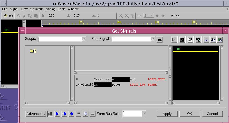
24 Simulation
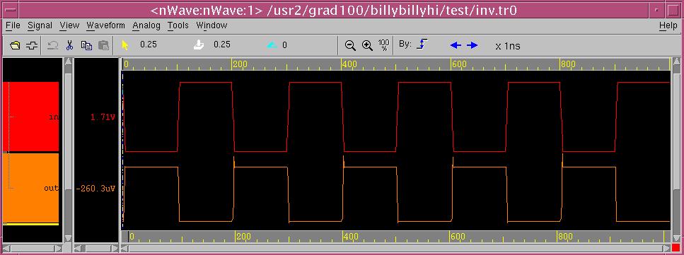
25 Simulation

26 Simulation View the measure results by vi Quit vi command => :q!
SPICE Simulation Program with Integrated Circuit Emphasis
 SPICE Simulation Program with Integrated Circuit Emphasis References: [1] CIC SPICE training manual [3] SPICE manual [2] DIC textbook Sep. 25, 2004 1 SPICE: Introduction Simulation Program with Integrated
HSPICE. Speaker Jh-He Lin
 HSPICE Source : Jh-He Lin Speaker Jh-He Lin Design Flow Declaration Voltage Source Circuit Statements Sub-circuit it Measures Operation Others Advanced Reliable System Lab ARES Lab Chih-Sheng Hou Declaration
Introduction to Full-Custom Circuit Design with HSPICE and Laker
 Introduction to VLSI and SOC Design Introduction to Full-Custom Circuit Design with HSPICE and Laker Course Instructor: Prof. Lan-Da Van T.A.: Tsung-Che Lu Department of Computer Science National Chiao
MOSFET: Mxxx nd ng ns nb modelname W=value L=value Ad As Pd Ps
 ELE447 Lab 1: Introduction to HSPICE In this lab, you will learn how to use HSPICE for simulating the electronic circuits. To be able to simulate a circuit using HSPICE, we need to write a text file that
Lecture 7: SPICE Simulation
 Lecture 7: SPICE Simulation Slides courtesy of Deming Chen Slides based on the initial set from David Harris CMOS VLSI Design Outline Introduction to SPICE DC Analysis Transient Analysis Subcircuits Optimization
The default account setup for the class should allow you to run HSPICE without any further configuration. To verify this, type:
 UNIVERSITY OF CALIFORNIA College of Engineering Department of Electrical Engineering and Computer Sciences HW #1: Circuit Simulation NTU IC541CA (Spring 2004) 1 Objective The objective of this homework
Circuit Simulation Using SPICE ECE222
 Circuit Simulation Using SPICE ECE222 Circuit Design Flow Idea Conception Specification Initial Circuit Design Circuit Simulation Meet Spec? Modify Circuit Design Circuit Implementation 2 Circuit Simulation
INTRODUCTION TO CIRCUIT SIMULATION USING SPICE
 LSI Circuits INTRODUCTION TO CIRCUIT SIMULATION USING SPICE Introduction: SPICE (Simulation Program with Integrated Circuit Emphasis) is a very powerful and probably the most widely used simulator for
EECE 488: Short HSPICE Tutorial. Last updated by: Mohammad Beikahmadi January 2013
 EECE 488: Short HSPICE Tutorial Last updated by: Mohammad Beikahmadi January 2013 SPICE? Simulation Program with Integrated Circuit Emphasis An open source analog circuit simulator Predicts circuit behavior,
Chapter 19. Performing Cell Characterization
 Chapter 19 Most ASIC vendors use Star-Hspice to characterize their standard cell libraries and prepare data sheets by using the basic capabilities of the.measure statement. Input sweep parameters and the
THE SPICE BOOK. Andrei Vladimirescu. John Wiley & Sons, Inc. New York Chichester Brisbane Toronto Singapore
 THE SPICE BOOK Andrei Vladimirescu John Wiley & Sons, Inc. New York Chichester Brisbane Toronto Singapore CONTENTS Introduction SPICE THE THIRD DECADE 1 1.1 THE EARLY DAYS OF SPICE 1 1.2 SPICE IN THE 1970s
Laboratory Lecture 4
 Gheorghe Asachi Technical University of Iasi Faculty of Electronics, Telecommunications and Information Technology Title of Discipline: Computer-Aided Analysis of Electronic Circuits Laboratory Lecture
Mentor Analog Simulators
 ENGR-434 Spice Netlist Syntax Details Introduction Rev 5/25/11 As you may know, circuit simulators come in several types. They can be broadly grouped into those that simulate a circuit in an analog way,
SPICE for Power Electronics and Electric Power
 SPICE for Power Electronics and Electric Power Third Edition Muhammad H. Rashid Life Fellow IEEE /^0\ \Cf*' CRC Press I Taylor & Francis eis Crou Group Boca Raton London New York CRC Press is an imprint
Introduction to SwitcherCAD
 Introduction to SwitcherCAD 1 PREFACE 1.1 What is SwitcherCAD? SwitcherCAD III is a new Spice based program that was developed for modelling board level switching regulator systems. The program consists
SPICE FOR POWER ELECTRONICS AND ELECTRIC POWER
 SPICE FOR POWER ELECTRONICS AND ELECTRIC POWER SECOND EDITION MUHAMMAD H. RASHID University of West Florida Pensacola, Florida, U.S.A. HASAN M. RASHID University of Florida Gainesville, Florida, U.S.A.
WinSpice. The steps to performing a circuit simulation with WinSpice are:
 WinSpice Tutorial 1 A. Introduction WinSpice SPICE is short for Simulation Program with Integrated Circuit Emphasis. SPICE is a general-purpose circuit simulation program for nonlinear dc, nonlinear transient,
PSpice Simulation. The target of computer-aided analysis is to determine the circuit currents and voltages everywhere in the circuit.
 PSpice Simulation The target of computer-aided analysis is to determine the circuit currents and voltages everywhere in the circuit. For PSpice, the circuit is described by a text file called the netlist.
Simulation Using WinSPICE
 Simulation Using WinSPICE David W. Graham Lane Department of Computer Science and Electrical Engineering West Virginia University David W. Graham 2007 Why Simulation? Theoretical calculations only go so
EECE 488: Short HSPICE. Tutorial. Last updated by: Mohammad Beikahmadi January Original presentation by: Jack Shiah
 EECE 488: Short HSPICE Tutorial Last updated by: Mohammad Beikahmadi January 2012 Original presentation by: Jack Shiah SPICE? Simulation Program with Integrated Circuit Emphasis An open source analog circuit
Tsung-Chu Huang. Department of Electronic Engineering National Changhua University of Education /10/4-5 TCH NCUE
 Digital IC Design Tsung-Chu Huang Department of Electronic Engineering National Changhua University of Education Email: tch@cc.ncue.edu.tw 2004/10/4-5 Page 1 Circuit Simulation Tools 1. Switch Level: Verilog,
Figure 1. Main window (Common Interface Window), CIW opens and from the pull down menus you can start your design. Figure 2.
, CIW opens and from the pull down menus you can start your design. Figure 2.") Running Cadence Once the Cadence environment has been setup you can start working with Cadence. You can run cadence from your directory by typing Figure 1. Main window (Common Interface Window), CIW opens
Running Cadence Once the Cadence environment has been setup you can start working with Cadence. You can run cadence from your directory by typing Figure 1. Main window (Common Interface Window), CIW opens
TAMU ECEN 751 Spring Project 1: Matlab Circuit Parser User s Manual
 TAMU ECEN 751 Spring 2014 Project 1: Matlab Circuit Parser User s Manual The purpose of our Matlab parser is to parse in the SPICE like input circuit deck, and store information in Matlab arrays. 1. The
Hands-on Homework 2: Modeling transmission lines
 Hands-on Homework 2: Modeling transmission lines ntroduction n class, we developed a model for a infinite length lossless transmission line (t-line). t was configured as a ladder network of vanishingly
Circuit Simulation with SPICE OPUS
 Circuit Simulation with SPICE OPUS Theory and Practice Tadej Tuma Arpäd Bürmen Birkhäuser Boston Basel Berlin Contents Abbreviations About SPICE OPUS and This Book xiii xv 1 Introduction to Circuit Simulation
Conduction Characteristics of MOS Transistors (for fixed Vds)! Topic 2. Basic MOS theory & SPICE simulation. MOS Transistor
! Topic 2. Basic MOS theory & SPICE simulation. MOS Transistor") Conduction Characteristics of MOS Transistors (for fixed Vds)! Topic 2 Basic MOS theory & SPICE simulation Peter Cheung Department of Electrical & Electronic Engineering Imperial College London (Weste&Harris,
Conduction Characteristics of MOS Transistors (for fixed Vds)! Topic 2 Basic MOS theory & SPICE simulation Peter Cheung Department of Electrical & Electronic Engineering Imperial College London (Weste&Harris,
Topic 2. Basic MOS theory & SPICE simulation
 Topic 2 Basic MOS theory & SPICE simulation Peter Cheung Department of Electrical & Electronic Engineering Imperial College London (Weste&Harris, Ch 2 & 5.1-5.3 Rabaey, Ch 3) URL: www.ee.ic.ac.uk/pcheung/
Conduction Characteristics of MOS Transistors (for fixed Vds) Topic 2. Basic MOS theory & SPICE simulation. MOS Transistor
 Topic 2. Basic MOS theory & SPICE simulation. MOS Transistor") Conduction Characteristics of MOS Transistors (for fixed Vds) Topic 2 Basic MOS theory & SPICE simulation Peter Cheung Department of Electrical & Electronic Engineering Imperial College London (Weste&Harris,
Conduction Characteristics of MOS Transistors (for fixed Vds) Topic 2 Basic MOS theory & SPICE simulation Peter Cheung Department of Electrical & Electronic Engineering Imperial College London (Weste&Harris,
Experiment 2 Introduction to PSpice
 Experiment 2 Introduction to PSpice W.T. Yeung and R.T. Howe UC Berkeley EE 105 Fall 2004 1.0 Objective One of the CAD tools you will be using as a circuit designer is SPICE, a Berkeleydeveloped industry-standard
NGSPICE- Usage and Examples
 NGSPICE- Usage and Examples Debapratim Ghosh deba21pratim@gmail.com Electronic Systems Group Department of Electrical Engineering Indian Institute of Technology Bombay February 2013 Debapratim Ghosh Dept.
EEC 216 W08 Problem Set #1 Solutions
 EEC 216 W08 Problem Set #1 Solutions Rajeevan Amirtharajah Dept. of Electrical and Computer Engineering University of California, Davis February 11, 2008 Problem 1 1.1 Figure 1 shows the layout for a minimum-sized
Yuan-Piao Lee Te-Hsiu Chen Chienkuo Technology University, ChungHua, Taiwan, ROC
 Select the MODEL set HSPICE simulation results Yuan-Piao Lee Te-Hsiu Chen Chienkuo Technology University, ChungHua, Taiwan, ROC ABSTRACT To the the HSPICE design of circuit is quite convenient, this paper
Modeling MOS Transistors. Prof. MacDonald
 Modeling MOS Transistors Prof. MacDonald 1 Modeling MOSFETs for simulation l Software is used simulate circuits for validation l Original program SPICE UC Berkeley Simulation Program with Integrated Circuit
A Short SPICE Tutorial
 A Short SPICE Tutorial Kenneth H. Carpenter Department of Electrical and Computer Engineering Kanas State University September 15, 2003 - November 10, 2004 1 Introduction SPICE is an acronym for Simulation
A brief introduction on HSPICE. Siavash Kananian Sharif University of Technology Electronics III
 A brief introduction on HSPICE Siavash Kananian Sharif University of Technology Electronics III Electronics III - Fall 2011 What is Spice? Simulation Program with Integrated Circuit Emphasis General purpose
Lab 3: Circuit Simulation with PSPICE
 Page 1 of 11 Laboratory Goals Introduce text-based PSPICE as a design tool Create transistor circuits using PSPICE Simulate output response for the designed circuits Introduce the Curve Tracer functionality.
Elad Alon HW #1: Circuit Simulation EECS 141 Due Thursday, Aug. 30th, 5pm, box in 240 Cory
 UNIVERSITY OF CALIFORNIA College of Engineering Department of Electrical Engineering and Computer Sciences Last modified on August 20, 2012 by Elad Alon Elad Alon HW #1: Circuit Simulation EECS 141 Due
TTL LOGIC and RING OSCILLATOR TTL
 ECE 2274 TTL LOGIC and RING OSCILLATOR TTL We will examine two digital logic inverters. The first will have a passive resistor pull-up output stage. The second will have an active transistor and current
Lecture 3: Sizing & Simulation
 High Speed CMOS VLSI Design Lecture 3: Sizing & Simulation (c) 1997 David Harris 1.0 Sizing with Side loads We have learned to size simple paths consisting of a cascade of gates in which each gate drives
Experiment #1 Introduction to SPICE
 Jonathan Roderick Experiment #1 Introduction to SPICE Introduction: This experiment is designed to familiarize the student with SPICE. SPICE simulations will be needed for prelabs and projects contained
Simulation Program with Integrated Circuits Emphasis = SPICE
 What is in the name? Computer Club short course on SPICE, April 2002 SPICE Short Course By Dr. Muhammad Elrabaa Simulation Program with Integrated Circuits Emphasis = SPICE What does it do? SPICE is used
Mor M. Peretz Power Electronics Laboratory Department of Electrical and Computer Engineering Ben-Gurion University of the Negev, ISRAEL
 Mor M. Peretz Power Electronics Laboratory Department of Electrical and Computer Engineering Ben-Gurion University of the Negev, ISRAEL [1] Models and Devices A model defines the electrical behavior of
Techcode. High Efficiency 1MHz, 2A Step Up Regulator TD8208. General Description. Features. Applications. Package Types DATASHEET
 General Description Features TD8208 is a high efficiency, current mode control Boost DC to DC regulator with an integrated 120mΩ RDS(ON) N channel MOSFET. The fixed 1MHz switching frequency and internal
A Brief Handout for Introduction to
 A Brief Handout for Introduction to Electric cal Engineering Course This handout is a compilation of PSPICE, A Brief Primer, Department of Electrical and Systems Engineering, University of Pennsylvania
Introduction to LTSpice
 Usage of Introduction to Department of EECS Jacobs University Bremen Instructors - Dr. Mathias Bode and - e-mail - m.bode@jacobs-university.de tel.: +49 421 200-3139 - u.pagel@jacobs-university.de tel.:
1.3 An Introduction to WinSPICE
 Chapter 1 Introduction to CMOS Design 23 After the GDS file is generated, we can use the Gds2Tlc program to convert the GDS file back into TLC files. In the setups we must specify a directory where the
AMPLIFIERS MACRO-MODELING
 AMPLIFIERS MACRO-MODELING Version 1 - May 1995 TABLE Introduction Circuit principle Unity gain Gain for small amplitude signals Models and simulations Ideal model with a voltage source Amplifier model
LTSpice Basic Tutorial
 Index: I. Opening LTSpice II. Drawing the circuit A. Making Sure You Have a GND B. Getting the Parts C. Placing the Parts D. Connecting the Circuit E. Changing the Name of the Part F. Changing the Value
Gunning Transceiver Logic Interface Bus Design Project
 Gunning Transceiver Logic Interface Bus Design Project Group #14 EE 307 Winter 2007 February 23, 2007 Robert Hursig rhursig@calpoly.edu Tommy Oleksyn toleksyn@calpoly.edu http://www.drdphd.com/02_14.pdf
FP kHz 7A High Efficiency Synchronous PWM Boost Converter
 500kHz 7A High Efficiency Synchronous PWM Boost Converter General Description The FP6277 is a current mode boost DC-DC converter with PWM/PSM control. Its PWM circuitry with built-in 30mΩ high side switch
Intelligent Systems Group Department of Electronics. An Evolvable, Field-Programmable Full Custom Analogue Transistor Array (FPTA)
") Department of Electronics n Evolvable, Field-Programmable Full Custom nalogue Transistor rray (FPT) Outline What`s Behind nalog? Evolution Substrate custom made configurable transistor array (FPT) Ways
Department of Electronics n Evolvable, Field-Programmable Full Custom nalogue Transistor rray (FPT) Outline What`s Behind nalog? Evolution Substrate custom made configurable transistor array (FPT) Ways
DIGITAL CIRCUIT SIMULATION USING HSPICE
 February 7, 2001 DIGITAL CIRCUIT SIMULATION USING HSPICE Charles R. Kime Dept. of Electrical and Computer Engineering University of Wisconsin Madison The pdf version of this document has extensive hyperlinks
Experiment #1 Introduction to SPICE
 Jonathan Roderick Onder Oz and Tyler Rather Experiment #1 Introduction to SPICE Introduction: This experiment is designed to familiarize the student with SPICE. SPICE simulations will be needed for prelabs
Final for EE 421 Digital Electronics and ECG 621 Digital Integrated Circuit Design Fall, University of Nevada, Las Vegas
 Final for EE 421 Digital Electronics and ECG 621 Digital Integrated Circuit Design Fall, University of Nevada, Las Vegas NAME: Show your work to get credit. Open book and closed notes. Unless otherwise
SPICE 4: Diodes. Chris Winstead. ECE Spring, Chris Winstead SPICE 4: Diodes ECE Spring, / 28
 SPICE 4: Diodes Chris Winstead ECE 3410. Spring, 2015. Chris Winstead SPICE 4: Diodes ECE 3410. Spring, 2015. 1 / 28 Preparing for the Exercises In this session, we will simulate several diode configurations
Integrated, Low Voltage, Dynamically Adaptive Buck-Boost Boost Converter A Top-Down Design Approach
 Integrated, Low Voltage, Dynamically Adaptive Buck-Boost Boost Converter A Top-Down Design Approach Georgia Tech Analog Consortium Biranchinath Sahu Advisor: Prof. Gabriel A. Rincón-Mora Analog Integrated
Faculty of Engineering 4 th Year, Fall 2010
 4. Inverter Schematic a) After you open the previously created Inverter schematic, an empty window appears where you should place your components. To place an NMOS, select Add- >Instance or use shortcut
ESD-Transient Detection Circuit with Equivalent Capacitance-Coupling Detection Mechanism and High Efficiency of Layout Area in a 65nm CMOS Technology
 ESD-Transient Detection Circuit with Equivalent Capacitance-Coupling Detection Mechanism and High Efficiency of Layout Area in a 65nm CMOS Technology Chih-Ting Yeh (1, 2) and Ming-Dou Ker (1, 3) (1) Department
QUICK START GUIDE FOR DEMONSTRATION CIRCUIT 781 HIGH EFFICIENCY SYNCHRONOUS NONISOLATED FLYBACK
 DESCRIPTION QUICK START GUIDE FOR DEMONSTRATION CIRCUIT 781 LTC3803ES6 Demonstration circuit 781 is a Telecom DC/DC converter featuring the LTC3803ES6 constant frequency current mode flyback controller.
Using TDK SPICE Netlist Library and Its Basic Applications
 Using TDK SPICE Netlist Library and Its Basic Applications Katsufumi EHATA Application Center, TDK Corporation Feb. 14, 2007. AN-NL06B001Rev1_en Abstract Given that circuit design by simulators has recently
HSPICE (from Avant!) offers a more robust, commercial version of SPICE. PSPICE is a popular version of SPICE, available from Orcad (now Cadence).
 offers a more robust, commercial version of SPICE. PSPICE is a popular version of SPICE, available from Orcad (now Cadence).") Electronics II: SPICE Lab ECE 09.403/503 Team Size: 2-3 Electronics II Lab Date: 3/9/2017 Lab Created by: Chris Frederickson, Adam Fifth, and Russell Trafford Introduction SPICE (Simulation Program for
Electronics II: SPICE Lab ECE 09.403/503 Team Size: 2-3 Electronics II Lab Date: 3/9/2017 Lab Created by: Chris Frederickson, Adam Fifth, and Russell Trafford Introduction SPICE (Simulation Program for
PREFACE 5 THE AUTHOR 6 INDEX 7 FOREWORD 21 1 LTSPICEIV: INTRODUCTION AND HISTORY 25
 INDEX PREFACE 5 THE AUTHOR 6 INDEX 7 FOREWORD 21 1 LTSPICEIV: INTRODUCTION AND HISTORY 25 1.1 Circuit simulation with LTspice IV 25 1.1.1 The three basic steps 25 1.1.2 Results analysis 27 1.2 The story
Power Conditioning Electronics Dr. Lynn Fuller Webpage:
 ROCHESTER INSTITUTE OF TECHNOLOGY MICROELECTRONIC ENGINEERING Power Conditioning Electronics Dr. Lynn Fuller Webpage: http://people.rit.edu/lffeee 82 Lomb Memorial Drive Rochester, NY 14623-5604 Email:
MOS IC Amplifiers. Token Ring LAN JSSC 12/89
 MO IC Amplifiers MOFETs are inferior to BJTs for analog design in terms of quality per silicon area But MO is the technology of choice for digital applications Therefore, most analog portions of mixed-signal
EE 140 HW7 SOLUTION 1. OPA334. a. From the data sheet, we see that. Vss 0.1V Vcm Vdd 1.5V
 EE 140 HW7 SOLUTION 1. OPA334 a. From the data sheet, we see that Vss 0.1V Vcm Vdd 1.5V The input common mode voltage must remain at least 1.5V below vdd. The input common mode voltage can be below Vss.
High-Speed Serial Interface Circuits and Systems
 High-Speed Serial Interface Circuits and Systems Design Exercise4 Charge Pump Charge Pump PLL ɸ ref up PFD CP LF VCO down ɸ out ɸ div Divider Converts PFD phase error pulse (digital) to charge (analog).
EE 330 Laboratory 8 Discrete Semiconductor Amplifiers
 EE 330 Laboratory 8 Discrete Semiconductor Amplifiers Fall 2018 Contents Objective:...2 Discussion:...2 Components Needed:...2 Part 1 Voltage Controlled Amplifier...2 Part 2 A Nonlinear Application...3
CMOS synchronous Buck switching power supply Raheel Sadiq November 28, 2016
 CMOS synchronous Buck switching power supply Raheel Sadiq November 28, 2016 Part 1: This part of the project is to lay out a bandgap. We previously built our bandgap in HW #13 which supplied a constant
EE 320 L LABORATORY 9: MOSFET TRANSISTOR CHARACTERIZATIONS. by Ming Zhu UNIVERSITY OF NEVADA, LAS VEGAS 1. OBJECTIVE 2. COMPONENTS & EQUIPMENT
 EE 320 L ELECTRONICS I LABORATORY 9: MOSFET TRANSISTOR CHARACTERIZATIONS by Ming Zhu DEPARTMENT OF ELECTRICAL AND COMPUTER ENGINEERING UNIVERSITY OF NEVADA, LAS VEGAS 1. OBJECTIVE Get familiar with MOSFETs,
FP6276B 500kHz 6A High Efficiency Synchronous PWM Boost Converter
 500kHz 6A High Efficiency Synchronous PWM Boost Converter General Description The is a current mode boost DC-DC converter with PWM/PSM control. Its PWM circuitry with built-in 40mΩ high side switch and
Introduction to PSpice
 Electric Circuit I Lab Manual 4 Session # 5 Introduction to PSpice 1 PART A INTRODUCTION TO PSPICE Objective: The objective of this experiment is to be familiar with Pspice (learn how to connect circuits,
The University of Evansville SwitcherCAD III Component Library
 The University of Evansville SwitcherCAD III Component Library University of Evansville June 17, 2008 SwitcherCADIII (SwCAD III) is a high-performance, general-purpose circuit simulation program. It was
EE 230 Lab Lab 9. Prior to Lab
 MOS transistor characteristics This week we look at some MOS transistor characteristics and circuits. Most of the measurements will be done with our usual lab equipment, but we will also use the parameter
EECS 312: Digital Integrated Circuits Lab Project 1 Introduction to Schematic Capture and Analog Circuit Simulation
 EECS 312: Digital Integrated Circuits Lab Project 1 Introduction to Schematic Capture and Analog Circuit Simulation Teacher: Robert Dick GSI: Shengshuo Lu Assigned: 5 September 2013 Due: 17 September 2013
Lecture 4. The CMOS Inverter. DC Transfer Curve: Load line. DC Operation: Voltage Transfer Characteristic. Noise in Digital Integrated Circuits
 Noise in Digital Integrated Circuits Lecture 4 The CMOS Inverter i(t) v(t) V DD Peter Cheung Department of Electrical & Electronic Engineering Imperial College London URL: www.ee.ic.ac.uk/pcheung/ E-mail:
Chapter 8. Chapter 9. Chapter 6. Chapter 10. Chapter 11. Chapter 7
 5.5 Series and Parallel Combinations of 246 Complex Impedances 5.6 Steady-State AC Node-Voltage 247 Analysis 5.7 AC Power Calculations 256 5.8 Using Power Triangles 258 5.9 Power-Factor Correction 261
Engineering 3821 Fall Pspice TUTORIAL 1. Prepared by: J. Tobin (Class of 2005) B. Jeyasurya E. Gill
 B. Jeyasurya E. Gill") Engineering 3821 Fall 2003 Pspice TUTORIAL 1 Prepared by: J. Tobin (Class of 2005) B. Jeyasurya E. Gill 2 INTRODUCTION The PSpice program is a member of the SPICE (Simulation Program with Integrated Circuit
Engineering 3821 Fall 2003 Pspice TUTORIAL 1 Prepared by: J. Tobin (Class of 2005) B. Jeyasurya E. Gill 2 INTRODUCTION The PSpice program is a member of the SPICE (Simulation Program with Integrated Circuit
Techcode TD8215. Step-up DC/DC Controller. General Description. Features. Applications. Pin Configurations DATASHEET TD8215 INV SCP VDD CTL
 General Description Features The is a single PWM, step up DC DC controller with low operating voltage application integrating softstart and short circuit detection function. The oscillator switching frequency
CHAPTER 6 DIGITAL CIRCUIT DESIGN USING SINGLE ELECTRON TRANSISTOR LOGIC
 94 CHAPTER 6 DIGITAL CIRCUIT DESIGN USING SINGLE ELECTRON TRANSISTOR LOGIC 6.1 INTRODUCTION The semiconductor digital circuits began with the Resistor Diode Logic (RDL) which was smaller in size, faster
Lab 7 PSpice: Time Domain Analysis
 Lab 7 PSpice: Time Domain Analysis OBJECTIVES 1. Use PSpice Circuit Simulator to simulate circuits containing capacitors and inductors in the time domain. 2. Practice using a switch, and a Pulse & Sinusoidal
A radiation-hardened optical receiver chip
 This article has been accepted and published on J-STAGE in advance of copyediting. Content is final as presented. A radiation-hardened optical receiver chip Xiao Zhou, Ping Luo a), Linyan He, Rongxun Ling
EE 330 Laboratory 8 Discrete Semiconductor Amplifiers
 EE 330 Laboratory 8 Discrete Semiconductor Amplifiers Fall 2017 Contents Objective:... 2 Discussion:... 2 Components Needed:... 2 Part 1 Voltage Controlled Amplifier... 2 Part 2 Common Source Amplifier...
PSPICE A brief primer
 PSPICE A brief primer Contents 1. Introduction 2. Use of PSpice with OrCAD Capture 2.1 Step 1: Creating the circuit in Capture 2.2 Step 2: Specifying the type of analysis and simulation BIAS or DC analysis
Introduction to LTSPICE Dr. Lynn Fuller Electrical and Microelectronic Engineering
 ROCHESTER INSTITUTE OF TECHNOLOGY MICROELECTRONIC ENGINEERING Introduction to LTSPICE Dr. Lynn Fuller Electrical and 82 Lomb Memorial Drive Rochester, NY 14623-5604 Tel (585) 475-2035 Fax (585) 475-5041
Electronic Circuit Casebook. Dr. Lynn Fuller
 ROCHESTER INSTITUTE OF TECHNOLOGY MICROELECTRONIC ENGINEERING Electronic Circuit Casebook Dr. Lynn Fuller Webpage: http://people.rit.edu/lffeee 82 Lomb Memorial Drive Rochester, NY 146235604 Tel (585)
SIMetrix/ Advanced Power System Simulation. SIMPLIS Reference Manual
 SIMetrix/ Advanced Power System Simulation SIMPLIS Reference Manual Copyright 1992-2004 Catena Software Ltd. Contact Catena Software Ltd., Terence House, 24 London Road, Thatcham, RG18 4LQ, United Kingdom
Introduction to Matlab, HSPICE and SUE
 ES 154 Laboratory Assignment #2 Introduction to Matlab, HSPICE and SUE Introduction The primary objective of this lab is to familiarize you with three tools that come in handy in circuit design and analysis.
UNIVERSITY OF CALIFORNIA College of Engineering Department of Electrical Engineering and Computer Sciences
 UNIVERSITY OF CALIFORNIA College of Engineering Department of Electrical Engineering and Computer Sciences Jan M. Rabaey Homework #1: Circuit Simulation EECS 141 Due Friday, January 29, 5pm, box in 240
Set-up of Assura RCX-HF tools for the AMS S35 process. Configuration files and usage guide. 1
 Internal Research Report: Set-up of Assura RCX-HF tools for the AMS S35 process. Configuration files and usage guide. 1 Revision history: Rev 1.0 October 31 st 2008 Xavier Aragones, created. Index I. Files
Practice Homework Problems for Module 1
 Practice Homework Problems for Module 1 1. Unsigned base conversions (LO 1-1). (a) (2C9E) 16 to base 2 (b) (1101001) 2 to base 10 (c) (1101001) 2 to base 16 (d) (8576) 10 to base 16 (e) (A27F) 16 to base
M A S S A C H U S E T T S I N S T I T U T E O F T E C H N O L O G Y DEPARTMENT OF ELECTRICAL ENGINEERING AND COMPUTER SCIENCE
 M A S S A C H U S E T T S I N S T I T U T E O F T E C H N O L O G Y DEPARTMENT OF ELECTRICAL ENGINEERING AND COMPUTER SCIENCE General Information 6.004 Computation Structures Lab #1 Lab assignments are
A Study of PN Junction Diffusion Capacitance of MOSFET in Presence of Single Event Transient
 Journal of Electronic Testing (217) 33:769 773 https://doi.org/1.17/s1836-17-5694-5 A Study of PN Junction Diffusion Capacitance of MOSFET in Presence of Single Event Transient Tengyue Yi 1 & Yi Liu 1
Fall Modeling Skin Effect. Featuring: Noise Source Macro. Modeling Skin Effect. Common Digital Mistakes MC5 File Hierarchy
 Applications for Micro-Cap Users Fall 1997 Modeling Skin Effect Featuring: Noise Source Macro Modeling Skin Effect Common Digital Mistakes MC5 File Hierarchy News In Preview This issue features an article
Differential Amplifier Design
 Fall - 2009 EE114 - Design Project Differential Amplifier Design Submitted by Piyush Keshri (0559 4497) Jeffrey Tu (0554 4565) On November 20th, 2009 EE114 - Design Project Stanford University Page No.
RT9266B. Tiny Package, High Efficiency, Step-Up DC/DC Converter. General Description. Features. Applications. Ordering Information RT9266B
 Tiny Package, High Efficiency, Step-Up DC/DC Converter General Description The RT9266B is a compact, high efficiency, and low voltage step-up DC/DC converter with an Adaptive Current Mode PWM control loop,
MP A,1MHz, Synchronous, Step-up Converter with Output Disconnect
 The Future of Analog IC Technology MP3414 1.8A,1MHz, Synchronous, Step-up Converter with Output Disconnect DESCRIPTION The MP3414 is a high-efficiency, synchronous, current mode, step-up converter with
DESIGN AND ANALYSIS OF LOW POWER CHARGE PUMP CIRCUIT FOR PHASE-LOCKED LOOP
 DESIGN AND ANALYSIS OF LOW POWER CHARGE PUMP CIRCUIT FOR PHASE-LOCKED LOOP 1 B. Praveen Kumar, 2 G.Rajarajeshwari, 3 J.Anu Infancia 1, 2, 3 PG students / ECE, SNS College of Technology, Coimbatore, (India)
4.4 Applications of Transient Analysis
 4.4. Applications of Transient Analysis 207 orders of magnitude smaller than the largest signal present in the circuit of the same kind. 9. If, by a process of elimination, you identify a nonlinear capacitance
FP V, 3.1A, 550KHz High Efficiency Low Ripple Synchronous Step-Up Converter. Description. Features. Applications.
 5V, 3.1A, 550KHz High Efficiency Low Ripple Synchronous Step-Up Converter Description The is a high efficiency, fixed frequency 550KHz, current mode PWM boost DC/DC converter which could operate battery
Digital Integrated Circuits
 Digital Integrated Circuits YuZhuo Fu contact:fuyuzhuo@ic.sjtu.edu.cn Office location:417 room WeiDianZi building,no 800 DongChuan road,minhang Campus Introduction 3.CMOS Inverter Introduction outline