Acquisition. Some slides from: Yung-Yu Chuang (DigiVfx) Jan Neumann, Pat Hanrahan, Alexei Efros
|
|
|
- Bertram Curtis
- 5 years ago
- Views:
Transcription


1 Acquisition Some slides from: Yung-Yu Chuang (DigiVfx) Jan Neumann, Pat Hanrahan, Alexei Efros

2 Image Acquisition Digital Camera Film
3 Outline Pinhole camera Lens Lens aberrations Exposure Sensors Noise Sensing color
4 Camera trial #1 scene film Put a piece of film in front of an object. source: Yung-Yu Chuang
5 Pinhole camera pinhole camera scene barrier film Add a barrier to block off most of the rays It reduces blurring The pinhole is known as the aperture The image is inverted
6
7 Modeling projection The coordinate system Put the optical center (Center Of Projection) at the origin Put the image plane (Projection Plane) in front of the COP The camera looks down the negative z axis we need this if we want right-handed-coordinates
8 Modeling projection Projection equations Compute intersection with PP of ray from (x,y,z) to COP Derived using similar triangles (on board) We get the projection by throwing out the last coordinate:
9 In Homogenous Coordinates Projection is a matrix multiply using homogeneous coordinates:

10 Projection

11 Projection
12 Pinhole camera pinhole camera scene barrier film Add a barrier to block off most of the rays It reduces blurring The pinhole is known as the aperture The image is inverted
13 Shrinking the Pinhole Aperture Why make the aperture as small as possible? Less light gets through Diffraction effect
14 Shrinking the Pinhole Aperture Sharpest image is obtained when: pinhole diameter d = 2 f λ Example: If f = 50mm, λ = 600nm (red), d = 0.36mm
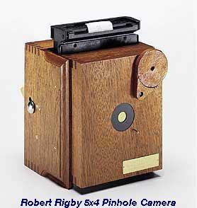
15 High-end commercial pinhole cameras ~$200


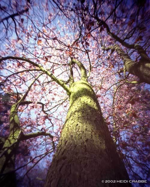
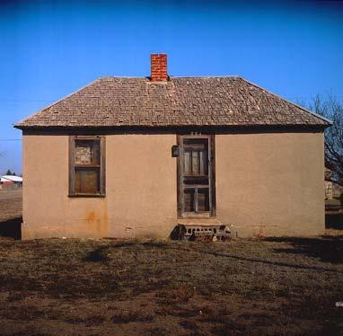
16 Pinhole Images Exposure 4 seconds Exposure 96 minutes Images copyright 2000 Zero Image Co.
17 Outline Pinholecamera Lens Lens Aberrations Exposure Sensors Noise Sensing color
18 Adding a lens scene film
19 Adding a lens circle of confusion scene lens film A lens focuses light onto the film There is a specific distance at which objects are in focus Other points project to a circle of confusion in the image
20 (Thin) Lens Thin lens equation: Any object point satisfying this equation is in focus
21 Circle of Confusion aperture Blur Circle, b aperture diameter d o i o' i' Blur Circle Diameter b : Derive using similar triangles b = d i' ( i ' i)


22 Aperture controls Depth of Field f / 5.6 Changing the aperture affects depth of field Smaller aperture: better DOF increased exposure f / 32

23 Depth of Field

24 Thick Lens Corrects aberrations Change zoom

25 Field of View (Zoom)

26 Field of View (Zoom)
27 FOV depends on Focal Length ϕ/2 d/2 f f d = image size 2
28 FOV depends on Focal Length d = image size 2
29 FOV depends on Focal Length d = image size 2 Smaller FOV larger Focal Length
30 FOV depends on Focal Length focal point image size For closer objects: if focal point is larger but image distance and size remain unchanged the objects in focus are more distant.

31 Simplified Zoom Lens in Operation From wikipedia
32 Outline Pinholecamera Lens Lens aberrations Exposure Sensors Noise Sensing color
33 Radial Distortion No distortion Pin cushion Barrel Radial distortion of the image Caused by imperfect lenses Deviations are most noticeable for rays that pass through the edge of the lens


34 Correcting radial distortion from Helmut Dersch


35 Radial Distortions No Distortion Barrel Distortion Pincushion Distortion Radial distance from Image Center: r u = r d + k 1 r d 3 r u = undistorted radius r d = distorted radius


36 Correcting Radial Distortions Before After

37 Vignetting photo by Robert Johnes
38 Vignetting L3 L2 L1 B A More light passes through lens L3 for scene point A than scene point B Results in spatially non-uniform brightness (in the periphery of the image)
39 Chromatic Aberration longitudinal chromatic aberration (axial) transverse chromatic aberration (lateral)
 Cosina 3.5-4.5/19-35 @ 20 mm Good lens Carl Zeiss Distagon 2.")
40 Chromatic Aberration longitudinal chromatic aberration (axial) Canon EF 85/1.2 L USM transverse chromatic aberration (lateral) Cosina 20 mm Good lens Carl Zeiss Distagon 2.8/21


41 Chromatic Aberration Near Lens Center Near Lens Outer Edge

42 Spherical aberration Rays parallel to the axis do not converge Outer portions of the lens yield smaller focal lengths
43 Spherical aberration Spherical lens are free of chromatic aberration but do not focus well. Parabolic lens does.
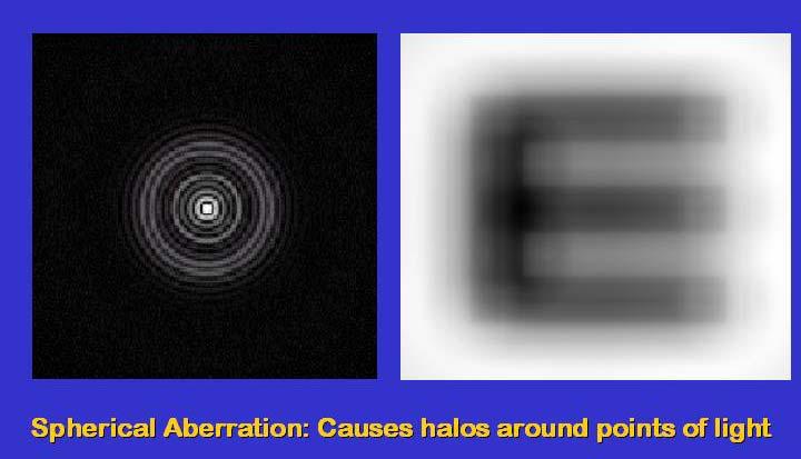
44 Spherical aberration


45 Astigmatism Different focal length for inclined rays

46 Astigmatism Change in size and shape of blur patches


47 Coma point off the axis depicted as comet shaped blob

48 Lens Glare Stray inter-reflections of light within the optical lens system Happens when very bright sources are present in the scene Reading:
49 Outline Pinholecamera Lens Lens aberrations Exposure Sensors Noise Sensing color


50 Exposure Two main parameters: Aperture (in f stop) Shutter speed (in fraction of a second)
51 Shutter

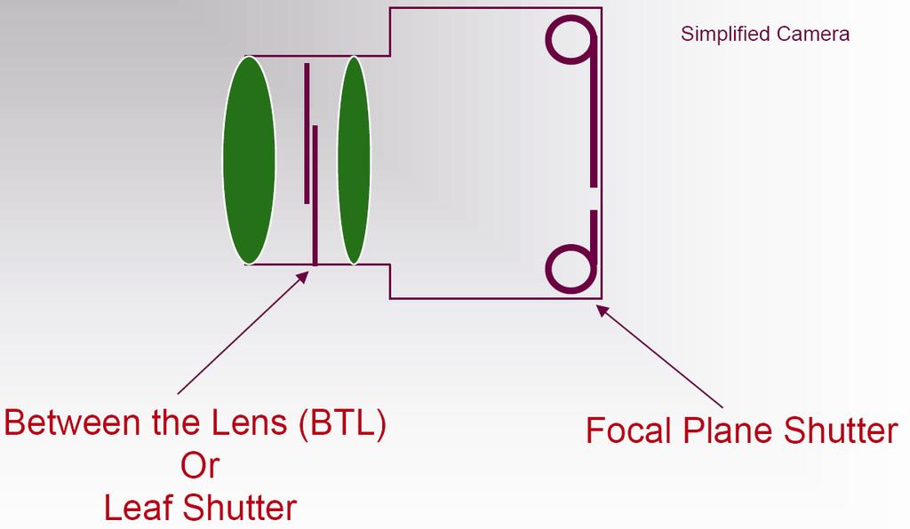
52 Leaf Shutter Advantages Uniform illumination Entire frame illuminated at once Disadvantages Illumination not constant over time Limitations on shutter speed
 Disadvantages May cause time")
53 Focal Plane Shutter Advantages Cost effective (one shutter needed for all lenses Can achieve very fast shutter speeds (~1/10000 sec) Disadvantages May cause time distortion

54 Aperture Aperture is the diameter of the lens opening, usually specified by f-stop, f/d, a fraction of the focal length. f/2.0 on a 50mm means that the aperture is 25mm f/2.0 on a 100mm means that the aperture is 50mm When a change in f-stop occurs, the light is either doubled or cut in half. Lower f-stop, more light (larger lens opening) Higher f-stop, less light (smaller lens opening)

55 Aperture Constant speed.
56 Shutter speed Rule of Thumb 1 step in the shutter speed scale corresponds to 1 stop in the aperture scale. Handheld camera: shutter speed = 1 / f Stabilized gear: 2-3 shutter speeds slower Typical speeds: 1/1000 s, 1/500 s, 1/250 s, 1/125 s, 1/60 s, 1/30 s, 1/15 s, 1/8 s, 1/4 s, 1/2 s 1 s

57 Aperture vs. Shutter Depth of Field f/22 f/4 Small Aperture Large Aperture (Low speed) (High speed)

")
58 Aperture vs. Shutter Motion Blur 1/30 f/22 1/6400 f/2.5 Small Aperture (Low speed) Large Aperture (High speed)

59 Dynamic Range
60 Short exposure Real world radiance Picture intensity dynamic range Pixel value 0 to 255


61 Long exposure Real world radiance Picture intensity dynamic range Pixel value 0 to 255

62 Varying shutter speeds

63 HDR High Dynamic Range
64 Outline Pinholecamera Lens Lens aberrations Exposure Sensors Noise Sensing color

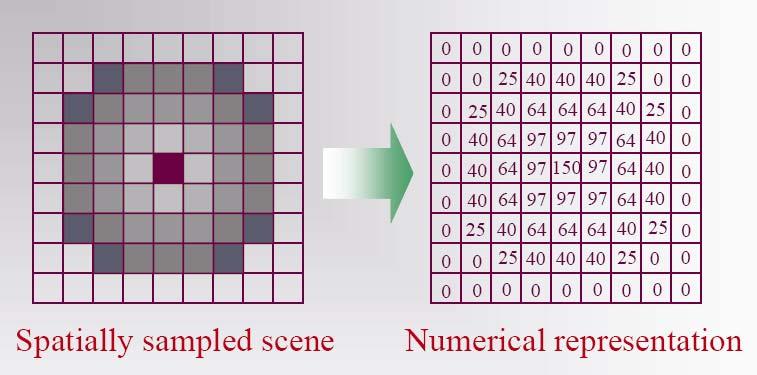
65 Spatial Sampling When a continuous scene is imaged on the sensor, the continuous image is divided into discrete elements - picture elements (pixels)

66 Spatial Sampling
67 Sampling The density of the sampling denotes the separation capability of the resulting image Image resolution defines the finest details that are still visible by the image We use a cyclic pattern to test the separation capability of an image 0 x
68 Sampling Frequency
69 Sampling Frequency
70 Nyquist Frequency Nyquist Rule: To observe details at frequency f (wavelength d) one must sample at frequency > 2f (sampling intervals < d/2) The Frequency 2f is the NYQUIST frequency. Aliasing: If the pattern wavelength is less than 2d erroneous patterns may be produced. 1D Example: 0

71 Aliasing - Moiré Patterns
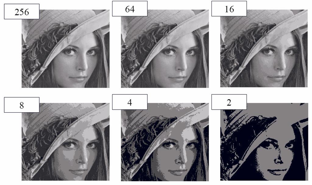
72 Quantization
73 Digitizers (Quantization)
74 Image Sensors CCD Charge Coupled Device CMOS Complementary Metal Oxide Semiconductor

75 MOS (Metal Oxide Semiconductor) Photosensitive element Charge acquired depends on the number of photons which reach the element CCD devices are arrays of this basic element
76 Photoelectric Effect photon photon Increasing energy Conduction Band Valence Band 1.26eV Hole Electron Thermally generated electrons are indistinguishable from photo-generated electrons Dark Current.
 60% (CCD)")
77 Quantum Efficiency Not every photon hitting a pixel creates a free electron Quantum Efficiency (QE) = electrons collected / photons hitting the pixel QE heavily depends on the wavelength QE [%] blue green red QE < 100% degrades the SNR of a camera lambda [nm] SNR e = QE SNR p Typical max QE values : 25% (CMOS) 60% (CCD)

78 CCD (Charge Coupled Device) Boyle and Smith, 1969, Bell Labs Converts light into electrical signal (pixels)


79 CCD Readout Bucket Brigade Integration Charge Shift and Read-out Charge Amplifier
 The chip outputs digital bits Much faster than CCD")
80 CMOS (Complementary Metal-Oxide Semiconductor) Each pixel owns its own charge-voltage conversion No need for external shutter (electronic shutter) The chip outputs digital bits Much faster than CCD devices

81 CCD vs. CMOS Mature technology Specific technology High production cost High power consumption Higher fill factor Blooming Sequential readout Recent technology Standard IC technology Cheap Low power Less sensitive Per pixel amplification Random pixel access Smart pixels On chip integration with other components
82 Sensor Parameters Fill factor The area in the sensor that is truly sensitive to light Shift registers and others can reduce it up to a 30% Well capacity The quantity of charge that can be stored in each pixel Close relation with pixel dimensions Integration time: Exposure time that is required to excite the CCD elements Depends on the scene brightness Acquisition time: Time needed to transfer the information gathered by the CCD Depends on the number of pixels in the sensor

83 Fill Factor The ratio between the light sensitive pixel area and the total pixel area. Total pixel area: 5µm x 5µm Photo Sensing Area Fill factor 40%
84 Outline Pinholecamera Lens Lens aberrations Exposure Sensors Noise Sensing color
85 Sensor noise Noise Sources Photon noise / Shot Noise (Poisson) Dark Noise (Constant) Thermal noise (Poisson) Resetting (fixed) Read-out noise Blooming (After T. Lomheim, The Aerospace Corporation)
86 Photon Shot Noise Light is quantum in nature Noise due to statistics of the detected photons themselves The probability distribution for N photons to be counted in an observation time T is Poisson P ( N F, T ) = ( FT ) N FT e N! F = fixed average flux (photons/sec)
87 Poisson Distribution, FT = N Poisson Distribution : std equals sqrt of Mean. σ = FT = 2 shot N photons
88 Poisson Distribution, FT = N
89 Poisson Distribution, FT = N
90 Poisson Distribution, FT = As FT grows, Poisson distribution approaches Gaussian distribution. Signal To Noise (SNR) Increases with Mean. SNR = N σ 2 2 N = N N 2 = N


91 Photon Noise More noise in bright parts of the image You can identify the white and black regions from the noise image


92 Photon Noise Photon Noise more noticeable in dark images.
93 Dark Current Noise Electron emission when no light Dark current noise is high for long exposures To remove (some) of it Calibrate the camera (make response linear) Capture the image of the scene as usual Cover the lens with the lens cap and take another picture Subtract the second image from the first image


94 Dark Current Noise Original image + Dark Current Noise Image with lens cap on Result of subtraction Copyright Timo Autiokari,
 Photon Noise (QE")
95 Sensor noise ideal relationship between electrons and impinging photons CCD capacity limit Light Signal (QE = 50) Photon Noise (QE = 50)
96 Outline Pinholecamera Lens Lens aberrations Exposure Sensors Noise Sensing color


97 Sensing Color light beam splitter 3 CCD Bayer pattern Foveon X3 TM
98 Multi-Chip wavelength dependent
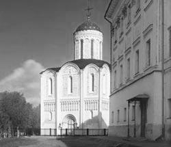
99 Field Sequential
100 Field Sequential
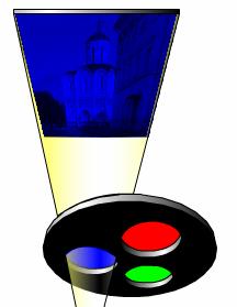
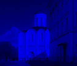
101 Field Sequential
 Fuji")
102 Color Filter Array (CFA) Fuji Corporation
103 Color filter array Bayer pattern Color filter arrays (CFAs)/color filter mosaics


104 Bayer s pattern
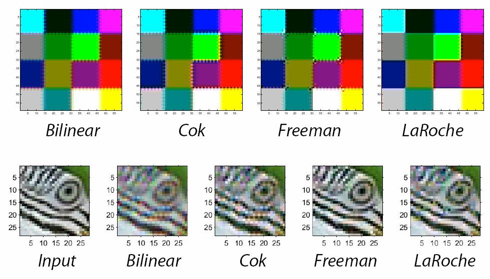
105 Demosaicking CFA s


106 Color filter array red green blue output


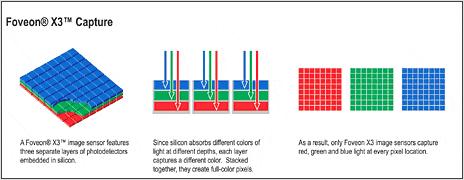
107 X3 technology red green blue output


108 Foveon X3 sensor Bayer CFA X3 sensor


109 Cameras with X3 Sigma SD14 Polaroid X530 Hanvision HVDUO 5M/10M Out of production
110 Color processing After color values are recorded, more color processing usually happens: White balance Non-linearity to approximate film response or match TV monitor gamma


111 White Balance warmer +3 automatic white balance
112 Gamma Correction Gamma correction applied by the converter redistributes the pixel luminance values so that limited brightness range captured by the sensor is mapped to match our eye s sensitivity. Gamma = 2.2 is a good match to distribute relative brightness in a print or in a video display.

113 Gamma =1 vs. Gamma = 2.2

114 Space of response curves
115 Outline Pinholecamera Lens Lens aberrations Exposure Sensors Noise Sensing color Summary

116 Camera pipeline
117 Sensor Response The response of a sensor is proportional to the radiance and the throughput
118 Measurement Equation Scene Radiance Optics Pixel Response Shutter L(x,ω,t,λ) (x,ω ) = T(x,ω,λ) P(x,λ) S(x,ω,t)
119 Degradation Due To Sampling Sampling in space Pixels Sampling in intensity Quantization Sampling in color Color Filter Array (CFA) Sampling in time Exposure Sampling in frequency Lens and pixel PSF (point-spread-function)
Cameras. Outline. Pinhole camera. Camera trial #1. Pinhole camera Film camera Digital camera Video camera
 Outline Cameras Pinhole camera Film camera Digital camera Video camera Digital Visual Effects, Spring 2007 Yung-Yu Chuang 2007/3/6 with slides by Fredo Durand, Brian Curless, Steve Seitz and Alexei Efros
Cameras. Shrinking the aperture. Camera trial #1. Pinhole camera. Digital Visual Effects Yung-Yu Chuang. Put a piece of film in front of an object.
 Camera trial #1 Cameras Digital Visual Effects Yung-Yu Chuang scene film with slides by Fredo Durand, Brian Curless, Steve Seitz and Alexei Efros Put a piece of film in front of an object. Pinhole camera
Cameras. Digital Visual Effects, Spring 2008 Yung-Yu Chuang 2008/2/26. with slides by Fredo Durand, Brian Curless, Steve Seitz and Alexei Efros
 Cameras Digital Visual Effects, Spring 2008 Yung-Yu Chuang 2008/2/26 with slides by Fredo Durand, Brian Curless, Steve Seitz and Alexei Efros Camera trial #1 scene film Put a piece of film in front of
Announcement A total of 5 (five) late days are allowed for projects. Office hours
 late days are allowed for projects. Office hours") Announcement A total of 5 (five) late days are allowed for projects. Office hours Me: 3:50-4:50pm Thursday (or by appointment) Jake: 12:30-1:30PM Monday and Wednesday Image Formation Digital Camera Film
Announcement A total of 5 (five) late days are allowed for projects. Office hours Me: 3:50-4:50pm Thursday (or by appointment) Jake: 12:30-1:30PM Monday and Wednesday Image Formation Digital Camera Film
Image Formation: Camera Model
 Image Formation: Camera Model Ruigang Yang COMP 684 Fall 2005, CS684-IBMR Outline Camera Models Pinhole Perspective Projection Affine Projection Camera with Lenses Digital Image Formation The Human Eye
The Camera : Computational Photography Alexei Efros, CMU, Fall 2008
 The Camera 15-463: Computational Photography Alexei Efros, CMU, Fall 2008 How do we see the world? object film Let s design a camera Idea 1: put a piece of film in front of an object Do we get a reasonable
Image Formation and Capture. Acknowledgment: some figures by B. Curless, E. Hecht, W.J. Smith, B.K.P. Horn, and A. Theuwissen
 Image Formation and Capture Acknowledgment: some figures by B. Curless, E. Hecht, W.J. Smith, B.K.P. Horn, and A. Theuwissen Image Formation and Capture Real world Optics Sensor Devices Sources of Error
Cameras. Outline. Pinhole camera. Camera trial #1. Pinhole camera Film camera Digital camera Video camera High dynamic range imaging
 Outline Cameras Pinhole camera Film camera Digital camera Video camera High dynamic range imaging Digital Visual Effects, Spring 2006 Yung-Yu Chuang 2006/3/1 with slides by Fedro Durand, Brian Curless,
Building a Real Camera. Slides Credit: Svetlana Lazebnik
 Building a Real Camera Slides Credit: Svetlana Lazebnik Home-made pinhole camera Slide by A. Efros http://www.debevec.org/pinhole/ Shrinking the aperture Why not make the aperture as small as possible?
Two strategies for realistic rendering capture real world data synthesize from bottom up
 Recap from Wednesday Two strategies for realistic rendering capture real world data synthesize from bottom up Both have existed for 500 years. Both are successful. Attempts to take the best of both world
The Camera : Computational Photography Alexei Efros, CMU, Fall 2005
 The Camera 15-463: Computational Photography Alexei Efros, CMU, Fall 2005 How do we see the world? object film Let s design a camera Idea 1: put a piece of film in front of an object Do we get a reasonable
Building a Real Camera
 Building a Real Camera Home-made pinhole camera Slide by A. Efros http://www.debevec.org/pinhole/ Shrinking the aperture Why not make the aperture as small as possible? Less light gets through Diffraction
Unit 1: Image Formation
 Unit 1: Image Formation 1. Geometry 2. Optics 3. Photometry 4. Sensor Readings Szeliski 2.1-2.3 & 6.3.5 1 Physical parameters of image formation Geometric Type of projection Camera pose Optical Sensor
LENSES. INEL 6088 Computer Vision
 LENSES INEL 6088 Computer Vision Digital camera A digital camera replaces film with a sensor array Each cell in the array is a Charge Coupled Device light-sensitive diode that converts photons to electrons
Cameras. CSE 455, Winter 2010 January 25, 2010
 Cameras CSE 455, Winter 2010 January 25, 2010 Announcements New Lecturer! Neel Joshi, Ph.D. Post-Doctoral Researcher Microsoft Research neel@cs Project 1b (seam carving) was due on Friday the 22 nd Project
Projection. Announcements. Müller-Lyer Illusion. Image formation. Readings Nalwa 2.1
 Announcements Mailing list (you should have received messages) Project 1 additional test sequences online Projection Readings Nalwa 2.1 Müller-Lyer Illusion Image formation object film by Pravin Bhat http://www.michaelbach.de/ot/sze_muelue/index.html
Cameras, lenses and sensors
 Cameras, lenses and sensors Marc Pollefeys COMP 256 Cameras, lenses and sensors Camera Models Pinhole Perspective Projection Affine Projection Camera with Lenses Sensing The Human Eye Reading: Chapter.
Projection. Readings. Szeliski 2.1. Wednesday, October 23, 13
 Projection Readings Szeliski 2.1 Projection Readings Szeliski 2.1 Müller-Lyer Illusion by Pravin Bhat Müller-Lyer Illusion by Pravin Bhat http://www.michaelbach.de/ot/sze_muelue/index.html Müller-Lyer
Projection. Projection. Image formation. Müller-Lyer Illusion. Readings. Readings. Let s design a camera. Szeliski 2.1. Szeliski 2.
 Projection Projection Readings Szeliski 2.1 Readings Szeliski 2.1 Müller-Lyer Illusion Image formation object film by Pravin Bhat http://www.michaelbach.de/ot/sze_muelue/index.html Let s design a camera
VC 11/12 T2 Image Formation
 VC 11/12 T2 Image Formation Mestrado em Ciência de Computadores Mestrado Integrado em Engenharia de Redes e Sistemas Informáticos Miguel Tavares Coimbra Outline Computer Vision? The Human Visual System
CS559: Computer Graphics. Lecture 2: Image Formation in Eyes and Cameras Li Zhang Spring 2008
 CS559: Computer Graphics Lecture 2: Image Formation in Eyes and Cameras Li Zhang Spring 2008 Today Eyes Cameras Light Why can we see? Visible Light and Beyond Infrared, e.g. radio wave longer wavelength
IMAGE FORMATION. Light source properties. Sensor characteristics Surface. Surface reflectance properties. Optics
 IMAGE FORMATION Light source properties Sensor characteristics Surface Exposure shape Optics Surface reflectance properties ANALOG IMAGES An image can be understood as a 2D light intensity function f(x,y)
VC 14/15 TP2 Image Formation
 VC 14/15 TP2 Image Formation Mestrado em Ciência de Computadores Mestrado Integrado em Engenharia de Redes e Sistemas Informáticos Miguel Tavares Coimbra Outline Computer Vision? The Human Visual System
Image Formation and Capture
 Figure credits: B. Curless, E. Hecht, W.J. Smith, B.K.P. Horn, A. Theuwissen, and J. Malik Image Formation and Capture COS 429: Computer Vision Image Formation and Capture Real world Optics Sensor Devices
How do we see the world?
 The Camera 1 How do we see the world? Let s design a camera Idea 1: put a piece of film in front of an object Do we get a reasonable image? Credit: Steve Seitz 2 Pinhole camera Idea 2: Add a barrier to
CSE 473/573 Computer Vision and Image Processing (CVIP)
") CSE 473/573 Computer Vision and Image Processing (CVIP) Ifeoma Nwogu inwogu@buffalo.edu Lecture 4 Image formation(part I) Schedule Last class linear algebra overview Today Image formation and camera properties
CSE 473/573 Computer Vision and Image Processing (CVIP) Ifeoma Nwogu inwogu@buffalo.edu Lecture 4 Image formation(part I) Schedule Last class linear algebra overview Today Image formation and camera properties
Image Formation and Camera Design
 Image Formation and Camera Design Spring 2003 CMSC 426 Jan Neumann 2/20/03 Light is all around us! From London & Upton, Photography Conventional camera design... Ken Kay, 1969 in Light & Film, TimeLife
Image acquisition. In both cases, the digital sensing element is one of the following: Line array Area array. Single sensor
 Image acquisition Digital images are acquired by direct digital acquisition (digital still/video cameras), or scanning material acquired as analog signals (slides, photographs, etc.). In both cases, the
Overview. Pinhole camera model Projective geometry Vanishing points and lines Projection matrix Cameras with Lenses Color Digital image
 Camera & Color Overview Pinhole camera model Projective geometry Vanishing points and lines Projection matrix Cameras with Lenses Color Digital image Book: Hartley 6.1, Szeliski 2.1.5, 2.2, 2.3 The trip
Detectors for microscopy - CCDs, APDs and PMTs. Antonia Göhler. Nov 2014
 Detectors for microscopy - CCDs, APDs and PMTs Antonia Göhler Nov 2014 Detectors/Sensors in general are devices that detect events or changes in quantities (intensities) and provide a corresponding output,
Cameras. Steve Rotenberg CSE168: Rendering Algorithms UCSD, Spring 2017
 Cameras Steve Rotenberg CSE168: Rendering Algorithms UCSD, Spring 2017 Camera Focus Camera Focus So far, we have been simulating pinhole cameras with perfect focus Often times, we want to simulate more
VC 16/17 TP2 Image Formation
 VC 16/17 TP2 Image Formation Mestrado em Ciência de Computadores Mestrado Integrado em Engenharia de Redes e Sistemas Informáticos Hélder Filipe Pinto de Oliveira Outline Computer Vision? The Human Visual
CS6670: Computer Vision
 CS6670: Computer Vision Noah Snavely Lecture 5: Cameras and Projection Szeliski 2.1.3-2.1.6 Reading Announcements Project 1 assigned, see projects page: http://www.cs.cornell.edu/courses/cs6670/2011sp/projects/projects.html
Image Formation. Dr. Gerhard Roth. COMP 4102A Winter 2015 Version 3
 Image Formation Dr. Gerhard Roth COMP 4102A Winter 2015 Version 3 1 Image Formation Two type of images Intensity image encodes light intensities (passive sensor) Range (depth) image encodes shape and distance
Reflectors vs. Refractors
 1 Telescope Types - Telescopes collect and concentrate light (which can then be magnified, dispersed as a spectrum, etc). - In the end it is the collecting area that counts. - There are two primary telescope
Chapters 1 & 2. Definitions and applications Conceptual basis of photogrammetric processing
 Chapters 1 & 2 Chapter 1: Photogrammetry Definitions and applications Conceptual basis of photogrammetric processing Transition from two-dimensional imagery to three-dimensional information Automation
Lecture 30: Image Sensors (Cont) Computer Graphics and Imaging UC Berkeley CS184/284A
 Computer Graphics and Imaging UC Berkeley CS184/284A") Lecture 30: Image Sensors (Cont) Computer Graphics and Imaging UC Berkeley Reminder: The Pixel Stack Microlens array Color Filter Anti-Reflection Coating Stack height 4um is typical Pixel size 2um is typical
Lecture 30: Image Sensors (Cont) Computer Graphics and Imaging UC Berkeley Reminder: The Pixel Stack Microlens array Color Filter Anti-Reflection Coating Stack height 4um is typical Pixel size 2um is typical
Lenses, exposure, and (de)focus
focus") Lenses, exposure, and (de)focus http://graphics.cs.cmu.edu/courses/15-463 15-463, 15-663, 15-862 Computational Photography Fall 2017, Lecture 15 Course announcements Homework 4 is out. - Due October 26
Lenses, exposure, and (de)focus http://graphics.cs.cmu.edu/courses/15-463 15-463, 15-663, 15-862 Computational Photography Fall 2017, Lecture 15 Course announcements Homework 4 is out. - Due October 26
Announcements. Image Formation: Outline. The course. How Cameras Produce Images. Earliest Surviving Photograph. Image Formation and Cameras
 Announcements Image ormation and Cameras CSE 252A Lecture 3 Assignment 0: Getting Started with Matlab is posted to web page, due Tuesday, ctober 4. Reading: Szeliski, Chapter 2 ptional Chapters 1 & 2 of
General Imaging System
 General Imaging System Lecture Slides ME 4060 Machine Vision and Vision-based Control Chapter 5 Image Sensing and Acquisition By Dr. Debao Zhou 1 2 Light, Color, and Electromagnetic Spectrum Penetrate
6.098 Digital and Computational Photography Advanced Computational Photography. Bill Freeman Frédo Durand MIT - EECS
 6.098 Digital and Computational Photography 6.882 Advanced Computational Photography Bill Freeman Frédo Durand MIT - EECS Administrivia PSet 1 is out Due Thursday February 23 Digital SLR initiation? During
TSBB09 Image Sensors 2018-HT2. Image Formation Part 1
 TSBB09 Image Sensors 2018-HT2 Image Formation Part 1 Basic physics Electromagnetic radiation consists of electromagnetic waves With energy That propagate through space The waves consist of transversal
The Human Visual System. Lecture 1. The Human Visual System. The Human Eye. The Human Retina. cones. rods. horizontal. bipolar. amacrine.
 Lecture The Human Visual System The Human Visual System Retina Optic Nerve Optic Chiasm Lateral Geniculate Nucleus (LGN) Visual Cortex The Human Eye The Human Retina Lens rods cones Cornea Fovea Optic
A Simple Camera Model
 A Simple Camera Model Carlo Tomasi The images we process in computer vision are formed by light bouncing off surfaces in the world and into the lens of the camera. The light then hits an array of sensors
Virtual and Digital Cameras
 CS148: Introduction to Computer Graphics and Imaging Virtual and Digital Cameras Ansel Adams Topics Effect Cause Field of view Film size, focal length Perspective Lens, focal length Focus Dist. of lens
Sensors and Sensing Cameras and Camera Calibration
 Sensors and Sensing Cameras and Camera Calibration Todor Stoyanov Mobile Robotics and Olfaction Lab Center for Applied Autonomous Sensor Systems Örebro University, Sweden todor.stoyanov@oru.se 20.11.2014
Image formation - Cameras. Grading & Project. About the course. Tentative Schedule. Course Content. Students introduction
 About the course Instructors: Haibin Ling (hbling@temple, Wachman 35) Hours Lecture: Tuesda 5:3-8:pm, TTLMAN 43B Office hour: Tuesda 3: - 5:pm, or b appointment Textbook Computer Vision: Models, Learning,
Basic principles of photography. David Capel 346B IST
 Basic principles of photography David Capel 346B IST Latin Camera Obscura = Dark Room Light passing through a small hole produces an inverted image on the opposite wall Safely observing the solar eclipse
Optical Components for Laser Applications. Günter Toesko - Laserseminar BLZ im Dezember
 Günter Toesko - Laserseminar BLZ im Dezember 2009 1 Aberrations An optical aberration is a distortion in the image formed by an optical system compared to the original. It can arise for a number of reasons
ECEN 4606, UNDERGRADUATE OPTICS LAB
 ECEN 4606, UNDERGRADUATE OPTICS LAB Lab 2: Imaging 1 the Telescope Original Version: Prof. McLeod SUMMARY: In this lab you will become familiar with the use of one or more lenses to create images of distant
Cameras and Sensors. Today. Today. It receives light from all directions. BIL721: Computational Photography! Spring 2015, Lecture 2!
 !! Cameras and Sensors Today Pinhole camera! Lenses! Exposure! Sensors! photo by Abelardo Morell BIL721: Computational Photography! Spring 2015, Lecture 2! Aykut Erdem! Hacettepe University! Computer Vision
Image Formation III Chapter 1 (Forsyth&Ponce) Cameras Lenses & Sensors
 Cameras Lenses & Sensors") Image Formation III Chapter 1 (Forsyth&Ponce) Cameras Lenses & Sensors Guido Gerig CS-GY 6643, Spring 2017 (slides modified from Marc Pollefeys, UNC Chapel Hill/ ETH Zurich, With content from Prof. Trevor
Image Formation III Chapter 1 (Forsyth&Ponce) Cameras Lenses & Sensors Guido Gerig CS-GY 6643, Spring 2017 (slides modified from Marc Pollefeys, UNC Chapel Hill/ ETH Zurich, With content from Prof. Trevor
Chapter 18 Optical Elements
 Chapter 18 Optical Elements GOALS When you have mastered the content of this chapter, you will be able to achieve the following goals: Definitions Define each of the following terms and use it in an operational
Lecture 2: Geometrical Optics. Geometrical Approximation. Lenses. Mirrors. Optical Systems. Images and Pupils. Aberrations.
 Lecture 2: Geometrical Optics Outline 1 Geometrical Approximation 2 Lenses 3 Mirrors 4 Optical Systems 5 Images and Pupils 6 Aberrations Christoph U. Keller, Leiden Observatory, keller@strw.leidenuniv.nl
Waves & Oscillations
 Physics 42200 Waves & Oscillations Lecture 33 Geometric Optics Spring 2013 Semester Matthew Jones Aberrations We have continued to make approximations: Paraxial rays Spherical lenses Index of refraction
Dr F. Cuzzolin 1. September 29, 2015
 P00407 Principles of Computer Vision 1 1 Department of Computing and Communication Technologies Oxford Brookes University, UK September 29, 2015 September 29, 2015 1 / 73 Outline of the Lecture 1 2 Basics
Chapter 25. Optical Instruments
 Chapter 25 Optical Instruments Optical Instruments Analysis generally involves the laws of reflection and refraction Analysis uses the procedures of geometric optics To explain certain phenomena, the wave
Advanced Camera and Image Sensor Technology. Steve Kinney Imaging Professional Camera Link Chairman
 Advanced Camera and Image Sensor Technology Steve Kinney Imaging Professional Camera Link Chairman Content Physical model of a camera Definition of various parameters for EMVA1288 EMVA1288 and image quality
What will be on the midterm?
 What will be on the midterm? CS 178, Spring 2014 Marc Levoy Computer Science Department Stanford University General information 2 Monday, 7-9pm, Cubberly Auditorium (School of Edu) closed book, no notes
Lecture 22: Cameras & Lenses III. Computer Graphics and Imaging UC Berkeley CS184/284A, Spring 2017
 Lecture 22: Cameras & Lenses III Computer Graphics and Imaging UC Berkeley, Spring 2017 F-Number For Lens vs. Photo A lens s F-Number is the maximum for that lens E.g. 50 mm F/1.4 is a high-quality telephoto
brief history of photography foveon X3 imager technology description
 brief history of photography foveon X3 imager technology description imaging technology 30,000 BC chauvet-pont-d arc pinhole camera principle first described by Aristotle fourth century B.C. oldest known
Computational Photography and Video. Prof. Marc Pollefeys
 Computational Photography and Video Prof. Marc Pollefeys Today s schedule Introduction of Computational Photography Course facts Syllabus Digital Photography What is computational photography Convergence
Lecture 2: Geometrical Optics. Geometrical Approximation. Lenses. Mirrors. Optical Systems. Images and Pupils. Aberrations.
 Lecture 2: Geometrical Optics Outline 1 Geometrical Approximation 2 Lenses 3 Mirrors 4 Optical Systems 5 Images and Pupils 6 Aberrations Christoph U. Keller, Leiden Observatory, keller@strw.leidenuniv.nl
Camera Test Protocol. Introduction TABLE OF CONTENTS. Camera Test Protocol Technical Note Technical Note
 Technical Note CMOS, EMCCD AND CCD CAMERAS FOR LIFE SCIENCES Camera Test Protocol Introduction The detector is one of the most important components of any microscope system. Accurate detector readings
Photons and solid state detection
 Photons and solid state detection Photons represent discrete packets ( quanta ) of optical energy Energy is hc/! (h: Planck s constant, c: speed of light,! : wavelength) For solid state detection, photons
Cvision 2. António J. R. Neves João Paulo Silva Cunha. Bernardo Cunha. IEETA / Universidade de Aveiro
 Cvision 2 Digital Imaging António J. R. Neves (an@ua.pt) & João Paulo Silva Cunha & Bernardo Cunha IEETA / Universidade de Aveiro Outline Image sensors Camera calibration Sampling and quantization Data
CS6670: Computer Vision
 CS6670: Computer Vision Noah Snavely Lecture 4a: Cameras Source: S. Lazebnik Reading Szeliski chapter 2.2.3, 2.3 Image formation Let s design a camera Idea 1: put a piece of film in front of an object
Notes from Lens Lecture with Graham Reed
 Notes from Lens Lecture with Graham Reed Light is refracted when in travels between different substances, air to glass for example. Light of different wave lengths are refracted by different amounts. Wave
Imaging Optics Fundamentals
 Imaging Optics Fundamentals Gregory Hollows Director, Machine Vision Solutions Edmund Optics Why Are We Here? Topics for Discussion Fundamental Parameters of your system Field of View Working Distance
Lecture 02 Image Formation 1
 Institute of Informatics Institute of Neuroinformatics Lecture 02 Image Formation 1 Davide Scaramuzza http://rpg.ifi.uzh.ch 1 Lab Exercise 1 - Today afternoon Room ETH HG E 1.1 from 13:15 to 15:00 Work
Optical basics for machine vision systems. Lars Fermum Chief instructor STEMMER IMAGING GmbH
 Optical basics for machine vision systems Lars Fermum Chief instructor STEMMER IMAGING GmbH www.stemmer-imaging.de AN INTERNATIONAL CONCEPT STEMMER IMAGING customers in UK Germany France Switzerland Sweden
Charged Coupled Device (CCD) S.Vidhya
 S.Vidhya") Charged Coupled Device (CCD) S.Vidhya 02.04.2016 Sensor Physical phenomenon Sensor Measurement Output A sensor is a device that measures a physical quantity and converts it into a signal which can be read
Charged Coupled Device (CCD) S.Vidhya 02.04.2016 Sensor Physical phenomenon Sensor Measurement Output A sensor is a device that measures a physical quantity and converts it into a signal which can be read
Applied Optics. , Physics Department (Room #36-401) , ,
 , ,") Applied Optics Professor, Physics Department (Room #36-401) 2290-0923, 019-539-0923, shsong@hanyang.ac.kr Office Hours Mondays 15:00-16:30, Wednesdays 15:00-16:30 TA (Ph.D. student, Room #36-415) 2290-0921,
Applied Optics Professor, Physics Department (Room #36-401) 2290-0923, 019-539-0923, shsong@hanyang.ac.kr Office Hours Mondays 15:00-16:30, Wednesdays 15:00-16:30 TA (Ph.D. student, Room #36-415) 2290-0921,
CPSC 425: Computer Vision
 1 / 55 CPSC 425: Computer Vision Instructor: Fred Tung ftung@cs.ubc.ca Department of Computer Science University of British Columbia Lecture Notes 2015/2016 Term 2 2 / 55 Menu January 7, 2016 Topics: Image
Camera Selection Criteria. Richard Crisp May 25, 2011
 Camera Selection Criteria Richard Crisp rdcrisp@earthlink.net www.narrowbandimaging.com May 25, 2011 Size size considerations Key issues are matching the pixel size to the expected spot size from the optical
Point Spread Function. Confocal Laser Scanning Microscopy. Confocal Aperture. Optical aberrations. Alternative Scanning Microscopy
 Bi177 Lecture 5 Adding the Third Dimension Wide-field Imaging Point Spread Function Deconvolution Confocal Laser Scanning Microscopy Confocal Aperture Optical aberrations Alternative Scanning Microscopy
Lecture 4: Geometrical Optics 2. Optical Systems. Images and Pupils. Rays. Wavefronts. Aberrations. Outline
 Lecture 4: Geometrical Optics 2 Outline 1 Optical Systems 2 Images and Pupils 3 Rays 4 Wavefronts 5 Aberrations Christoph U. Keller, Leiden University, keller@strw.leidenuniv.nl Lecture 4: Geometrical
Properties of a Detector
 Properties of a Detector Quantum Efficiency fraction of photons detected wavelength and spatially dependent Dynamic Range difference between lowest and highest measurable flux Linearity detection rate
Astronomy 80 B: Light. Lecture 9: curved mirrors, lenses, aberrations 29 April 2003 Jerry Nelson
 Astronomy 80 B: Light Lecture 9: curved mirrors, lenses, aberrations 29 April 2003 Jerry Nelson Sensitive Countries LLNL field trip 2003 April 29 80B-Light 2 Topics for Today Optical illusion Reflections
Light. Path of Light. Looking at things. Depth and Distance. Getting light to imager. CS559 Lecture 2 Lights, Cameras, Eyes
 CS559 Lecture 2 Lights, Cameras, Eyes These are course notes (not used as slides) Written by Mike Gleicher, Sept. 2005 Adjusted after class stuff we didn t get to removed / mistakes fixed Light Electromagnetic
OPTICAL SYSTEMS OBJECTIVES
 101 L7 OPTICAL SYSTEMS OBJECTIVES Aims Your aim here should be to acquire a working knowledge of the basic components of optical systems and understand their purpose, function and limitations in terms
Overview. Charge-coupled Devices. MOS capacitor. Charge-coupled devices. Charge-coupled devices:
 Overview Charge-coupled Devices Charge-coupled devices: MOS capacitors Charge transfer Architectures Color Limitations 1 2 Charge-coupled devices MOS capacitor The most popular image recording technology
Image Formation. Light from distant things. Geometrical optics. Pinhole camera. Chapter 36
 Light from distant things Chapter 36 We learn about a distant thing from the light it generates or redirects. The lenses in our eyes create images of objects our brains can process. This chapter concerns
Lenses. Overview. Terminology. The pinhole camera. Pinhole camera Lenses Principles of operation Limitations
 Overview Pinhole camera Principles of operation Limitations 1 Terminology The pinhole camera The first camera - camera obscura - known to Aristotle. In 3D, we can visualize the blur induced by the pinhole
Colorado School of Mines. Computer Vision. Professor William Hoff Dept of Electrical Engineering &Computer Science.
 Professor William Hoff Dept of Electrical Engineering &Computer Science http://inside.mines.edu/~whoff/ 1 Sensors and Image Formation Imaging sensors and models of image formation Coordinate systems Digital
Fundamentals of CMOS Image Sensors
 CHAPTER 2 Fundamentals of CMOS Image Sensors Mixed-Signal IC Design for Image Sensor 2-1 Outline Photoelectric Effect Photodetectors CMOS Image Sensor(CIS) Array Architecture CIS Peripherals Design Considerations
Prof. Feng Liu. Spring /05/2017
 Prof. Feng Liu Spring 2017 http://www.cs.pdx.edu/~fliu/courses/cs510/ 04/05/2017 Last Time Course overview Admin. Info Computational Photography 2 Today Digital Camera History of Camera Controlling Camera
Digital Camera Technologies for Scientific Bio-Imaging. Part 2: Sampling and Signal
 Digital Camera Technologies for Scientific Bio-Imaging. Part 2: Sampling and Signal Yashvinder Sabharwal, 1 James Joubert 2 and Deepak Sharma 2 1. Solexis Advisors LLC, Austin, TX, USA 2. Photometrics
Computer Vision. The Pinhole Camera Model
 Computer Vision The Pinhole Camera Model Filippo Bergamasco (filippo.bergamasco@unive.it) http://www.dais.unive.it/~bergamasco DAIS, Ca Foscari University of Venice Academic year 2017/2018 Imaging device
Lecture 29: Image Sensors. Computer Graphics and Imaging UC Berkeley CS184/284A
 Lecture 29: Image Sensors Computer Graphics and Imaging UC Berkeley Photon Capture The Photoelectric Effect Incident photons Ejected electrons Albert Einstein (wikipedia) Einstein s Nobel Prize in 1921
CCD Characteristics Lab
 CCD Characteristics Lab Observational Astronomy 6/6/07 1 Introduction In this laboratory exercise, you will be using the Hirsch Observatory s CCD camera, a Santa Barbara Instruments Group (SBIG) ST-8E.
2013 LMIC Imaging Workshop. Sidney L. Shaw Technical Director. - Light and the Image - Detectors - Signal and Noise
 2013 LMIC Imaging Workshop Sidney L. Shaw Technical Director - Light and the Image - Detectors - Signal and Noise The Anatomy of a Digital Image Representative Intensities Specimen: (molecular distribution)
CS 443: Imaging and Multimedia Cameras and Lenses
 CS 443: Imaging and Multimedia Cameras and Lenses Spring 2008 Ahmed Elgammal Dept of Computer Science Rutgers University Outlines Cameras and lenses! 1 They are formed by the projection of 3D objects.
IMAGE SENSOR SOLUTIONS. KAC-96-1/5" Lens Kit. KODAK KAC-96-1/5" Lens Kit. for use with the KODAK CMOS Image Sensors. November 2004 Revision 2
 KODAK for use with the KODAK CMOS Image Sensors November 2004 Revision 2 1.1 Introduction Choosing the right lens is a critical aspect of designing an imaging system. Typically the trade off between image
Imaging Overview. For understanding work in computational photography and computational illumination
 Imaging Overview For understanding work in computational photography and computational illumination Light and Optics Optics The branch of physics that deals with light Ray optics Wave optics Photon optics
Cameras As Computing Systems
 Cameras As Computing Systems Prof. Hank Dietz In Search Of Sensors University of Kentucky Electrical & Computer Engineering Things You Already Know The sensor is some kind of chip Most can't distinguish
Criteria for Optical Systems: Optical Path Difference How do we determine the quality of a lens system? Several criteria used in optical design
 Criteria for Optical Systems: Optical Path Difference How do we determine the quality of a lens system? Several criteria used in optical design Computer Aided Design Several CAD tools use Ray Tracing (see
Examination, TEN1, in courses SK2500/SK2501, Physics of Biomedical Microscopy,
 KTH Applied Physics Examination, TEN1, in courses SK2500/SK2501, Physics of Biomedical Microscopy, 2009-06-05, 8-13, FB51 Allowed aids: Compendium Imaging Physics (handed out) Compendium Light Microscopy
Design of a digital holographic interferometer for the. ZaP Flow Z-Pinch
 Design of a digital holographic interferometer for the M. P. Ross, U. Shumlak, R. P. Golingo, B. A. Nelson, S. D. Knecht, M. C. Hughes, R. J. Oberto University of Washington, Seattle, USA Abstract The
Image Formation. World Optics Sensor Signal. Computer Vision. Introduction to. Light (Energy) Source. Surface Imaging Plane. Pinhole Lens.
 Source. Surface Imaging Plane. Pinhole Lens.") Image Formation Light (Energy) Source Surface Imaging Plane Pinhole Lens World Optics Sensor Signal B&W Film Color Film TV Camera Silver Density Silver density in three color layers Electrical Today Optics:
Image Formation Light (Energy) Source Surface Imaging Plane Pinhole Lens World Optics Sensor Signal B&W Film Color Film TV Camera Silver Density Silver density in three color layers Electrical Today Optics: