Imaging Optics Fundamentals
|
|
|
- Tobias Wilkinson
- 5 years ago
- Views:
Transcription


1 Imaging Optics Fundamentals Gregory Hollows Director, Machine Vision Solutions Edmund Optics


2 Why Are We Here?

3 Topics for Discussion Fundamental Parameters of your system Field of View Working Distance Sensor Sizes Understanding Resolution and Contrast Basics MTF Depth of Field and Effects of F# Measurement Accuracy Distortion Telecentricity
4 Image Quality Resolution Depth of Field Contrast Image Quality Perspective Distortion

5 Fundamental Parameters of Imaging Systems
6 Glossary of Terms Field Of View (FOV): The viewable area of the object
7 Glossary of Terms Working Distance (WD): The distance from the front of the lens to the object


8 Possible Effects of Working Distance Changes 75mm lens 12mm lens
9 Glossary of Terms Resolution: The minimum feature size of the object
10 Glossary of Terms Depth Of Field (DOF): The maximum object depth that can be maintained entirely in focus
11 Glossary of Terms Sensor Size: The size of a camera sensor s active area, typically specified in the horizontal dimension
12 Glossary of Terms Primary Magnification (PMAG): The ratio between the sensor size and the FOV
13 Fundamental Parameters of an Imaging System Field Of View (FOV): The Viewable area of the object under inspection. In other words, this is the portion of the object that fills the camera s sensor. Working Distance (WD): The distance from the front of the lens to the object under inspection. Resolution: The minimum feature size of the object under inspection. Depth Of field (DOF): The maximum object depth that can be maintained entirely in focus. DOF is also the amount of object movement (in and out of focus) allowable while maintaining a desired amount of focus. Sensor Size: The size of a camera sensor s active area, typically specified in the horizontal dimension. This parameter is important in determining the proper lens magnification required to obtain a desired field of view. The primary magnification (PMAG) of the lens defined as the ratio between the sensor size and the FOV. Although sensor size and field of view are fundamental parameters, it is important to realize that PMAG is not.
14 How We Determine FOV What specification of a lens helps me determine FOV Focal length Angular FOV Magnification 8.5mm, 12mm, 25mm, etc. 10º, 25º, etc 0.25X, 0.5x, 2X, 10X etc
15 How We Determine FOV, Roughly What specification of a lens helps me determine FOV FOV calculations with fixed focal lenses and angular FOV s: Angular Field: Tan(0.5 * angular field in degrees)=0.5 FOV/WD Chip size still needs to be considered Angular FOV Working Distance FOV Physical FOV Example: 12mm lens with angular FOV of 30.3 degrees, WD=300mm Angular Field: Tan(0.5 * 30.3)=0.5 FOV/300mm = FOV 162.5mm Actual from design 168mm
16 How We Determine FOV What specification of a lens helps me determine FOV FOV calculations with fixed magnification: FOV = Sensor Size/PMAG Example: Camera with ½ inch Sensor, Lens with 0.5X PMAG FOV = 6.4mm/0.5 FOV = 12.8mm
17 C-Mount Sensor Formats 1 inch 9.6mm 1/3 inch 4.8mm 3.6mm 12.8mm 1/4 inch 2.4mm 3.2mm 2/3 inch 6.6mm 8.8mm Mega Pixel 15.15mm 1/2 inch 4.8mm 1.3 inch 6.4mm 15.15mm Common Area Sensor (4:3 Aspect Ratio) Common Name = Old Videcon Tube Diameter

18 Sensor Formats and Relative Illumination

19 Sensor Formats and Relative Illumination
20 Image Quality Resolution Depth of Field Contrast Image Quality Perspective Distortion
 and resolved (b). In figure (a) the two squares are imaged onto neighboring pixels and are indistinguishable from one another.")
21 How Do We Define Resolution? Resolution is a measurement of the imaging system's ability to reproduce object detail. Exaggerated example in which a pair of squares are not resolved(a) and resolved (b). In figure (a) the two squares are imaged onto neighboring pixels and are indistinguishable from one another. Without any space between, they appear as one large rectangle in the image. In order to distinguish them a certain amount of white space is needed, as in figure (b). This can be represented by a line pair.
22 How Do We Measure Resolution In Optics? Typical simplification of an object as Line Pairs formed by square waves Frequency of lines is represented in line pairs over a linear spacing. Frequency or Line-pair(lp/mm) = Line-pair(lp) = 2 x Pixel 1 Spacing(mm)
23 Example: Field of View and Resolution 640 x 480 pixel (0.3 megapixels) 1600 x 1200 pixel (2 megapixels)

24 How Is Resolution Tested? By imaging a test target, a limiting resolution can be found. Targets consist of varying frequencies. A common test target is the bar target. Bar targets have sets of line pairs. Orthogonal bars allow tests of astigmatic errors. Bar targets are limited by a finite number of steps in frequency.

25 Resolution Comparison Same Lens Different Camera The images below are of the same target at the same magnification, using the same lens and identical lighting conditions. The image on the left is created with a high resolution color analog camera, while the image on the right is created with a high resolution color digital camera.


26 Same Resolution Camera Different Lenses
27 Image Quality Resolution Contrast
28 Review of Basics Image Quality Resolution MTF Depth of Field Contrast Image Quality Perspective Distortion


29 Color Filtering with a Monochrome Camera No Filter Red Filter Green Filter
30 What Is Meant By Contrast? Contrast describes the separation in intensity between blacks and whites. % Contrast = I max - I min I max + I min Reproducing object contrast is as important as reproducing object resolution. For an image to appear well defined black details need to appear black and the white details appear white. The greater the difference in intensity between a black and white line, the better the contrast.
31 How Are Contrast and Resolution Linked? Resolution and contrast are closely linked. Resolution is defined at a specific contrast. The typical limiting contrast of 10-20% is often used to define resolution of a CCD imaging system. For the human eye a contrast of 1-2% is often used to define resolution.
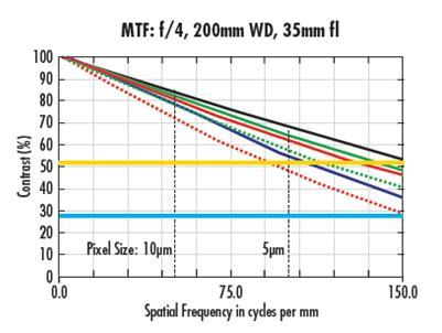
32 How Does Contrast Depend On Frequency? Suppose two dots are placed close to each other and imaged through a lens. The two spots will blur slightly. Moving the spots closer causes the blur to overlap and contrast is decreased. When the spots are close enough that the contrast becomes limiting, the spacing is our resolution. At each spacing of the spots we obtain a specific contrast. We can plot this information in the form of a Modulation Transfer Function (MTF).

33 Lens Comparison Testing - Ronchi Ruling
34 Lens #1 Test 16mm Ronchi Test, 1.5 inch FOV 4 lp/mm object space resolution, pmag, f1.4 Center 59% Bottom Middle 56% Corner 62% F Inch FOV Center Bottom Corner
35 Lens #2 Test 16mm Ronchi Test, 1.5 inch FOV 4 lp/mm object space resolution, pmag, f1.4 Center 47% Bottom Middle 42% Corner 37% F Inch FOV Value Value Value
36 Lens #3 Test 16mm Ronchi Test, 1.5 inch FOV 4 lp/mm object space resolution, pmag, f1.4 Center 52% Bottom Middle 22% Corner 36% F inch FOV Center Bottom 100 Corner
37 Image Comparison F1.4 Center Bottom Middle Corner Lens 1 Lens 2 Lens 3

38 Frequency and Modulation Transfer Function (MTF)
39 Modulation Transfer Function (MTF) Curve
40 What is a Better MTF? Depends on the application. Depends on the detector. Is limiting resolution important? Is high contrast at low frequencies important?

41 Are Lenses The Only Things With MTF s? Each component of an imaging system has an MTF associated with it. Cameras, cables, monitor, capture boards, and eyes all have MTFs. Below is an example of the MTF of a typical CCD camera.

42 How Do Individual MTFs Form a System MTF? A rough estimate of system resolution can be found using the weakest link. This assumes that the system resolution will be determined by the lowest resolution of its components. A more accurate system resolution is one where the MTFs of each component are looked at and combined as a whole. Each component has its own MTF (Lens, camera, cables, capture board, and monitor). By multiplying each MTF we get a System MTF.
43 What Else Can Affect MTF? Many things Aberrations Working distance Wavelength F/#

44 Aberrations The complexity of a design allows for its ability to overcome aberrations Glass materials, number of elements, tolerances all affect aberration control Price to performance ratio is a driving factor 2 different 12mm lenses compared for aberrational control

45 The Star Target Another common target is the star target. Circular pattern of black and white wedges. Radial pattern allows tests of astigmatic errors. Wedges have continuous frequencies that can be calculated by radial distance.


46 Star Target Image Quality Test Lens 1 Lens 2
47 Working Distance Lens are designed for a limited range of working distances Generally the narrower the working distance range that a lens is designed for the higher the performance that can be achieved in that range Price to performance ratio is still a driving factor
48 What Is F/#? Different definitions of F/# Infinite conjugate F/# = Focal length/ Diameter Image Space close conjugate F/# = Image distance/ Diameter Object Space close conjugate F/# = Object distance/ Diameter The same lens used at infinite conjugate and close conjugate will have a lower close conjugate F/# than infinite conjugate F/# *By conjugate, we mean spacing between Object and the lens, an infinite conjugate lens has collimated light entering it.
49 How Does Diffraction and F/# Affect Performance? Not even a perfectly designed and manufactured lens can accurately reproduce an object s detail and contrast. Diffraction will limit the performance of an ideal lens. The size of the aperture will affect the diffraction limit of a lens. The smallest achievable spot of a lens = 2.44 x wavelength of light x (F/#) F/# describes the light gathering ability of an imaging lens (lower F/# lenses collect more light). As lens aperture decreases, F/# increases.
50 Is Diffraction Always the Limiting Factor in a Lens? Diffraction is not the only cause of image resolution and contrast decreasing. Many lenses do not operate at the diffraction limit. Optical errors (aberrations) and manufacturing tolerances often limit performance. Often the performance of a non-diffraction is limited. It can be improved by increasing its F/#, until it is diffraction limited.

51 Working Distance vs. F/#
52 Does Increasing the F/# Always Improve Performance?
53 Resolution vs. F/#, Typical 6mm Lens

54 How is MTF Affected by Wavelength? Chromatic Aberration Chromatic aberrations can be both on axis and off axis Lateral Color Axial Color


55 How is MTF Affected by Wavelength? 660nm Light 3b 470nm Light
56 How is MTF Affected by Wavelength? Using monochromatic illumination instead of white light generally improves performance. Short wavelengths are not always better 3a 3b
57 The Perfect Lens What do the Laws of Physics limits look like on your sensor? This lens does not exist on the commercial market and cannot be made under normal manufacturing conditions Wavelength and F# to be analyzed simultaneously
58 How Wavelength Affects Resolution

59 How Wavelength Affects Resolution
60 How Wavelength Affects Resolution
61 How Wavelength Affects Resolution
62 How Wavelength Affects Resolution

63 How Wavelength Affects Resolution
64 A Real Lens, a Reasonably Good One What does a real lens, a good one, looks like on your sensor This lens fundamentally does exist on the commercial market and can be made under normal yet robust manufacturing conditions A very good design and tight manufacturing tolerances are required Wavelength, F#, center and corner of the sensor to be analyzed simultaneously
65 F2.8
66 F5.6
67 F8
68 Review of Basics Image Quality Resolution MTF Defined at a Resolution and Contrast Depth of Field Image Quality Contrast Perspective Distortion

69 How Can Apertures be Used to Improve Depth of Field? If we express our resolution as an angularly allowable blur ( ) we can define depth of field geometrically. Below we see how two lenses with different F/#s have very different DOF values. Illustration adapted from Smith, Modern Optical Engineering: The Design Of Optical Systems, New York, McGraw-Hill, 1990
70 How Can Apertures be Used to Improve Depth of Field?
71 How Can Apertures be Used to Improve Depth of Field?

72 DOF Resolution Comparison
73 Depth of Field Curves, Changing F/# and WD
74 Depth of Field Points to Remember The depth of field (DOF) of a lens is its ability to maintain a desired amount of image quality as the object is moved from best focus position. DOF also applies to objects with depth, since a lens with high DOF will allow the whole object to be imaged clearly. As the object is moved either closer or further than the working distance, both contrast and resolution suffer. The amount of depth must be defined at both a contrast and a resolution.
75 More Points to Remember DOF is often calculated using diffraction limit, however this is often flawed if the lens is not working at the diffraction limit. Increasing the F/# to increase the depth of field may limit the overall resolution of the imaging system. Therefore, the application constraints must be considered. An alternative to calculating DOF is to test it for the specific resolution and contrast for an application. Changing the F/# can also have effects on the relative illumination of the image obtained.


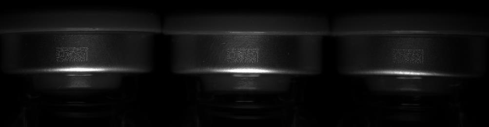
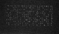
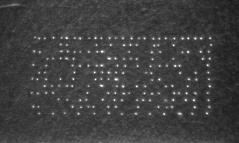
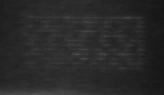
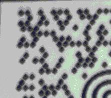
76 How Do We Test Depth of Field? By measuring the size of the portion of the target that meets or exceeds the contrast requirements, depth can be tested. To the left is an image of DOF test target, object space resolution being tested is 15 lp/mm at a contrast of less than 10%. We can either see visually where the image blurs out or we can look at a line spread function and calculate contrast from the grayscale values.
77 Case Study Effects on resolution and depth of field with changing aperture setting Example 1: 8.5mm fixed focal length lens Iris completely open Iris half open Iris mostly closed

78 Case Study Effects on resolution and depth of field with changing aperture setting Example 1: 8.5mm fixed focal length lens Iris completely open Iris half open Iris mostly closed

79 Case Study Effects on resolution and depth of field with changing aperture setting Example 1: 50mm Double Gauss lens Iris completely open Iris half open Iris mostly closed

80 Case Study Effects on resolution and depth of field with changing aperture setting Example 1: 50mm Double Gauss lens Iris completely open Iris half open Iris mostly closed
81 Review of Basics Image Quality Resolution MTF Defined at a Resolution and Contrast Depth of Field Image Quality Contrast Perspective Distortion 2D
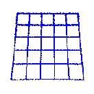
82 Distortion Nature of Distortion: Geometric Aberration - No information is lost (except due to detector resolution limits) Not necessarily monotonic Consistency across manufacturing Rule of Thumb: 2-3% Visually undetectable

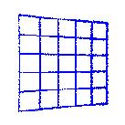
83 How is Distortion Measured? % Distortion = (AD-PD) x 100 PD Above is an example of negative distortion. AD is Actual Distance that an image point is from center of the field. PD is the Predicted Distance that an image point would be from the center of the field if no distortion were present.
84 Specifying Distortion Percent Distortion at the extreme edge of the field is used to determine maximum distortion in a lens. Distortion changes with image position so to accurately predict the effects of distortion a plot of % distortion vs. distance from center of the image. Below is a typical distortion. Distortion exists in all lenses but, can be fairly well corrected. It s more difficult to correct for this aberration in short focal length(wide angle) lenses. Be aware of the difference between TV and Geometric Distortion
85 Distortion Monotonic?

86 Distortion Types of Distortion Symmetric Pincushion Asymmetric Barrel Keystone


, change")
87 Distortion Keystone Introduced because of weird Scheimpflug condition great focus (longitudinal magnification), change in magnification with field


88 How Can Distortion Be Corrected? Software can be used to correct for distortion because no information was lost only misplaced. By knowing how far the information was misplaced software can be used to replace the information in the correct position. Above is an image from a 4.3mm video, first without any software correction, then with distortion removed with software.
89 Review of Basics Image Quality Resolution MTF Defined at a Resolution and Contrast Depth of Field Image Quality Contrast Perspective 3D Distortion 2D

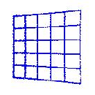
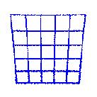
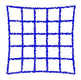
90 What is Perspective Error? Perspective error, also called parallax, is change in magnification with a change in working distance. This is how we perceive distance with our eyes. Objects that are far away appear smaller then objects close up. Though useful for perceiving distance, this is harmful when trying to make measurements. Telecentric lenses are designed to minimize perspective error. Illustration on the right shows the difference in images in a telecentric and conventional lens.
91 Examples of Telecentric Error Test piece is the depth of field target looking at the parallel lines running down the 45 degree target. Telecentricity is demonstrated by the line converging as they get farther from the lens.

92 Measurement with a Telecentric Lens

93 Measurement with a Non-Telecentric Lens Telecentric error

94 Comparison Telecentric to Non-Telecentric Lenses As can be seen in the diagram, as working distance increases magnification decreases for the conventional lens In the telecentric lens magnification is maintained

95 Telecentric Lenses are Useful in Many Applications Even when the image is out of focus a Telecentric lens can be very useful because there is no change in magnification with working distance equal burring will occur. This allows for accurate center potions to be determined. Telecentric Lens Conventional Lens
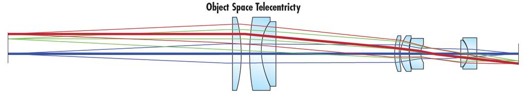
96 Why Does Perspective Error Occur? Chief ray= ray that goes through the center of the aperture stop. Off axis chief ray On axis chief ray In a conventional lens the angle between chief rays at different image heights causes the parallax error. Off axis chief ray On axis chief ray In a telecentric lens, the chief rays are all parallel.
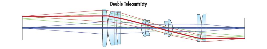
97 Types of Telecentric Lenses

98 What are the Limitations of Telecentric Lenses? The telecentric field of view of a telecentric lens is limited by the diameter of the front lens. The need for the chief rays to be parallel constrains the telecentric region to be smaller than the lens diameter. All telecentric lenses can only meet their telecentric specifications over a specific range of working distances. Because magnification is constant for a telecentric lens, different lenses are needed for different fields of view.
99 Review of Basics Image Quality Resolution Depth of Field Contrast Defined at a Resolution and Contrast Image Quality Perspective Distortion
100 Finally, Do your Homework! Optics can process images at the speed of light. Give it the time it deserves! Specify what you need as a system not just components. Expect a lot from optical suppliers. They should know much more then just lens design.
101 Suggested Texts for Further Information on Image Quality Smith, Modern Optical Engineering: The Design Of Optical Systems, New York, McGraw-Hill, 1990 Shannon, The Art and Science of Optical Design, Massachusetts, Cambridge University, 1997 Optikos Corp., How to measure MTF PDF file
 547-3488 Email: ghollows@edmundoptics.com www.")
102 Gregory Hollows Director, Imaging Business Unit Edmund Optics 101 East Gloucester Pike Barrington, New Jersey USA Phone: (856)
BIG PIXELS VS. SMALL PIXELS THE OPTICAL BOTTLENECK. Gregory Hollows Edmund Optics
 BIG PIXELS VS. SMALL PIXELS THE OPTICAL BOTTLENECK Gregory Hollows Edmund Optics 1 IT ALL STARTS WITH THE SENSOR We have to begin with sensor technology to understand the road map Resolution will continue
Using Optics to Optimize Your Machine Vision Application
 Expert Guide Using Optics to Optimize Your Machine Vision Application Introduction The lens is responsible for creating sufficient image quality to enable the vision system to extract the desired information
TECHSPEC COMPACT FIXED FOCAL LENGTH LENS
 Designed for use in machine vision applications, our TECHSPEC Compact Fixed Focal Length Lenses are ideal for use in factory automation, inspection or qualification. These machine vision lenses have been
IMAGE SENSOR SOLUTIONS. KAC-96-1/5" Lens Kit. KODAK KAC-96-1/5" Lens Kit. for use with the KODAK CMOS Image Sensors. November 2004 Revision 2
 KODAK for use with the KODAK CMOS Image Sensors November 2004 Revision 2 1.1 Introduction Choosing the right lens is a critical aspect of designing an imaging system. Typically the trade off between image
Overview: Integration of Optical Systems Survey on current optical system design Case demo of optical system design
 Outline Chapter 1: Introduction Overview: Integration of Optical Systems Survey on current optical system design Case demo of optical system design 1 Overview: Integration of optical systems Key steps
Chapter 25 Optical Instruments
 Chapter 25 Optical Instruments Units of Chapter 25 Cameras, Film, and Digital The Human Eye; Corrective Lenses Magnifying Glass Telescopes Compound Microscope Aberrations of Lenses and Mirrors Limits of
Optical design of a high resolution vision lens
 Optical design of a high resolution vision lens Paul Claassen, optical designer, paul.claassen@sioux.eu Marnix Tas, optical specialist, marnix.tas@sioux.eu Prof L.Beckmann, l.beckmann@hccnet.nl Summary:
Optical basics for machine vision systems. Lars Fermum Chief instructor STEMMER IMAGING GmbH
 Optical basics for machine vision systems Lars Fermum Chief instructor STEMMER IMAGING GmbH www.stemmer-imaging.de AN INTERNATIONAL CONCEPT STEMMER IMAGING customers in UK Germany France Switzerland Sweden
Opto Engineering S.r.l.
 TUTORIAL #1 Telecentric Lenses: basic information and working principles On line dimensional control is one of the most challenging and difficult applications of vision systems. On the other hand, besides
Geometric optics & aberrations
 Geometric optics & aberrations Department of Astrophysical Sciences University AST 542 http://www.northerneye.co.uk/ Outline Introduction: Optics in astronomy Basics of geometric optics Paraxial approximation
ECEN 4606, UNDERGRADUATE OPTICS LAB
 ECEN 4606, UNDERGRADUATE OPTICS LAB Lab 2: Imaging 1 the Telescope Original Version: Prof. McLeod SUMMARY: In this lab you will become familiar with the use of one or more lenses to create images of distant
Laboratory experiment aberrations
 Laboratory experiment aberrations Obligatory laboratory experiment on course in Optical design, SK2330/SK3330, KTH. Date Name Pass Objective This laboratory experiment is intended to demonstrate the most
Chapter 25. Optical Instruments
 Chapter 25 Optical Instruments Optical Instruments Analysis generally involves the laws of reflection and refraction Analysis uses the procedures of geometric optics To explain certain phenomena, the wave
Optical Components for Laser Applications. Günter Toesko - Laserseminar BLZ im Dezember
 Günter Toesko - Laserseminar BLZ im Dezember 2009 1 Aberrations An optical aberration is a distortion in the image formed by an optical system compared to the original. It can arise for a number of reasons
Lecture PowerPoint. Chapter 25 Physics: Principles with Applications, 6 th edition Giancoli
 Lecture PowerPoint Chapter 25 Physics: Principles with Applications, 6 th edition Giancoli 2005 Pearson Prentice Hall This work is protected by United States copyright laws and is provided solely for the
Optics: An Introduction
 It is easy to overlook the contribution that optics make to a system; beyond basic lens parameters such as focal distance, the details can seem confusing. This Tech Tip presents a basic guide to optics
Performance Factors. Technical Assistance. Fundamental Optics
 Performance Factors After paraxial formulas have been used to select values for component focal length(s) and diameter(s), the final step is to select actual lenses. As in any engineering problem, this
Variable microinspection system. system125
 Variable microinspection system system125 Variable micro-inspection system Characteristics Large fields, high NA The variable microinspection system mag.x system125 stands out from conventional LD inspection
mm F2.6 6MP IR-Corrected. Sensor size
 1 1 inch and 1/1.2 inch image size spec. Sensor size 1-inch 1/1.2-inch 2/3-inch Image circle OK OK OK OK 1/1.8-inch OK 1/2-inch OK 1/2.5-inch 1 1-inch CMV4000 PYTHON5000 KAI-02150 KAI-2020 KAI-2093 KAI-4050
Lecture 2: Geometrical Optics. Geometrical Approximation. Lenses. Mirrors. Optical Systems. Images and Pupils. Aberrations.
 Lecture 2: Geometrical Optics Outline 1 Geometrical Approximation 2 Lenses 3 Mirrors 4 Optical Systems 5 Images and Pupils 6 Aberrations Christoph U. Keller, Leiden Observatory, keller@strw.leidenuniv.nl
Topic 6 - Optics Depth of Field and Circle Of Confusion
 Topic 6 - Optics Depth of Field and Circle Of Confusion Learning Outcomes In this lesson, we will learn all about depth of field and a concept known as the Circle of Confusion. By the end of this lesson,
There is a range of distances over which objects will be in focus; this is called the depth of field of the lens. Objects closer or farther are
 Chapter 25 Optical Instruments Some Topics in Chapter 25 Cameras The Human Eye; Corrective Lenses Magnifying Glass Telescopes Compound Microscope Aberrations of Lenses and Mirrors Limits of Resolution
MML-High Resolution 5M Series
 Fixed Magnification Series -High Resolution 5M Series High-resolution models that possess the best contrast and NA of all Series. Image acquisition with even higher image quality is realized by combining
PHYSICS. Chapter 35 Lecture FOR SCIENTISTS AND ENGINEERS A STRATEGIC APPROACH 4/E RANDALL D. KNIGHT
 PHYSICS FOR SCIENTISTS AND ENGINEERS A STRATEGIC APPROACH 4/E Chapter 35 Lecture RANDALL D. KNIGHT Chapter 35 Optical Instruments IN THIS CHAPTER, you will learn about some common optical instruments and
Lecture 2: Geometrical Optics. Geometrical Approximation. Lenses. Mirrors. Optical Systems. Images and Pupils. Aberrations.
 Lecture 2: Geometrical Optics Outline 1 Geometrical Approximation 2 Lenses 3 Mirrors 4 Optical Systems 5 Images and Pupils 6 Aberrations Christoph U. Keller, Leiden Observatory, keller@strw.leidenuniv.nl
Opti 415/515. Introduction to Optical Systems. Copyright 2009, William P. Kuhn
 Opti 415/515 Introduction to Optical Systems 1 Optical Systems Manipulate light to form an image on a detector. Point source microscope Hubble telescope (NASA) 2 Fundamental System Requirements Application
ME 297 L4-2 Optical design flow Analysis
 ME 297 L4-2 Optical design flow Analysis Nayer Eradat Fall 2011 SJSU 1 Are we meeting the specs? First order requirements (after scaling the lens) Distortion Sharpness (diffraction MTF-will establish depth
Using molded chalcogenide glass technology to reduce cost in a compact wide-angle thermal imaging lens
 Using molded chalcogenide glass technology to reduce cost in a compact wide-angle thermal imaging lens George Curatu a, Brent Binkley a, David Tinch a, and Costin Curatu b a LightPath Technologies, 2603
Waves & Oscillations
 Physics 42200 Waves & Oscillations Lecture 33 Geometric Optics Spring 2013 Semester Matthew Jones Aberrations We have continued to make approximations: Paraxial rays Spherical lenses Index of refraction
Exam Preparation Guide Geometrical optics (TN3313)
") Exam Preparation Guide Geometrical optics (TN3313) Lectures: September - December 2001 Version of 21.12.2001 When preparing for the exam, check on Blackboard for a possible newer version of this guide.
Exam Preparation Guide Geometrical optics (TN3313) Lectures: September - December 2001 Version of 21.12.2001 When preparing for the exam, check on Blackboard for a possible newer version of this guide.
Chapters 1 & 2. Definitions and applications Conceptual basis of photogrammetric processing
 Chapters 1 & 2 Chapter 1: Photogrammetry Definitions and applications Conceptual basis of photogrammetric processing Transition from two-dimensional imagery to three-dimensional information Automation
Lecture 8. Lecture 8. r 1
 Lecture 8 Achromat Design Design starts with desired Next choose your glass materials, i.e. Find P D P D, then get f D P D K K Choose radii (still some freedom left in choice of radii for minimization
CODE V Introductory Tutorial
 CODE V Introductory Tutorial Cheng-Fang Ho Lab.of RF-MW Photonics, Department of Physics, National Cheng-Kung University, Tainan, Taiwan 1-1 Tutorial Outline Introduction to CODE V Optical Design Process
Lecture 4: Geometrical Optics 2. Optical Systems. Images and Pupils. Rays. Wavefronts. Aberrations. Outline
 Lecture 4: Geometrical Optics 2 Outline 1 Optical Systems 2 Images and Pupils 3 Rays 4 Wavefronts 5 Aberrations Christoph U. Keller, Leiden University, keller@strw.leidenuniv.nl Lecture 4: Geometrical
IMAGE FORMATION. Light source properties. Sensor characteristics Surface. Surface reflectance properties. Optics
 IMAGE FORMATION Light source properties Sensor characteristics Surface Exposure shape Optics Surface reflectance properties ANALOG IMAGES An image can be understood as a 2D light intensity function f(x,y)
Introduction to Light Microscopy. (Image: T. Wittman, Scripps)
") Introduction to Light Microscopy (Image: T. Wittman, Scripps) The Light Microscope Four centuries of history Vibrant current development One of the most widely used research tools A. Khodjakov et al. Major
Introduction to Light Microscopy (Image: T. Wittman, Scripps) The Light Microscope Four centuries of history Vibrant current development One of the most widely used research tools A. Khodjakov et al. Major
TSBB09 Image Sensors 2018-HT2. Image Formation Part 1
 TSBB09 Image Sensors 2018-HT2 Image Formation Part 1 Basic physics Electromagnetic radiation consists of electromagnetic waves With energy That propagate through space The waves consist of transversal
Cameras. Steve Rotenberg CSE168: Rendering Algorithms UCSD, Spring 2017
 Cameras Steve Rotenberg CSE168: Rendering Algorithms UCSD, Spring 2017 Camera Focus Camera Focus So far, we have been simulating pinhole cameras with perfect focus Often times, we want to simulate more
Optical and mechanical parameters. 100 mm N. of elements 20.5 mm Dimensions 11.7 degrees Weight F/N = 4 (fixed) N.A.
 N.A.") OB SWIR 100 LENS OB-SWIR100/4 P/N C0416 General Description This family of high resolution SWIR lenses image from 0.9 2.3 µmm making them especially well-suited for PCB inspection, special laser applications,
OB SWIR 100 LENS OB-SWIR100/4 P/N C0416 General Description This family of high resolution SWIR lenses image from 0.9 2.3 µmm making them especially well-suited for PCB inspection, special laser applications,
Criteria for Optical Systems: Optical Path Difference How do we determine the quality of a lens system? Several criteria used in optical design
 Criteria for Optical Systems: Optical Path Difference How do we determine the quality of a lens system? Several criteria used in optical design Computer Aided Design Several CAD tools use Ray Tracing (see
Speed and Image Brightness uniformity of telecentric lenses
 Specialist Article Published by: elektronikpraxis.de Issue: 11 / 2013 Speed and Image Brightness uniformity of telecentric lenses Author: Dr.-Ing. Claudia Brückner, Optics Developer, Vision & Control GmbH
Notes from Lens Lecture with Graham Reed
 Notes from Lens Lecture with Graham Reed Light is refracted when in travels between different substances, air to glass for example. Light of different wave lengths are refracted by different amounts. Wave
LENSES. INEL 6088 Computer Vision
 LENSES INEL 6088 Computer Vision Digital camera A digital camera replaces film with a sensor array Each cell in the array is a Charge Coupled Device light-sensitive diode that converts photons to electrons
Unit 1: Image Formation
 Unit 1: Image Formation 1. Geometry 2. Optics 3. Photometry 4. Sensor Readings Szeliski 2.1-2.3 & 6.3.5 1 Physical parameters of image formation Geometric Type of projection Camera pose Optical Sensor
INFLUENCE OF VARIABLE APERTURE STOP
 INFLUENCE OF VARIABLE APERTURE STOP IN TELECENTRIC IMAGING LENSES SILL OPTICS GMBH CO. KG TECHNOLOGY FORUM MACHINE VISION 2015/16 Konrad Hentschel, Dipl-Phys. Andreas Platz, M.Sc. Project Management CONTENT
The Importance of Wavelengths on Optical Designs
 1 The Importance of Wavelengths on Optical Designs Bad Kreuznach, Oct. 2017 2 Introduction A lens typically needs to be corrected for many different parameters as e.g. distortion, astigmatism, spherical
Study on Imaging Quality of Water Ball Lens
 2017 2nd International Conference on Mechatronics and Information Technology (ICMIT 2017) Study on Imaging Quality of Water Ball Lens Haiyan Yang1,a,*, Xiaopan Li 1,b, 1,c Hao Kong, 1,d Guangyang Xu and1,eyan
Be aware that there is no universal notation for the various quantities.
 Fourier Optics v2.4 Ray tracing is limited in its ability to describe optics because it ignores the wave properties of light. Diffraction is needed to explain image spatial resolution and contrast and
 Telecentric Imaging Object space telecentricity stop source: edmund optics The 5 classical Seidel Aberrations First order aberrations Spherical Aberration (~r 4 ) Origin: different focal lengths for different
Chapter 3 Op,cal Instrumenta,on
 Imaging by an Op,cal System Change in curvature of wavefronts by a thin lens Chapter 3 Op,cal Instrumenta,on 3-1 Stops, Pupils, and Windows 3-4 The Camera 3-5 Simple Magnifiers and Eyepieces 1. Magnifiers
Compact camera module testing equipment with a conversion lens
 Compact camera module testing equipment with a conversion lens Jui-Wen Pan* 1 Institute of Photonic Systems, National Chiao Tung University, Tainan City 71150, Taiwan 2 Biomedical Electronics Translational
Chapter 3 Op+cal Instrumenta+on
 Chapter 3 Op+cal Instrumenta+on 3-1 Stops, Pupils, and Windows 3-4 The Camera 3-5 Simple Magnifiers and Eyepieces 3-6 Microscopes 3-7 Telescopes Today (2011-09-22) 1. Magnifiers 2. Camera 3. Resolution
Resolving Power of a Diffraction Grating
 Resolving Power of a Diffraction Grating When measuring wavelengths, it is important to distinguish slightly different s. The ability of a grating to resolve the difference in wavelengths is given by the
Image Formation and Capture. Acknowledgment: some figures by B. Curless, E. Hecht, W.J. Smith, B.K.P. Horn, and A. Theuwissen
 Image Formation and Capture Acknowledgment: some figures by B. Curless, E. Hecht, W.J. Smith, B.K.P. Horn, and A. Theuwissen Image Formation and Capture Real world Optics Sensor Devices Sources of Error
On spatial resolution
 On spatial resolution Introduction How is spatial resolution defined? There are two main approaches in defining local spatial resolution. One method follows distinction criteria of pointlike objects (i.e.
Vision. The eye. Image formation. Eye defects & corrective lenses. Visual acuity. Colour vision. Lecture 3.5
 Lecture 3.5 Vision The eye Image formation Eye defects & corrective lenses Visual acuity Colour vision Vision http://www.wired.com/wiredscience/2009/04/schizoillusion/ Perception of light--- eye-brain
Telecentric lenses.
 Telecentric lenses 2014 Bi-Telecentric lenses Titolo Index Descrizione Telecentric lenses Opto Engineering Telecentric lenses represent our core business: these products benefit from a decade-long effort
OPTICAL SYSTEMS OBJECTIVES
 101 L7 OPTICAL SYSTEMS OBJECTIVES Aims Your aim here should be to acquire a working knowledge of the basic components of optical systems and understand their purpose, function and limitations in terms
CHAPTER 33 ABERRATION CURVES IN LENS DESIGN
 CHAPTER 33 ABERRATION CURVES IN LENS DESIGN Donald C. O Shea Georgia Institute of Technology Center for Optical Science and Engineering and School of Physics Atlanta, Georgia Michael E. Harrigan Eastman
Image Formation III Chapter 1 (Forsyth&Ponce) Cameras Lenses & Sensors
 Cameras Lenses & Sensors") Image Formation III Chapter 1 (Forsyth&Ponce) Cameras Lenses & Sensors Guido Gerig CS-GY 6643, Spring 2017 (slides modified from Marc Pollefeys, UNC Chapel Hill/ ETH Zurich, With content from Prof. Trevor
Image Formation III Chapter 1 (Forsyth&Ponce) Cameras Lenses & Sensors Guido Gerig CS-GY 6643, Spring 2017 (slides modified from Marc Pollefeys, UNC Chapel Hill/ ETH Zurich, With content from Prof. Trevor
ORIFICE MEASUREMENT VERISENS APPLICATION DESCRIPTION: REQUIREMENTS APPLICATION CONSIDERATIONS RESOLUTION/ MEASUREMENT ACCURACY. Vision Technologies
 VERISENS APPLICATION DESCRIPTION: ORIFICE MEASUREMENT REQUIREMENTS A major manufacturer of plastic orifices needs to verify that the orifice is within the correct measurement band. Parts are presented
LENS OB-SWIR500/7 P/N C0615
 LENS OB-SWIR500/7 P/N C0615 General Description This family of high resolution SWIR lenses image from 0.9 2.3 m making them especially well-suited for PCB inspection, special laser applications, surveillance
Systems Biology. Optical Train, Köhler Illumination
 McGill University Life Sciences Complex Imaging Facility Systems Biology Microscopy Workshop Tuesday December 7 th, 2010 Simple Lenses, Transmitted Light Optical Train, Köhler Illumination What Does a
VC 11/12 T2 Image Formation
 VC 11/12 T2 Image Formation Mestrado em Ciência de Computadores Mestrado Integrado em Engenharia de Redes e Sistemas Informáticos Miguel Tavares Coimbra Outline Computer Vision? The Human Visual System
How to Choose a Machine Vision Camera for Your Application.
 Vision Systems Design Webinar 9 September 2015 How to Choose a Machine Vision Camera for Your Application. Andrew Bodkin Bodkin Design & Engineering, LLC Newton, MA 02464 617-795-1968 wab@bodkindesign.com
ECEN 4606, UNDERGRADUATE OPTICS LAB
 ECEN 4606, UNDERGRADUATE OPTICS LAB Lab 3: Imaging 2 the Microscope Original Version: Professor McLeod SUMMARY: In this lab you will become familiar with the use of one or more lenses to create highly
Lecture Outline Chapter 27. Physics, 4 th Edition James S. Walker. Copyright 2010 Pearson Education, Inc.
 Lecture Outline Chapter 27 Physics, 4 th Edition James S. Walker Chapter 27 Optical Instruments Units of Chapter 27 The Human Eye and the Camera Lenses in Combination and Corrective Optics The Magnifying
INTRODUCTION THIN LENSES. Introduction. given by the paraxial refraction equation derived last lecture: Thin lenses (19.1) = 1. Double-lens systems
 = 1. Double-lens systems") Chapter 9 OPTICAL INSTRUMENTS Introduction Thin lenses Double-lens systems Aberrations Camera Human eye Compound microscope Summary INTRODUCTION Knowledge of geometrical optics, diffraction and interference,
Chapter 9 OPTICAL INSTRUMENTS Introduction Thin lenses Double-lens systems Aberrations Camera Human eye Compound microscope Summary INTRODUCTION Knowledge of geometrical optics, diffraction and interference,
A Micro Scale Measurement by Telecentric Digital-Micro-Imaging Module Coupled with Projection Pattern
 Available online at www.sciencedirect.com Physics Procedia 19 (2011) 265 270 ICOPEN 2011 A Micro Scale Measurement by Telecentric Digital-Micro-Imaging Module Coupled with Projection Pattern Kuo-Cheng
Optical System Design
 Phys 531 Lecture 12 14 October 2004 Optical System Design Last time: Surveyed examples of optical systems Today, discuss system design Lens design = course of its own (not taught by me!) Try to give some
Advanced Optics for Vision. Stuart W. Singer Sr. Vice President & CTO Schneider Optics, Inc.
 Advanced Optics for Vision Stuart W. Singer Sr. Vice President & CTO Schneider Optics, Inc. Table of Contents Modulation Transfer Function (MTF) What does it mean Aberration effects f/number effects Manufacturing
Applications of Optics
 Nicholas J. Giordano www.cengage.com/physics/giordano Chapter 26 Applications of Optics Marilyn Akins, PhD Broome Community College Applications of Optics Many devices are based on the principles of optics
Chapter 36. Image Formation
 Chapter 36 Image Formation Image of Formation Images can result when light rays encounter flat or curved surfaces between two media. Images can be formed either by reflection or refraction due to these
Lens Design II. Lecture 11: Further topics Herbert Gross. Winter term
 Lens Design II Lecture : Further topics 28--8 Herbert Gross Winter term 27 www.iap.uni-ena.de 2 Preliminary Schedule Lens Design II 27 6.. Aberrations and optimization Repetition 2 23.. Structural modifications
Chapter 36. Image Formation
 Chapter 36 Image Formation Notation for Mirrors and Lenses The object distance is the distance from the object to the mirror or lens Denoted by p The image distance is the distance from the image to the
Overview. Pinhole camera model Projective geometry Vanishing points and lines Projection matrix Cameras with Lenses Color Digital image
 Camera & Color Overview Pinhole camera model Projective geometry Vanishing points and lines Projection matrix Cameras with Lenses Color Digital image Book: Hartley 6.1, Szeliski 2.1.5, 2.2, 2.3 The trip
LENS ZOOM-SWIR 7x P/N C0628
 ZOOM SWIR 7x LENS ZOOM-SWIR 7x P/N C0628 General Description This family of high resolution SWIR lenses image from 0.9 2.3 m making them especially well-suited for PCB inspection, special laser applications,
New foveated wide angle lens with high resolving power and without brightness loss in the periphery
 New foveated wide angle lens with high resolving power and without brightness loss in the periphery K. Wakamiya *a, T. Senga a, K. Isagi a, N. Yamamura a, Y. Ushio a and N. Kita b a Nikon Corp., 6-3,Nishi-ohi
Heisenberg) relation applied to space and transverse wavevector
 relation applied to space and transverse wavevector") 2. Optical Microscopy 2.1 Principles A microscope is in principle nothing else than a simple lens system for magnifying small objects. The first lens, called the objective, has a short focal length (a
2. Optical Microscopy 2.1 Principles A microscope is in principle nothing else than a simple lens system for magnifying small objects. The first lens, called the objective, has a short focal length (a
Cameras. CSE 455, Winter 2010 January 25, 2010
 Cameras CSE 455, Winter 2010 January 25, 2010 Announcements New Lecturer! Neel Joshi, Ph.D. Post-Doctoral Researcher Microsoft Research neel@cs Project 1b (seam carving) was due on Friday the 22 nd Project
Measurement of the Modulation Transfer Function (MTF) of a camera lens. Laboratoire d Enseignement Expérimental (LEnsE)
 of a camera lens. Laboratoire d Enseignement Expérimental (LEnsE)") Measurement of the Modulation Transfer Function (MTF) of a camera lens Aline Vernier, Baptiste Perrin, Thierry Avignon, Jean Augereau, Lionel Jacubowiez Institut d Optique Graduate School Laboratoire d
Measurement of the Modulation Transfer Function (MTF) of a camera lens Aline Vernier, Baptiste Perrin, Thierry Avignon, Jean Augereau, Lionel Jacubowiez Institut d Optique Graduate School Laboratoire d
Modulation Transfer Function
 Modulation Transfer Function The Modulation Transfer Function (MTF) is a useful tool in system evaluation. t describes if, and how well, different spatial frequencies are transferred from object to image.
Physics 1230: Light and Color. Guest Lecture, Jack again. Lecture 23: More about cameras
 Physics 1230: Light and Color Chuck Rogers, Charles.Rogers@colorado.edu Ryan Henley, Valyria McFarland, Peter Siegfried physicscourses.colorado.edu/phys1230 Guest Lecture, Jack again Lecture 23: More about
Basler Accessories. Technical Specification BASLER LENS C M. Order Number
 Basler Accessories Technical Specification BASLER LENS C23-526-2M Order Number 22183 Document Number: DG1916 Version: 1 Language: (English) Release Date: 17 January 218 Contacting Basler Support Worldwide
The Camera : Computational Photography Alexei Efros, CMU, Fall 2005
 The Camera 15-463: Computational Photography Alexei Efros, CMU, Fall 2005 How do we see the world? object film Let s design a camera Idea 1: put a piece of film in front of an object Do we get a reasonable
Tangents. The f-stops here. Shedding some light on the f-number. by Marcus R. Hatch and David E. Stoltzmann
 Tangents Shedding some light on the f-number The f-stops here by Marcus R. Hatch and David E. Stoltzmann The f-number has peen around for nearly a century now, and it is certainly one of the fundamental
Some of the important topics needed to be addressed in a successful lens design project (R.R. Shannon: The Art and Science of Optical Design)
") Lens design Some of the important topics needed to be addressed in a successful lens design project (R.R. Shannon: The Art and Science of Optical Design) Focal length (f) Field angle or field size F/number
Lens design Some of the important topics needed to be addressed in a successful lens design project (R.R. Shannon: The Art and Science of Optical Design) Focal length (f) Field angle or field size F/number
PHYSICS FOR THE IB DIPLOMA CAMBRIDGE UNIVERSITY PRESS
 Option C Imaging C Introduction to imaging Learning objectives In this section we discuss the formation of images by lenses and mirrors. We will learn how to construct images graphically as well as algebraically.
7x P/N C1601. General Description
 METRICZOOM SWIR 7x METRIC ZOOM-SWIR ZOOM 7x P/N C1601 C General Description This family of high resolution METRIC ZOOM SWIR lenses image from 0.9 to 2.3 µm making them especially well-suited well for surveillance,
LEICA Summarit-S 70 mm ASPH. f/2.5 / CS
 Technical Data. Illustration 1:2 Technical Data Order no. 1155 (CS: 1151) Image angle (diagonal, horizontal, vertical) approx. 42 / 35 / 24, corresponds to approx. 56 focal length in 35 format Optical
Optical Design with Zemax
 Optical Design with Zemax Lecture : Correction II 3--9 Herbert Gross Summer term www.iap.uni-jena.de Correction II Preliminary time schedule 6.. Introduction Introduction, Zemax interface, menues, file
Building a Real Camera. Slides Credit: Svetlana Lazebnik
 Building a Real Camera Slides Credit: Svetlana Lazebnik Home-made pinhole camera Slide by A. Efros http://www.debevec.org/pinhole/ Shrinking the aperture Why not make the aperture as small as possible?
AST Lab exercise: aberrations
 AST2210 - Lab exercise: aberrations 1 Introduction This lab exercise will take you through the most common types of aberrations. 2 Chromatic aberration Chromatic aberration causes lens to have dierent
Exposure settings & Lens choices
 Exposure settings & Lens choices Graham Relf Tynemouth Photographic Society September 2018 www.tynemouthps.org We will look at the 3 variables available for manual control of digital photos: Exposure time/duration,
Basler Accessories. Technical Specification BASLER LENS C M. Order Number
 Basler Accessories Technical Specification BASLER LENS C23-1616-2M Order Number 2200000180 Document Number: DG001913 Version: 01 Language: 000 (English) Release Date: 17 January 2018 Contacting Basler
Improved Spectra with a Schmidt-Czerny-Turner Spectrograph
 Improved Spectra with a Schmidt-Czerny-Turner Spectrograph Abstract For years spectra have been measured using traditional Czerny-Turner (CT) design dispersive spectrographs. Optical aberrations inherent
Optical Systems: Pinhole Camera Pinhole camera: simple hole in a box: Called Camera Obscura Aristotle discussed, Al-Hazen analyzed in Book of Optics
 Optical Systems: Pinhole Camera Pinhole camera: simple hole in a box: Called Camera Obscura Aristotle discussed, Al-Hazen analyzed in Book of Optics 1011CE Restricts rays: acts as a single lens: inverts
Flatness of Dichroic Beamsplitters Affects Focus and Image Quality
 Flatness of Dichroic Beamsplitters Affects Focus and Image Quality Flatness of Dichroic Beamsplitters Affects Focus and Image Quality 1. Introduction Even though fluorescence microscopy has become a routine
Cardinal Points of an Optical System--and Other Basic Facts
 Cardinal Points of an Optical System--and Other Basic Facts The fundamental feature of any optical system is the aperture stop. Thus, the most fundamental optical system is the pinhole camera. The image
The Camera : Computational Photography Alexei Efros, CMU, Fall 2008
 The Camera 15-463: Computational Photography Alexei Efros, CMU, Fall 2008 How do we see the world? object film Let s design a camera Idea 1: put a piece of film in front of an object Do we get a reasonable