How to Choose a Machine Vision Camera for Your Application.
|
|
|
- Eunice Warren
- 5 years ago
- Views:
Transcription


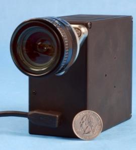
1 Vision Systems Design Webinar 9 September 2015 How to Choose a Machine Vision Camera for Your Application. Andrew Bodkin Bodkin Design & Engineering, LLC Newton, MA wab@bodkindesign.com


2 Bodkin Design and Engineering Specializing in Imaging Systems System-level solutions draw on our expertise in: Optics Photonics Opto-Mechanics Software Spectroscopy Sensors Instrumentation Electrical Engineering Mechanical Engineering Physics 2
3 Machine Vision Measure optical phenomena spatial location (size) reflectivity/absorption color-imaging / spectroscopy stop motion / time studies phase (transparent imaging) self emission (temperature) polarization (stress) 3
4 Front End Common to all these systems are cameras lenses focal length, f/number, spatial resolution, depth of focus, telecentricity, uniformity focal plane array pitch, pixel count, color filter, read out sequence, bit depth, well depth, integration time, dynamic range This webinar will explain how to select the components for the camera to match your application 4
5 Pinhole Imager The fundamental process of imaging A ray of light passes through a pinhole and makes a spot The sum of the spots is an image All other systems are simply improvements on this fundamental imager 5
6 Definitions Magnification=i/o, Pixel field-of-view PFOV (radians) Field-of-view FOV (radians) Footprint (mm) p=pixel pitch horizontal and vertical Pixel footprint (mm) 6
7 Layout of a Thin Lens 1. Light travels left to right 2. Rays leave the object and pass through the lens 3. Rays parallel to the optic axis pass through the back focal point 4. Rays go straight through the center of the lens 5. Rays through the front focal point exit parallel to the optic axis 7
8 First Order Optical Parameters Thin lens formula f=focal length o=object distance i= image distance How to focus the image Magnification How big is the image 8
9 Image Intensity F-number / Numerical Aperture f/=f-number NA=Numerical Aperture ap=aperture diameter ø=edge ray angle at the image 9


10 Depth of Field Image blur spot diameter increases with defocus Is a continuum and is increased by reducing the f-cone Aperture stop Blur spot Blur spot diameter from optical aberrations and diffraction 10
11 Focal Plane Array 2D and linear arrays Color or Monochrome, Bayer filter Pixel pitch Format Pixel count, total count, horizontal x vertical Frame rate Bit depth Progressive Scan (rolling shutter)/framing (global shutter) 11
12 Format Aspect Ratio 4:3, 16:9 1 sensor has 16 mm diagonal (1 OD vidicon tube) Sensor Diagonal Width Height Representative Format (mm) (mm) (mm) Sensor 1/3" Micron MT9M131 1/2" Kodak KAF0400 1/1.8" Sony ICX452 2/3" Sony ICX285 1" Kodak KAI2000 4/3" Kodak KAI4000 Arcane units. Simply multiply pitch by pixel count H x V Diagonal is used to select lens 12
13 Pixel Pitch Common pixel pitch 7.4, 5.5, 5.6, 6.5, 4.7, 3.27, 2.2, 1.6, 1.25 um Small pixels <2.5um are sub blur spot, do not increase resolution b=blur radius λ=wavelength 1.22*.5um*4=2.44um Pixel limited resolution R=resolution (lp/mm) p=pixel pitch (mm) Rated in H x V 1280 x 1024=1.3 MP 13


14 Bayer Filter Monochrome FPA, resolution is 2x pixel pitch Color FPA, Bayer filter reduces resolution by half, 4X pixel pitch Eye spectral sensitivity Native silicon sensitivity Solar illumination FPA spectral sensitivity 14
15 Accuracy Pixel Limited Resolution Optics Limited Resolution Distance = L ± p Distance = L ± b Diffraction limited blur spot 15


16 Optics Resolution Radial spokes Image line scan MTF curve USAF 1951 Test Chart 16

17 System MTF MTF 4" aperture, F/1.6, 17um pixel Diff Ltd MTF Array MTF Total MTF Cycles/mrad Nyquist cut-off Aliasing 17
18 Lens Specification Mounting flange/flange focal distance C-mount / mm CS-mount /12.5 mm SLR lenses proprietary F-mount, Canon, etc. ~ 46.5mm Fixed focus/varifocal/zoom Field diagonal 18


19 Example Maximize magnification Lens outer diameter <75mm Working distance >150mm Fill f/4 cold stop 19

20 Lens Selection Tamron varifocal lenses 20

21 Fixed Focus Lenses Videology 21

22 Megapixel Lenses Fujinon 22
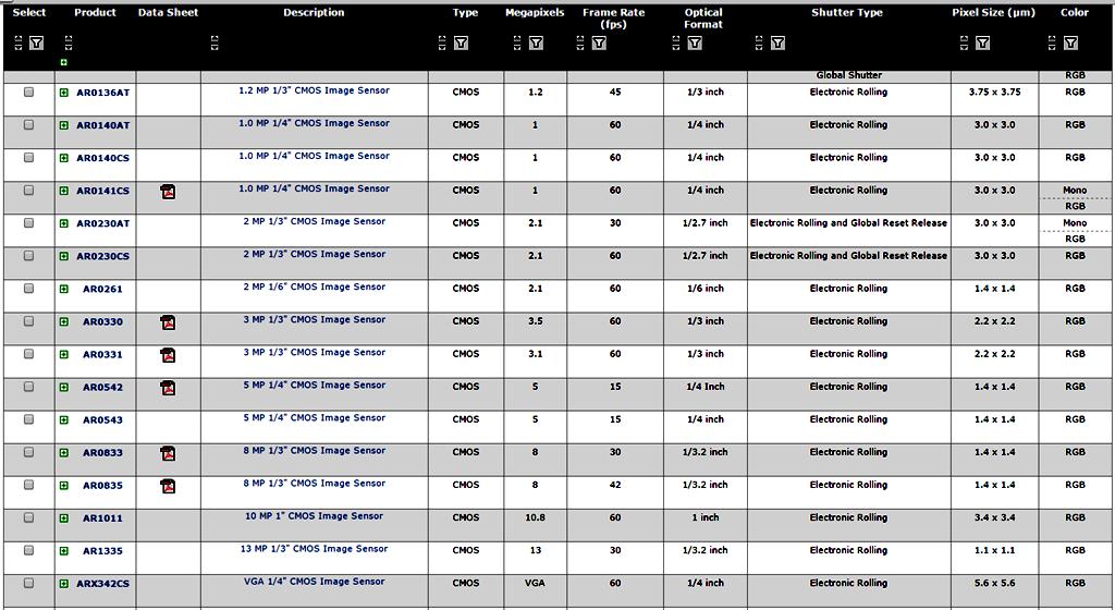
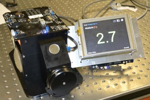
23 FPA selector ON-semiconductor 23
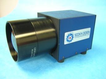
24 Telecentric Lens Defect of focus can cause magnification changes. Not good for metrology. Objects in front of target look bigger than they are. Telecentric system all the cones are parallel. (chief rays are parallel to the optic axis). no magnification change with defocus. Conventional Telecentric 24

25 Scheimpflug Imaging Conventional lens the object plane is perpendicular to the camera lens. Problematic for off-axis imaging Lens tilted to the Scheimpflug condition, the image plane lays down. Useful for all object s to be in focus 25


26 Polarization Imaging Polarizer Analyzer Visualize stress birefringence in transparent materials 26


27 Schlieren Photography Useful for imaging gas flows, glass striations, transparent objects gas cloud stop Background- Oriented Schlieren 27


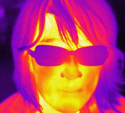
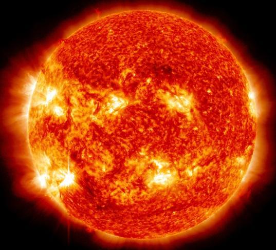
28 Thermal Imaging incandescent bulb 2700K campfire 1100K sun 5777K human 310K 28


29 Thermal Imaging Applications Thermal imaging is low cost and common Bad contacts get hot Relative temperature, emissivity unknown Electronic inspection Insulation problem Tumors are hot 29

30 Spectral Imaging More than RGB Precision measurement of spectral reflectance or absorbance (or self emission) Spectral emission of a flame Line scan spectral imaging camera measures moisture Determine chemical composition QC of colors make-up paints/pigments moisture content coating density and distribution combustion mix ratio determine emissivity crop stress melanoma 30


31 Spectral Imaging Color video camera VNIR-40 HPA camera VNIR-40 Chlorophyll/ camouflage detection 31
32 Questions Andrew Bodkin Bodkin Design & Engineering, LLC Newton, MA Andrew Bodkin has been a camera designer for the last 27 years. Designing camera systems for the military, biological, industrial and commercial users. He has built image intensified cameras, high speed cameras, polarization sensitive cameras, spectral analysis cameras, infrared cameras, moisture cameras, airborne cameras and worked on cameras for missile guidance and reconessence. He has worked for Textron, Loral, Ion Optics, and for the last 15 years has run his own engineering services business, building and designing cameras. He has over 7 patents for the equipment he has invented. The company now produces a proprietary design of high speed hyperspectral cameras that are used for chemical analysis for biological detection and quality control, as well as precision thermal analysis. 32
Optical design of a high resolution vision lens
 Optical design of a high resolution vision lens Paul Claassen, optical designer, paul.claassen@sioux.eu Marnix Tas, optical specialist, marnix.tas@sioux.eu Prof L.Beckmann, l.beckmann@hccnet.nl Summary:
LENSES. INEL 6088 Computer Vision
 LENSES INEL 6088 Computer Vision Digital camera A digital camera replaces film with a sensor array Each cell in the array is a Charge Coupled Device light-sensitive diode that converts photons to electrons
Variable microinspection system. system125
 Variable microinspection system system125 Variable micro-inspection system Characteristics Large fields, high NA The variable microinspection system mag.x system125 stands out from conventional LD inspection
Imaging Optics Fundamentals
 Imaging Optics Fundamentals Gregory Hollows Director, Machine Vision Solutions Edmund Optics Why Are We Here? Topics for Discussion Fundamental Parameters of your system Field of View Working Distance
Optical basics for machine vision systems. Lars Fermum Chief instructor STEMMER IMAGING GmbH
 Optical basics for machine vision systems Lars Fermum Chief instructor STEMMER IMAGING GmbH www.stemmer-imaging.de AN INTERNATIONAL CONCEPT STEMMER IMAGING customers in UK Germany France Switzerland Sweden
Advanced Camera and Image Sensor Technology. Steve Kinney Imaging Professional Camera Link Chairman
 Advanced Camera and Image Sensor Technology Steve Kinney Imaging Professional Camera Link Chairman Content Physical model of a camera Definition of various parameters for EMVA1288 EMVA1288 and image quality
Using molded chalcogenide glass technology to reduce cost in a compact wide-angle thermal imaging lens
 Using molded chalcogenide glass technology to reduce cost in a compact wide-angle thermal imaging lens George Curatu a, Brent Binkley a, David Tinch a, and Costin Curatu b a LightPath Technologies, 2603
Image Formation and Capture. Acknowledgment: some figures by B. Curless, E. Hecht, W.J. Smith, B.K.P. Horn, and A. Theuwissen
 Image Formation and Capture Acknowledgment: some figures by B. Curless, E. Hecht, W.J. Smith, B.K.P. Horn, and A. Theuwissen Image Formation and Capture Real world Optics Sensor Devices Sources of Error
Image Formation and Capture
 Figure credits: B. Curless, E. Hecht, W.J. Smith, B.K.P. Horn, A. Theuwissen, and J. Malik Image Formation and Capture COS 429: Computer Vision Image Formation and Capture Real world Optics Sensor Devices
or 640 x 480 pixels x 17 u Average Transmission 96% or 88% Depends on front surface coating (AR or DLC)
") ISP-TILK-18-1 LWIR 18mm F/1 Thermal Imaging Lens Kit White Paper PARAMETER VALUE NOTES Main Sub OPTICAL Focal Length / F# 18 / F1 Nominal values Detector (FPA) type / size Up to 388x 284 pixels x 25 u
ISP-TILK-18-1 LWIR 18mm F/1 Thermal Imaging Lens Kit White Paper PARAMETER VALUE NOTES Main Sub OPTICAL Focal Length / F# 18 / F1 Nominal values Detector (FPA) type / size Up to 388x 284 pixels x 25 u
Cameras As Computing Systems
 Cameras As Computing Systems Prof. Hank Dietz In Search Of Sensors University of Kentucky Electrical & Computer Engineering Things You Already Know The sensor is some kind of chip Most can't distinguish
CODE V Introductory Tutorial
 CODE V Introductory Tutorial Cheng-Fang Ho Lab.of RF-MW Photonics, Department of Physics, National Cheng-Kung University, Tainan, Taiwan 1-1 Tutorial Outline Introduction to CODE V Optical Design Process
VC 14/15 TP2 Image Formation
 VC 14/15 TP2 Image Formation Mestrado em Ciência de Computadores Mestrado Integrado em Engenharia de Redes e Sistemas Informáticos Miguel Tavares Coimbra Outline Computer Vision? The Human Visual System
Evaluating Commercial Scanners for Astronomical Images. The underlying technology of the scanners: Pixel sizes:
 Evaluating Commercial Scanners for Astronomical Images Robert J. Simcoe Associate Harvard College Observatory rjsimcoe@cfa.harvard.edu Introduction: Many organizations have expressed interest in using
CS559: Computer Graphics. Lecture 2: Image Formation in Eyes and Cameras Li Zhang Spring 2008
 CS559: Computer Graphics Lecture 2: Image Formation in Eyes and Cameras Li Zhang Spring 2008 Today Eyes Cameras Light Why can we see? Visible Light and Beyond Infrared, e.g. radio wave longer wavelength
Vision. The eye. Image formation. Eye defects & corrective lenses. Visual acuity. Colour vision. Lecture 3.5
 Lecture 3.5 Vision The eye Image formation Eye defects & corrective lenses Visual acuity Colour vision Vision http://www.wired.com/wiredscience/2009/04/schizoillusion/ Perception of light--- eye-brain
Using Optics to Optimize Your Machine Vision Application
 Expert Guide Using Optics to Optimize Your Machine Vision Application Introduction The lens is responsible for creating sufficient image quality to enable the vision system to extract the desired information
Advanced 3D Optical Profiler using Grasshopper3 USB3 Vision camera
 Advanced 3D Optical Profiler using Grasshopper3 USB3 Vision camera Figure 1. The Zeta-20 uses the Grasshopper3 and produces true color 3D optical images with multi mode optics technology 3D optical profiling
brief history of photography foveon X3 imager technology description
 brief history of photography foveon X3 imager technology description imaging technology 30,000 BC chauvet-pont-d arc pinhole camera principle first described by Aristotle fourth century B.C. oldest known
Compact camera module testing equipment with a conversion lens
 Compact camera module testing equipment with a conversion lens Jui-Wen Pan* 1 Institute of Photonic Systems, National Chiao Tung University, Tainan City 71150, Taiwan 2 Biomedical Electronics Translational
VC 11/12 T2 Image Formation
 VC 11/12 T2 Image Formation Mestrado em Ciência de Computadores Mestrado Integrado em Engenharia de Redes e Sistemas Informáticos Miguel Tavares Coimbra Outline Computer Vision? The Human Visual System
Virtual and Digital Cameras
 CS148: Introduction to Computer Graphics and Imaging Virtual and Digital Cameras Ansel Adams Topics Effect Cause Field of view Film size, focal length Perspective Lens, focal length Focus Dist. of lens
APPLICATIONS FOR TELECENTRIC LIGHTING
 APPLICATIONS FOR TELECENTRIC LIGHTING Telecentric lenses used in combination with telecentric lighting provide the most accurate results for measurement of object shapes and geometries. They make attributes
VC 16/17 TP2 Image Formation
 VC 16/17 TP2 Image Formation Mestrado em Ciência de Computadores Mestrado Integrado em Engenharia de Redes e Sistemas Informáticos Hélder Filipe Pinto de Oliveira Outline Computer Vision? The Human Visual
mm F2.6 6MP IR-Corrected. Sensor size
 1 1 inch and 1/1.2 inch image size spec. Sensor size 1-inch 1/1.2-inch 2/3-inch Image circle OK OK OK OK 1/1.8-inch OK 1/2-inch OK 1/2.5-inch 1 1-inch CMV4000 PYTHON5000 KAI-02150 KAI-2020 KAI-2093 KAI-4050
IMAGE SENSOR SOLUTIONS. KAC-96-1/5" Lens Kit. KODAK KAC-96-1/5" Lens Kit. for use with the KODAK CMOS Image Sensors. November 2004 Revision 2
 KODAK for use with the KODAK CMOS Image Sensors November 2004 Revision 2 1.1 Introduction Choosing the right lens is a critical aspect of designing an imaging system. Typically the trade off between image
General Imaging System
 General Imaging System Lecture Slides ME 4060 Machine Vision and Vision-based Control Chapter 5 Image Sensing and Acquisition By Dr. Debao Zhou 1 2 Light, Color, and Electromagnetic Spectrum Penetrate
Section 8. Objectives
 8-1 Section 8 Objectives Objectives Simple and Petval Objectives are lens element combinations used to image (usually) distant objects. To classify the objective, separated groups of lens elements are
ME 297 L4-2 Optical design flow Analysis
 ME 297 L4-2 Optical design flow Analysis Nayer Eradat Fall 2011 SJSU 1 Are we meeting the specs? First order requirements (after scaling the lens) Distortion Sharpness (diffraction MTF-will establish depth
BIG PIXELS VS. SMALL PIXELS THE OPTICAL BOTTLENECK. Gregory Hollows Edmund Optics
 BIG PIXELS VS. SMALL PIXELS THE OPTICAL BOTTLENECK Gregory Hollows Edmund Optics 1 IT ALL STARTS WITH THE SENSOR We have to begin with sensor technology to understand the road map Resolution will continue
Criteria for Optical Systems: Optical Path Difference How do we determine the quality of a lens system? Several criteria used in optical design
 Criteria for Optical Systems: Optical Path Difference How do we determine the quality of a lens system? Several criteria used in optical design Computer Aided Design Several CAD tools use Ray Tracing (see
digital film technology Resolution Matters what's in a pattern white paper standing the test of time
 digital film technology Resolution Matters what's in a pattern white paper standing the test of time standing the test of time An introduction >>> Film archives are of great historical importance as they
TRUESENSE SPARSE COLOR FILTER PATTERN OVERVIEW SEPTEMBER 30, 2013 APPLICATION NOTE REVISION 1.0
 TRUESENSE SPARSE COLOR FILTER PATTERN OVERVIEW SEPTEMBER 30, 2013 APPLICATION NOTE REVISION 1.0 TABLE OF CONTENTS Overview... 3 Color Filter Patterns... 3 Bayer CFA... 3 Sparse CFA... 3 Image Processing...
DIGITAL CAMERA SENSORS
 DIGITAL CAMERA SENSORS Bill Betts March 21, 2018 Camera Sensors The soul of a digital camera is its sensor - to determine image size, resolution, lowlight performance, depth of field, dynamic range, lenses
Chapters 1 & 2. Definitions and applications Conceptual basis of photogrammetric processing
 Chapters 1 & 2 Chapter 1: Photogrammetry Definitions and applications Conceptual basis of photogrammetric processing Transition from two-dimensional imagery to three-dimensional information Automation
CPSC 4040/6040 Computer Graphics Images. Joshua Levine
 CPSC 4040/6040 Computer Graphics Images Joshua Levine levinej@clemson.edu Lecture 04 Displays and Optics Sept. 1, 2015 Slide Credits: Kenny A. Hunt Don House Torsten Möller Hanspeter Pfister Agenda Open
Cardinal Points of an Optical System--and Other Basic Facts
 Cardinal Points of an Optical System--and Other Basic Facts The fundamental feature of any optical system is the aperture stop. Thus, the most fundamental optical system is the pinhole camera. The image
Building a Real Camera. Slides Credit: Svetlana Lazebnik
 Building a Real Camera Slides Credit: Svetlana Lazebnik Home-made pinhole camera Slide by A. Efros http://www.debevec.org/pinhole/ Shrinking the aperture Why not make the aperture as small as possible?
TSBB09 Image Sensors 2018-HT2. Image Formation Part 1
 TSBB09 Image Sensors 2018-HT2 Image Formation Part 1 Basic physics Electromagnetic radiation consists of electromagnetic waves With energy That propagate through space The waves consist of transversal
Digital Camera Sensors
 Digital Camera Sensors Agenda Basic Parts of a Digital Camera The Pixel Camera Sensor Pixels Camera Sensor Sizes Pixel Density CMOS vs. CCD Digital Signal Processors ISO, Noise & Light Sensor Comparison
ECEN 4606, UNDERGRADUATE OPTICS LAB
 ECEN 4606, UNDERGRADUATE OPTICS LAB Lab 2: Imaging 1 the Telescope Original Version: Prof. McLeod SUMMARY: In this lab you will become familiar with the use of one or more lenses to create images of distant
Reflectors vs. Refractors
 1 Telescope Types - Telescopes collect and concentrate light (which can then be magnified, dispersed as a spectrum, etc). - In the end it is the collecting area that counts. - There are two primary telescope
OCT Spectrometer Design Understanding roll-off to achieve the clearest images
 OCT Spectrometer Design Understanding roll-off to achieve the clearest images Building a high-performance spectrometer for OCT imaging requires a deep understanding of the finer points of both OCT theory
New foveated wide angle lens with high resolving power and without brightness loss in the periphery
 New foveated wide angle lens with high resolving power and without brightness loss in the periphery K. Wakamiya *a, T. Senga a, K. Isagi a, N. Yamamura a, Y. Ushio a and N. Kita b a Nikon Corp., 6-3,Nishi-ohi
Acquisition. Some slides from: Yung-Yu Chuang (DigiVfx) Jan Neumann, Pat Hanrahan, Alexei Efros
 Jan Neumann, Pat Hanrahan, Alexei Efros") Acquisition Some slides from: Yung-Yu Chuang (DigiVfx) Jan Neumann, Pat Hanrahan, Alexei Efros Image Acquisition Digital Camera Film Outline Pinhole camera Lens Lens aberrations Exposure Sensors Noise
Acquisition Some slides from: Yung-Yu Chuang (DigiVfx) Jan Neumann, Pat Hanrahan, Alexei Efros Image Acquisition Digital Camera Film Outline Pinhole camera Lens Lens aberrations Exposure Sensors Noise
COLOUR INSPECTION, INFRARED AND UV
 COLOUR INSPECTION, INFRARED AND UV TIPS, SPECIAL FEATURES, REQUIREMENTS LARS FERMUM, CHIEF INSTRUCTOR, STEMMER IMAGING THE PROPERTIES OF LIGHT Light is characterized by specifying the wavelength, amplitude
Optoliner NV. Calibration Standard for Sighting & Imaging Devices West San Bernardino Road West Covina, California 91790
 Calibration Standard for Sighting & Imaging Devices 2223 West San Bernardino Road West Covina, California 91790 Phone: (626) 962-5181 Fax: (626) 962-5188 www.davidsonoptronics.com sales@davidsonoptronics.com
Optical Components for Laser Applications. Günter Toesko - Laserseminar BLZ im Dezember
 Günter Toesko - Laserseminar BLZ im Dezember 2009 1 Aberrations An optical aberration is a distortion in the image formed by an optical system compared to the original. It can arise for a number of reasons
Opto Engineering S.r.l.
 TUTORIAL #1 Telecentric Lenses: basic information and working principles On line dimensional control is one of the most challenging and difficult applications of vision systems. On the other hand, besides
Announcement A total of 5 (five) late days are allowed for projects. Office hours
 late days are allowed for projects. Office hours") Announcement A total of 5 (five) late days are allowed for projects. Office hours Me: 3:50-4:50pm Thursday (or by appointment) Jake: 12:30-1:30PM Monday and Wednesday Image Formation Digital Camera Film
Announcement A total of 5 (five) late days are allowed for projects. Office hours Me: 3:50-4:50pm Thursday (or by appointment) Jake: 12:30-1:30PM Monday and Wednesday Image Formation Digital Camera Film
Building a Real Camera
 Building a Real Camera Home-made pinhole camera Slide by A. Efros http://www.debevec.org/pinhole/ Shrinking the aperture Why not make the aperture as small as possible? Less light gets through Diffraction
Hyperspectral goes to UAV and thermal
 Hyperspectral goes to UAV and thermal Timo Hyvärinen, Hannu Holma and Esko Herrala SPECIM, Spectral Imaging Ltd, Finland www.specim.fi Outline Roadmap to more compact, higher performance hyperspectral
PHY385H1F Introductory Optics. Practicals Session 7 Studying for Test 2
 PHY385H1F Introductory Optics Practicals Session 7 Studying for Test 2 Entrance Pupil & Exit Pupil A Cooke-triplet consists of three thin lenses in succession, and is often used in cameras. It was patented
Lecture 9. Lecture 9. t (min)
") Sensitivity of the Eye Lecture 9 The eye is capable of dark adaptation. This comes about by opening of the iris, as well as a change in rod cell photochemistry fovea only least perceptible brightness 10
Sensitivity of the Eye Lecture 9 The eye is capable of dark adaptation. This comes about by opening of the iris, as well as a change in rod cell photochemistry fovea only least perceptible brightness 10
Parallel Mode Confocal System for Wafer Bump Inspection
 Parallel Mode Confocal System for Wafer Bump Inspection ECEN5616 Class Project 1 Gao Wenliang wen-liang_gao@agilent.com 1. Introduction In this paper, A parallel-mode High-speed Line-scanning confocal
Chapters 1-3. Chapter 1: Introduction and applications of photogrammetry Chapter 2: Electro-magnetic radiation. Chapter 3: Basic optics
 Chapters 1-3 Chapter 1: Introduction and applications of photogrammetry Chapter 2: Electro-magnetic radiation Radiation sources Classification of remote sensing systems (passive & active) Electromagnetic
Projection. Readings. Szeliski 2.1. Wednesday, October 23, 13
 Projection Readings Szeliski 2.1 Projection Readings Szeliski 2.1 Müller-Lyer Illusion by Pravin Bhat Müller-Lyer Illusion by Pravin Bhat http://www.michaelbach.de/ot/sze_muelue/index.html Müller-Lyer
Fundamental Paraxial Equation for Thin Lenses
 THIN LENSES Fundamental Paraxial Equation for Thin Lenses A thin lens is one for which thickness is "negligibly" small and may be ignored. Thin lenses are the most important optical entity in ophthalmic
Lecture 22: Cameras & Lenses III. Computer Graphics and Imaging UC Berkeley CS184/284A, Spring 2017
 Lecture 22: Cameras & Lenses III Computer Graphics and Imaging UC Berkeley, Spring 2017 F-Number For Lens vs. Photo A lens s F-Number is the maximum for that lens E.g. 50 mm F/1.4 is a high-quality telephoto
Chapters 1-3. Chapter 1: Introduction and applications of photogrammetry Chapter 2: Electro-magnetic radiation. Chapter 3: Basic optics
 Chapters 1-3 Chapter 1: Introduction and applications of photogrammetry Chapter 2: Electro-magnetic radiation Radiation sources Classification of remote sensing systems (passive & active) Electromagnetic
An Indian Journal FULL PAPER. Trade Science Inc. Parameters design of optical system in transmitive star simulator ABSTRACT KEYWORDS
 [Type text] [Type text] [Type text] ISSN : 0974-7435 Volume 10 Issue 23 BioTechnology 2014 An Indian Journal FULL PAPER BTAIJ, 10(23), 2014 [14257-14264] Parameters design of optical system in transmitive
EE-527: MicroFabrication
 EE-57: MicroFabrication Exposure and Imaging Photons white light Hg arc lamp filtered Hg arc lamp excimer laser x-rays from synchrotron Electrons Ions Exposure Sources focused electron beam direct write
Adaptive Optics for LIGO
 Adaptive Optics for LIGO Justin Mansell Ginzton Laboratory LIGO-G990022-39-M Motivation Wavefront Sensor Outline Characterization Enhancements Modeling Projections Adaptive Optics Results Effects of Thermal
Angle of View & Image Resolution
 White Paper HD Cameras 4500/4900 Series Angle of View & Image Resolution English Rev. 1.0.1 / 2012-10-04 1 Abstract Dallmeier HD cameras of the 4500 / 4900 series provide high-quality images at resolutions
Laser Speckle Reducer LSR-3000 Series
 Datasheet: LSR-3000 Series Update: 06.08.2012 Copyright 2012 Optotune Laser Speckle Reducer LSR-3000 Series Speckle noise from a laser-based system is reduced by dynamically diffusing the laser beam. A
OPTICAL SYSTEMS OBJECTIVES
 101 L7 OPTICAL SYSTEMS OBJECTIVES Aims Your aim here should be to acquire a working knowledge of the basic components of optical systems and understand their purpose, function and limitations in terms
Ultralight Weight Optical Systems using Nano-Layered Synthesized Materials
 Ultralight Weight Optical Systems using Nano-Layered Synthesized Materials Natalie Clark, PhD NASA Langley Research Center and James Breckinridge University of Arizona, College of Optical Sciences Overview
 Telecentric Imaging Object space telecentricity stop source: edmund optics The 5 classical Seidel Aberrations First order aberrations Spherical Aberration (~r 4 ) Origin: different focal lengths for different
Lecture 4: Geometrical Optics 2. Optical Systems. Images and Pupils. Rays. Wavefronts. Aberrations. Outline
 Lecture 4: Geometrical Optics 2 Outline 1 Optical Systems 2 Images and Pupils 3 Rays 4 Wavefronts 5 Aberrations Christoph U. Keller, Leiden University, keller@strw.leidenuniv.nl Lecture 4: Geometrical
Geometry of Aerial Photographs
 Geometry of Aerial Photographs Aerial Cameras Aerial cameras must be (details in lectures): Geometrically stable Have fast and efficient shutters Have high geometric and optical quality lenses They can
OPAL Optical Profiling of the Atmospheric Limb
 OPAL Optical Profiling of the Atmospheric Limb Alan Marchant Chad Fish Erik Stromberg Charles Swenson Jim Peterson OPAL STEADE Mission Storm Time Energy & Dynamics Explorers NASA Mission of Opportunity
Basic principles of photography. David Capel 346B IST
 Basic principles of photography David Capel 346B IST Latin Camera Obscura = Dark Room Light passing through a small hole produces an inverted image on the opposite wall Safely observing the solar eclipse
RESOLUTION PERFORMANCE IMPROVEMENTS IN STARING IMAGING SYSTEMS USING MICRO-SCANNING AND A RETICULATED, SELECTABLE FILL FACTOR InSb FPA.
 Approved for public release; distribution is unlimited RESOLUTION PERFORMANCE IMPROVEMENTS IN STARING IMAGING SYSTEMS USING MICRO-SCANNING AND A RETICULATED, SELECTABLE FILL FACTOR InSb FPA February 1999
Basler Accessories. Technical Specification BASLER LENS C M. Order Number
 Basler Accessories Technical Specification BASLER LENS C23-526-2M Order Number 22183 Document Number: DG1916 Version: 1 Language: (English) Release Date: 17 January 218 Contacting Basler Support Worldwide
Basler Accessories. Technical Specification BASLER LENS C M. Order Number
 Basler Accessories Technical Specification BASLER LENS C23-1616-2M Order Number 2200000180 Document Number: DG001913 Version: 01 Language: 000 (English) Release Date: 17 January 2018 Contacting Basler
Two strategies for realistic rendering capture real world data synthesize from bottom up
 Recap from Wednesday Two strategies for realistic rendering capture real world data synthesize from bottom up Both have existed for 500 years. Both are successful. Attempts to take the best of both world
ECEN. Spectroscopy. Lab 8. copy. constituents HOMEWORK PR. Figure. 1. Layout of. of the
 ECEN 4606 Lab 8 Spectroscopy SUMMARY: ROBLEM 1: Pedrotti 3 12-10. In this lab, you will design, build and test an optical spectrum analyzer and use it for both absorption and emission spectroscopy. The
Using Machine Vision Cameras for Solar Imaging. Dr Stuart Green
 Using Machine Vision Cameras for Solar Imaging Dr Stuart Green Hubble Ultra-deep Field Image Estimated 100 billion galaxies in the observable universe Estimated 200-400 billion stars in our own galaxy
Camera Selection Criteria. Richard Crisp May 25, 2011
 Camera Selection Criteria Richard Crisp rdcrisp@earthlink.net www.narrowbandimaging.com May 25, 2011 Size size considerations Key issues are matching the pixel size to the expected spot size from the optical
Projection. Projection. Image formation. Müller-Lyer Illusion. Readings. Readings. Let s design a camera. Szeliski 2.1. Szeliski 2.
 Projection Projection Readings Szeliski 2.1 Readings Szeliski 2.1 Müller-Lyer Illusion Image formation object film by Pravin Bhat http://www.michaelbach.de/ot/sze_muelue/index.html Let s design a camera
Optical and mechanical parameters. 100 mm N. of elements 20.5 mm Dimensions 11.7 degrees Weight F/N = 4 (fixed) N.A.
 N.A.") OB SWIR 100 LENS OB-SWIR100/4 P/N C0416 General Description This family of high resolution SWIR lenses image from 0.9 2.3 µmm making them especially well-suited for PCB inspection, special laser applications,
OB SWIR 100 LENS OB-SWIR100/4 P/N C0416 General Description This family of high resolution SWIR lenses image from 0.9 2.3 µmm making them especially well-suited for PCB inspection, special laser applications,
LEOK-3 Optics Experiment kit
 LEOK-3 Optics Experiment kit Physical optics, geometrical optics and fourier optics Covering 26 experiments Comprehensive documents Include experiment setups, principles and procedures Cost effective solution
Cameras. CSE 455, Winter 2010 January 25, 2010
 Cameras CSE 455, Winter 2010 January 25, 2010 Announcements New Lecturer! Neel Joshi, Ph.D. Post-Doctoral Researcher Microsoft Research neel@cs Project 1b (seam carving) was due on Friday the 22 nd Project
Including 12µ Compatible Lenses
 SupIR Catalog 2015-16 Including 12µ Compatible Lenses Uncooled 3-5µ Uncooled 8-12µ Zoom- Uncooled Radiometric Athermalized Cooled Zoom- Cooled 1About Ophir OPHIR - A NEWPORT COMPANY Ophir and its affiliates
Chapter 23 Study Questions Name: Class:
 Chapter 23 Study Questions Name: Class: Multiple Choice Identify the letter of the choice that best completes the statement or answers the question. 1. When you look at yourself in a plane mirror, you
Image Formation. Light from distant things. Geometrical optics. Pinhole camera. Chapter 36
 Light from distant things Chapter 36 We learn about a distant thing from the light it generates or redirects. The lenses in our eyes create images of objects our brains can process. This chapter concerns
ECEN 4606, UNDERGRADUATE OPTICS LAB
 ECEN 4606, UNDERGRADUATE OPTICS LAB Lab 3: Imaging 2 the Microscope Original Version: Professor McLeod SUMMARY: In this lab you will become familiar with the use of one or more lenses to create highly
Digital Camera Technologies for Scientific Bio-Imaging. Part 2: Sampling and Signal
 Digital Camera Technologies for Scientific Bio-Imaging. Part 2: Sampling and Signal Yashvinder Sabharwal, 1 James Joubert 2 and Deepak Sharma 2 1. Solexis Advisors LLC, Austin, TX, USA 2. Photometrics
Introduction to Optical Modeling. Friedrich-Schiller-University Jena Institute of Applied Physics. Lecturer: Prof. U.D. Zeitner
 Introduction to Optical Modeling Friedrich-Schiller-University Jena Institute of Applied Physics Lecturer: Prof. U.D. Zeitner The Nature of Light Fundamental Question: What is Light? Newton Huygens / Maxwell
What will be on the midterm?
 What will be on the midterm? CS 178, Spring 2014 Marc Levoy Computer Science Department Stanford University General information 2 Monday, 7-9pm, Cubberly Auditorium (School of Edu) closed book, no notes
Human Retina. Sharp Spot: Fovea Blind Spot: Optic Nerve
 I am Watching YOU!! Human Retina Sharp Spot: Fovea Blind Spot: Optic Nerve Human Vision Optical Antennae: Rods & Cones Rods: Intensity Cones: Color Energy of Light 6 10 ev 10 ev 4 1 2eV 40eV KeV MeV Energy
Will contain image distance after raytrace Will contain image height after raytrace
 Name: LASR 51 Final Exam May 29, 2002 Answer all questions. Module numbers are for guidance, some material is from class handouts. Exam ends at 8:20 pm. Ynu Raytracing The first questions refer to the
Applications of Optics
 Nicholas J. Giordano www.cengage.com/physics/giordano Chapter 26 Applications of Optics Marilyn Akins, PhD Broome Community College Applications of Optics Many devices are based on the principles of optics
PHYSICS. Chapter 35 Lecture FOR SCIENTISTS AND ENGINEERS A STRATEGIC APPROACH 4/E RANDALL D. KNIGHT
 PHYSICS FOR SCIENTISTS AND ENGINEERS A STRATEGIC APPROACH 4/E Chapter 35 Lecture RANDALL D. KNIGHT Chapter 35 Optical Instruments IN THIS CHAPTER, you will learn about some common optical instruments and
Laser Telemetric System (Metrology)
") Laser Telemetric System (Metrology) Laser telemetric system is a non-contact gauge that measures with a collimated laser beam (Refer Fig. 10.26). It measure at the rate of 150 scans per second. It basically
Laser Telemetric System (Metrology) Laser telemetric system is a non-contact gauge that measures with a collimated laser beam (Refer Fig. 10.26). It measure at the rate of 150 scans per second. It basically
Warren J. Smith Chief Scientist, Consultant Rockwell Collins Optronics Carlsbad, California
 Modern Optical Engineering The Design of Optical Systems Warren J. Smith Chief Scientist, Consultant Rockwell Collins Optronics Carlsbad, California Fourth Edition Me Graw Hill New York Chicago San Francisco
Imaging Instruments (part I)
") Imaging Instruments (part I) Principal Planes and Focal Lengths (Effective, Back, Front) Multi-element systems Pupils & Windows; Apertures & Stops the Numerical Aperture and f/# Single-Lens Camera Human
Imaging Instruments (part I) Principal Planes and Focal Lengths (Effective, Back, Front) Multi-element systems Pupils & Windows; Apertures & Stops the Numerical Aperture and f/# Single-Lens Camera Human
Lecture 2: Geometrical Optics. Geometrical Approximation. Lenses. Mirrors. Optical Systems. Images and Pupils. Aberrations.
 Lecture 2: Geometrical Optics Outline 1 Geometrical Approximation 2 Lenses 3 Mirrors 4 Optical Systems 5 Images and Pupils 6 Aberrations Christoph U. Keller, Leiden Observatory, keller@strw.leidenuniv.nl
Lenses, exposure, and (de)focus
focus") Lenses, exposure, and (de)focus http://graphics.cs.cmu.edu/courses/15-463 15-463, 15-663, 15-862 Computational Photography Fall 2017, Lecture 15 Course announcements Homework 4 is out. - Due October 26
Lenses, exposure, and (de)focus http://graphics.cs.cmu.edu/courses/15-463 15-463, 15-663, 15-862 Computational Photography Fall 2017, Lecture 15 Course announcements Homework 4 is out. - Due October 26
EE119 Introduction to Optical Engineering Spring 2003 Final Exam. Name:
 EE119 Introduction to Optical Engineering Spring 2003 Final Exam Name: SID: CLOSED BOOK. THREE 8 1/2 X 11 SHEETS OF NOTES, AND SCIENTIFIC POCKET CALCULATOR PERMITTED. TIME ALLOTTED: 180 MINUTES Fundamental