Variable microinspection system. system125
|
|
|
- Prudence Hampton
- 6 years ago
- Views:
Transcription
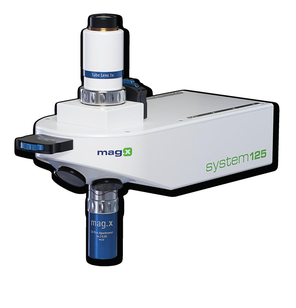

1 Variable microinspection system system125


2 Variable micro-inspection system Characteristics Large fields, high NA The variable microinspection system mag.x system125 stands out from conventional LD inspection systems by virtue of its low overall magnifications that transmit large object fields in high quality. This is achieved through numerical aperture (NA) values far higher than those of other systems. High optical quality is not only ensured on the optical axis, but also is maintained over the entire sensor format. With the tube lens 2.25x, sensor formats up to 56mm are supported. Long distance lenses Thanks to long working distances and correction of the lenses without cover glasses, this system can be universally employed in technical inspection applications. The parfocal distance of the lenses is 125mm. Object space telecentricity Exact object space telecentricity is precisely maintained, preventing flawed measurement results resulting from deep objects or because a variation in object position.
 for epi-brightfield illumination.")
 can be appropriately adjusted for individual inspection tasks.")
.")
3 Coupled illumination The high quality of the optical image can only be fully exploited if the object illumination is optimally adjusted. This is why mag.x system125 has a built-in coupled illumination beam path (vertical illuminator) for epi-brightfield illumination. The illumination system operates on the Kohler principle, with adjustable aperture and field stops. Thus the illumination and coherence parameters of the image (relationship of illumination and imaging aperture) can be appropriately adjusted for individual inspection tasks. Fur thermore, the pupil position can be adjusted to the particular lens used, ensuring the optimum telecentric illumination for any lens. Chromatic correction The optics are highly chromatically corrected in the spectral range of nm (up to nm, depending on device configurations). The contrast is maintained over the entire spectrum; no re-focusing is required. Modular system The system can be modular modified for adaptation to the customer s exact requirements. Changing individual components is an highly timesaving alternative to developing a new system.
4 Variable micro-inspection system Schematic drawing of the system Tube system Polarizing filter, rotatable Polarizing filter, rotatable Filter Turret Light guide adapter Illumination unit Objective Specifications Magn. / NA Objective Plan Apochromat Tube Lens System 0.5x 1x 2.25x f tub = 125mm f tub = 250mm f tub = 563mm 2y = 12.5mm 2y = 25mm 2y = 56.25mm WD f obj δ R 0 2y R 0 2y R 0 2y R 0 mm mm µm lp/mm M mm NA lp/mm M mm NA lp/mm M mm NA lp/mm 2x / ± x / ± x / ± x / ± NA: Object space Numerical Aperture NA : Image space Numerical Aperture WD: Working distance f obj : Focal length of objective lens f tub : Focal length of tube lens system δ: Diffraction limited depth of focus at 546nm, δ = ±n λ /(2 NA 2 ) R 0 : Cut-off frequency in object space at 546nm, R 0 = (2 NA) / λ R 0 : Cut-off frequency in image space at 546nm 2y: Field of view 2y : Image field (maximum detector diagonal) M: Total system magnification in preparation
5 Performance The following graph displays the optical performance of the mag.x system125 microinspection system, showing the polychromatic MTF versus field height. Values for image and object heights are given under the horizontal axis. Note that the high contrast values close to the diffraction limit are maintained over the entire field! MTF R=100 lp/mm R =9 lp/mm R=300 lp/mm R =27 lp/mm R=500 lp/mm R =44 lp/mm y= y = Feldhöhe Field height Polychromatic MTF vs. field height LD Plan Apo 5x/0.2 + TL2.25x 2y=5 mm, 2y =56.3 mm Applications The usage of high resolution large-format detectors speed up the inspection process. Extremely sensitive line scan sensors, up to 56mm long, enable manufacturers to inspect large areas at high speed, significantly increasing thoughput. Optimally adjusted Kohler illumination highlights even the smallest defects. The excellent optical performance is sustained all the way to the image edge, so that the complete sensor length can be utilised. A telecentric object space beam path means that the optics can also be used for measurement tasks. Careful optimisation of the lenses for the greatest possible working distances affords maximum flexibility in daily production monitoring. With this system, small detectors with sensor diagonals of 2/3 inch and resolutions of over 10 megapixels can be exploited over the entire sensor range. Pixel sizes of around 1.7μm are no problem. Ideal areas of application: Semiconductor industry Flat panel inspection OLED inspection Packaging Photovoltaic and solar panel inspection Universities, laboratories Technical microscopy
6 Discover the Q! Discover the capabilities, knowledge, equipment and technology of Qioptiq Photonics for Innovation For technical information contact: Qioptiq Photonics GmbH & Co.KG Jan Förster Königsallee Göttingen Direct: +49 (0)5 51 / Main: +49 (0)5 51 / Fax: +49 (0)5 51 / jan.foerster@qioptiq.de
Xenon-Zirconia 3.3/92
 This lens with.2x magnification is optimized for the use with 12k (62.5 mm) line scan sensors with 5 µm pixel, but can also be used with 16k (82 mm) lines. It is broadband coated and can be used in the
Xenon-Diamond 2.9/106 With beam splitter
 Xenon-Diamond 2.9/16 This high resolution 2.6x line scan lens with beam splitter is optimized for the use with 12k (62.5 mm) line scan sensors with 5 µm pixel, but can also be used with 16k / 5 µm (82
Optical basics for machine vision systems. Lars Fermum Chief instructor STEMMER IMAGING GmbH
 Optical basics for machine vision systems Lars Fermum Chief instructor STEMMER IMAGING GmbH www.stemmer-imaging.de AN INTERNATIONAL CONCEPT STEMMER IMAGING customers in UK Germany France Switzerland Sweden
TECHSPEC COMPACT FIXED FOCAL LENGTH LENS
 Designed for use in machine vision applications, our TECHSPEC Compact Fixed Focal Length Lenses are ideal for use in factory automation, inspection or qualification. These machine vision lenses have been
Optical design of a high resolution vision lens
 Optical design of a high resolution vision lens Paul Claassen, optical designer, paul.claassen@sioux.eu Marnix Tas, optical specialist, marnix.tas@sioux.eu Prof L.Beckmann, l.beckmann@hccnet.nl Summary:
Imaging Optics Fundamentals
 Imaging Optics Fundamentals Gregory Hollows Director, Machine Vision Solutions Edmund Optics Why Are We Here? Topics for Discussion Fundamental Parameters of your system Field of View Working Distance
Basler Accessories. Technical Specification BASLER LENS C M. Order Number
 Basler Accessories Technical Specification BASLER LENS C23-526-2M Order Number 22183 Document Number: DG1916 Version: 1 Language: (English) Release Date: 17 January 218 Contacting Basler Support Worldwide
Basler Accessories. Technical Specification BASLER LENS C M. Order Number
 Basler Accessories Technical Specification BASLER LENS C23-1616-2M Order Number 2200000180 Document Number: DG001913 Version: 01 Language: 000 (English) Release Date: 17 January 2018 Contacting Basler
For high resolution, large-sized line sensor cameras. Recommendable line sensor cameras - 5.2μm x 12K / 7μm x 8K
 Nikon Rayfact Series Features For high resolution, large-sized line sensor cameras. Recommendable line sensor cameras - 5.2μm x 12K / 7μm x 8K Guarantee high resolution and uniformity from the center to
INFLUENCE OF VARIABLE APERTURE STOP
 INFLUENCE OF VARIABLE APERTURE STOP IN TELECENTRIC IMAGING LENSES SILL OPTICS GMBH CO. KG TECHNOLOGY FORUM MACHINE VISION 2015/16 Konrad Hentschel, Dipl-Phys. Andreas Platz, M.Sc. Project Management CONTENT
Optical Components for Laser Applications. Günter Toesko - Laserseminar BLZ im Dezember
 Günter Toesko - Laserseminar BLZ im Dezember 2009 1 Aberrations An optical aberration is a distortion in the image formed by an optical system compared to the original. It can arise for a number of reasons
Imaging Introduction. September 24, 2010
 Imaging Introduction September 24, 2010 What is a microscope? Merriam-Webster: an optical instrument consisting of a lens or combination of lenses for making enlarged images of minute objects; especially:
ABOUT RESOLUTION. pco.knowledge base
 The resolution of an image sensor describes the total number of pixel which can be used to detect an image. From the standpoint of the image sensor it is sufficient to count the number and describe it
Microscopy: Fundamental Principles and Practical Approaches
 Microscopy: Fundamental Principles and Practical Approaches Simon Atkinson Online Resource: http://micro.magnet.fsu.edu/primer/index.html Book: Murphy, D.B. Fundamentals of Light Microscopy and Electronic
Macro Varon 4.5/85. Key features. Applications. Web and surface inspections
 The Macro Varon lens has been designed for high resolution 12k line scan cameras with 3.5 µm pixel pitch. They are optimized for an optical magnification range of.5x to 2.x. CAS-lens technology produces
The Compound Microscope. Brightfield: Köhler Illumination
 Outline History of Microscopy The Magnifying Glass The Compound Microscope Brightfield: Köhler Illumination Microscopy µικροσ (mikros): small σκοπειν (skopein): to observe History of Microscopy Well :
How to Choose a Machine Vision Camera for Your Application.
 Vision Systems Design Webinar 9 September 2015 How to Choose a Machine Vision Camera for Your Application. Andrew Bodkin Bodkin Design & Engineering, LLC Newton, MA 02464 617-795-1968 wab@bodkindesign.com
CCAM Microscope Objectives
 CCAM Microscope Objectives Things to consider when selecting an objective Magnification Numerical Aperture (NA) resolving power and light intensity of the objective Working Distance distance between the
Systematic Workflow via Intuitive GUI. Easy operation accomplishes your goals faster than ever.
 Systematic Workflow via Intuitive GUI Easy operation accomplishes your goals faster than ever. 16 With the LEXT OLS4100, observation or measurement begins immediately once the sample is placed on the stage.
Optical and mechanical parameters. 100 mm N. of elements 20.5 mm Dimensions 11.7 degrees Weight F/N = 4 (fixed) N.A.
 N.A.") OB SWIR 100 LENS OB-SWIR100/4 P/N C0416 General Description This family of high resolution SWIR lenses image from 0.9 2.3 µmm making them especially well-suited for PCB inspection, special laser applications,
OB SWIR 100 LENS OB-SWIR100/4 P/N C0416 General Description This family of high resolution SWIR lenses image from 0.9 2.3 µmm making them especially well-suited for PCB inspection, special laser applications,
BIG PIXELS VS. SMALL PIXELS THE OPTICAL BOTTLENECK. Gregory Hollows Edmund Optics
 BIG PIXELS VS. SMALL PIXELS THE OPTICAL BOTTLENECK Gregory Hollows Edmund Optics 1 IT ALL STARTS WITH THE SENSOR We have to begin with sensor technology to understand the road map Resolution will continue
Introduction to Light Microscopy. (Image: T. Wittman, Scripps)
") Introduction to Light Microscopy (Image: T. Wittman, Scripps) The Light Microscope Four centuries of history Vibrant current development One of the most widely used research tools A. Khodjakov et al. Major
Introduction to Light Microscopy (Image: T. Wittman, Scripps) The Light Microscope Four centuries of history Vibrant current development One of the most widely used research tools A. Khodjakov et al. Major
attocfm I for Surface Quality Inspection NANOSCOPY APPLICATION NOTE M01 RELATED PRODUCTS G
 APPLICATION NOTE M01 attocfm I for Surface Quality Inspection Confocal microscopes work by scanning a tiny light spot on a sample and by measuring the scattered light in the illuminated volume. First,
2/4/15. Brightfield Microscopy! It s all about Magnification..! or is it?!
 Brightfield Microscopy It s all about Magnification.. or is it? 1 What actually does go into chosing a microscope Choice depends on what you need the microscope to do. Do you want to magnify stained specimens?
LEICA Summarit-S 70 mm ASPH. f/2.5 / CS
 Technical Data. Illustration 1:2 Technical Data Order no. 1155 (CS: 1151) Image angle (diagonal, horizontal, vertical) approx. 42 / 35 / 24, corresponds to approx. 56 focal length in 35 format Optical
Properties of optical instruments. Visual optical systems part 2: focal visual instruments (microscope type)
") Properties of optical instruments Visual optical systems part 2: focal visual instruments (microscope type) Examples of focal visual instruments magnifying glass Eyepieces Measuring microscopes from the
Properties of optical instruments Visual optical systems part 2: focal visual instruments (microscope type) Examples of focal visual instruments magnifying glass Eyepieces Measuring microscopes from the
Opti 415/515. Introduction to Optical Systems. Copyright 2009, William P. Kuhn
 Opti 415/515 Introduction to Optical Systems 1 Optical Systems Manipulate light to form an image on a detector. Point source microscope Hubble telescope (NASA) 2 Fundamental System Requirements Application
OPTICAL PRINCIPLES OF MICROSCOPY. Interuniversity Course 28 December 2003 Aryeh M. Weiss Bar Ilan University
 OPTICAL PRINCIPLES OF MICROSCOPY Interuniversity Course 28 December 2003 Aryeh M. Weiss Bar Ilan University FOREWORD This slide set was originally presented at the ISM Workshop on Theoretical and Experimental
Telecentric lenses.
 Telecentric lenses 2014 Bi-Telecentric lenses Titolo Index Descrizione Telecentric lenses Opto Engineering Telecentric lenses represent our core business: these products benefit from a decade-long effort
Transmission Electron Microscopy 9. The Instrument. Outline
 Transmission Electron Microscopy 9. The Instrument EMA 6518 Spring 2009 02/25/09 Outline The Illumination System The Objective Lens and Stage Forming Diffraction Patterns and Images Alignment and Stigmation
Speed and Image Brightness uniformity of telecentric lenses
 Specialist Article Published by: elektronikpraxis.de Issue: 11 / 2013 Speed and Image Brightness uniformity of telecentric lenses Author: Dr.-Ing. Claudia Brückner, Optics Developer, Vision & Control GmbH
Using Optics to Optimize Your Machine Vision Application
 Expert Guide Using Optics to Optimize Your Machine Vision Application Introduction The lens is responsible for creating sufficient image quality to enable the vision system to extract the desired information
IMAGE SENSOR SOLUTIONS. KAC-96-1/5" Lens Kit. KODAK KAC-96-1/5" Lens Kit. for use with the KODAK CMOS Image Sensors. November 2004 Revision 2
 KODAK for use with the KODAK CMOS Image Sensors November 2004 Revision 2 1.1 Introduction Choosing the right lens is a critical aspect of designing an imaging system. Typically the trade off between image
Criteria for Optical Systems: Optical Path Difference How do we determine the quality of a lens system? Several criteria used in optical design
 Criteria for Optical Systems: Optical Path Difference How do we determine the quality of a lens system? Several criteria used in optical design Computer Aided Design Several CAD tools use Ray Tracing (see
Optical Components - Scanning Lenses
 Optical Components Scanning Lenses Scanning Lenses (Ftheta) Product Information Figure 1: Scanning Lenses A scanning (Ftheta) lens supplies an image in accordance with the socalled Ftheta condition (y
APPLICATIONS FOR TELECENTRIC LIGHTING
 APPLICATIONS FOR TELECENTRIC LIGHTING Telecentric lenses used in combination with telecentric lighting provide the most accurate results for measurement of object shapes and geometries. They make attributes
Shaping light in microscopy:
 Shaping light in microscopy: Adaptive optical methods and nonconventional beam shapes for enhanced imaging Martí Duocastella planet detector detector sample sample Aberrated wavefront Beamsplitter Adaptive
microscopy A great online resource Molecular Expressions, a Microscope Primer Partha Roy
 Fundamentals of optical microscopy A great online resource Molecular Expressions, a Microscope Primer http://micro.magnet.fsu.edu/primer/index.html Partha Roy 1 Why microscopy Topics Functions of a microscope
EE119 Introduction to Optical Engineering Spring 2003 Final Exam. Name:
 EE119 Introduction to Optical Engineering Spring 2003 Final Exam Name: SID: CLOSED BOOK. THREE 8 1/2 X 11 SHEETS OF NOTES, AND SCIENTIFIC POCKET CALCULATOR PERMITTED. TIME ALLOTTED: 180 MINUTES Fundamental
nanovea.com PROFILOMETERS 3D Non Contact Metrology
 PROFILOMETERS 3D Non Contact Metrology nanovea.com PROFILOMETER INTRO Nanovea 3D Non-Contact Profilometers are designed with leading edge optical pens using superior white light axial chromatism. Nano
Calibration Report. Short Version. Vexcel Imaging GmbH, A-8010 Graz, Austria
 Calibration Report Short Version Camera: Manufacturer: UltraCam D, S/N UCD-SU-2-0039 Vexcel Imaging GmbH, A-8010 Graz, Austria Date of Calibration: Mar-14-2011 Date of Report: Mar-17-2011 Camera Revision:
BASICS IN BIOIMAGING AND OPTICS PLATFORM EPFL SV PTBIOP LIGHT MICROSCOPY
 BASICS IN LIGHT MICROSCOPY OVERVIEW 1. Motivation 2. Basic in optics 3. How microscope works 4. Illumination and resolution 5. Microscope optics 6. Contrasting methods -2- MOTIVATION Why do we need microscopy?
Nature Protocols: doi: /nprot Supplementary Figure 1. Schematic diagram of Kőhler illumination.
 Supplementary Figure 1 Schematic diagram of Kőhler illumination. The green beam path represents the excitation path and the red represents the emission path. Supplementary Figure 2 Microscope base components
Scanning Electron Microscopy SEM. Warren Straszheim, PhD MARL, 23 Town Engineering
 Scanning Electron Microscopy SEM Warren Straszheim, PhD MARL, 23 Town Engineering wesaia@iastate.edu 515-294-8187 How it works Create a focused electron beam Accelerate it Scan it across the sample Map
Ryf AG Bettlachstrasse Grenchen tel fax Industrial Microscopes
 Ryf AG Bettlachstrasse 2 2540 Grenchen tel 032 654 21 00 fax 032 654 21 09 www.ryfag.ch Industrial Microscopes The ECLIPSE microscope body has been modularized to meet industrial microscope applications
Physics 431 Final Exam Examples (3:00-5:00 pm 12/16/2009) TIME ALLOTTED: 120 MINUTES Name: Signature:
 TIME ALLOTTED: 120 MINUTES Name: Signature:") Physics 431 Final Exam Examples (3:00-5:00 pm 12/16/2009) TIME ALLOTTED: 120 MINUTES Name: PID: Signature: CLOSED BOOK. TWO 8 1/2 X 11 SHEET OF NOTES (double sided is allowed), AND SCIENTIFIC POCKET CALCULATOR
Physics 431 Final Exam Examples (3:00-5:00 pm 12/16/2009) TIME ALLOTTED: 120 MINUTES Name: PID: Signature: CLOSED BOOK. TWO 8 1/2 X 11 SHEET OF NOTES (double sided is allowed), AND SCIENTIFIC POCKET CALCULATOR
Biology 29 Cell Structure and Function Spring, 2009 Springer LABORATORY 1: THE LIGHT MICROSCOPE
 Biology 29 Cell Structure and Function Spring, 2009 Springer LABORATORY 1: THE LIGHT MICROSCOPE Prior to lab: 1) Read these instructions (p 1-6) 2) Go through the online tutorial, the microscopy pre-lab
Lecture Notes 10 Image Sensor Optics. Imaging optics. Pixel optics. Microlens
 Lecture Notes 10 Image Sensor Optics Imaging optics Space-invariant model Space-varying model Pixel optics Transmission Vignetting Microlens EE 392B: Image Sensor Optics 10-1 Image Sensor Optics Microlens
Filter & Spectrometer Electron Optics
 Filter & Spectrometer Electron Optics Parameters Affecting Practical Performance Daniel Moonen & Harold A. Brink Did Something Go Wrong? 30 20 10 0 500 600 700 800 900 1000 1100 ev 1 Content The Prism
Using molded chalcogenide glass technology to reduce cost in a compact wide-angle thermal imaging lens
 Using molded chalcogenide glass technology to reduce cost in a compact wide-angle thermal imaging lens George Curatu a, Brent Binkley a, David Tinch a, and Costin Curatu b a LightPath Technologies, 2603
Development of a new multi-wavelength confocal surface profilometer for in-situ automatic optical inspection (AOI)
") Development of a new multi-wavelength confocal surface profilometer for in-situ automatic optical inspection (AOI) Liang-Chia Chen 1#, Chao-Nan Chen 1 and Yi-Wei Chang 1 1. Institute of Automation Technology,
Development of a new multi-wavelength confocal surface profilometer for in-situ automatic optical inspection (AOI) Liang-Chia Chen 1#, Chao-Nan Chen 1 and Yi-Wei Chang 1 1. Institute of Automation Technology,
Basics of Light Microscopy and Metallography
 ENGR45: Introduction to Materials Spring 2012 Laboratory 8 Basics of Light Microscopy and Metallography In this exercise you will: gain familiarity with the proper use of a research-grade light microscope
SUPPLEMENTARY INFORMATION
 Optically reconfigurable metasurfaces and photonic devices based on phase change materials S1: Schematic diagram of the experimental setup. A Ti-Sapphire femtosecond laser (Coherent Chameleon Vision S)
Systems Biology. Optical Train, Köhler Illumination
 McGill University Life Sciences Complex Imaging Facility Systems Biology Microscopy Workshop Tuesday December 7 th, 2010 Simple Lenses, Transmitted Light Optical Train, Köhler Illumination What Does a
Coherent Laser Measurement and Control Beam Diagnostics
 Coherent Laser Measurement and Control M 2 Propagation Analyzer Measurement and display of CW laser divergence, M 2 (or k) and astigmatism sizes 0.2 mm to 25 mm Wavelengths from 220 nm to 15 µm Determination
MASSACHUSETTS INSTITUTE OF TECHNOLOGY. 2.71/2.710 Optics Spring 14 Practice Problems Posted May 11, 2014
 MASSACHUSETTS INSTITUTE OF TECHNOLOGY 2.71/2.710 Optics Spring 14 Practice Problems Posted May 11, 2014 1. (Pedrotti 13-21) A glass plate is sprayed with uniform opaque particles. When a distant point
Microscopy Training & Overview
 Microscopy Training & Overview Product Marketing October 2011 Stephan Briggs - PLE OVERVIEW AND PRESENTATION FLOW Glossary and Important Terms Introduction Timeline Innovation and Advancement Primary Components
Mirrors and Lenses. Images can be formed by reflection from mirrors. Images can be formed by refraction through lenses.
 Mirrors and Lenses Images can be formed by reflection from mirrors. Images can be formed by refraction through lenses. Notation for Mirrors and Lenses The object distance is the distance from the object
Micro-Optic Solar Concentration and Next-Generation Prototypes
 Micro-Optic Solar Concentration and Next-Generation Prototypes Jason H. Karp, Eric J. Tremblay and Joseph E. Ford Photonics Systems Integration Lab University of California San Diego Jacobs School of Engineering
Huvitz Digital Microscope HDS-5800
 Huvitz Digital Microscope HDS-5800 Dimensions unit : mm Huvitz Digital Microscope HDS-5800 HDS-MC HDS-SS50 The world s first, convert the magnification from 50x to 5,800x with a zoom lens HDS-TS50 Huvitz
mm F2.6 6MP IR-Corrected. Sensor size
 1 1 inch and 1/1.2 inch image size spec. Sensor size 1-inch 1/1.2-inch 2/3-inch Image circle OK OK OK OK 1/1.8-inch OK 1/2-inch OK 1/2.5-inch 1 1-inch CMV4000 PYTHON5000 KAI-02150 KAI-2020 KAI-2093 KAI-4050
Optical Performance of Nikon F-Mount Lenses. Landon Carter May 11, Measurement and Instrumentation
 Optical Performance of Nikon F-Mount Lenses Landon Carter May 11, 2016 2.671 Measurement and Instrumentation Abstract In photographic systems, lenses are one of the most important pieces of the system
Philip Sperling. Sales Science and New Materials, YXLON International GmbH, Essener Bogen 15, Hamburg, Germany.
 A new generation of x-ray computed tomography devices for quality inspection and metrology inspection in the field of additive manufacturing and other sciences Philip Sperling Sales Science and New Materials,
Calibration Report. Short version. UltraCam Xp, S/N UC-SXp Vexcel Imaging GmbH, A-8010 Graz, Austria
 Calibration Report Short version Camera: Manufacturer: UltraCam Xp, S/N UC-SXp-1-61212452 Vexcel Imaging GmbH, A-8010 Graz, Austria Date of Calibration: Mar-05-2009 Date of Report: Mar-13-2009 Camera Revision:
 Telecentric Imaging Object space telecentricity stop source: edmund optics The 5 classical Seidel Aberrations First order aberrations Spherical Aberration (~r 4 ) Origin: different focal lengths for different
Optical Design of. Microscopes. George H. Seward. Tutorial Texts in Optical Engineering Volume TT88. SPIE PRESS Bellingham, Washington USA
 Optical Design of Microscopes George H. Seward Tutorial Texts in Optical Engineering Volume TT88 SPIE PRESS Bellingham, Washington USA Preface xiii Chapter 1 Optical Design Concepts /1 1.1 A Value Proposition
Resolution. Diffraction from apertures limits resolution. Rayleigh criterion θ Rayleigh = 1.22 λ/d 1 peak at 2 nd minimum. θ f D
 Microscopy Outline 1. Resolution and Simple Optical Microscope 2. Contrast enhancement: Dark field, Fluorescence (Chelsea & Peter), Phase Contrast, DIC 3. Newer Methods: Scanning Tunneling microscopy (STM),
MML-High Resolution 5M Series
 Fixed Magnification Series -High Resolution 5M Series High-resolution models that possess the best contrast and NA of all Series. Image acquisition with even higher image quality is realized by combining
Solution Set #2
 05-78-0 Solution Set #. For the sampling function shown, analyze to determine its characteristics, e.g., the associated Nyquist sampling frequency (if any), whether a function sampled with s [x; x] may
Optical System Design
 Phys 531 Lecture 12 14 October 2004 Optical System Design Last time: Surveyed examples of optical systems Today, discuss system design Lens design = course of its own (not taught by me!) Try to give some
Examination, TEN1, in courses SK2500/SK2501, Physics of Biomedical Microscopy,
 KTH Applied Physics Examination, TEN1, in courses SK2500/SK2501, Physics of Biomedical Microscopy, 2009-06-05, 8-13, FB51 Allowed aids: Compendium Imaging Physics (handed out) Compendium Light Microscopy
LEICA VARIO-ELMARIT-R mm f/2,8-4,5 ASPH. 1
 LEICA VARIO-ELMARIT-R -9 mm f/,-4, ASPH. The LEICA VARIO-ELMARIT-R -9mm f/.-4. ASPH. is a truly universal lens, which covers a broad range of focal lengths but still proves very fast. It is a lens which,
Optics: An Introduction
 It is easy to overlook the contribution that optics make to a system; beyond basic lens parameters such as focal distance, the details can seem confusing. This Tech Tip presents a basic guide to optics
VISUAL PHYSICS ONLINE DEPTH STUDY: ELECTRON MICROSCOPES
 VISUAL PHYSICS ONLINE DEPTH STUDY: ELECTRON MICROSCOPES Shortly after the experimental confirmation of the wave properties of the electron, it was suggested that the electron could be used to examine objects
Parallel Mode Confocal System for Wafer Bump Inspection
 Parallel Mode Confocal System for Wafer Bump Inspection ECEN5616 Class Project 1 Gao Wenliang wen-liang_gao@agilent.com 1. Introduction In this paper, A parallel-mode High-speed Line-scanning confocal
Basics of confocal imaging (part I)
") Basics of confocal imaging (part I) Swiss Institute of Technology (EPFL) Faculty of Life Sciences Head of BIOIMAGING AND OPTICS BIOP arne.seitz@epfl.ch Lateral resolution BioImaging &Optics Platform Light
Basics of confocal imaging (part I) Swiss Institute of Technology (EPFL) Faculty of Life Sciences Head of BIOIMAGING AND OPTICS BIOP arne.seitz@epfl.ch Lateral resolution BioImaging &Optics Platform Light
Multi-kW high-brightness fiber coupled diode laser based on two dimensional stacked tailored diode bars
 Multi-kW high-brightness fiber coupled diode laser based on two dimensional stacked tailored diode bars Andreas Bayer*, Andreas Unger, Bernd Köhler, Matthias Küster, Sascha Dürsch, Heiko Kissel, David
Why select a BOS zoom lens over a COTS lens?
 Introduction The Beck Optronic Solutions (BOS) range of zoom lenses are sometimes compared to apparently equivalent commercial-off-the-shelf (or COTS) products available from the large commercial lens
Overview: Integration of Optical Systems Survey on current optical system design Case demo of optical system design
 Outline Chapter 1: Introduction Overview: Integration of Optical Systems Survey on current optical system design Case demo of optical system design 1 Overview: Integration of optical systems Key steps
Measurement of the Modulation Transfer Function (MTF) of a camera lens. Laboratoire d Enseignement Expérimental (LEnsE)
 of a camera lens. Laboratoire d Enseignement Expérimental (LEnsE)") Measurement of the Modulation Transfer Function (MTF) of a camera lens Aline Vernier, Baptiste Perrin, Thierry Avignon, Jean Augereau, Lionel Jacubowiez Institut d Optique Graduate School Laboratoire d
Measurement of the Modulation Transfer Function (MTF) of a camera lens Aline Vernier, Baptiste Perrin, Thierry Avignon, Jean Augereau, Lionel Jacubowiez Institut d Optique Graduate School Laboratoire d
New foveated wide angle lens with high resolving power and without brightness loss in the periphery
 New foveated wide angle lens with high resolving power and without brightness loss in the periphery K. Wakamiya *a, T. Senga a, K. Isagi a, N. Yamamura a, Y. Ushio a and N. Kita b a Nikon Corp., 6-3,Nishi-ohi
Optical Design with Zemax for PhD - Basics
 Optical Design with Zemax for PhD - Basics Lecture 3: Properties of optical sstems II 2013-05-30 Herbert Gross Summer term 2013 www.iap.uni-jena.de 2 Preliminar Schedule No Date Subject Detailed content
Signal-to-Noise Ratio (SNR) discussion
 discussion") Signal-to-Noise Ratio (SNR) discussion The signal-to-noise ratio (SNR) is a commonly requested parameter for hyperspectral imagers. This note is written to provide a description of the factors that affect
Signal-to-Noise Ratio (SNR) discussion The signal-to-noise ratio (SNR) is a commonly requested parameter for hyperspectral imagers. This note is written to provide a description of the factors that affect
Calibration Report. Vexcel Imaging GmbH, A-8010 Graz, Austria
 Calibration Report Camera: Manufacturer: UltraCam D, S/N UCD-SU-1-0031 Vexcel Imaging GmbH, A-8010 Graz, Austria Date of Calibration: Apr-10-2009 Date of Report: Feb-15-2010 Camera Revision: 4.0 Revision
Design Description Document
 UNIVERSITY OF ROCHESTER Design Description Document Flat Output Backlit Strobe Dare Bodington, Changchen Chen, Nick Cirucci Customer: Engineers: Advisor committee: Sydor Instruments Dare Bodington, Changchen
The Importance of Wavelengths on Optical Designs
 1 The Importance of Wavelengths on Optical Designs Bad Kreuznach, Oct. 2017 2 Introduction A lens typically needs to be corrected for many different parameters as e.g. distortion, astigmatism, spherical
OPELCO OPtical ELements COrporation LB Objective Series for Biological Use
 LB Objective Series for Biological Use 105 Executive Drive Suite 100 Dulles, VA 20166-9558 Tel: (703) 471-0080 S PLAN APOCHROMAT OBJECTIVES These objectives compensate for three wavelength of chromatic
Polarization Experiments Using Jones Calculus
 Polarization Experiments Using Jones Calculus Reference http://chaos.swarthmore.edu/courses/physics50_2008/p50_optics/04_polariz_matrices.pdf Theory In Jones calculus, the polarization state of light is
Advanced 3D Optical Profiler using Grasshopper3 USB3 Vision camera
 Advanced 3D Optical Profiler using Grasshopper3 USB3 Vision camera Figure 1. The Zeta-20 uses the Grasshopper3 and produces true color 3D optical images with multi mode optics technology 3D optical profiling
Part 2: Chromatic correction
 Provläsningsexemplar / Preview INTERNATIONAL STANDARD ISO 19012-2 Second edition 2013-02-01 Microscopes Designation of microscope objectives Part 2: Chromatic correction Microscopes Désignation des objectifs
CHAPTER TWO METALLOGRAPHY & MICROSCOPY
 CHAPTER TWO METALLOGRAPHY & MICROSCOPY 1. INTRODUCTION: Materials characterisation has two main aspects: Accurately measuring the physical, mechanical and chemical properties of materials Accurately measuring
Confocal Imaging Through Scattering Media with a Volume Holographic Filter
 Confocal Imaging Through Scattering Media with a Volume Holographic Filter Michal Balberg +, George Barbastathis*, Sergio Fantini % and David J. Brady University of Illinois at Urbana-Champaign, Urbana,
Optical Requirements
 Optical Requirements Transmission vs. Film Thickness A pellicle needs a good light transmission and long term transmission stability. Transmission depends on the film thickness, film material and any anti-reflective
OCT Spectrometer Design Understanding roll-off to achieve the clearest images
 OCT Spectrometer Design Understanding roll-off to achieve the clearest images Building a high-performance spectrometer for OCT imaging requires a deep understanding of the finer points of both OCT theory
EE-527: MicroFabrication
 EE-57: MicroFabrication Exposure and Imaging Photons white light Hg arc lamp filtered Hg arc lamp excimer laser x-rays from synchrotron Electrons Ions Exposure Sources focused electron beam direct write
Lecture 20: Optical Tools for MEMS Imaging
 MECH 466 Microelectromechanical Systems University of Victoria Dept. of Mechanical Engineering Lecture 20: Optical Tools for MEMS Imaging 1 Overview Optical Microscopes Video Microscopes Scanning Electron
Performance data of a new 248 nm CD metrology tool proved on COG reticles and PSM s
 Performance data of a new 248 nm CD metrology tool proved on COG reticles and PSM s Gerhard Schlueter a, Walter Steinberg a, John Whittey b a Leica Microsystems Wetzlar GmbH Ernst-Leitz-Str. 17-37, D-35578
Optical Microscopy and Imaging ( Part 2 )
") 1 Optical Microscopy and Imaging ( Part 2 ) Chapter 7.1 : Semiconductor Science by Tudor E. Jenkins Saroj Kumar Patra, Department of Electronics and Telecommunication, Norwegian University of Science and
1 Optical Microscopy and Imaging ( Part 2 ) Chapter 7.1 : Semiconductor Science by Tudor E. Jenkins Saroj Kumar Patra, Department of Electronics and Telecommunication, Norwegian University of Science and
Calibration Report. Short version. UltraCam X, S/N UCX-SX Microsoft Photogrammetry, A-8010 Graz, Austria. ( 1 of 13 )
") Calibration Report Short version Camera: Manufacturer: UltraCam X, S/N UCX-SX-1-30518177 Microsoft Photogrammetry, A-8010 Graz, Austria Date of Calibration: May-24-2007 Date of Report: Jun-21-2007 Camera
Calibration Report Short version Camera: Manufacturer: UltraCam X, S/N UCX-SX-1-30518177 Microsoft Photogrammetry, A-8010 Graz, Austria Date of Calibration: May-24-2007 Date of Report: Jun-21-2007 Camera
Instruction Manual T Binocular Acromat Research Scope T Trinocular Acromat Research Scope
 Research Scope Instruction Manual T-29031 Binocular Acromat Research Scope T-29041 Trinocular Acromat Research Scope T-29032 Binocular Semi-Plan Research Scope T-29042 Trinocular Semi-Plan Research Scope