Shaping light in microscopy:
|
|
|
- Beverley Sims
- 5 years ago
- Views:
Transcription

1 Shaping light in microscopy: Adaptive optical methods and nonconventional beam shapes for enhanced imaging Martí Duocastella


2

3 planet detector detector sample

4 sample Aberrated wavefront Beamsplitter Adaptive optics Corrected wavefront Aberrations detector Aberration-free image
5 Outline Measuring aberrations Shaping light Adaptive optical methods Key examples Non-conventional beam shapes

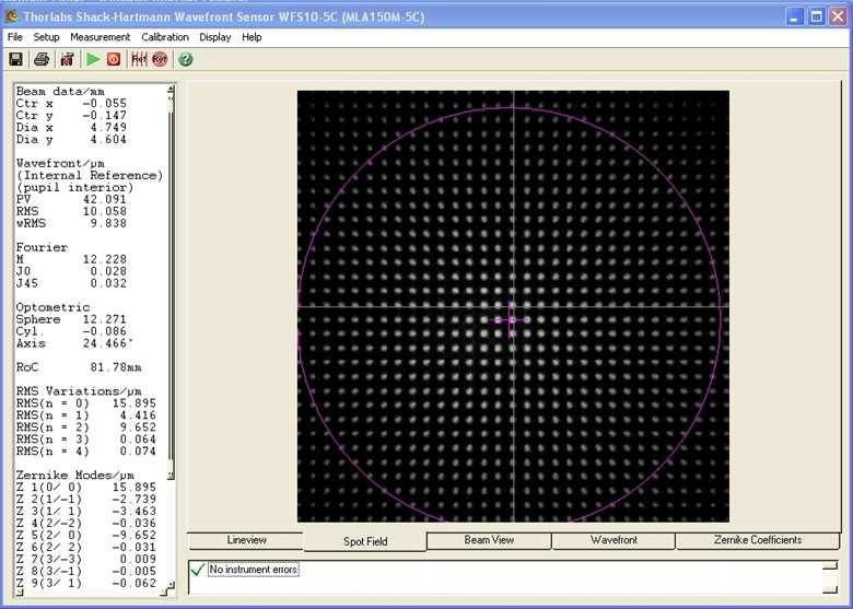
6 Measuring aberrations Shack-Hartmann wavefront sensor tan wavefront slope


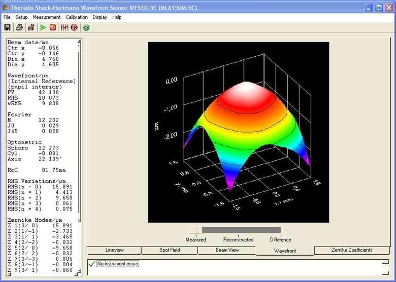
7 Measuring aberrations Zernike coefficients (for systems with circular pupils) coefficient Zernike mode Zernike mode 4 corresponds to defocus, 5 and 6 to astigmatism, 7 and 8 to coma
8 Shaping light Adaptive optics We need an element capable of adapting to the wavefront variations Deformable mirrors Spatial light modulator Others
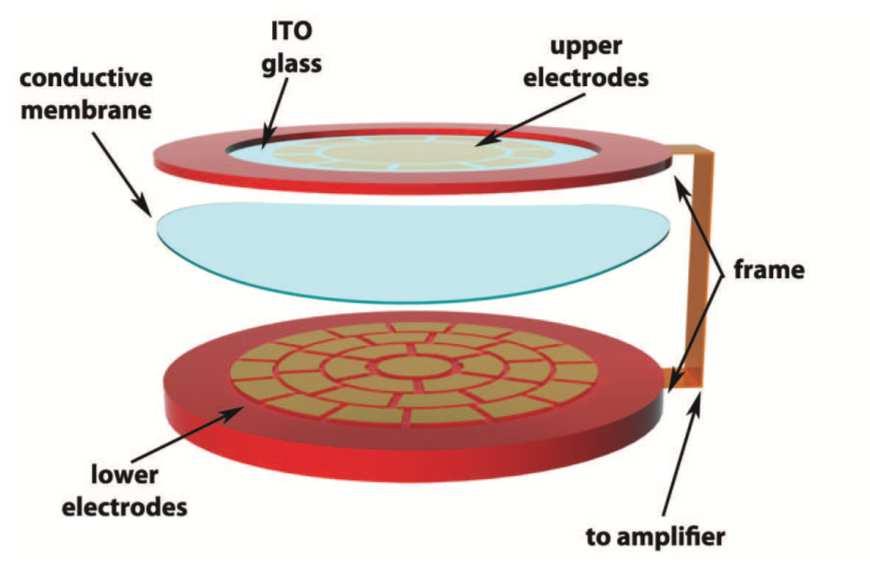
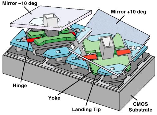
9 Deformable mirrors Membranes Micromirrors
 99, 5789")
10 M. Booth et al., PNAS (2002) 99, 5789 Deformable membrane
11 Where is the wavefront sensor? In microscopy: Difficult to find a guide star (a point reference) Need to exclude out of focus light Dual pass nature of the microscope

12 Sensorless methods are preferred M. Booth et al., Optics & Photonics News (2012)


13 Deformable micromirror No correction Aberration correction 3D reconstruction of a 40µm-thick slice in a whole fixed mouse embryo D. Débarre et al., Opt. Lett. (2009) 34, 2495


14 SLM Polarization and wavelength dependence: mostly used in two-photon microscopy


15 SLM Through 14 µm retina Through 25 µm retina confocal STED STED AO confocal STED STED AO T.J.. Gould et al., Opt. Exp. (2012) 20, 20998


16 Beyond correcting Focusing on strongly scattering media I.M. Vellekoop et al., Opt. Lett. (2007) 32, 2309

17 Beyond correcting Simultaneous excitation of dendritic spines by using multiple foci V. Nikolenko et al., Front. Neural Circ. (2008) 2, 2309

18 Other adaptive optical methods Tradeoff between depth of field and resolution low NA High NA 1/ 1/


19 Changing focus: varifocal lenses z-focus control


20 Changing focus: varifocal lenses Optotune Varioptic C.A. Lopez et al., Nat. Photon (2008) 2, 610 TAG lens

 lens RF signal 30 mm 25")


21 High-speed varifocal lens Acoustically-driven liquid lens: Tunable Acoustic Gradient (TAG) lens RF signal 30 mm 25 mm Periodic standing wave in the fluid density, and consequently, the index of refraction E. McLeod et al. Opt. Lett., (2006) 31, 3155
22
23 Understanding the TAG refractive index change n(r n(r,t ),t ) n Close to the lens center: n+ 2 n ωr 2 4 ccs s A 2 n J 0 + na A r sin sin ( ωt( ) ωt ) 0 0 parabolic lens 1 Optical Power = = f(t ) Ln 2c ω 2 A 2 s sin ( ωt ) M. Duocastella et al. J. PhysD., (2012) 46, radial position
24 Lens power versus time TAG characteristics f = 143 khz A = 10 V pp Wavefront versus time Zernike modes versus time Lens continuously changing focus at a rate given by RF signal The amplitude of the RF signal allows controlling the range of lens power
25 Lens power versus time TAG characteristics power time By appropriate synchronization between light pulses and TAG, it is possible to select any desired optical power within a range


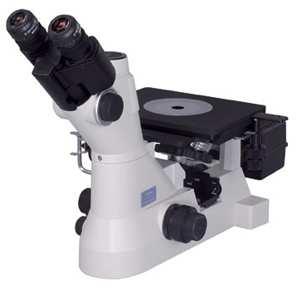
26 TAG-enabled microscope Simply place the TAG lens in the imaging path between the tube lens and the objective
27 Microscope operation To capture a sharp image at each focal position: pulsed light source Change delay between light and lens to select a focal plane Focal position To increase contrast, multiple light pulses synchronized with the TAG lens C.B. Arnold, C. Theriault, M. Duocastella, Patent application 61/552,723 (2011)

28 Electronic focus control By simply changing the delay we can select a desired focal length 10x objective, A = 10 V pp, f=143 khz 100 µm Surface Height Time delay 30 º


29 Electronic focus control Electronically scanned focus on histological specimens Kidney, 20x Liver, 20x Lung, 50x
30 Scanning range 4 mm A=10 V Range of scanning depends on the magnification of the microscope objective Model this using geometric optics 80 µm d: distance between objective and TAG M: objective magnification δ: TAG maximum optical power f tubelens : focal length of the tube lens Scanning range = M 2 δ 2f 2 tube lens 2 TAG δ TAG ( M d f ) 2 tube lens > 4 mm for modest driving amplitude

31 Can we do better? Simultaneous capture of multiple and selectable focal planes Use color CCD chip + colored illumination to capture single image but split based on pixel type Simultaneous acquisition A A B

32 Simultaneous capture multiple planes Focal position Two light sources Red: λ=625 nm Blue: λ=465 nm τ = 300 ns
 17, 050505")
33 Imaging beads LOC Imaging 15 µm beads flowing through 2 channels separated by 1 mm Plane 1 Plane 2 M. Duocastella et al., J. Biom. Optics (2012) 17,


34 5 x objective Composite image Using Red and Blue light gives purple composite image M. Duocastella et al., J. Biom. Optics (2012) 17, μm


35 Separating color channels Blue channel: Red channel: 10 x objective Video is real time 100 μm We can image both sets of beads simultaneously
36 About adaptive optics Powerful method to correct for aberrations in optical systems Traditional correction approach is based on direct sensing. In microscopy, indirect sensing is preferred It is possible to go beyond correction and to use AO for enhanced speed imaging, 3D microscopy
37 Non-conventional beam shapes One solution of the Helmholtz equation: are simply plane waves: In the paraxial approximation and using Cartesian coordinates, we can obtain:

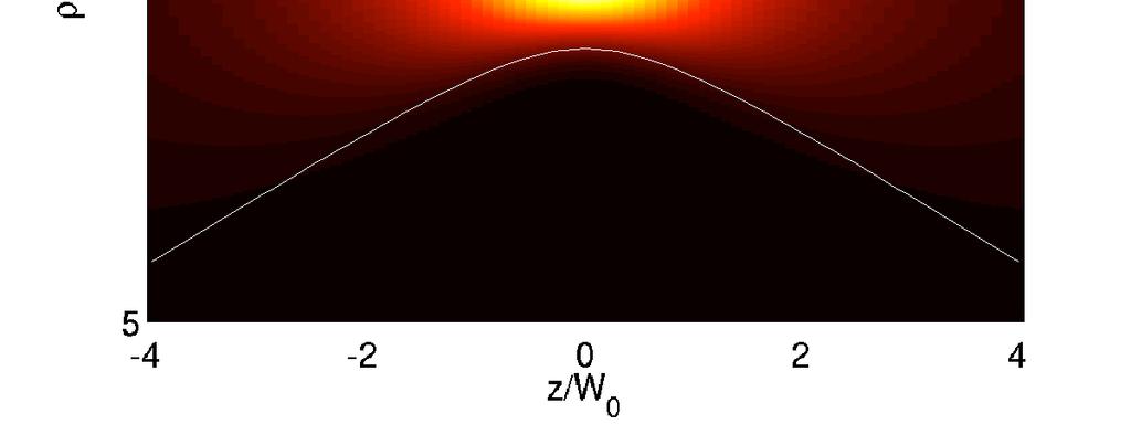
38 Gaussian beam

39 Bessel beam The solution of the Helmholtz equation in cylindrical coordinates: J0 J1
 T.A. Planchon et al., Nat.")
40 Non-diffracting beam Enhanced imaging in SPIM M. Duocastella et al., Laser & Photon Rev. (2012) T.A. Planchon et al., Nat. Methods (2011)
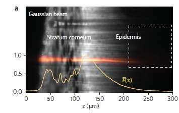
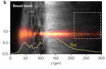
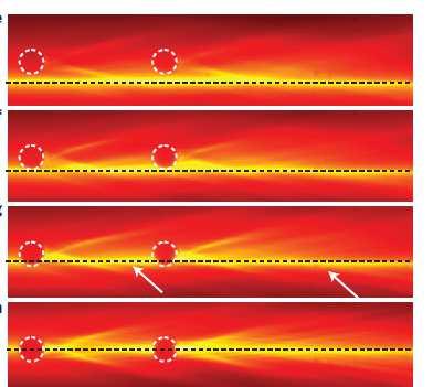
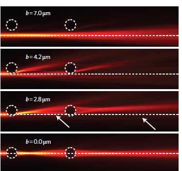
41 Self-healing properties Bessel beam Gaussian beam F.O. Fahrbarch et al., Nat. Photon (2010)


42 Other non-diffracting beams? Mathieu beams Airy beams Why don t you use them in microscopy?
Aberrations and adaptive optics for biomedical microscopes
 Aberrations and adaptive optics for biomedical microscopes Martin Booth Department of Engineering Science And Centre for Neural Circuits and Behaviour University of Oxford Outline Rays, wave fronts and
Martin J. Booth, Delphine Débarre and Alexander Jesacher. Adaptive Optics for
 Martin J. Booth, Delphine Débarre and Alexander Jesacher Adaptive Optics for Over the last decade, researchers have applied adaptive optics a technology that was originally conceived for telescopes to
Ron Liu OPTI521-Introductory Optomechanical Engineering December 7, 2009
 Synopsis of METHOD AND APPARATUS FOR IMPROVING VISION AND THE RESOLUTION OF RETINAL IMAGES by David R. Williams and Junzhong Liang from the US Patent Number: 5,777,719 issued in July 7, 1998 Ron Liu OPTI521-Introductory
Rapid Adaptive Optical Recovery of Optimal Resolution over Large Volumes
 SUPPLEMENTARY MATERIAL Rapid Adaptive Optical Recovery of Optimal Resolution over Large Volumes Kai Wang, Dan Milkie, Ankur Saxena, Peter Engerer, Thomas Misgeld, Marianne E. Bronner, Jeff Mumm, and Eric
Nature Methods: doi: /nmeth Supplementary Figure 1. Schematic of 2P-ISIM AO optical setup.
 Supplementary Figure 1 Schematic of 2P-ISIM AO optical setup. Excitation from a femtosecond laser is passed through intensity control and shuttering optics (1/2 λ wave plate, polarizing beam splitting
Adaptive Optics. J Mertz Boston University
 Adaptive Optics J Mertz Boston University n 1 n 2 Defocus Bad focus Large peak-to-valley Defocus correction n 1 n 2 Bad focus Small peak-to-valley Spherical aberration correction n 1 n 2 Good focus ?
Lecture 2: Geometrical Optics. Geometrical Approximation. Lenses. Mirrors. Optical Systems. Images and Pupils. Aberrations.
 Lecture 2: Geometrical Optics Outline 1 Geometrical Approximation 2 Lenses 3 Mirrors 4 Optical Systems 5 Images and Pupils 6 Aberrations Christoph U. Keller, Leiden Observatory, keller@strw.leidenuniv.nl
Adaptive Optics for LIGO
 Adaptive Optics for LIGO Justin Mansell Ginzton Laboratory LIGO-G990022-39-M Motivation Wavefront Sensor Outline Characterization Enhancements Modeling Projections Adaptive Optics Results Effects of Thermal
Lecture 2: Geometrical Optics. Geometrical Approximation. Lenses. Mirrors. Optical Systems. Images and Pupils. Aberrations.
 Lecture 2: Geometrical Optics Outline 1 Geometrical Approximation 2 Lenses 3 Mirrors 4 Optical Systems 5 Images and Pupils 6 Aberrations Christoph U. Keller, Leiden Observatory, keller@strw.leidenuniv.nl
Administrative details:
 Administrative details: Anything from your side? www.photonics.ethz.ch 1 What are we actually doing here? Optical imaging: Focusing by a lens Angular spectrum Paraxial approximation Gaussian beams Method
Applications of Adaptive Optics in Fluorescence Microscopy and Ophthalmology
 Applications of Adaptive Optics in Fluorescence Microscopy and Ophthalmology Audrius JASAITIS Imagine Optic (Orsay, France) Application Specialist Microscopy ajasaitis@imagine-optic.com Imagine Optic -
Lecture 4: Geometrical Optics 2. Optical Systems. Images and Pupils. Rays. Wavefronts. Aberrations. Outline
 Lecture 4: Geometrical Optics 2 Outline 1 Optical Systems 2 Images and Pupils 3 Rays 4 Wavefronts 5 Aberrations Christoph U. Keller, Leiden University, keller@strw.leidenuniv.nl Lecture 4: Geometrical
3.0 Alignment Equipment and Diagnostic Tools:
 3.0 Alignment Equipment and Diagnostic Tools: Alignment equipment The alignment telescope and its use The laser autostigmatic cube (LACI) interferometer A pin -- and how to find the center of curvature
Metrology and Sensing
 Metrology and Sensing Lecture 7: Wavefront sensors 2016-11-29 Herbert Gross Winter term 2016 www.iap.uni-jena.de 2 Preliminary Schedule No Date Subject Detailed Content 1 18.10. Introduction Introduction,
J. C. Wyant Fall, 2012 Optics Optical Testing and Testing Instrumentation
 J. C. Wyant Fall, 2012 Optics 513 - Optical Testing and Testing Instrumentation Introduction 1. Measurement of Paraxial Properties of Optical Systems 1.1 Thin Lenses 1.1.1 Measurements Based on Image Equation
EE119 Introduction to Optical Engineering Spring 2003 Final Exam. Name:
 EE119 Introduction to Optical Engineering Spring 2003 Final Exam Name: SID: CLOSED BOOK. THREE 8 1/2 X 11 SHEETS OF NOTES, AND SCIENTIFIC POCKET CALCULATOR PERMITTED. TIME ALLOTTED: 180 MINUTES Fundamental
Nature Neuroscience: doi: /nn Supplementary Figure 1. Optimized Bessel foci for in vivo volume imaging.
 Supplementary Figure 1 Optimized Bessel foci for in vivo volume imaging. (a) Images taken by scanning Bessel foci of various NAs, lateral and axial FWHMs: (Left panels) in vivo volume images of YFP + neurites
WaveMaster IOL. Fast and accurate intraocular lens tester
 WaveMaster IOL Fast and accurate intraocular lens tester INTRAOCULAR LENS TESTER WaveMaster IOL Fast and accurate intraocular lens tester WaveMaster IOL is a new instrument providing real time analysis
EE119 Introduction to Optical Engineering Fall 2009 Final Exam. Name:
 EE119 Introduction to Optical Engineering Fall 2009 Final Exam Name: SID: CLOSED BOOK. THREE 8 1/2 X 11 SHEETS OF NOTES, AND SCIENTIFIC POCKET CALCULATOR PERMITTED. TIME ALLOTTED: 180 MINUTES Fundamental
Enhancement of the lateral resolution and the image quality in a line-scanning tomographic optical microscope
 Summary of the PhD thesis Enhancement of the lateral resolution and the image quality in a line-scanning tomographic optical microscope Author: Dudás, László Supervisors: Prof. Dr. Szabó, Gábor and Dr.
Why is There a Black Dot when Defocus = 1λ?
 Why is There a Black Dot when Defocus = 1λ? W = W 020 = a 020 ρ 2 When a 020 = 1λ Sag of the wavefront at full aperture (ρ = 1) = 1λ Sag of the wavefront at ρ = 0.707 = 0.5λ Area of the pupil from ρ =
Point Spread Function. Confocal Laser Scanning Microscopy. Confocal Aperture. Optical aberrations. Alternative Scanning Microscopy
 Bi177 Lecture 5 Adding the Third Dimension Wide-field Imaging Point Spread Function Deconvolution Confocal Laser Scanning Microscopy Confocal Aperture Optical aberrations Alternative Scanning Microscopy
Bio 407. Applied microscopy. Introduction into light microscopy. José María Mateos. Center for Microscopy and Image Analysis
 Center for Microscopy and Image Analysis Bio 407 Applied Introduction into light José María Mateos Fundamentals of light Compound microscope Microscope composed of an objective and an additional lens (eyepiece,
Practical Flatness Tech Note
 Practical Flatness Tech Note Understanding Laser Dichroic Performance BrightLine laser dichroic beamsplitters set a new standard for super-resolution microscopy with λ/10 flatness per inch, P-V. We ll
Heisenberg) relation applied to space and transverse wavevector
 relation applied to space and transverse wavevector") 2. Optical Microscopy 2.1 Principles A microscope is in principle nothing else than a simple lens system for magnifying small objects. The first lens, called the objective, has a short focal length (a
2. Optical Microscopy 2.1 Principles A microscope is in principle nothing else than a simple lens system for magnifying small objects. The first lens, called the objective, has a short focal length (a
Adaptive optimisation of illumination beam profiles in fluorescence microscopy
 Adaptive optimisation of illumination beam profiles in fluorescence microscopy T. J. Mitchell a, C. D. Saunter a, W. O Nions a, J. M. Girkin a, G. D. Love a a Centre for Advanced nstrumentation & Biophysical
Applied Optics. , Physics Department (Room #36-401) , ,
 , ,") Applied Optics Professor, Physics Department (Room #36-401) 2290-0923, 019-539-0923, shsong@hanyang.ac.kr Office Hours Mondays 15:00-16:30, Wednesdays 15:00-16:30 TA (Ph.D. student, Room #36-415) 2290-0921,
Applied Optics Professor, Physics Department (Room #36-401) 2290-0923, 019-539-0923, shsong@hanyang.ac.kr Office Hours Mondays 15:00-16:30, Wednesdays 15:00-16:30 TA (Ph.D. student, Room #36-415) 2290-0921,
Lecture 3: Geometrical Optics 1. Spherical Waves. From Waves to Rays. Lenses. Chromatic Aberrations. Mirrors. Outline
 Lecture 3: Geometrical Optics 1 Outline 1 Spherical Waves 2 From Waves to Rays 3 Lenses 4 Chromatic Aberrations 5 Mirrors Christoph U. Keller, Leiden Observatory, keller@strw.leidenuniv.nl Lecture 3: Geometrical
Geometrical Optics for AO Claire Max UC Santa Cruz CfAO 2009 Summer School
 Geometrical Optics for AO Claire Max UC Santa Cruz CfAO 2009 Summer School Page 1 Some tools for active learning In-class conceptual questions will aim to engage you in more active learning and provide
Optical Components for Laser Applications. Günter Toesko - Laserseminar BLZ im Dezember
 Günter Toesko - Laserseminar BLZ im Dezember 2009 1 Aberrations An optical aberration is a distortion in the image formed by an optical system compared to the original. It can arise for a number of reasons
Dynamic beam shaping with programmable diffractive optics
 Dynamic beam shaping with programmable diffractive optics Bosanta R. Boruah Dept. of Physics, GU Page 1 Outline of the talk Introduction Holography Programmable diffractive optics Laser scanning confocal
Wavefront Sensing In Other Disciplines. 15 February 2003 Jerry Nelson, UCSC Wavefront Congress
 Wavefront Sensing In Other Disciplines 15 February 2003 Jerry Nelson, UCSC Wavefront Congress QuickTime and a Photo - JPEG decompressor are needed to see this picture. 15feb03 Nelson wavefront sensing
Very short introduction to light microscopy and digital imaging
 Very short introduction to light microscopy and digital imaging Hernan G. Garcia August 1, 2005 1 Light Microscopy Basics In this section we will briefly describe the basic principles of operation and
Resolution. Diffraction from apertures limits resolution. Rayleigh criterion θ Rayleigh = 1.22 λ/d 1 peak at 2 nd minimum. θ f D
 Microscopy Outline 1. Resolution and Simple Optical Microscope 2. Contrast enhancement: Dark field, Fluorescence (Chelsea & Peter), Phase Contrast, DIC 3. Newer Methods: Scanning Tunneling microscopy (STM),
WaveMaster IOL. Fast and Accurate Intraocular Lens Tester
 WaveMaster IOL Fast and Accurate Intraocular Lens Tester INTRAOCULAR LENS TESTER WaveMaster IOL Fast and accurate intraocular lens tester WaveMaster IOL is an instrument providing real time analysis of
Direct wavefront sensing in adaptive optical microscopy using backscattered light
 Direct wavefront sensing in adaptive optical microscopy using backscattered light Saad A. Rahman 1 and Martin J. Booth 1,2, * 1 Department of Engineering Science, University of Oxford, Parks Road, Oxford,
APPLICATION NOTE
 THE PHYSICS BEHIND TAG OPTICS TECHNOLOGY AND THE MECHANISM OF ACTION OF APPLICATION NOTE 12-001 USING SOUND TO SHAPE LIGHT Page 1 of 6 Tutorial on How the TAG Lens Works This brief tutorial explains the
Study of self-interference incoherent digital holography for the application of retinal imaging
 Study of self-interference incoherent digital holography for the application of retinal imaging Jisoo Hong and Myung K. Kim Department of Physics, University of South Florida, Tampa, FL, US 33620 ABSTRACT
Introduction to light microscopy
 Center for Microscopy and Image Anaylsis Introduction to light microscopy Basic concepts of imaging with light Urs Ziegler ziegler@zmb.uzh.ch Light interacting with matter Absorbtion Refraction Diffraction
Light microscopy BMB 173, Lecture 14, Feb. 21, 2018
 Light microscopy The Structural Biology Continuum Next two lectures: Light microscopy Many slides taken from Scott Fraser, Murphy s Fundamentals of light microscopy, Alberts Molecular Biology of the Cell,
Dynamic closed-loop system for focus tracking using a spatial light modulator and a deformable membrane mirror
 Dynamic closed-loop system for focus tracking using a spatial light modulator and a deformable membrane mirror Amanda J. Wright, Brett A. Patterson, Simon P. Poland, John M. Girkin Institute of Photonics,
More fancy SPIM, Even fancier SPIM
 More fancy SPIM, Even fancier SPIM Last class Light sheet microscopy Fancy SPIM (ispim, dspim, etc ) This class Multi camera SPIM SIM SPIM Bessels d x,y = λ em 2 NA d z = 2 NA λ ex + n(1 cosθ λ em 1 IsoView
Image Formation. Light from distant things. Geometrical optics. Pinhole camera. Chapter 36
 Light from distant things Chapter 36 We learn about a distant thing from the light it generates or redirects. The lenses in our eyes create images of objects our brains can process. This chapter concerns
SENSOR+TEST Conference SENSOR 2009 Proceedings II
 B8.4 Optical 3D Measurement of Micro Structures Ettemeyer, Andreas; Marxer, Michael; Keferstein, Claus NTB Interstaatliche Hochschule für Technik Buchs Werdenbergstr. 4, 8471 Buchs, Switzerland Introduction
3D light microscopy techniques
 3D light microscopy techniques The image of a point is a 3D feature In-focus image Out-of-focus image The image of a point is not a point Point Spread Function (PSF) 1D imaging 2D imaging 3D imaging Resolution
Microscopy. Lecture 2: Optical System of the Microscopy II Herbert Gross. Winter term
 Microscopy Lecture 2: Optical System of the Microscopy II 212-1-22 Herbert Gross Winter term 212 www.iap.uni-jena.de Preliminary time schedule 2 No Date Main subject Detailed topics Lecturer 1 15.1. Optical
INTRODUCTION TO MICROSCOPY. Urs Ziegler THE PROBLEM
 INTRODUCTION TO MICROSCOPY Urs Ziegler ziegler@zmb.uzh.ch THE PROBLEM 1 ORGANISMS ARE LARGE LIGHT AND ELECTRONS: ELECTROMAGNETIC WAVES v = Wavelength ( ) Speed (v) Frequency ( ) Amplitude (A) Propagation
In a confocal fluorescence microscope, light from a laser is
 Adaptive aberration correction in a confocal microscope Martin J. Booth*, Mark A. A. Neil, Rimas Juškaitis, and Tony Wilson Department of Engineering Science, University of Oxford, Parks Road, Oxford OX1
3D light microscopy techniques
 3D light microscopy techniques The image of a point is a 3D feature In-focus image Out-of-focus image The image of a point is not a point Point Spread Function (PSF) 1D imaging 1 1 2! NA = 0.5! NA 2D imaging
A wavefront generator for complex pupil function synthesis and point spread function engineering
 Journal of Microscopy, Vol. 197, Pt 3, March 2000, pp. 219±223. Received 27 September 1999; accepted 30 November 1999 SHORT COMMUNICATION A wavefront generator for complex pupil function synthesis and
Optical Design of. Microscopes. George H. Seward. Tutorial Texts in Optical Engineering Volume TT88. SPIE PRESS Bellingham, Washington USA
 Optical Design of Microscopes George H. Seward Tutorial Texts in Optical Engineering Volume TT88 SPIE PRESS Bellingham, Washington USA Preface xiii Chapter 1 Optical Design Concepts /1 1.1 A Value Proposition
Confocal Imaging Through Scattering Media with a Volume Holographic Filter
 Confocal Imaging Through Scattering Media with a Volume Holographic Filter Michal Balberg +, George Barbastathis*, Sergio Fantini % and David J. Brady University of Illinois at Urbana-Champaign, Urbana,
Adaptive optics two-photon fluorescence microscopy
 Adaptive optics two-photon fluorescence microscopy Yaopeng Zhou 1, Thomas Bifano 1 and Charles Lin 2 1. Manufacturing Engineering Department, Boston University 15 Saint Mary's Street, Brookline MA, 02446
Development of a new multi-wavelength confocal surface profilometer for in-situ automatic optical inspection (AOI)
") Development of a new multi-wavelength confocal surface profilometer for in-situ automatic optical inspection (AOI) Liang-Chia Chen 1#, Chao-Nan Chen 1 and Yi-Wei Chang 1 1. Institute of Automation Technology,
Development of a new multi-wavelength confocal surface profilometer for in-situ automatic optical inspection (AOI) Liang-Chia Chen 1#, Chao-Nan Chen 1 and Yi-Wei Chang 1 1. Institute of Automation Technology,
MALA MATEEN. 1. Abstract
 IMPROVING THE SENSITIVITY OF ASTRONOMICAL CURVATURE WAVEFRONT SENSOR USING DUAL-STROKE CURVATURE: A SYNOPSIS MALA MATEEN 1. Abstract Below I present a synopsis of the paper: Improving the Sensitivity of
Nature Methods: doi: /nmeth Supplementary Figure 1
 . Supplementary Figure 1 Schematics and characterization of our AO two-photon fluorescence microscope. (a) Essential components of our AO two-photon fluorescence microscope: Ti:Sapphire laser; optional
Simple characterisation of a deformable mirror inside a high numerical aperture microscope using phase diversity
 Journal of Microscopy, 2011 Received 6 May 2011, accepted 17 May 2011 doi: 10.1111/j.1365-2818.2011.03518.x Simple characterisation of a deformable mirror inside a high numerical aperture microscope using
Stereoscopic Hologram
 Stereoscopic Hologram Joonku Hahn Kyungpook National University Outline: 1. Introduction - Basic structure of holographic display - Wigner distribution function 2. Design of Stereoscopic Hologram - Optical
INTRODUCTION TO ABERRATIONS IN OPTICAL IMAGING SYSTEMS
 INTRODUCTION TO ABERRATIONS IN OPTICAL IMAGING SYSTEMS JOSE SASIÄN University of Arizona ШШ CAMBRIDGE Щ0 UNIVERSITY PRESS Contents Preface Acknowledgements Harold H. Hopkins Roland V. Shack Symbols 1 Introduction
DESIGN NOTE: DIFFRACTION EFFECTS
 NASA IRTF / UNIVERSITY OF HAWAII Document #: TMP-1.3.4.2-00-X.doc Template created on: 15 March 2009 Last Modified on: 5 April 2010 DESIGN NOTE: DIFFRACTION EFFECTS Original Author: John Rayner NASA Infrared
Cardinal Points of an Optical System--and Other Basic Facts
 Cardinal Points of an Optical System--and Other Basic Facts The fundamental feature of any optical system is the aperture stop. Thus, the most fundamental optical system is the pinhole camera. The image
Chapter 1. Basic Electron Optics (Lecture 2)
") Chapter 1. Basic Electron Optics (Lecture 2) Basic concepts of microscope (Cont ) Fundamental properties of electrons Electron Scattering Instrumentation Basic conceptions of microscope (Cont ) Ray diagram
Chapter 1. Basic Electron Optics (Lecture 2) Basic concepts of microscope (Cont ) Fundamental properties of electrons Electron Scattering Instrumentation Basic conceptions of microscope (Cont ) Ray diagram
Theoretical modeling and evaluation of the axial resolution of the adaptive optics scanning laser ophthalmoscope
 Journal of Biomedical Optics 9(1), 132 138 (January/February 2004) Theoretical modeling and evaluation of the axial resolution of the adaptive optics scanning laser ophthalmoscope Krishnakumar Venkateswaran
Adaptive optics in digital micromirror based confocal microscopy P. Pozzi *a, D.Wilding a, O.Soloviev a,b, G.Vdovin a,b, M.
 Adaptive optics in digital micromirror based confocal microscopy P. Pozzi *a, D.Wilding a, O.Soloviev a,b, G.Vdovin a,b, M.Verhaegen a a Delft Center for Systems and Control, Delft University of Technology,
Advanced Lens Design
 Advanced Lens Design Lecture 3: Aberrations I 214-11-4 Herbert Gross Winter term 214 www.iap.uni-jena.de 2 Preliminary Schedule 1 21.1. Basics Paraxial optics, imaging, Zemax handling 2 28.1. Optical systems
Explanation of Aberration and Wavefront
 Explanation of Aberration and Wavefront 1. What Causes Blur? 2. What is? 4. What is wavefront? 5. Hartmann-Shack Aberrometer 6. Adoption of wavefront technology David Oh 1. What Causes Blur? 2. What is?
SUPPLEMENTARY INFORMATION
 Optically reconfigurable metasurfaces and photonic devices based on phase change materials S1: Schematic diagram of the experimental setup. A Ti-Sapphire femtosecond laser (Coherent Chameleon Vision S)
4th International Congress of Wavefront Sensing and Aberration-free Refractive Correction ADAPTIVE OPTICS FOR VISION: THE EYE S ADAPTATION TO ITS
 4th International Congress of Wavefront Sensing and Aberration-free Refractive Correction (Supplement to the Journal of Refractive Surgery; June 2003) ADAPTIVE OPTICS FOR VISION: THE EYE S ADAPTATION TO
Microscopy. Matti Hotokka Department of Physical Chemistry Åbo Akademi University
 Microscopy Matti Hotokka Department of Physical Chemistry Åbo Akademi University What s coming Anatomy of a microscope Modes of illumination Practicalities Special applications Basic microscope Ocular
Introduction to light microscopy
 Center for Microscopy and Image Anaylsis Introduction to light Basic concepts of imaging with light Urs Ziegler ziegler@zmb.uzh.ch Microscopy with light 1 Light interacting with matter Absorbtion Refraction
Supplementary Figure 1. Effect of the spacer thickness on the resonance properties of the gold and silver metasurface layers.
 Supplementary Figure 1. Effect of the spacer thickness on the resonance properties of the gold and silver metasurface layers. Finite-difference time-domain calculations of the optical transmittance through
Wavefront sensing by an aperiodic diffractive microlens array
 Wavefront sensing by an aperiodic diffractive microlens array Lars Seifert a, Thomas Ruppel, Tobias Haist, and Wolfgang Osten a Institut für Technische Optik, Universität Stuttgart, Pfaffenwaldring 9,
Spatial Light Modulators: what are the needs for (complex) optical wavefront shaping through complex media
 optical wavefront shaping through complex media") Spatial Light Modulators: what are the needs for (complex) optical wavefront shaping through complex media Emmanuel Bossy OPTIMA (Optics and Imaging) Interdisciplinary Physics Lab., Univ. Grenoble Alpes
Spatial Light Modulators: what are the needs for (complex) optical wavefront shaping through complex media Emmanuel Bossy OPTIMA (Optics and Imaging) Interdisciplinary Physics Lab., Univ. Grenoble Alpes
Zero Focal Shift in High Numerical Aperture Focusing of a Gaussian Laser Beam through Multiple Dielectric Interfaces. Ali Mahmoudi
 1 Zero Focal Shift in High Numerical Aperture Focusing of a Gaussian Laser Beam through Multiple Dielectric Interfaces Ali Mahmoudi a.mahmoudi@qom.ac.ir & amahmodi@yahoo.com Laboratory of Optical Microscopy,
Basics of confocal imaging (part I)
") Basics of confocal imaging (part I) Swiss Institute of Technology (EPFL) Faculty of Life Sciences Head of BIOIMAGING AND OPTICS BIOP arne.seitz@epfl.ch Lateral resolution BioImaging &Optics Platform Light
Basics of confocal imaging (part I) Swiss Institute of Technology (EPFL) Faculty of Life Sciences Head of BIOIMAGING AND OPTICS BIOP arne.seitz@epfl.ch Lateral resolution BioImaging &Optics Platform Light
2. Adaptive Optical Microscopy using Direct Wavefront Sensing 2.1 Introduction In this chapter we will review adaptive optics (AO) in biological
 in biological") 2. Adaptive Optical Microscopy using Direct Wavefront Sensing 2.1 Introduction In this chapter we will review adaptive optics (AO) in biological imaging using direct wavefront measurement. Here light from
2. Adaptive Optical Microscopy using Direct Wavefront Sensing 2.1 Introduction In this chapter we will review adaptive optics (AO) in biological imaging using direct wavefront measurement. Here light from
Lens Design I. Lecture 5: Advanced handling I Herbert Gross. Summer term
 Lens Design I Lecture 5: Advanced handling I 2018-05-17 Herbert Gross Summer term 2018 www.iap.uni-jena.de 2 Preliminary Schedule - Lens Design I 2018 1 12.04. Basics 2 19.04. Properties of optical systems
Optical Design with Zemax
 Optical Design with Zemax Lecture : Correction II 3--9 Herbert Gross Summer term www.iap.uni-jena.de Correction II Preliminary time schedule 6.. Introduction Introduction, Zemax interface, menues, file
Scanless two-photon excitation of channelrhodopsin-2
 Nature Methods Scanless two-photon excitation of channelrhodopsin- Eirini Papagiakoumou, Francesca Anselmi, Aurelien Begue, Vincent de Sars, Jesper Glückstad, Ehud Y Isacoff & Valentina Emiliani Supplementary
GEOMETRICAL OPTICS AND OPTICAL DESIGN
 GEOMETRICAL OPTICS AND OPTICAL DESIGN Pantazis Mouroulis Associate Professor Center for Imaging Science Rochester Institute of Technology John Macdonald Senior Lecturer Physics Department University of
VISUAL PHYSICS ONLINE DEPTH STUDY: ELECTRON MICROSCOPES
 VISUAL PHYSICS ONLINE DEPTH STUDY: ELECTRON MICROSCOPES Shortly after the experimental confirmation of the wave properties of the electron, it was suggested that the electron could be used to examine objects
Variable microinspection system. system125
 Variable microinspection system system125 Variable micro-inspection system Characteristics Large fields, high NA The variable microinspection system mag.x system125 stands out from conventional LD inspection
Chapter Ray and Wave Optics
 109 Chapter Ray and Wave Optics 1. An astronomical telescope has a large aperture to [2002] reduce spherical aberration have high resolution increase span of observation have low dispersion. 2. If two
Department of Mechanical and Aerospace Engineering, Princeton University Department of Astrophysical Sciences, Princeton University ABSTRACT
 Phase and Amplitude Control Ability using Spatial Light Modulators and Zero Path Length Difference Michelson Interferometer Michael G. Littman, Michael Carr, Jim Leighton, Ezekiel Burke, David Spergel
Subjective Image Quality Metrics from The Wave Aberration
 Subjective Image Quality Metrics from The Wave Aberration David R. Williams William G. Allyn Professor of Medical Optics Center For Visual Science University of Rochester Commercial Relationship: Bausch
Tissue Preparation ORGANISM IMAGE TISSUE PREPARATION. 1) Fixation: halts cell metabolism, preserves cell/tissue structure
 Fixation: halts cell metabolism, preserves cell/tissue structure") Lab starts this week! ANNOUNCEMENTS - Tuesday or Wednesday 1:25 ISB 264 - Read Lab 1: Microscopy and Imaging (see Web Page) - Getting started on Lab Group project - Organ for investigation - Lab project
Lab starts this week! ANNOUNCEMENTS - Tuesday or Wednesday 1:25 ISB 264 - Read Lab 1: Microscopy and Imaging (see Web Page) - Getting started on Lab Group project - Organ for investigation - Lab project
Characteristics of point-focus Simultaneous Spatial and temporal Focusing (SSTF) as a two-photon excited fluorescence microscopy
 as a two-photon excited fluorescence microscopy") Characteristics of point-focus Simultaneous Spatial and temporal Focusing (SSTF) as a two-photon excited fluorescence microscopy Qiyuan Song (M2) and Aoi Nakamura (B4) Abstracts: We theoretically and experimentally
Characteristics of point-focus Simultaneous Spatial and temporal Focusing (SSTF) as a two-photon excited fluorescence microscopy Qiyuan Song (M2) and Aoi Nakamura (B4) Abstracts: We theoretically and experimentally
Bias errors in PIV: the pixel locking effect revisited.
 Bias errors in PIV: the pixel locking effect revisited. E.F.J. Overmars 1, N.G.W. Warncke, C. Poelma and J. Westerweel 1: Laboratory for Aero & Hydrodynamics, University of Technology, Delft, The Netherlands,
INTRODUCTION THIN LENSES. Introduction. given by the paraxial refraction equation derived last lecture: Thin lenses (19.1) = 1. Double-lens systems
 = 1. Double-lens systems") Chapter 9 OPTICAL INSTRUMENTS Introduction Thin lenses Double-lens systems Aberrations Camera Human eye Compound microscope Summary INTRODUCTION Knowledge of geometrical optics, diffraction and interference,
Chapter 9 OPTICAL INSTRUMENTS Introduction Thin lenses Double-lens systems Aberrations Camera Human eye Compound microscope Summary INTRODUCTION Knowledge of geometrical optics, diffraction and interference,
Examination, TEN1, in courses SK2500/SK2501, Physics of Biomedical Microscopy,
 KTH Applied Physics Examination, TEN1, in courses SK2500/SK2501, Physics of Biomedical Microscopy, 2009-06-05, 8-13, FB51 Allowed aids: Compendium Imaging Physics (handed out) Compendium Light Microscopy
Sensitive measurement of partial coherence using a pinhole array
 1.3 Sensitive measurement of partial coherence using a pinhole array Paul Petruck 1, Rainer Riesenberg 1, Richard Kowarschik 2 1 Institute of Photonic Technology, Albert-Einstein-Strasse 9, 07747 Jena,
a) How big will that physical image of the cells be your camera sensor?
 How big will that physical image of the cells be your camera sensor?") 1. Consider a regular wide-field microscope set up with a 60x, NA = 1.4 objective and a monochromatic digital camera with 8 um pixels, properly positioned in the primary image plane. This microscope is
1. Consider a regular wide-field microscope set up with a 60x, NA = 1.4 objective and a monochromatic digital camera with 8 um pixels, properly positioned in the primary image plane. This microscope is
CHAPTER TWO METALLOGRAPHY & MICROSCOPY
 CHAPTER TWO METALLOGRAPHY & MICROSCOPY 1. INTRODUCTION: Materials characterisation has two main aspects: Accurately measuring the physical, mechanical and chemical properties of materials Accurately measuring
Vision Research at. Validation of a Novel Hartmann-Moiré Wavefront Sensor with Large Dynamic Range. Wavefront Science Congress, Feb.
 Wavefront Science Congress, Feb. 2008 Validation of a Novel Hartmann-Moiré Wavefront Sensor with Large Dynamic Range Xin Wei 1, Tony Van Heugten 2, Nikole L. Himebaugh 1, Pete S. Kollbaum 1, Mei Zhang
 Telecentric Imaging Object space telecentricity stop source: edmund optics The 5 classical Seidel Aberrations First order aberrations Spherical Aberration (~r 4 ) Origin: different focal lengths for different
Flatness of Dichroic Beamsplitters Affects Focus and Image Quality
 Flatness of Dichroic Beamsplitters Affects Focus and Image Quality Flatness of Dichroic Beamsplitters Affects Focus and Image Quality 1. Introduction Even though fluorescence microscopy has become a routine
Compensation of hologram distortion by controlling defocus component in reference beam wavefront for angle multiplexed holograms
 J. Europ. Opt. Soc. Rap. Public. 8, 13080 (2013) www.jeos.org Compensation of hologram distortion by controlling defocus component in reference beam wavefront for angle multiplexed holograms T. Muroi muroi.t-hc@nhk.or.jp
Lens Design I. Lecture 3: Properties of optical systems II Herbert Gross. Summer term
 Lens Design I Lecture 3: Properties of optical systems II 207-04-20 Herbert Gross Summer term 207 www.iap.uni-jena.de 2 Preliminary Schedule - Lens Design I 207 06.04. Basics 2 3.04. Properties of optical
Physics 431 Final Exam Examples (3:00-5:00 pm 12/16/2009) TIME ALLOTTED: 120 MINUTES Name: Signature:
 TIME ALLOTTED: 120 MINUTES Name: Signature:") Physics 431 Final Exam Examples (3:00-5:00 pm 12/16/2009) TIME ALLOTTED: 120 MINUTES Name: PID: Signature: CLOSED BOOK. TWO 8 1/2 X 11 SHEET OF NOTES (double sided is allowed), AND SCIENTIFIC POCKET CALCULATOR
Physics 431 Final Exam Examples (3:00-5:00 pm 12/16/2009) TIME ALLOTTED: 120 MINUTES Name: PID: Signature: CLOSED BOOK. TWO 8 1/2 X 11 SHEET OF NOTES (double sided is allowed), AND SCIENTIFIC POCKET CALCULATOR
Optics of Wavefront. Austin Roorda, Ph.D. University of Houston College of Optometry
 Optics of Wavefront Austin Roorda, Ph.D. University of Houston College of Optometry Geometrical Optics Relationships between pupil size, refractive error and blur Optics of the eye: Depth of Focus 2 mm