Geeetech A30 3D Printer Building Instruction
|
|
|
- Nathan Joseph
- 5 years ago
- Views:
Transcription

1 Geeetech A30 3D Printer Building Instruction
2 Contents Safety Instructions... 1 Preparation Unfold the Box and Check the Package Assembly Wiring Warm Tips...16
3 Safety Instructions Building the printer will require a certain amount of physical dexterity, common sense and a thorough understanding of what you are doing. We have provided this detailed instruction to help you assemble it easily. However, ultimately we cannot be responsible for your health and safety while you are building or operating the printer. Therefore, be sure you are confident in what you are doing prior to commencing with building or buying. Read the entire manual to enable you to make an informed decision. Building and operating involves electricity and all necessary precautions should be taken and adhered to. Check the power input of the power supply unit. You can choose either 110V or 220V according to the power regulation in your country. High temperatures are involved in 3D Printing. The extrusion nozzle of the hot end can run at about 210 C, the heated bed runs at 110 C and the molten plastic extruded will initially be at around 200 C. Therefore, special care and attention should be taken when you are handling these parts of the printer during operation. We wouldn t suggest you to leave your printer running unattended, or at least until you are confident to do so. We are not responsible for any loss, damage, threat, hurt or other negligent result caused by either building or using the printer. 1
4 Preparation 1. Unpack the kit and check if all parts are in the box. Please check the condition of each part since there might be some damage during shipping. To help you with this, there is BOM in the box and each bag is labeled with its part number. 2. Contact our customer service immediately by or through the website if you find any missing or damaged parts. 3. Before your assembly, please read through each chapter of this assembly manual to gain an overall idea of what is involved and how long it might take to complete the assembly job. 4. As a preparation job, you can put all the part in order to save your time, especially the screws and nuts. Do not mix them up. 5. Ensure you have the necessary skills to carry out the assembly job or entrust someone who does. 6. Work on a big firm table or bench in a clean dry well-lit area. 7. Since this kit contains tiny parts, please keep them away from kids under Ask for help if you run into any problems --- our contact details are on the website and we will always do our best to solve any problems encountered. 9. For different batches, some parts of the kits may have changed.if the parts listed in this instruction and what you received is slightly different, please don't worry. These changes will not affect your installation and usage. 10. Please watch the building instruction video athttps://youtu.be/hm_zyanwngw 2


5 1. Unfold the Box and Check the Package Step1. Unfold the package and take all the parts out to check the condition of the items. As you can see, all the parts are packed very carefully. Step 2. Check the materials. Materials in the Foam box Bottom frame parts, Vertical frame parts, Control box 3

6 Materials in the Tool Box 4* M5x20mm hex screws, 4 spring washers, Filament spool, 2* M3x6mm screws,power cable, Blue A-B USB cord, 2* Z axis stator kits, 3D touch stator, Filament detector kit, Ties, Allen key, Pin, Starter filament,spare screw package, TF card Tips: 1. Before assembly, you are advised to put all the parts, especially the screws and nuts in order, which would save you much time in looking for the required parts. 2. The part ID is corresponding to the number labeled on the bag of each part. Some parts may not have labels and you can refer to the pictures on the package list. 2. Assembly Step 1. Prepare the following parts for assembling: Bottom frame parts, vertical frame parts, 4* M5x20mm hex screws and 4 spring washers, 2*Z axis stators Step2. Place the vertical frame parts on the bottom frame one (Note: Just keep the ends of the blue strips on the two frames meet each other.) 4


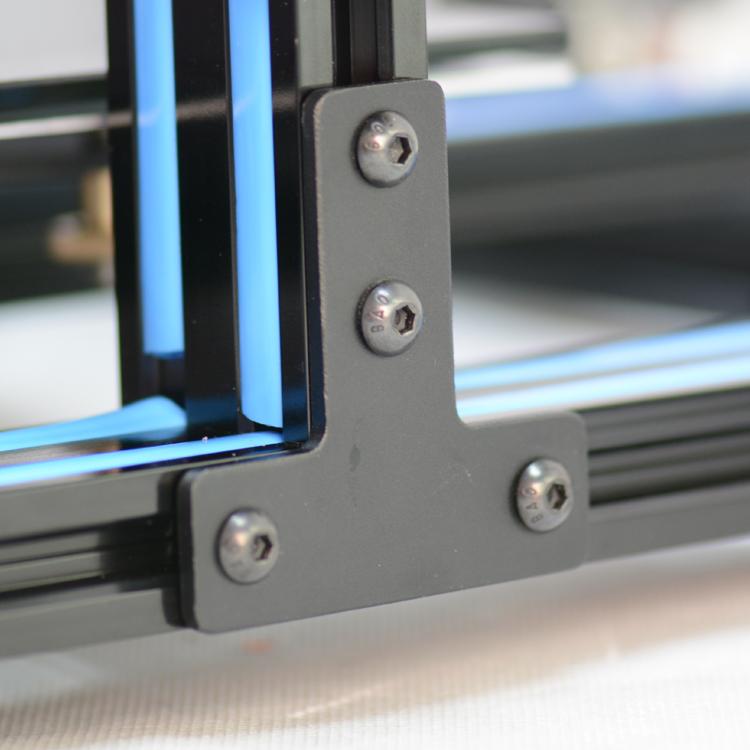
7 Step 3. Use 4* M5x20mm hex screws and 4 spring washers to put the bottom frame parts and the vertical frame parts together. 5
8 Step 4. Fix the two Z axis stators on two sides of the vertical frame respectively. Fasten the screws on the stators in a relatively loose way. Note: Pay attention to the direction of the nuts on the Z axis stator. 6
9 Right 7

10 Left Step 5. Tighten the screws on the Z axis stators. 8


11 3. Wiring Step1. Connect the two wires for X axis stepper motor and endstop. Step 2. Connect the two wires for the extruder motor and filament detector. 9


12 Wire for extruder motor Wire for filament detector Step 3. Connect the wires for Z axis left stepper motor and the endstop; the wire for Z axis right stepper motor. 10


13 Wire for Z axis left motor Wire for Z axis endstop 11


14 Wire for Z axis right motor Step 4. Connect the two wires for Y axis stepper motor and endstop. Step 5. Connect the two wires for the printing head and heatbed to the control box. 12
.")

15 Step 6. Fasten the PTFE pipe (for loading filament). Though the other end of the PTFE pipe is pre-assembled, please make sure thatit reaches the bottom of the printing head. 13

 for A30 by")
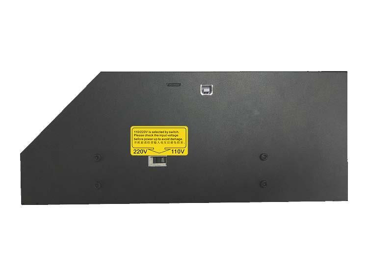
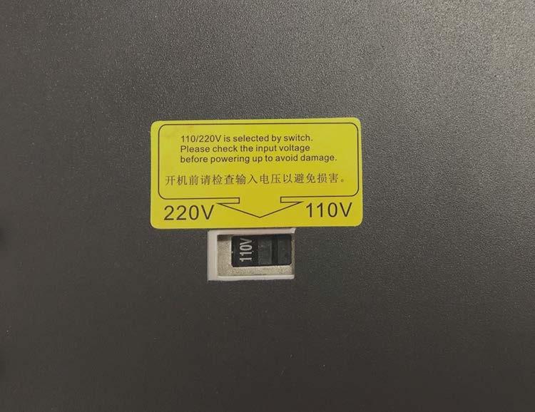
16 Step 7. Attach the filament holder kit to the control box with 2 * M3*6mm. Step 8. Choose the proper voltage (220V / 110V) for A30 by adjusting the switch, according to the power supply standard in your own country. 14
17 15
18 4. Warm Tips Before your maiden print, it is vital that the printer is correctly calibrated. Skipping or rushing this step will result in frustration and failed prints later. More preparation may quicken the speed in doing work. Thus it is important to take the time to make sure the machine is correctly set up. Every machine may have its own calibration procedures and please make reference to the user manual for auto-leveling A30 hotbed. Instead here is a list of key points that should be kept in mind. Frame is stable and correctly aligned. Rods are correctly aligned Belts are taut. Driving wheel turns smoothly. Hotbed is level in relation to the path of the extruder. Filament rolls freely from the spool, without causing too much tension on the extruder. The current for stepper motors is set to the correct level. Wires are correctly connected. Couplings and pulleys are fixed tightly. 16
19 Firmware settings are correct, including: axis movement speeds and acceleration; temperature control; end-stops; motor directions. The point regarding the extruder step rate is vital. Too much extrusion will result in blobs and other imperfections in the print, while too little extrusion will result in gaps and poor inter-layer adhesion. For how to set up the printer, please refer to the user manual. 17
Shenzhen GETECH CO.,LTD GEEETECH. Building Instructions of Geeetech Prusa I3 X
 Building Instructions of Geeetech Prusa I3 X CONTENT CONTENT... 2 Safety Instructions...3 Preparation...4 Unfold the box and check the package list... 5 1. Assemble the threaded rods of Y axis... 6 2.
Assemble Instruction of Geeetech Acrylic Prusa I3. pro C
 Assemble Instruction of Geeetech Acrylic Prusa I3 pro C Safety Instructions Shenzhen GETECH CO.,LTD Building the printer will require a certain amount of physical dexterity, common sense and a thorough
Assemble Instruction of Geeetech Acrylic. Prusa I3 Pro C
 Assemble Instruction of Geeetech Acrylic Prusa I3 Pro C Version 04-11-2016 Safety Instructions Building the printer will require a certain amount of physical dexterity, common sense and a thorough understanding
Assemble Instruction of Geeetech Acrylic Prusa I3. Pro & pro B
 Assemble Instruction of Geeetech Acrylic Prusa I3 Pro & pro B Version 04-11-2016 Safety Instructions Shenzhen GETECH CO.,LTD Building the printer will require a certain amount of physical dexterity, common
Delta Rostock mini G2& G2s Building instruction
 Delta Rostock mini G2& G2s Building instruction Safety Instructions ShenZhen GETECH CO.,LTD Building the printer will require a certain amount of physical dexterity, common sense and a thorough understanding
Geeetech Delta Rostock mini G2 pro / G2s pro Building Instruction
 Geeetech Delta Rostock mini G2 pro / G2s pro Building Instruction (Document version: 04-11, 2016) CONTENT Safety Instructions... 1 Preparation... 2 1 Base Assembly... 3 1.1 Motor holder assembly... 3 1.2
Geeetech Acrylic I3 Pro C 3D Printer
 Geeetech Acrylic I3 Pro C 3D Printer Copyright Declaration The copyright of this manual belongs to the Shenzhen GETECH CO., LTD. (hereinafter referred to as the "Geeetech"), and all rights reserved. No
BIGBOT ASSEMBLY INSTRUCTIONS. 1/18/2017 V0.5
 BIGBOT ASSEMBLY INSTRUCTIONS www.bigbot-3d.com 1/18/2017 V0.5 FOREWORD: PLEASE TAKE CARE WHEN HANDLING THE GANTRY. THE ASSEMBLY SHOULD BE HANDLED ONLY BY THE ALUMINUM FRAME, AND AVOID TOUCHING OR LIFTING
Step 1 Assemble Base Frame
 Step 1 Assemble Base Frame Parts: 2040 Aluminium profile 250mm 1pcs Base Plate 1pcs M4-8mm screw 3pcs M4 T-Nut 3pcs Put the aluminium profile on the base plate, secure them with 3pcs M4-10mm screws & T-Nut
Code Product Qty 1 Top Vertex 3 2 Hot End Housing 1 3 Bottom Vertex 3 4 Print Platform Lock 3 5 End Stop Holder 3 6 Filament Feeder Motor Bracket 1 7
 List of Parts Code Product Qty 1 680mm Extrusion 3 2 Power Supply 1 3 240mm Extrusion 9 4 42mm Nema 17 Stepper Motor 3 5 Slider-Hotend Connecting Rod 6 6 48mm Nema 17 Stepper Motor 1 7 Linear Rail with
Step 1 Assemble Base Frame Parts: 2040 Aluminium profile 250mm 1pcs Base Plate 1pcs M4-8mm screw 3pcs M4 T-Nut 3pcs
 Step 1 Assemble Base Frame 2040 Aluminium profile 250mm 1pcs Base Plate 1pcs M4-8mm screw 3pcs M4 T-Nut 3pcs Put the aluminium profile on the base plate, secure them with 3pcs M4-10mm screws & T-Nut Step
Part 7 Assembling the X axis
 Part 7 Assembling the X axis 1 2 The X axis is a key part of the printer, it carries the extruder on a carriage that moves the extruder laterally in the X axis. The x axis itself is moved vertically on
V4 Premium Kit. Prusa i3 Build Guide
 V4 Premium Kit Prusa i3 Build Guide Hi! Congratulations on your purchase of the DIYElectronics.co.za Prusa I3 kit, the best South African 3D Printer Kit! Hopefully this should serve as complete guide to
re3d Assembling Gigabot: "Flatpack"
 re3d Assembling Gigabot: "Flatpack" Your Gigabot was assembled, calibrated, tested, and taken apart for shipping purposes. All you need to do is reassemble it, and you're ready to go! Written By: Chris
Assembly Guide for Printrbot - Simple Maker s Edition 1405
 Assembly Guide for Printrbot - Simple Maker s Edition 1405 Last update: March 2016 Please Note: be careful on the steps that are underlined 1 Contents Tools Needed:... 3 First step: Check components and
Kossel Rev B Build Guide V1.0
 Kossel Rev B Build Guide V1.0 1 Table of Contents: Step 1: BASE ASSEMBLY Gathering parts: Building the Corners and Base: Step 2: UPPER ASSEMBLY Building Upper: Step 3: VERTICAL RAIL INSTALLATION Building
AM8 Printer A metal frame for your Anet A8 By Pheneeny v1.0 April 20, 2017
 AM8 Printer A metal frame for your Anet A8 By Pheneeny v1.0 April 20, 2017 Please read this entire document before printing parts or building this frame Disclaimer: This guide is for informational purposes
4. Z-axis assembly. 4. Z-axis assembly. Written By: Josef Prusa manual.prusa3d.com Page 1 of 18
 4. Z-axis assembly Written By: Josef Prusa 2017 manual.prusa3d.com Page 1 of 18 Step 1 Get the necessary tools 13/17mm spanners 3.6mm flathead screwdriver Needle-nose pliers 2.5 and 1.5mm Allen key Step
Printrbot Simple (Model 1403) Rev F Printrboard
 Rev F Printrboard") Printrbot Simple (Model 1403) Rev F Printrboard Printrbot Simple is currently shipping with the Rev F Printrboard. Check which rev Printrboard your Simple kit includes and use the corresponding instructions.
Printrbot Simple (Model 1403) Rev F Printrboard Printrbot Simple is currently shipping with the Rev F Printrboard. Check which rev Printrboard your Simple kit includes and use the corresponding instructions.
LYMANBOT 3D PRINTER V3 Construction Manual
 LYMANBOT 3D PRINTER V3 Construction Manual Page 1 Read this whole Manual before starting to construct this Printer. User excepts all liability for the use of this Manual and the construction of this Printer.
Classification Of Screws
 Classification Of Screws M3 nuts 60pcs M3*20mm screws 58pcs M2.5*10mm black screws 2pcs M8 nuts 12pcs M3*10mm screws 17pcs M3*30mm screws 7pcs M8 Cushion ring 12pcs M3*14mm screws 4pcs Plastic Pillars
Ender-3 3D Printer. Instructions for assembly
 Ender-3 3D Printer Instructions for assembly This guide is for the Ender-3 3D printer. Select the correct input voltage to match your local mains (220V or 110V). Because of software/hardware upgrades and
Assembly Instructions. Beta Prusa DualX 3D Printer
 Assembly Instructions Beta Prusa DualX 3D Printer Version 2.6 Date Page 1 / 72 General data about the assembly instructions for an incomplete machine according to appendix VI of the EG machinery directive
SeeMeCNC Guides. Rostock Max v1/v2 HE280 Hotend Upgrade. This How-to Guide will walk you through the steps of upgrading to the HE280 Hotend.
 SeeMeCNC Guides Rostock Max v1/v2 HE280 Hotend Upgrade This How-to Guide will walk you through the steps of upgrading to the HE280 Hotend. Written By: SeeMeCNC 2018 seemecnc.dozuki.com/ Page 1 of 33 Step
5. Extruder Assembly
 5. Extruder Assembly Guide for the assembly of the Extruder. Written By: Josef Prusa 2017 manual.prusa3d.com Page 1 of 22 Step 1 Get the necessary tools 2.5 and 1.5 mm Allen key Needle-nose pliers Step
Assembly Instructions Beta Prusa Standard & Deluxe
 Assembly Instructions Beta Prusa Standard & Deluxe 3D Printer Version 2.6 Date Page 1 / 67 General data about the assembly instructions for an incomplete machine according to appendix VI of the EG machinery
Heacent 3D printer assembly manual. Prusa i3
 Heacent 3D printer assembly manual Prusa i3 Y-axis assembly 1. Y axis motor section: Find the belowing parts bag, Y-axis motor Assembled parts are separated as shown below, note that the motor between
Assembly Instructions
 Assembly Instructions Note: Prior to assembly, be sure to remove all printing pads from the printed parts and also be sure to sort through and organize all of your hardware before assembly this will help
Lead Screw Upgrade. How to upgrade your ROBO R1 to the new Lead Screw Upgrade Pack. Written By: Harrison Team RoBo 3D
 Lead Screw Upgrade How to upgrade your ROBO R1 to the new Lead Screw Upgrade Pack. Written By: Harrison Team RoBo 3D 2017 guide.robo3d.com Page 1 of 14 Step 1 Lead Screw Upgrade Begin by powering off and
0. Disassembly. Disassembly of the MK2 printer and upgrading to the MK2S using the upgrade kit. Written By: Jakub Dolezal
 0. Disassembly Disassembly of the MK2 printer and upgrading to the MK2S using the upgrade kit. Written By: Jakub Dolezal 2018 manual.prusa3d.com/ Page 1 of 12 Step 1 Preparing the printer Ensure the printer
ABM International, Inc. Navigator Assembly Manual
 ABM International, Inc. 1 1.0: Parts List Tablet (Qty. 1) Tablet mount (Qty. 1) NOTE: Mount may appear and operate different then image below Control Box (Qty. 1) Motor Power Supply (Qty. 1) 2 X-axis motor
(Assembling Guide supplied by imakr ) with the support of MyMiniFactory.com
 with the support of MyMiniFactory.com") (Assembling Guide supplied by imakr ) with the support of MyMiniFactory.com Summary Congratulations on beginning on your journey into 3D printing with the STARTT 3D printer. In this guide, you will have
(Assembling Guide supplied by imakr ) with the support of MyMiniFactory.com Summary Congratulations on beginning on your journey into 3D printing with the STARTT 3D printer. In this guide, you will have
F400 QUICK-START GUIDE
 F400 QUICK-START GUIDE PLEASE READ THIS DOCUMENT BEFORE OPERATING YOUR PRINTER Revision 10-1/31/18 Page 1 Table of Contents 1. Introduction... 3 2. What s in the Box... 3 3. Unboxing Your F400... 4 4.
3. X-axis assembly. 3. X-axis assembly. Written By: Jakub Dolezal manual.prusa3d.com/ Page 1 of 13
 3. X-axis assembly Written By: Jakub Dolezal 2018 manual.prusa3d.com/ Page 1 of 13 Step 1 Tools necessary for this chapter Needle-nose pliers for zip tie trimming. 2.5mm Allen key for M3 screws 2mm Allen
Viki Holder Installation
 Viki Holder Installation tools & parts box # part Refer to packing list to identify parts quantity 3 3 3 6 Viki holder Magic T-nuts (attached to Viki) M5x12 BHCS (attached to Viki) 3mm Allen Key 1 2 2
The Phoenix. Professional Quilting Frame. Copyright January 1, 2016 Jim M. Bagley, GraceWood, Inc (Reproduction Prohibited) Version 2.
 Version 2.") The Phoenix Professional Quilting Frame Copyright January 1, 2016 Jim M. Bagley, GraceWood, Inc (Reproduction Prohibited) Version 2.1 1 The Phoenix Professional Quilting Frame Parts List Box 1...3 Box
The Phoenix Professional Quilting Frame Copyright January 1, 2016 Jim M. Bagley, GraceWood, Inc (Reproduction Prohibited) Version 2.1 1 The Phoenix Professional Quilting Frame Parts List Box 1...3 Box
Shapeoko XXL Assembly Guide
 Shapeoko XXL Assembly Guide 04/27/2016 XXL Packing LIst Item Qty Description Y-Carriage (left) 1 Y-Carriage (right) 1 X/Z Assembly 1 40 Rail 3 1 rail has mounting holes for controller Wasteboard Half 2
How to change a PTFE tube - Original Prusa i3 MK3/MK2.5
 How to change a PTFE tube - Original Prusa i3 MK3/MK2.5 Written By: Jakub Dolezal 2018 manual.prusa3d.com/ Page 1 of 13 Step 1 Getting the correct PTFE tube This guide will take you through the entire
LIGHT BEAM ANTENNA MaxRange Antenna Series Assembly Instructions MaxRange Ultra Digital / High Definition Television Antennas
 LIGHT BEAM ANTENNA MaxRange Antenna Series Assembly Instructions MaxRange Ultra Digital / High Definition Television Antennas Assembly Instructions 1 MaxRange Ultra Antenna These instructions will lead
Assembly Instructions
 Assembly Instructions Note: Prior to assembly, be sure to remove all printing pads from the printed parts and also be sure to sort through and organize all of your hardware before assembly this will help
3D PRINTER. Pack 11. Anything you can imagine, you can make! 3D technology is now available for you at home! BUILD YOUR OWN
 BUILD YOUR OWN Pack 11 Anything you can imagine, you can make! 3D PRINTER Compatible with Windows 7 & 8 Mac OS X 3D technology is now available for you at home! BUILD YOUR OWN 3D PRINTER CONTENTS PACK
Procedure 5: Hammer Bank Removal
 T6215 Maintenance Manual Procedure 5: Hammer Bank Removal The Hammer Driver CBA has components which are static sensitive! Use the appropriate ESD grounding procedures when handling the Hammer Bank Assembly.
INVENT3D Printer Kit Disassembly Instructions
 INVENT3D Printer Kit Disassembly Instructions Version 6 AST2 10/26/16 1 I. General Disassembly Instructions Use the case layer drawings to ensure that components are stored in the appropriate location
Document version: 1.1. Beagle Build manual
 Document version: 1.1 Beagle Build manual TABLE OF CONTENTS Table of contents...2 About the Beagle...3 Change history...4 Safety warnings...4 Required tools...5 1. Bars & Printed parts examination...6
Breathable Wall Light Traps & Blackout Fan & Shutter Kits
 Breathable Wall Light Traps & Blackout Fan & Shutter Kits 2017 Growers Supply All Rights Reserved. Reproduction is prohibited without permission. Maintain controlled airflow without sacrificing blackout
Assembly Instructions Beta Prusa Standard & Deluxe
 13/11/12 Assembly Instructions Beta Prusa Standard & Deluxe 3D Printer Version 1.0 Date 13/11/12 Page 1 / 66 General data about the assembly instructions for an incomplete machine according to appendix
The Queen Quilter Professional Quilters Kit Frame
 The Queen Quilter Professional Quilters Kit Frame Assembly Instructions Table of Contents: Before you begin......................... Pg. 2 Wood parts............................. Pg. 3 Hardware..............................
001-Component-build. Build the following Contraptor components before assembly:
 001-Component-build Build the following Contraptor components before assembly: http://www.contraptor.org/make-linear-rail-v2#assembly http://www.contraptor.org/make-linear-bearings-v2#assembly http://www.contraptor.org/make-sliding-elements#assembly
Depending on the size you ordered you will have either 5 Foot sections which will build the 10 Foot frame or 6 Foot sections which will build the 12
 XL Quilting Frame 1 Depending on the size you ordered you will have either 5 Foot sections which will build the 10 Foot frame or 6 Foot sections which will build the 12 Foot frame Printed 2 June 2014 Updated
firepickdelta Assembling the Frame Instructions for the assembling the frame for the FPD. Written By: Neil Jansen
 firepickdelta Assembling the Frame Instructions for the assembling the frame for the FPD. Written By: Neil Jansen 2017 firepickdelta.dozuki.com Page 1 of 10 INTRODUCTION Inventory your parts first and
This guide contains everything you need to set up and operate all three. Inspira Imperial Quilting Frame Assembly...2
 Congratulations on the purchase of your Husqvarna Viking Mega Quilter 18x8, Inspira Imperial Quilting Frame, and QBOT by Inspira! This guide contains everything you need to set up and operate all three.
CNC Router Parts PRO Machine Kit Cable Track Installation Instructions
 1 1 X CABLE TRACK TRAYS & BRACKETS The cable track on the side of the system is supported by a metal tray (or multiple trays for longer systems such as a PRO4896). These trays hang from brackets on the
Customers should turn off the machine with the power cable and USB data cable pulled down from it when installing or removing extruder.
 INSTALLATION &REMOVAL of the EXTURDER Customers should turn off the machine with the power cable and USB data cable pulled down from it when installing or removing extruder. I.How to disassemble the extruder
MEC Auto-Mate Assembly Manual. For MEC 9000G/GN and 8567 Grabber Series
 MEC Auto-Mate Assembly Manual For MEC 9000G/GN and 8567 Grabber Series Thank you We really appreciate your support of our product line. But our commitment to you hardly ends here. We won't be satisfied
M2 Assembly. M2 Sub-Assemblies mm Belt Sub-Assembly mm Belt Sub-Assembly Spider Sub-Assembly... 4
 M2 Assembly Table of Contents M2 Sub-Assemblies... 3 630mm Belt Sub-Assembly... 3 702mm Belt Sub-Assembly... 3 Spider Sub-Assembly... 4 Idler Bolt Sub-Assembly... 8 Y Motor Sub-Assembly... 9 X Motor Sub-Assembly...
1.75mm Direct Titan Assembly
 1.75mm Direct Titan Assembly Learn how to assemble your Titan for use with 1.75mm filament in a direct configuration. Written By: Gabe S. 2018 e3d-online.dozuki.com/ Page 1 of 20 TOOLS: Hex Wrench, 1.5mm
Written By: Brook Drumm
 Simple 1401 Assembly For kits produced between 1/15/14-6/1/14. This guide is for kits with the Fan Shroud. Instructions for metal and wood extruder (and bed) included below. Written By: Brook Drumm TOOLS:
E3 CNC Router Assembly Instructions
 E3 CNC Router Assembly Instructions Specifications... 3 Getting Started... 3 Safety First... 3 Required Tools... 4 Building the E3 CNC Engraver... 4 1. Z Spindle Mount Assembly... 5 3. Frame Assembly...
WOLF PUP LOOM TM & WOLF PUP LT LOOM TM
 WOLF PUP LOOM TM & WOLF PUP LT LOOM TM Assembly Instructions FL3000 FL3006 FL3009 WOLF PUP WOLF PUP LT Find out more at schachtspindle.com Schacht Spindle Company 6101 Ben Place Boulder, CO 80301 p. 303.442.3212
Dust Collector. Model No: DC2200 (FM300S)
") Dust Collector Model No: DC2200 (FM300S) GENERAL SAFETY INSTRUCTIONS Before attempting to operate this machine, it is important that you read, understand and follow these instructions very carefully. They
Dust Collector Model No: DC2200 (FM300S) GENERAL SAFETY INSTRUCTIONS Before attempting to operate this machine, it is important that you read, understand and follow these instructions very carefully. They
Assembly. Item G7 Qty 1. Item D4. M10 x 55 mm Allen Bolt. Item D5. Qty 2. Item E13 Qty 4 M10 Flat Washer. Item B18. M8 x 30 mm Allen Bolt (Black)
") ACCESSORY FITMENT LIST These are all the accessories you will need to complete the assembly of your product. The following accessories are supplied in a pack and should be checked before attempting assembly
ACCESSORY FITMENT LIST These are all the accessories you will need to complete the assembly of your product. The following accessories are supplied in a pack and should be checked before attempting assembly
CRP700 Benchtop Basic CNC Machine Assembly Instructions. Updated 10/24/2014 SHEET 1 of 24
 CRP700 Benchtop Basic CNC Machine Assembly Instructions Updated 0//0 SHEET of NOTE: This piece of extrusion is mounted wide side up Quick Tip: Lay extrusion on table as shown for easy assembly BASE ASSEMBLY:.
Elimination of Elevator Bounce
 For the Agilent Archon Autosampler Rework Instructions CAUTION This kit is intended for use by Agilent Service personnel only. Elevator Removal 1 Open top cover. 2 Open front lower door. 3 Remove vial
IMPORTANT SAFETY INSTRUCTIONS
 ASSEMBLY MANUAL IMPORTANT SAFETY INSTRUCTIONS! WARNING SHARP EDGES Use caution during assembly and operation of the 3D printer to ensure no sharp edges will cut you. Inspect the printer for any damage
Square Wheel Belt Grinder Models: 4103, 4106, and 4126AC
 This Manual is Bookmarked Operating Instructions Parts Manual Square Wheel Belt Grinder Models: 4103, 4106, and 4126AC WHM TOOL GROUP 2420 Vantage Drive Elgin, Illinois 60123 Ph.: 800-274-6848 www.wmhtoolgroup.com
Be sure any accessory used will fit with the soft upper doors before installing. Not all accessories will be compatible.
 Company Name: Spike Power Sports Vehicle Name: Polaris General 2P Product Description: Soft Upper Doors Part Number: 58-1600 Revision: R01 09/19/2018 Contents: 655 Elm Ridge Ave, Canal Fulton OH, 44614
LIGHT BEAM ANTENNA MaxRange Antenna Series Assembly Instructions MaxRange Plus Digital / High Definition Television Antennas
 LIGHT BEAM ANTENNA MaxRange Antenna Series Assembly Instructions MaxRange Plus Digital / High Definition Television Antennas Assembly Instructions 1 MaxRange Plus Antenna These instructions will lead you
BABY WOLF LOOM. Assembly Instructions for Knocked-Down Looms
 BABY WOLF LOOM Assembly Instructions for Knocked-Down Looms BEFORE YOU BEGIN Please read through the directions before beginning to assemble your loom. Unpack the loom parts carefully. Do not throw away
ABM International, Inc.
 ABM International, Inc. Lightning Stitch required 1 1.0: Parts List head and motor assembly (Qty. 1) Reel stand (Qty. 1) Needle bar frame clamp (Qty. 1) Motor drive (Qty. 1) 2 Cable harness with bracket
Nancy s Knit Knacks LLC 4 Yard Option Upgrade Kit Assembly Instructions and User Manual
 Nancy s Knit Knacks LLC 4 Yard Option Upgrade Kit Assembly Instructions and User Manual Thank you for purchasing our 4 Yard Option (4YO) Upgrade Kit. To install this upgrade you are simply going to assemble
Table of Contents CONTENTS
 Table of Contents CONTENTS Introduction... 2 Contact TKI... 2 Printer Features & Definitions... 3 Software Parameter Setup... 8 Setting Up A Printer Profile in Cura... 8 Printing Settings... 13 Printing
Assembly Instructions: AM-10 Hand & Foot Cycle Early Intervention Part #: 50-HFC-0105
 Assembly Instructions: AM-10 Hand & Foot Cycle Early Intervention Part #: 50-HFC-0105 Refer to the following instructions on how to assemble your tryke. Study the instructions carefully before beginning
Flat Panel Stand FPZ-655. for 32" to 55" Flat Panel Screens FEATURES. Reinforced universal adapter plate for a strong hold
 FPZ-655 Flat Panel Stand for 32" to 55" Flat Panel Screens For a viewing experience that really stands out, Peerless FPZ-655 Universal Flat Panel Stand for 32" 55" flat panel TVs provides a brilliant combination
ELECTRIC SLIP ROLL MACHINE. Model: ESR-1300X2.5/ESR-1300X4.5 ESR-1550X3.5/ESR-1580X2.0
 ELECTRIC SLIP ROLL MACHINE Model: ESR-1300X2.5/ESR-1300X4.5 ESR-1550X3.5/ESR-1580X2.0 Operation Manual Table of contents I MAIN SPECIFICATION...2 II SAFETY INSTRUCTIONS.. 2 III OPERATION INSTRUCTIONS..4
F410 QUICK-START GUIDE
 F410 QUICK-START GUIDE PLEASE READ THIS DOCUMENT BEFORE OPERATING YOUR PRINTER Revision 3-5/4/18 Page 1 1. Table of Contents 1. Table of Contents... 2 1. Introduction & Getting Support... 3 2. What s in
KIT. Assembly Instructions. HayDay, LLC
 KIT Assembly Instructions HayDay, LLC 1-800-732-1654 www.stablegrazer.com Read completely through the assembly instructions before starting assembly. The Stable Grazer Kit comes in two boxes. Remove all
Hephestos 2 Levelling Guide
 Hephestos 2 Levelling Guide Version: V0.0.0 Author(s): BQ May 18 th 2018 Revised by: Approved by: Jon Goitia Effect date: 18/05/2018 Project: Hephestos 2 Changelog Version Date Changes Author V0.0.0 May
The wick in your heater needs replacing if, after repeated cleanings, any of the following conditions still exist:
 WICK REPLACEMENT The wick in your heater needs replacing if, after repeated cleanings, any of the following conditions still exist: Slow to light, hard movement of the wick adjuster knob, kerosene odor
RIPPER PEDAL. Bearing / Axle Replacement. ( Disassembly )
") RIPPER PEDAL Bearing / Axle Replacement ( Disassembly ) 1 1. Use good quality tools to avoid stripping screw sockets. 2. When servicing your pedals, work on one side at a time to prevent parts from mixing
RIPPER PEDAL Bearing / Axle Replacement ( Disassembly ) 1 1. Use good quality tools to avoid stripping screw sockets. 2. When servicing your pedals, work on one side at a time to prevent parts from mixing
Witbox 2 Firmware update and autolevelling guide
 Witbox 2 Firmware update and autolevelling guide Version: 1.0 Author(s): BQ June 28 th 2018 Revised by: Approved by: Jon Goitia Effect date: 28/06/2018 Project: Witbox 2 Changelog Version Date Changes
Installing CNC Stepper Motor Mounts On A Sherline Lathe
 Installing CNC Stepper Motor Mounts On A Sherline Lathe P/N 6720 (6725 Metric) 4000/4100/4500/4600 Lathes P/N 6730 (6735 Metric) 4400/4410 Lathe USING THE TEMPLATE BLOCKS TO LOCATE NEW MOUNTING HOLES FOR
Q-Zone Hoop-Frame. Assembly Instructions. Copyright July 11, 2018 Grace Company (Reproduction Prohibited) Version 1.8
 Version 1.8") Q-Zone Hoop-Frame Assembly Instructions Copyright July 11, 2018 Grace Company (Reproduction Prohibited) Version 1.8 Table of Contents Table of Contents... i Warranty... ii Parts List Box 1...iii Box 2...
Q-Zone Hoop-Frame Assembly Instructions Copyright July 11, 2018 Grace Company (Reproduction Prohibited) Version 1.8 Table of Contents Table of Contents... i Warranty... ii Parts List Box 1...iii Box 2...
INSTALLATION AND CARE INSTRUCTIONS
 INSTALLATION AND CARE INSTRUCTIONS Skylight Manually Operated Honeycomb Shades 20 C8-10-1806 2/15 1 INTRODUCTION Thank you for purchasing our product. Your new shade has been custom built for you from
WARNING!! DO NOT LIFT DOORS UP WHEN THE HOOD IS OPEN. THE DOORS WILL HIT THE HOOD!
 WARNING!! DO NOT LIFT DOORS UP WHEN THE HOOD IS OPEN. THE DOORS WILL HIT THE HOOD! THIS KIT INCLUDES: 4 M8-1.25X30MM BOLTS WITH WASHERS 12 M8-1.25X40MM BOLTS WITH WASHERS 2 SHOULDER BOLTS WITH RIGHT AND
Titan Aero Assembly. Titan Aero Assembly. Learn to assemble your Titan Aero. Written By: Gabe S e3d-online.dozuki.
 Titan Aero Assembly Learn to assemble your Titan Aero Written By: Gabe S. 2018 e3d-online.dozuki.com/ Page 1 of 26 INTRODUCTION The Titan Aero is a very similar build to a Titan and a V6 put together (which
Service Manual for XLE/XLT Series Laser Engravers
 Service Manual for XLE/XLT Series Laser Engravers Table of Contents Maintenance...1 Beam alignment...3 Auto focus alignment...8 Bridge alignment...10 Electronics panel replacement...11 X motor change...12
ASSEMBLY GUIDE. Mia Narrow Bookcase
 ASSEMBLY GUIDE Mia Narrow Bookcase Components: Upon unpacking your bookcase from it s delivery box, you should have the pieces shown. Follow the steps on the next pages to assemble your new bookcase. Step
FBX1104P FBX1104 FBX1106P FBX1106
 FBX1104P FBX1104 FBX1106P FBX1106 Second edition : September 2004 No. 040037 INTRODUCTION Thank you for your purchasing Kansai Special's FBX Series. Read and study this instruction manual carefully before
Witbox 2. Quick start guide
 Witbox 2 Quick start guide Welcome. Thank you for choosing us. This manual will help you to use your new 3D printer correctly. Welcome to the world of Witbox 2. How do I use this manual? To make sure that
lilitab Counter 1.5 Packing List and Assembly Instructions
 lilitab Counter 1.5 Packing List and Assembly Instructions 2339 3rd Street, Suite 59 support@lilitab.com San Francisco, CA 94107 t: 888.705.0190 www.lilitab.com v.1.0 TABLE OF CONTENTS LILITAB COUNTER
CRP700 Benchtop Basic CNC Machine Assembly Instructions. Updated 9/11/2014 SHEET 1 of 25
 CRP700 Benchtop Basic CNC Machine Assembly Instructions Updated 9//0 SHEET of NOTE: This piece of extrusion is mounted wide side up Quick Tip: Lay extrusion on table as shown for easy assembly BASE ASSEMBLY:.
Installation for Full Size Polaris Ranger Crew Doors
 Installation for Full Size Polaris Ranger Crew Doors Order of Installation: Heater Doors Wiper on to Windshield Windshield Top & Back Panel Note: Most of the steps in these instructions need to be repeated
Free Standing Frame and Canopy
 Patriot Docks Free Standing Frame and Canopy Required Tools: Cordless Drill, 3/8 drill bit, 17mm wrench, 18mm wrench, 6mm hex key (included), 8mm hex key (included) Helpful Tips: Assembling and installing
Pickup Box Utility Rack Package Installation (Instruction ID: )
") 017 Chevrolet Colorado Pickup - WD (VIN S) Canyon, Colorado Accessory Installation Manual N America Document ID: 3966961 Pickup Box Utility Rack Package Installation (Instruction ID:3144879) Installation
017 Chevrolet Colorado Pickup - WD (VIN S) Canyon, Colorado Accessory Installation Manual N America Document ID: 3966961 Pickup Box Utility Rack Package Installation (Instruction ID:3144879) Installation
Electric Guitar Kit DC Style electric guitar kit
 Electric Guitar Kit DC Style electric guitar kit user manual Musikhaus Thomann Thomann GmbH Hans-Thomann-Straße 1 96138 Burgebrach Germany Telephone: +49 (0) 9546 9223-0 E-mail: info@thomann.de Internet:
OTHER TOOLS MAY BE NEEDED DEPENDING ON YOUR VEHICLE.
 THIS KIT INCLUDES: 16 M8-1.25X40MM BOLTS WITH WASHERS 2 SHOCKS 720 PSI RIGHT AND LEFT HINGE ASSEMBLY 2 SHOULDER BOLTS 2 PINS TOOLS REQUIRED FOR INSTALLATION: AIR RACHET, GRINDER AND CUTTER. 10MM, 11MM,
ClearSpan Hydroponic Table Kit
 ClearSpan Hydroponic Table Kit Hydroponic Table Kit (The 109314 (4' x 16') model is shown.) Designed to grow healthy plants without soil using mineral-nutrient solutions. 2009 ClearSpan All Rights Reserved.
Garage. Door. Unframed Tracked Fitting Instructions V2.2. fitting instructions. Warning!
 Garage Door fitting instructions Unframed Tracked Fitting Instructions V2.2 Warning Garage doors are under extreme pressure from the spring system and a poorly installed frame could lead to serious injury
PSC-43X. Owner s Manual SEATED CALF RAISE
 SEATED CALF RAISE Owner s Manual WWW.BODYSOLID.COM THERE IS A RISK ASSUMED BY INDIVIDUALS WHO USE THIS TYPE OF EQUIPMENT. TO MINIMIZE RISK, YOU MUST FOLLOW THESE RULES: Inspect equipment before each workout.
Legacy Woodworking Machinery a division of Phantom Engineering. The Legacy CNC. Assembly Manual
 Legacy Woodworking Machinery a division of Phantom Engineering The Legacy CNC Assembly Manual New Orientation of the Legacy Step one: Re-orientation of the machine Remove the X-axis screw and supports.