The Phoenix. Professional Quilting Frame. Copyright January 1, 2016 Jim M. Bagley, GraceWood, Inc (Reproduction Prohibited) Version 2.
|
|
|
- Sharyl York
- 5 years ago
- Views:
Transcription
1 The Phoenix Professional Quilting Frame Copyright January 1, 2016 Jim M. Bagley, GraceWood, Inc (Reproduction Prohibited) Version 2.1 1
2 The Phoenix Professional Quilting Frame Parts List Box Box Box Hardware...5 Tools...5 Assembly Steps Step 1 - Height Adjustable Leg Assembly...6 Step 2 - Table Top To Side...6 Step 3 - Attach Middle Leg Assembly...6 Step 4 - Connect Front Bar...7 Step 5 - Attach Support Plates...7 Step 6 - Attach Front Rail Support...7 Step 7 - Bungee Adjustment...8 Step 8 - Gearbox and Shaft Assembly...8 Step 9 - Track Support Assembly...9 Step 10 - Track Insertion...9 Step 11 - Track Support Installation...9 Step 12 - Track Alignment...10 Step 13 - Plastic Table Installation...10 Step 14 - Rail End Cap Assembly...11 Step 15 - Rail Connection...11 Step 16 - Rail Installation...12 Step 17 - Top Carriage Alignment...13 Step 18 - Machine Attachment...13 Fabric Installation Fabric Installation Over View...14 Leader Cloth Installation Instructions...14 Installing Fabric Onto Rails...14 Step 1 - Quilt Backing to 2nd rail...15 Step 2 - Quilt top to 3rd rail...15 Step 3 - Batting...16 Step 4 - Attaching Quilt Fabric To Take Up Rail...16 Rolling Quilt Fabric...16 Bungee Clamp Installation...16 Leader Cloth Instructions
3 Box 1 Parts List Middle Leg Assembly (1) Take Up Rail Wheel Assembly (1) Rail End Cap (7) Bungee Clamps (4) Left Side Assembly (1) Right Gearbox Assembly (1) Left Gearbox Assembly (1) Wheel Knob (2) Ratchet (3) Right Side Assembly (1) Left Front Rail Support Assembly (1) Right Front Rail Support Assembly(1) 3
4 Box 2 Frame Table (2) Track Support (4) Plastic Table (2) Plastic Track 12 ft. (4) Plastic Track 6 ft. (4) Side Support Plate (4) Front Support Plate (1) Back Support Plate (1) Track Support Coupler(2) 4
5 Box 3 Front Bar (2) Shaft (1) Shaft Coupler(2) Rail Coupler (4) Box 4 Fabric Rail (8) Bottom Carriage (1) Top Carriage (1) Hardware (in Box 1) M8 X 16 mm Socket Head Screw (50) M6 X 10 mm Connector Bolt (16) Tools M6 X 16 mm Set Screws (8) M8 Jam Nut (2) M8 Eye Bolt (2) Bungee Stop (4) (1) 3mm Allen M3 Allen Wrench (1) M4 Allen Wrench (1) (1) 4mm M5 Allen Wrench (1) 5 M6 Allen Wrench (1) (1) 3mm Allen (1) 4mm Allen 10mm and 13mm Wrench (1)
6 Step 1 - Height Adjustable Leg Assembly Fig Right Side Assembly 1 - Left Side Assembly 1 - Middle Leg Assembly * (for King Size) 1-1: To adjust the height of the leg, remove the pre-assembled M8 X 50 mm Pins and loosen the M8 X 16 mm Socket Head Screw, as shown in Fig Reinsert the M8 X 50 mm Pins into the leg at desired height. Then tighten the M8 X 16 mm Socket Head Screw. M8 X 16 mm Socket Head Screw M8 X 50 mm Pin 1-2: Repeat Step 1-1 for all other legs. Step 2 - Table Top to Side Fig. 2.1 M8 X 16 mm Socket Head Screw Right Side Assembly Left Side Assembly Frame Table* ( 1 Frame Top for Crib Size) 2-1: Lay Side Assemblies on their side, as shown in Fig Slide the Frame Table in the brackets. Then use (2) M8 X 16 mm Socket Head Screws to connect the Right Side Assembly to the Frame Table. Make sure the side of the Frame Table with the holes is touching the floor, as shown in Fig M8 X 16 mm Socket Head Screw 2-2: Repeat Step 2-1 for the Left Side Holes Assembly, using same Frame Table for the Crib Size and the second Frame Table for the King Size. Step 3 - Attach Middle Assembly* Fig (For King Size only) M8 X 16 mm Socket Head Screw Right Side Assembly with Frame Table Left Side Assembly with Frame Table Middle Assembly 3-1: With your Left and Right Side Assemblies still on their sides, place the Middle Leg Assembly at the joint and attach it to the Frame Tables with (4) M8 X 16 mm Socket Head Screws, as shown in Fig M8 X 16 mm Socket Head Screw 6
7 Step 4 - Connect Front Bar Figure M8 X 16 mm Socket Head Screw* 2 - Front Bar* *(2 Screws and 1 Front Bar for Crib Size) 4-1: With someone s help,tilt the Table into a standing position. M8 X 16 mm Now place (2) Front Bars at the Socket Head front of the frame with the slotted Screw holes on top, and attach to the frame using (4) M8 Socket Head Screws, as shown in Fig Note: For Crib attach one Front Bar to both sides and not the middle. Step 5 - Attach Support Plates 26 - M8 X 16 mm Socket Head Screw* M8 X 16 mm 4 - Side Support Plate Socket Head 1 - Back Support Plate* Screws 1 - Front Support Plate* *(no Back or Front Support Plate and only 16 Screws in Crib Size, skip Step 5-2, for Crib Size) Fig : Attach (4) Side Support Plates to the corners of the frame using (16) M8 X 16 mm Socket Head Screws, as shown in Figure : Attach the Back Support Plate to the back of the Middle Leg Assembly of the frame in the back using (6) M8 X 16 mm Socket Head Screws. Attach the Front Support Plate to the front using (4) M8 X 16 mm Socket Head Screws. Step 6 - Attach Front Rail Support 8 - M8 X 16 mm Socket Head Screw 2 - M8 Eye Bolt 2 - M8 Jam Nut 1 - Right Front Rail Support Assembly 1 - Left Front Rail Support Assembly 6-1: Using (4) M8 X 16 mm Socket Head Screws attach the Right Front Rail Support Assembly to the right front corner of the frame using the corresponding hole for your machine as shown in Fig. 6.1 for the Ansley 26 putting an M8 Eye Bolt and an M8 Jam Nut behind the Right Front Rail Support Assembly or Fig. 6.2 for the Tin Lizzie 18 replacing (1) M8 X 16 mm Socket Head Screw with an M8 Eye Bolt and an M8 Jam Nut. 6-2: Repeat Step 6-1 for Left Front Rail Support Assembly. 7 M8 Eye Bolt M8 Jam Nut M8 Jam Nut M8 Eye Bolt M8 X 16 mm M8 X 16 mm Socket Head Screws Socket Head Screws Fig. 6.1 Ansley 26 Fig. 6.2 Tin Lizzie 18
8 Step 7 - Bungee Adjustment* (only for Ansley 26 Sewing Machine) Fig : For an Ansley Machine unscrew the (4) M8 X 16 mm Socket Head Screws holding the (2) Bungee Tubes in place. Bungee Tube 7-2: Move both Bungee Tubes closer to the front of the frame and reattach the (4) M8 X 16 mm Socket Head Screws as shown in Fig M8 X 16 mm Socket Head Screws Step 8 - Gearbox and Shaft Assembly Right Gearbox Assembly M8 X 12 mm Hex Bolts 1 - Shaft* 2 - Shaft Coupler* 1 - Right Gearbox Assembly 1 - Left Gearbox Assembly 4 - M8 X 16 mm Socket Head Screw Fig. 8.1 *(The Shaft and (1) Shaft Coupler are not used in Crib Size. Skip steps 8-2 and 8-3 for Crib Size.) 8-1: Attach the Right Gearbox Assembly to the right Fig. 8.2 side of frame by tightening (2) M8 X 16 mm Socket Head Screws into the Frame Side, as shown in Figure : Place the Shaft through the plastic hole in the center of the frame, as shown in Figure 8.2. Shaft 8-3: Connect the shafts together with a Shaft Coupler tightening until they are touching and then lock them down using (4) M6 X 16 Set Screws, as shown in Fig Plastic Hole 8-4: Put the Left Gearbox Assembly on the left side of the frame first by placing a Shaft Coupler in between the shafts and lining them up, as shown in Fig : Thread (2) M8 X 12 mm Socket Head Screws through the Left Gearbox Assembly and completely tighten them. 8-6: Tighten the M6 X 16 mm Set Screws in the Shaft Coupler and left shaft. Fig : Screw Wheel Knobs onto each Gearbox Wheel, as shown in Fig M6 X 16 mm Set Screws Fig. 8.4
9 Step 9 - Track Support Assembly* (For King Size only) 8 - M6 X 16 mm Set Screw 4 - Track Support 2 - Track Support Coupler Track Support Coupler Fig. 9.1 M6 X 16 mm Set Screws Track Support 9-1: Slide half of a Track Support Coupler into a Track Support and lock the Coupler in place by using (2) M6 X 16 mm Set Screws. 9-2: Side another Track Support over the rest of the Track Support Coupler and then lock the Coupler in place by using M6 X 16 mm Set Screws, as shown in Fig : Repeat Steps 1 and 2 to create another Track Support Assembly. Step 10 - Track Insertion 2 - Track Support Assembly 4 - Plastic Track* (for King Size) 4-6 ft. Plastic Track* (for Crib Size) Track Support Assembly Fig Plastic Track 10-1: Slide (2) Plastic Track into the groves of the Track Support Assembly, as shown in Figure : Repeat Step 10-1 for remaining Track Support Assembly. Fig Step 11 - Track Installation 2 - Track Support Assembly 16 - M6 X 10 mm Connector Bolt* *(only 8 Connector Bolts for Crib Size) 11-1: Lay one of the Track Support Assemblies on the front and one on the back of your frame. Track Support Assembly M6 X 10 mm Connector Bolt 11-2: Screw M6 X 10 mm Connector Bolt into each of the holes, as shown in Figure 11.1, do not to completely tighten the bolts at this time. 9
10 Step 12 - Track Alignment 1 - Bottom Carriage Fig : Place the Bottom Carriage on the tracks and slide it across the frame, adjust the tracks so they line up with the wheels and the Bottom Carriage, as shown in Fig This allows your carriage to glide smoothly across the frame during quilting. 12-2: Once the track is lined up, tighten the M6 X 10 mm Connector Bolts under the track until they are tight and the track can not be moved. Remove the Bottom Carriage until later. Bottom Carriage Step 13 - Plastic Table Installation 2 - Plastic Table* Fig *(Only (1) Plastic Table is needed for Crib Size) Plastic Tables 13-1: Lay the Plastic Table against the back Track Support and against one side of the frame, over the foam strips, as shown in Fig : Lay the other Table against the back Track Support and against the other side of the frame. 10
11 Step 14 - Rail End Cap Assembly Fig Conduit Cap Wedge M8 Washers 8 - Fabric Rail* 7 - Rail End Cap Fabric Rail 3 - Ratchet 1 - Take Up Rail Wheel Assembly Ratchet *(Only use (4) Fabric Rails for Crib Size) Conduit Cap M8 Nut M8 X 38 mm Plastic Spacer M8 X 70 mm Socket Head Screw Note: For Crib size make one Rail with only Rail End Caps on each side (with steel Spacers), two with only a Rail End Cap on one side and a Rail End Cap with a Ratchet on the other, and one Rail with a Rail End Cap on one side and the Take Up Rail Wheel Assembly with a Ratchet on the other side. Rail End Caps with Steel Spacers Rail End Caps with Steel Spacers Rail End Caps with Plastic Spacers Batting Rail (1) Ratchet Rail End Caps with Plastic Spacers Top Fabric and Backing Rails (2) Ratchet Take Up Rail (1) Take Up Rail Wheel Assembly 14-1: Slide (3) Ratchets on (3) Fabric Rails, matching the ridges in the Ratchet with the groves in the Fabric Rail. Rail End Caps come assembled. Steps 14-2, 14-3 and 14-5 are for changing to Crib or King after frame has been assembled and can otherwise be skipped. Note: If a Rail End Cap is disassembled place the M8 Nut into the back of the Conduit Cap and slide the M8 X 70 mm Socket Head Screw through an M8 Washer, M8 X 38 mm Plastic Spacer, another M8 Washer, and Conduit Cap, then lightly tighten the screw into the M8 Nut, as shown in Fig : Slide (6) Rail End Caps into the ends of (2) Fabric Rails with Ratchets and (5) Fabric Rails without Ratchets. Tighten the Socket Head Screws. Fig Note: If the Take Up Rail Wheel Assembly is disassembled, make the Take Up Rail Wheel Assembly by using Take Up Rail Wheel Assembly M8 X 90 mm Slotted Socket Head Screw the M8 X 90 mm Slotted Socket Head Screw followed by the Wheel Assembly, M8 Washer, M8 X 38 mm Steel Spacer, another M8 Washer, and Conduit Cap with the M8 Nut placed in back, as shown in Fig Firmly tighten the Assembly and place it into the last Rail with the Ratchet, finish by tightening the M8 X 90 mm Slotted Socket Head Screw. 11
12 Step 15 - Rail Connection* (For King Size only) 1 - Fabric Rail Assembly with Hand Wheel 5 - Fabric Rail Assembly without Ratchet 2 - Fabric Rail Assembly with Ratchet 4 - Rail Coupler 16 - M8 X 16 mm Set Screw Rails Rail Coupler M6 X 16 mm Set Screws Fig Rail End Caps with Steel Spacers Rail End Caps with Steel Spacers Batting Rail (1) Rail End Caps with Plastic Spacers Ratchet Rail End Caps with Plastic Spacers Top Fabric and Backing Rails (2) Ratchet Take Up Rail (1) Take Up Rail Wheel Assembly 15-1: Slide a Rail Coupler into the open end of a Fabric Rail Assembly with a Ratchet and line the holes up. Use (2) M6 X 16 mm Set Screws to tighten the Rail to the Coupler, as shown in Fig : Slide a Fabric Rail Assembly without a Ratchet on the other end of the coupler. Again line up the holes and tighten (2) M6 X 16 mm Set Screws into the Coupler through the Rail. 15-3: Repeat Steps 15-1 and 15-2 until you have three Fabric Rail Assemblies and then make the fourth assembly using (2) Fabric Rail Assemblies without Ratchets and Steel Spacers for the Batting Rail. 12
13 Step 16 - Rail Installation 1 - Fabric Rail Assembly without Ratchet 2 - Fabric Rail Assembly with Ratchet 1 - Fabric Rail Assembly with Hand Wheel Fig : Place the Fabric Rail without Ratchet into the rail holder on the bottom of the frame for the batting rail, as shown in Fig : The (2) Fabric Rail Assembly with Ratchet go on the rail holders on the front of the frame with the ratchets going on the right side of the frame, as shown in Fig : The Fabric Rail Assembly with Hand Wheel goes in the rail holders on the top back of the frame with the hand wheel on the right side of the frame. 16-3: Spin the Rails, as shown in Fig. 16.2, to make sure the ratchets are working. Take Up Rail Fig Quilt Top Rail Quilt Backing Rail Batting Rail 13
14 Step 17 - Top Carriage Alignment M8 X 16 mm Socket Head Screws 1 - Top Carriage 1 - Bottom Carriage Top Carriage 17-1: Place the Top Carriage on the Bottom Carriage and loosen the M8 X 16 mm Socket Head Screws on the Top Carriage. Fig : Line up the wheels so all (8) wheels are touching the track as it slides, as shown in Fig : Retighten all (8) M8 X 16 mm Socket Head Screws. 17-4: Place both the Bottom and Top Carriages on the frame. Fig Step 18 - Machine Attachment Bottom Carriage 1 - Top Carriage 1 - Tin Lizzie Quilting Machine 18-1: Loosen the M8 X 16 mm Socket Head Screws on the Top Carriage, as shown is Fig. 18.1, and center your machine side to side over the Top Carriage and set the machine down on the Top Carriage. M8 X 16 mm Socket Head Screws 18-3: Retighten the M8 X 16 mm Socket Head Screws on the Top Carriage. Congratulations! You have completed the assembly of your Quilting Frame. All that remains is to install your fabric and begin quilting! 18-2: For the 26 inch machine move Top Carriage to the back of the Bottom Carriage and adjust the machine so the needle is about 1/4 inch in front of the Take Up Rail. For the 18 inch machine make sure the machine is centered so the needle can be in any point between the Rails. 18-4: Check if wheels are touching. If not loosen M8 X 16 mm Socket Head Screws from Step 17-1, move until wheels are aligned and retighten M8 X 16 mm Socket Head Screws. We recommend you begin with practice material allowing you to experiment with machine settings and stitching techniques. NOTE: As you cut the fabric layers, we recommend making the quilt backing about 6-8 longer and 2-4 wider than the top. This will allow for a little give in the backing, especially if using thicker batting. 14
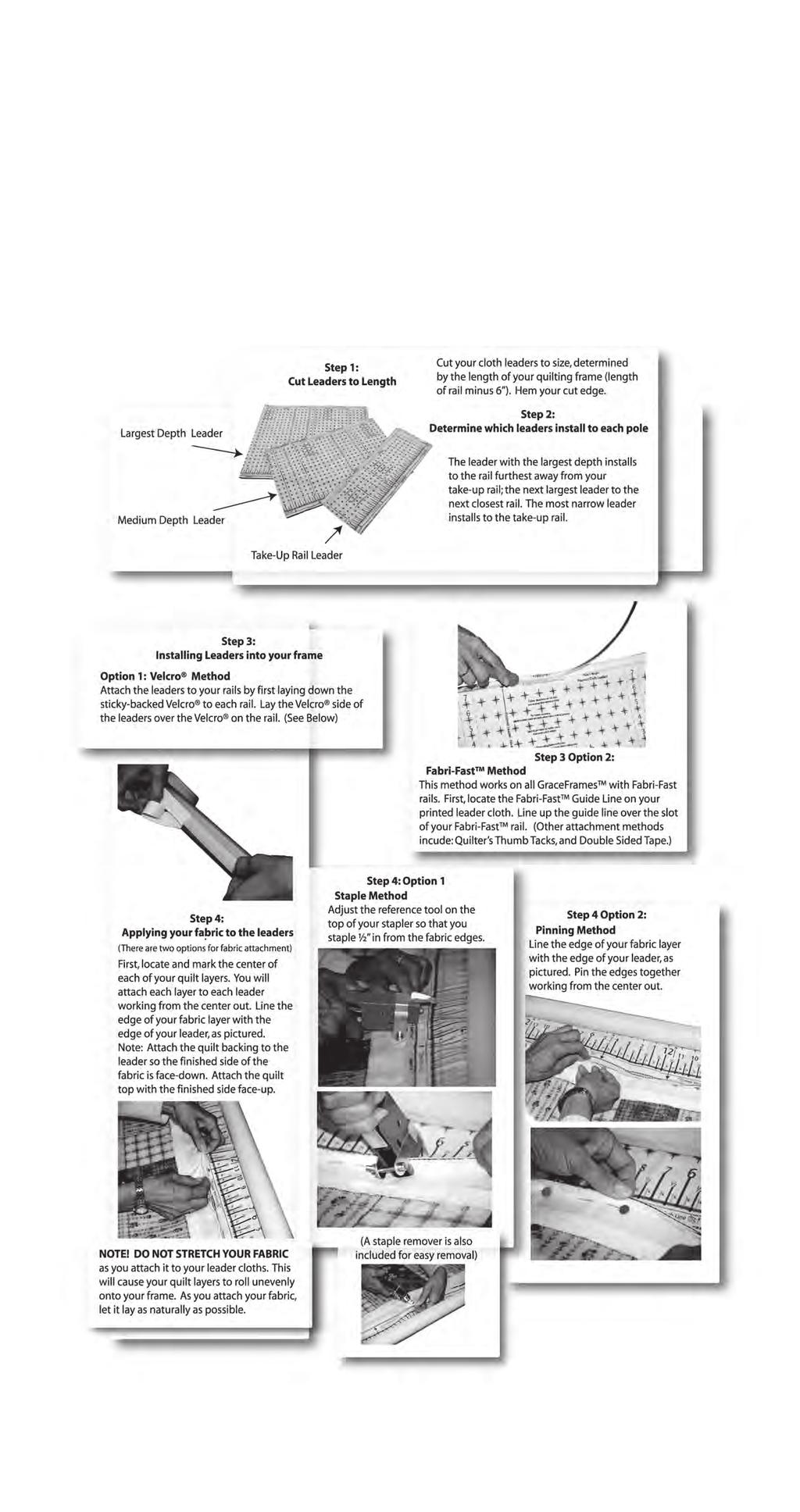
15 Fabric Installation: Using leader cloths enable you to finish your quilt completely, end to the end, without having to take your quilt off the frame. Fabric Installation Overview 3rd rail 2nd rail take up leader top fabric (Step 1) backing (Step 2) Step 1: Install quilt top to 2nd rail and roll up. Step 2: Install quilt backing to the 3rd rail and roll up. Step 3: Install batting to the 4th rail and roll up. Step 4: Attach quilt backing to take up rail. Step 5: Attach batting to take up rail. Step 6: Attach quilt top to take up rail. 1st rail (take up rail) 3rd rail 2nd rail 1st rail 4th rail batting top fabric backing Fig. FI-1 batting (Step 3) 4th rail Fig. FI-2 Leader Cloth Installation Instructions Preview Step L1: Draw a straight line all the way across each of your fabric rails with a black magic marker. Step L2: Mark the center of each cloth leader on both edges (Length-wise). Also place a mark at the center of each of the fabric rails. Always measure to the center of the rails from the same end of the quilting frame. Draw the lines at the center of each rail so that they cross the lines previously drawn across the rails. Step L3: Now you need to attach your leaders to their respective rails. The fabric can easily be attached to the rails by applying a piece of adhesive backed hook Velcro along the lines that you have drawn down each fabric rail. backing leader 15 2nd 3rd 4th Fig. FI-3 top fabric leader 1st take up leader Note: This illustration shows the cloth leaders installed on each rail prior to your quilt layers being installed.
16 Installing Fabric Layers Onto Rails STEP 1: Quilt Top To 2nd Rail Step 1-1: Determine which will be the front and back edges of your quilt. Step 1-2: Line up the center of your fabric layer with the center of the cloth leader on the 2nd Rail. Pin the back edge of your top to the leader cloth. This is to be done with the finished side of the fabric facing up. 3rd take up leader top fabric 1st 2nd backing batting Step 1-3: Do not stretch or pull the fabric during this process. Let it lay as naturally as possible. Step 1-4: Roll your leader and top onto the 2nd rail completely. Again, be sure the fabrics stay lined up. Smooth out any wrinkles as you roll by brushing the fabric from the center out, being very careful not to stretch or pull the fabric excessively. NOTE! It is important that you roll the rail the proper direction so the fabric rolls onto the 2nd rail the right way (when fabric rolls off the rail toward the take-up rail, it should roll under and off the rail. See Fig. FI-4). STEP 2: Quilt Backing To 3rd Rail Fig. FI-4 2nd 3rd 4th top fabric 1st Step 2-1: To begin, determine which will be the front and back edges of your quilt backing (make sure the backing is not wider than your quilting frame). Note: If your backing is made up of more than one piece of fabric, cut your selvedges off and flatten them out to allow the backing the proper give it needs. Fig. FI-5 2nd 4th 1st Step 2-2: Line up the center of your fabric layer with the center of the cloth leader on the 3rd rail. Pin the back edge of your backing to the leader cloth. This is to be done with the finished side of the fabric facing down. Note: Do not stretch or pull the fabric during this process, let it lay as naturally as possible. 3rd batting Step 2-3: Roll your leader and backing onto the 3rd rail completely. Watch to make sure the fabric stays lined up. Smooth out any wrinkles as you roll by brushing the fabric from the center out. However, be very careful not to stretch or pull the fabric excessively. Note: It is important that you roll the rail the proper direction so the fabric rolls over and onto the 3rd rail (Fig. FI-4). 16 Fig. FI-6 4th
17 STEP 3: Batting Step 3-1: A light, bonded batting is recommended. Step 3-2: Center the batting on the 4th rail. Roll the batting onto the 4th rail, being sure to roll the proper direction so that it, like the quilt top, comes off the rail from the bottom when unrolling. STEP 4: Attaching Your Quilt Layers To The Take-Up Rail Step 4-1: Take the edge of the quilt backing and pin it along the straight line of the take up rail leader in a smooth manner, without stretching your fabric. backing 3rd batting quilt top 1st 2nd 4th Fig. FI-7 Step 4-2: Next, bring your batting up in between the 3rd rail and 2nd rail and drape over the backing. Lay it along the pin line of your backing on the take up rail cloth leader. Step 4-3: Finally, bring the quilt top up over the backing and batting and lay it over the batting along the pin line on the take up rail cloth leader. Pin your top and batting along the same line as your backing so that it is smooth. Rolling Your Fabric When you have completed your work area and are ready to move to the next, simply release the ratchet stops on the 2nd and 3rd rails, allowing them to roll freely. Then, roll the 1st rail forward, rolling the completed work area onto that rail. TIP! As you roll forward, the quilt will accumulate on the 1st rail. Be sure to raise the take up rail brackets slightly as needed, so that the bottom of the rolled up fabric stays about 1/8 above the throat plate of your sewing machine base. Failing to do so will cause your carriage assembly to roll less smoothly. Bungee Clamp Installation There are four Bungee Clamps provided with your Quilting Frame. The Bungee Clamps allow you to easily add side tension to your quilt fabric. Clip your bungee Clamps to the quilt fabric, then insert the loose end of the Bungee Cord through the Bungee Tube and pull it to the side Bungee Stop on to lock it into place, as shown in Fig. BC1-1. Fabric Bungee Clamp Bungee Bar Bungee Cord Fig. BC1-1 Cord Stop 17
18 18
Depending on the size you ordered you will have either 5 Foot sections which will build the 10 Foot frame or 6 Foot sections which will build the 12
 XL Quilting Frame 1 Depending on the size you ordered you will have either 5 Foot sections which will build the 10 Foot frame or 6 Foot sections which will build the 12 Foot frame Printed 2 June 2014 Updated
The Queen Quilter Professional Quilters Kit Frame
 The Queen Quilter Professional Quilters Kit Frame Assembly Instructions Table of Contents: Before you begin......................... Pg. 2 Wood parts............................. Pg. 3 Hardware..............................
Continuum Frame Assembly Instructions
 Continuum Frame Assembly Instructions Copyright January 1, 2017 Jim M. Bagley, GraceWood, Inc (Reproduction Prohibited) Version 2.2 Table of Contents Continuum Frame Table of Contents... i Warranty...ii
Machine Quilting Frame assembly, and instruction manual
 Machine Quilting Frame assembly, and instruction manual Table of Contents Parts List................. Pg. 2 Step 1 - Legs............... Pg. 4 Step 2 - Lower Leg Brace....... Pg. 5 Step 3 - Frame Ends..........
The Mini Pinni Quilting Frame
 The Mini Pinni Quilting Frame Copyright September 2007 Jim M. Bagley, GraceWood, Inc (Reproduction Prohibited) Print Date 10-16-07 1 The Mini Pinni Quilting Frame By The Grace Company Part List Parts List
Assembly Instructions. Copyright May 01, 2013 Jim M. Bagley, GraceWood, Inc (Reproduction Prohibited)
") Assembly Instructions Copyright May 01, 2013 Jim M. Bagley, GraceWood, Inc (Reproduction Prohibited) Table of Contents Part List Part List... 3 Assembly Steps Step 1-Foot Assembly... 5 Step 2-Leg Assembly...
Assembly Instructions Copyright May 01, 2013 Jim M. Bagley, GraceWood, Inc (Reproduction Prohibited) Table of Contents Part List Part List... 3 Assembly Steps Step 1-Foot Assembly... 5 Step 2-Leg Assembly...
Q-Zone Hoop-Frame. Assembly Instructions. Copyright July 11, 2018 Grace Company (Reproduction Prohibited) Version 1.8
 Version 1.8") Q-Zone Hoop-Frame Assembly Instructions Copyright July 11, 2018 Grace Company (Reproduction Prohibited) Version 1.8 Table of Contents Table of Contents... i Warranty... ii Parts List Box 1...iii Box 2...
Q-Zone Hoop-Frame Assembly Instructions Copyright July 11, 2018 Grace Company (Reproduction Prohibited) Version 1.8 Table of Contents Table of Contents... i Warranty... ii Parts List Box 1...iii Box 2...
Juki Quilting Frame. Assembly and Use Instruction Manual. Max Overall Dimensions: Length Crib: King: Tall: Wide: 42
 Juki Quilting Frame Assembly and Use Instruction Manual Max Overall Dimensions: Length Crib: 63 1 4 King: 128 1 4 Tall: 45 3 4-51 3 4 Wide: 42 Copyright January, 2015 Version 9.6 (Page 1) Contents Parts
Dream Fabric Frame Assembly Instructions
 Dream Fabric Frame Assembly Instructions Copyright May 01, 2015 Jim M. Bagley, GraceWood, Inc (Reproduction Prohibited) Version 1 Table Of Contents Parts List 3 Step 1: Table Set Up 6 Step 2: Install the
HQ Studio2 Frame. Assembly Instructions. Table of Contents. What s Included
 HQ Studio2 Frame Assembly Instructions UPDATED NOVEMBER 2017 Table of Contents Parts List... page 2 Hardware List.... page 3 HQ Studio Frame Box Contents...page 4 Step 1- Frame Side Assembly... page 5
HQ Studio2 Frame. Assembly Instructions. Table of Contents. What s Included
 HQ Studio2 Frame Assembly Instructions UPDATED June 2018 Table of Contents Parts List... page 2 Hardware List.... page 3 HQ Studio Frame Box Contents...page 4 Step 1: Frame Side Assembly... page 5 Step
Dream Fabric Frame Assembly Instructions
 Dream Fabric Frame Assembly Instructions Copyright January 1, 2016 Jim M. Bagley, GraceWood, Inc (Reproduction Prohibited) Version 2.4 Table Of Contents Parts List 3 Step 1: Table Set Up 6 Step 2: Install
THE GRACE EZ3 FABRI-FAST QUILTING FRAME
 THE GRACE EZ3 FABRI-FAST QUILTING FRAME TABLE OF CONTENTS CARE, FINISHING AND STORAGE..................................................... 2 WARRANTY..........................................................................
TABLE OF CONTENTS CARE, FINISHING AND STORAGE... WARRANTY... PARTS LIST... ASSEMBLY STEPS STEP 1: LAMPHOLDER TO POLE MOUNT END ASSEMBLY...
 TABLE OF CONTENTS CARE, FINISHING AND STORAGE................................................ WARRANTY................................................................. PARTS LIST.................................................................
for HQ 18 Avanté HQ Studio Frame
 HQ Studio Frame for HQ 18 Avanté Assembly Instructions Table of Contents Parts List page 2 Hardware List page 3 HQ Studio Frame Box Contents page 4 Step 1- Frame Side Assembly page 5 Step 2- Table Assembly
HQ Pole Upgrade Kit for HQ Adjustable Table and HQ QuilTable Assembly Instructions 1
 HQ Pole Upgrade Kit for HQ Adjustable Table and HQ QuilTable Assembly Instructions QF09775 The pole upgrade kit can be used with or without the QF09700 HQ Precison-Glide track upgrade kit. What s Included
Equipped with the Professional Series Rails Table of Contents. Care, Finishing and Storage Quilting Instructions and Tips... Trouble Shooting...
 Z44 Fabri-Fast Edition Hand Quilting Frame Equipped with the Professional Series Rails Table of Contents Care, Finishing and Storage............................................ 2 Warranty.........................................................
MACHINE QUILTING FRAME
 MACHINE QUILTING FRAME YOU WILL NEED TO PURCHASE: 5 pieces of 1-1/4 thin wall metal conduit (EMT) cut to your preferred length for the rollers. (Maximum 120 ) DETERMINING YOUR ROLLER LENGTH: Determine
The Sturdy-Lite. Copyright December 2005 Jim M. Bagley, GraceWood, Inc (Reproduction Prohibited)
") The Sturdy-Lite Parts List Wood Parts List... 2 Hardware Parts List... 3 Care of Your Frame... 4 Assembly Steps: Step 1: Table Brace Assembly... 6 Step 2: Frame End Assembly... 6 Step 3: Leg to Frame Assembly...
The Sturdy-Lite Parts List Wood Parts List... 2 Hardware Parts List... 3 Care of Your Frame... 4 Assembly Steps: Step 1: Table Brace Assembly... 6 Step 2: Frame End Assembly... 6 Step 3: Leg to Frame Assembly...
GMQ 16 Adapter Set Assembly Instructions Copyright November, 2003 GraceWood, Inc. Table of Contents
 GMQ 16 Adapter Set Assembly Instructions Copyright November, 2003 GraceWood, Inc. Table of Contents Parts List.................................................................. 1 Assembly Instructions.......................................................3
Quilting with The GraceHoop 2 TM
 Quilting with The GraceHoop 2 TM T h e G r a c e H o o p Squared Table of Contents Customer Service Information............................. 2 Care, Finishing and Storage...............................
Hardware and Components:
 Hardware and Components: (A) 5/16 x 2 Hex Bolt (B) 5/16 x 2-1/4 Hex Bolt (C) 5/16 x 2-1/2 Hex Bolt (D) 4X 5/16 x 3/4 Hex Bolt (E) 4X 5/16 x 1-1/4 Hex Bolt (F) 11X 5/16 Flat Washer (G) 12X 5/16 Nylock Nut
TABLE OF CONTENTS COPYRIGHT MAY 2003 REPRODUCTION PROHIBITED JIM M. BAGLEY GRACEWOOD, INC. PATENT PENDING
 TABLE OF CONTENTS CARE, FINISHING AND STORAGE................................................ 2 WARRANTY.................................................................. 2 PARTS LIST.................................................................
ABM International, Inc. Navigator Assembly Manual
 ABM International, Inc. 1 1.0: Parts List Tablet (Qty. 1) Tablet mount (Qty. 1) NOTE: Mount may appear and operate different then image below Control Box (Qty. 1) Motor Power Supply (Qty. 1) 2 X-axis motor
HQ Gallery Frame. Assembly Instructions QM HQ Gallery Frame Box Contents
 HQ Gallery Frame Assembly Instructions QM31301 HQ Gallery Frame Box Contents Box # Parts (See pages 2 and 3 for descriptions and quantities) 1 Table sections, items listed in What s Included below 2 End
HQ Precision-Glide Track Upgrade 2 Extension Kit for HQ Studio Frame Part# QF09750
 HQ Precision-Glide Track Upgrade 2 Extension Kit for HQ Studio Frame Part# QF09750 Important Note: Upgrading the track system on the HQ Studio Frame requires the use of this 2 Extension Kit (Part #QF09750),
Assembly Instructions. Table of Contents
 HQ Little Foot Assembly Instructions Back of Handi Quilter, Inc. 501 North 400 West North Salt Lake, UT 84054 1-877-697-8458 Front of 2015 Handi Quilter, Inc. www.handiquilter.com Printed in the United
For additional assistance call
 The following pages will help guide you through the process of assembling your new 48 custom prize wheel. Choose an assembly area with plenty of room to lay your pieces on the floor and also a bench or
INSTALLATION INSTRUCTIONS
 Do not attempt to install this product on any vehicle other than the one it is designed for and listed above! Parts List 10 3/8 X 1 1/4 Hex Bolt 10 3/8 Lock Washer 4 3/8 Hex Nut 4 3/8 Flat Washer 2 3169)
Hardware and Components:
 Hardware and Components: (A) 4X 5/16 x 1 Carriage Bolt (B) 2X 5/16 x 2-1/4 Carriage Bolt (C) 2X 5/16 x 3-1/4 Hex Bolt (D) 2X 5/16 x 3/4 Hex Bolt (E) 2X 5/16 x 1-1/4 Hex Bolt (F) 5/16 x 2-1/4 Hex Bolt (G)
The Grace Z44 TM New Millennium Quilting System
 The Grace Z44 TM New Millennium Quilting System Table of Contents Care, Finishing and Storage......................................x Warranty....................................................x Parts
HQ Gallery Frame. Assembly Instructions QM HQ Gallery Frame Box Contents
 HQ Gallery Frame Assembly Instructions QM31301 HQ Gallery Frame Box Contents Box # Parts (See pages 2 and 3 for descriptions and quantities) 1 Table sections, items listed in What s Included below 2 End
User Instructions Multiline Otter Scoreboard Caddy Assembly
 List of parts: User Instructions Multiline Otter Scoreboard Caddy Assembly Single Caddy Double Caddy 1 1 Base assembly with attached wheels 2 4 1 1 2 4 4 8 10 20 12 Uprights (60 or 74 aluminum extrusion)
This manual will aid in the assembly of the FireBall V90 and FireBall X90. The assembly of both machines will be identical, unless specified.
 This manual will aid in the assembly of the FireBall V90 and FireBall X90. The assembly of both machines will be identical, unless specified. Step #1 Lay all parts out to verify quantities. (2) 2 x 25-1/4
HQ Studio Frame Two-Foot Section Assembly Instructions From Twelve-Foot to Ten-Foot
 HQ Studio Frame Two-Foot Section Assembly Instructions From Twelve-Foot to Ten-Foot HQ Studio Frame Two-Foot Includes: Includes one (1) two-foot table frame with plastic top, two (2) two-foot track supports,
earl Pearl Frame Instruction Addendum How to Load Fabric to Frame Model BLQF Model BLQF
 earl Pearl Frame Instruction Addendum How to Load Fabric to Frame Model BLQF Model BLQF www.babylock.com Step 1 Anatomy of the Frame Note: A little preparation the first time you use your quilting frame
HQ 24 Fusion Frame Assembly 1
 HQ 24 Fusion Frame Assembly Instructions HQ 24 Fusion Frame Box Contents Box # Parts (See pages 2 & 3 for descriptions and quantities) 1 Table sections, items listed in What s Included below 2 End leg
BABY WOLF LOOM. Assembly Instructions for Knocked-Down Looms
 BABY WOLF LOOM Assembly Instructions for Knocked-Down Looms BEFORE YOU BEGIN Please read through the directions before beginning to assemble your loom. Unpack the loom parts carefully. Do not throw away
Strata. urniture. Adriana Instructions. Parts in the Arm Box: Parts in the Body Box: Watch our assembly videos at
 1A Watch our assembly videos at www.strataf.com/videos Parts in the Arm Box: Arm - Outside View Arm - Inside View 1B Parts in the Body Box: Back Deck x 1 Seat Deck x 1 with the Feet attached Back Panel
ClearSpan Twist-of-the-Wrist Assembly Instructions
 ClearSpan Twist-of-the-Wrist Assembly Instructions Curved-Wall for Roll-Up Side Flat-Wall for Curtain Application 2008 ClearSpan All Rights Reserved. Reproduction is prohibited without permission. Revision
Roll In W/L Dock PAGE 1
 Roll In W/L Dock PAGE 1 1 2 3/8 X 1 CARRIAGE BOLT SS 3/8 FLANGE NUT BRASS 3 4 1/2-13 X 1.25 SQ BOLT SS 1/2 SQ NUT BRASS 5 3/8-16 X 2.5" BOLT SS PAGE 2 6 7 BRACE BRKT SINGLE AXLE TUBE 8 9 3" AXLE WASHER
RIPPER PEDAL. Bearing / Axle Replacement. ( Disassembly )
") RIPPER PEDAL Bearing / Axle Replacement ( Disassembly ) 1 1. Use good quality tools to avoid stripping screw sockets. 2. When servicing your pedals, work on one side at a time to prevent parts from mixing
RIPPER PEDAL Bearing / Axle Replacement ( Disassembly ) 1 1. Use good quality tools to avoid stripping screw sockets. 2. When servicing your pedals, work on one side at a time to prevent parts from mixing
FlexFrame - Storage Components and Skins
 FlexFrame - Storage Components and Skins 1/4 Square Drive Ball-Point Hex-Bit Socket 1/8 Short Hex, 1-1/2 Overall Length McMaster Part # 54075A44 Table of Contents Topic Page Storage Components 2 General
WOLF PUP LOOM TM & WOLF PUP LT LOOM TM
 WOLF PUP LOOM TM & WOLF PUP LT LOOM TM Assembly Instructions FL3000 FL3006 FL3009 WOLF PUP WOLF PUP LT Find out more at schachtspindle.com Schacht Spindle Company 6101 Ben Place Boulder, CO 80301 p. 303.442.3212
This guide contains everything you need to set up and operate all three. Inspira Imperial Quilting Frame Assembly...2
 Congratulations on the purchase of your Husqvarna Viking Mega Quilter 18x8, Inspira Imperial Quilting Frame, and QBOT by Inspira! This guide contains everything you need to set up and operate all three.
Replacing the Reciprocator on the SWF Compact Series Machine (601C and 1201C)
") Follow the instructions below to replace the reciprocator in the SWF Compact series machines. The tools required can be found in the tool kit that came with the machine. Preparation 1. First, place the
Follow the instructions below to replace the reciprocator in the SWF Compact series machines. The tools required can be found in the tool kit that came with the machine. Preparation 1. First, place the
Installation Instructions - Model V4JSD 1
 Installation Instructions - Model V4JSD 1 Support Assemblies: Parts list: (Note see enclosed cut sheet for quantities and dimensional information) A vertical structural member (1 ½ x 1 ½ modular frame)
USSC LLC 4 ONE LLC FIELD MODIFICATION INSTRUCTIONS
 1 OF 17 A 1. PURPOSE: Instructions for in field replacement of 9004 mechanical suspension top pan 2. SCOPE: 9004 mechanical suspension with legacy two point LX back frame and current LX back frame 3. PROCEDURE:
Quilting with the NEW Grace A34 TM Quilting Frame
 Quilting with the NEW Grace A34 TM Quilting Frame Table of Contents Care of your Grace Frame... 2 Correspondence and Technical Support... 2 Warranty information... 2 Parts Lists... 3-4 Assembly Leg and
CV1B Sliding Table Installation and Setup Guide
 CV1B Sliding Table Installation and Setup Guide Tech Mark, Inc 7901 Industry Drive North Little Rock, AR 72117 tel (501) 945-9393 fax (501) 945-0312 www.tech-mark.com email: info@tech-mark.com The CV1B
Fortress Fe Posts must always be secured to the deck framing. Fortress Fe Posts should never be attached to only the deck boards.
 Installation Instructions for Fortress Horizontal Cable Panel System with UB-05 Brackets and Fe Posts It is the responsibility of the installer to meet all code and safety requirements, and to obtain all
Heavy-Duty Bypass Track System
 Heavy-Duty Bypass Track System Please Note: This track system must be installed with the screws going into a solid surface such as studs or a header. Due to the spacing of the holes on these Brackets,
S48-L12-SC AND G48-L12-GC STEEL PORTA-DOCK S82 SC 6 X 12 PLATFORM AND G82 GC 6 X 12 PLATFORM
 PAGE 1 OF 6 PORTA-DOCK, INC. S48-L12-SC AND G48-L12-GC STEEL PORTA-DOCK S82 SC 6 X 12 PLATFORM AND G82 GC 6 X 12 PLATFORM Thank you for purchasing our product! *Please read these instructions and follow
CONTENTS TOOL LIST U P S I D E I N N O V A T I O N S, L L C RAMP AND STEP SYSTEM ASSEMBLY INSTRUCTIONS. Revised: June 2013
 U P S I D E I N N O V A T I O N S, L L C RAMP AND STEP SYSTEM ASSEMBLY INSTRUCTIONS TOOL LIST Required Tools: - Reciprocating Saw with Metal Cutting Blade - Drill - 7/16 Drill Bit for Metal Drilling -
M2 Assembly. M2 Sub-Assemblies mm Belt Sub-Assembly mm Belt Sub-Assembly Spider Sub-Assembly... 4
 M2 Assembly Table of Contents M2 Sub-Assemblies... 3 630mm Belt Sub-Assembly... 3 702mm Belt Sub-Assembly... 3 Spider Sub-Assembly... 4 Idler Bolt Sub-Assembly... 8 Y Motor Sub-Assembly... 9 X Motor Sub-Assembly...
Thank you for purchasing out product! *Please read these instructions and follow them step by step. *
 Page 1 of 7 AD17 AA DS 4 X 16 T12 Thank you for purchasing out product! *Please read these instructions and follow them step by step. * STEP 1. Slide two support posts (REF. # 24) into the two outside
MobileTrak5 Installation Instructions
 MobileTrak5 Installation Instructions PLEASE OPEN ALL BOXES & CHECK TO MAKE SURE YOU HAVE ALL PIECES REQUIRED READ ALL INSTRUCTIONS BEFORE STARTING Tools Required for Assembly 7/16, 1/2 Wrench Phillips
MODEL T28173/T28174 ROLLER TABLES INSTRUCTIONS
 MODEL T28173/T28174 ROLLER TABLES INSTRUCTIONS FOR MODELS MFD. SINCE 10/17 For questions or help with this product contact Tech Support at (570) 546-9663 or techsupport@grizzly.com Rails Rollers Reversible
Flat Panel Stand FPZ-655. for 32" to 55" Flat Panel Screens FEATURES. Reinforced universal adapter plate for a strong hold
 FPZ-655 Flat Panel Stand for 32" to 55" Flat Panel Screens For a viewing experience that really stands out, Peerless FPZ-655 Universal Flat Panel Stand for 32" 55" flat panel TVs provides a brilliant combination
INSTALLATION LS MODEL
 INSTALLATION LS MODEL Page 2 TABLE OF CONTENTS Section 1: Included parts... pg 4 Section 2: Installing the Shirley Stitcher II on Quilt Frame.. pg 5 Section 3: Connecting Shirley Stitcher II to Tin Lizzie
AUTOMATIC ADVANCE MANUAL
 AUTOMATIC ADVANCE MANUAL AVL Looms, Inc. 3851 Morrow Lane, Suite #9 Chico, CA 95928-8305 530 893-4915 530 893-1372 fax # info@avlusa.com www.avlusa.com Copyright 2009 TABLE OF CONTENTS Page # I. Parts.........................
Odyssey Elementary Stem Installation
 Tools Needed Grease Allen Wrenches Open/Closed end wrench Adjustable wrench Note: Tools needed will vary depending on the style of headset compression cap and bolt being used. Removing the Handlebars Loosen
BLADE N BULLET BLIND Cabela s Item Number:
 BLADE N BULLET BLIND Cabela s Item Number: 466353 Visit cabelas.com or call 1-800-237-4444 for assistance. TABLE OF CONTENTS 2 3 4-13 Table of Contents Package Contents Instructions for Use Visit cabelas.com
 For Wallbed models: KING SIZE INSTRUCTION BOOKLET #C1 Watch step by step installation instructions at: https://www.wallbedsbywilding.com/wallbed-installation-studio-series/ WARNING! ALL MURPHY/WALLBED
HONDA RIDGELINE (KIT #601) Installation Instructions (to be used in addition to owners manual)
 Installation Instructions (to be used in addition to owners manual)") HONDA RIDGELINE (KIT #601) Installation Instructions (to be used in addition to owners manual) IMPORTANT NOTE: Read before beginning installation. These instructions replace all of Step 1 of the instructions
HONDA RIDGELINE (KIT #601) Installation Instructions (to be used in addition to owners manual) IMPORTANT NOTE: Read before beginning installation. These instructions replace all of Step 1 of the instructions
Basic steps to time the Gammill quilting machine s rotary sewing hook
 Basic steps to time the Gammill quilting machine s rotary sewing hook 1.) Turn the machine off and unplug it. 2.) With the needle bar in the raised position, remove the bobbin and bobbin case. 3.) Remove
PORTA-DOCK, INC. AP17 APD DS 4 X 16 T12 AW17 CPD DS 4 X 16 T12
 Page 1 of 7 PORTA-DOCK, INC. AP17 APD DS 4 X 16 T12 AW17 CPD DS 4 X 16 T12 *For Beige Decking Add the Letter B to Model* Thank you for purchasing out product! *Please read these instructions and follow
INSTALLATION INSTRUCTIONS for the JOMY RETRACTABLE LADDER. If there are any questions, please call (800)
") INSTALLATION INSTRUCTIONS for the JOMY RETRACTABLE LADDER If there are any questions, please call (800) 255-2591 INSTALLATION INSTRUCTIONS WARNING! Ladder Sections Lock When Closed. Do Not Install or Close
INSTALLATION INSTRUCTIONS for the JOMY RETRACTABLE LADDER If there are any questions, please call (800) 255-2591 INSTALLATION INSTRUCTIONS WARNING! Ladder Sections Lock When Closed. Do Not Install or Close
Legacy Woodworking Machinery a division of Phantom Engineering. The Legacy CNC. Assembly Manual
 Legacy Woodworking Machinery a division of Phantom Engineering The Legacy CNC Assembly Manual New Orientation of the Legacy Step one: Re-orientation of the machine Remove the X-axis screw and supports.
VIDEO MOUNT PRODUCTS. Instruction Sheet For: PMC-S
 Instruction Sheet For: ITEM NO. 1 DESCRIPTION Lower Cage QTY. 1 2 Top Panel 1 3 Security Bar 2 4 Security Screw M6*P1.0*L12 14 5 6 Washer 6.4* 18*T1.6 Nylon Nut M6*P1.0 4 4 7 Allen Key 1 7 4 2 5 6 1 3
INSTALLATION INSTRUCTIONS
 INSTALLATION INSTRUCTIONS Furniture Solutions: 68 Shipstation with Storage Shelf Model Numbers: PB001 (D9001, D9010N, D9021, D9030, D9032/D9033, D9098, RC4054) Introduction This document provides the Pitney
Passage 4 Bike Hitch Rack
 Thank you for purchasing the XPORT Passage 4 Bike Hitch rack. This rack will securely carry up to 4 bicycles. The trigger and lift assist mechanisms allow the rack to tilt up or down allowing easy access
OPERATOR'S MANUAL 46" SNOW BLADE. Model Numbers OEM IMPORTANT: READ SAFETY RULES AND INSTRUCTIONS CAREFULLY
 OPERATOR'S MANUAL 46" SNOW BLADE Model Numbers 190-833-OEM IMPORTANT: READ SAFETY RULES AND INSTRUCTIONS CAREFULLY MTD PRODUCTS INC. P.O. BOX 368022 CLEVELAND, OHIO 44136-9722 PRINTED IN U.S.A. FORM NO.
Classic Roll Tarp. Installation Instructions. Attention Dealers: Please give this owners manual to the customer when the product is delivered.
 Serving the Truck & Trailer Industry Since 1944 Classic Roll Tarp Attention Dealers: Please give this owners manual to the customer when the product is delivered. Call 800-535-9545 www.aeroindustries.com
https://www.wallbedsbywilding.com/wallbed-installation-studio-series/
 For Wallbed models: KING SIZE INSTRUCTION BOOKLET #C1 Watch step by step installation instructions at: https://www.wallbedsbywilding.com/wallbed-installation-studio-series/ WARNING! ALL MURPHY/WALLBED
Gared Pro-S Portable Backstop
 Models: 9616 & 9618 Installation, Operation and Maintenance Instructions Please read all instructions before attempting installation or operation of these units SAVE THESE INSTRUCTIONS FOR FUTURE USE PUBLICATION
BEAST THE. Tube and Pipe Notcher Operating Instructions. Notches In Bends Straight Notches. Angled Notches. Offset Notches
 Copyright (c) 2007 J D SQUARED INC. www.jd2.com THE BEAST Tube and Pipe Notcher Operating Instructions Notches In Bends Straight Notches Angled Notches PATENT PENDING Offset Notches Assembly After unpacking
O-Sullivan King 4 Poster Bed O-Sullivan Queen 4 Poster Bed Parts and Hardware List
 Parts and Hardware List A. Left Headboard Post 1 pc B. Right Headboard Post 1 pc C. Left Footboard Post 1 pc D. Right Footboard Post 1 pc E. Headboard Panel 1 pc F. Footboard Rail 1 pc. Spindles 4 pcs
INSTRUCTION BOOKLET #34. For Wallbed models: KING SIZE SIERRA WITH STORAGE HEADBOARD
 For Wallbed models: KING SIZE SIERRA WITH STORAGE HEADBOARD INSTRUCTION BOOKLET #34 WARNING! ALL MURPHY/WALLBED SYSTEMS CONTAIN STORED ENERGY. FAILURE TO USE AND FOLLOW THESE INSTRUCTIONS DURING THE INSTALLATION
Installation and Assembly: 32" - 60" Flat Panel TV Cart
 nstallation and Assembly: 32" - 60" Flat Panel TV Cart Models: SR1M, SR560M R This product is UL Listed. t must be installed by a qualified professional installer. Max UL Load Capacity: 150 lb (68 kg)
ClearSpan End Frame Kit 26' Wide x 12' High
 ClearSpan End Frame Kit 26' Wide x 12' High Diagram shows the end frame kit for an end wall without a door. (Door and end panel are purchased separately.) Rafter and struts shown in the above diagram are
 INSTRUCTION BOOKLET #C0 Watch step by step installation instructions at: https://www.wallbedsbywilding.com/wallbed-installation-studio-series/ WARNING! ALL MURPHY/WALLBED SYSTEMS CONTAIN STORED ENERGY.
Kwik-Lock. Installation Instructions. Attention Dealers: Please give this owners manual to the customer when the product is delivered.
 Serving the Truck & Trailer Industry Since 1944 Installation Instructions Attention Dealers: Please give this owners manual to the customer when the product is delivered. Call 800-535-9545 www.aeroindustries.com
Electric Skein Winder
 Electric Skein Winder Assembly and Use Package Contents 1 - Triangular Body (w/ motor) 1 - Cross Arm 1 - Left Foot (w/ yarn guide) 1 - Right Foot 1 - Adjustable Finger (w/ yarn clip) 3 - Adjustable Fingers
southpaw enterprises, inc.
 southpaw enterprises, inc. Instruction Sheet C-STAND 7100 Store these instructions in a safe place or with the enclosed maintenance checklist Take time to familiarize yourself with the use and maintenance
ABM International, Inc.
 ABM International, Inc. Lightning Stitch required 1 1.0: Parts List head and motor assembly (Qty. 1) Reel stand (Qty. 1) Needle bar frame clamp (Qty. 1) Motor drive (Qty. 1) 2 Cable harness with bracket
PRS Retro Z-Axis Installation
 PRS Retro Z-Axis Installation Page -1- PRS Retro Z-Axis Installation This document is a guide to installing the PRS Retro Z-axis on early ShopBot models. It describes installation for PR models with PK299
 INSTRUCTION BOOKLET #C10 Watch step by step installation instructions at: https://www.wallbedsbywilding.com/wallbed-installation-studio-series/ WARNING! ALL MURPHY/WALLBED SYSTEMS CONTAIN STORED ENERGY.
A59 APD & A86 CPD 5'X 16' SW ALUMINUM PORTA-DOCK
 Page 1 of 5 PORTA-DOCK, INC. A59 APD & A86 CPD 5'X 16' SW ALUMINUM PORTA-DOCK *For Beige Decking Add the Letter B to model* Thank you for purchasing our product! *Please read these instructions and follow
SAFETY INSTRUCTIONS. Wear protective clothing, including safety glasses and steel toe boots.
 SAFETY INSTRUCTIONS Wear protective clothing, including safety glasses and steel toe boots. DO NOT allow loose clothing or long hair near machine operations. Keep work site and machine clean. Use brush
INVENT3D Printer Kit Disassembly Instructions
 INVENT3D Printer Kit Disassembly Instructions Version 6 AST2 10/26/16 1 I. General Disassembly Instructions Use the case layer drawings to ensure that components are stored in the appropriate location
N. 15th Street, Middlesboro, KY FLIP TARP DUMP BODY INSTALLATION INSTRUCTIONS
 1-800-248-7717 1002 N. 15th Street, Middlesboro, KY 40965 FLIP TARP DUMP BODY INSTALLATION INSTRUCTIONS Congratulations on your purchase of a Mountain Flip Tarp Dump Body tarping system. With tarping systems
The Bowflex Revolution XP Home Gym Assembly Instructions. P/N: Rev ( /0 )
") P/N: 001-7057 Rev ( /0 ) The Bowflex Revolution XP Home Gym Assembly Instructions 2 Table of Contents Before You Start... 2 Tools You Will Need / Hardware Contents... 3 Box Contents... 6 Assembling Your
P/N: 001-7057 Rev ( /0 ) The Bowflex Revolution XP Home Gym Assembly Instructions 2 Table of Contents Before You Start... 2 Tools You Will Need / Hardware Contents... 3 Box Contents... 6 Assembling Your
INSTRUCTION BOOKLET #C21. For Wallbed models: KING SIZE
 For Wallbed models: KING SIZE INSTRUCTION BOOKLET #C1 WARNING! ALL MURPHY/WALLBED SYSTEMS CONTAIN STORED ENERGY. FAILURE TO USE AND FOLLOW THESE INSTRUCTIONS DURING THE INSTALLATION PROCESS COULD RESULT
INSTRUCTION BOOKLET #C20
 INSTRUCTION BOOKLET #C0 WARNING! ALL MURPHY/WALLBED SYSTEMS CONTAIN STORED ENERGY. FAILURE TO USE AND FOLLOW THESE INSTRUCTIONS DURING THE INSTALLATION PROCESS COULD RESULT IN SEVERE PERSONAL INJURY TO
400A 40113V, 401A 40120V, & 401AL 40120VL ALUMINUM VERTICAL 4000 LB LIFT INCLUDES SCREW LEG ASSEMBLY INSTRUCTIONS
 12/11/07 PAGE 1 OF 12 400A 40113V, 401A 40120V, & 401AL 40120VL ALUMINUM VERTICAL 4000 LB LIFT INCLUDES SCREW LEG ASSEMBLY INSTRUCTIONS Thank you for purchasing our product! *Please read these instructions
WOLF LOOM DOUBLE BACK BEAM
 WOLF LOOM DOUBLE BACK BEAM Assembly Instructions Find out more at schachtspindle.com Schacht Spindle Company 6101 Ben Place Boulder, CO 80301 p. 303.442.3212 f. 303.447.9273 2017 Schacht Spindle Company,
Calf-Tel Pen System Assembly Instructions
 Calf-Tel Pen System Assembly Instructions (Instructions work for 4, 6, and the 7 Pen Systems) 1 ASSEMBLY OF PEN FRONT AND WALLS START THE ASSEMBLY BY LINING UP THE TWO UNI-DIRECTIONAL ARROWS IN THE TOP,
Franklin Mills Stackable Movable Lateral Instructions
 Franklin Mills Stackable Movable Lateral Instructions Table of Contents: Table of contents...1 Tools Required...2 Stationary Shelving Assembly...3-7 Mobile Shelving Assembly...8-16 Rail Assembly...8-11
TABLE OF CONTENTS REQUIRED TOOLS
 TABLE OF CONTENTS SECTION SECTION TITLE PAGE NO. 1 2 3 4 5 Assembling Mounting Structure Installing Bicycle Supports Mounting Rack to Wall Adding Sections Customizing Rack Configuration REQUIRED TOOLS