The Queen Quilter Professional Quilters Kit Frame
|
|
|
- Nathaniel Perry
- 5 years ago
- Views:
Transcription
1 The Queen Quilter Professional Quilters Kit Frame Assembly Instructions Table of Contents: Before you begin Pg. 2 Wood parts Pg. 3 Hardware Pg. 4 Step 1 - Middle leg - Assembly Pg. 5 Step 2 - Height adjustable legs Pg. 6 Step 3 - Adjustable legs to middle section Pg. 6 Step 4 - Middle legs - Table brace Pg. 7 Step 5 - Middle legs - Conduit bracket Pg. 7 Step 6 - Middle legs - Conduit clamps Pg. 8 Step 7 - Frame ends - Carriage bolts Pg. 8 Step 8 - Frame end - Height adjustable legs Pg. 9 Step 9 - Frame end - Rail brackets Pg. 9 Step 10 - Frame end - Conduit braces Pg. 10 Step 11 - Frame end - Conduit clamps Pg. 10 Step 12 - Table track Pg Step 13 - Fabric rail Pg Step 14 - Ratchet Stops Pg. 14 Step 15 - Tables Pg. 15 Step 16 - Placing sewing machine onto frame..... Pg.. 16 Fabric installation over view Pg Leader cloth installation instructions Pg. 17 Installing fabric onto rails Pg. 17 Step 1 - Quilt backing to 2nd rail Pg. 18 Step 2 - Quilt top to 3rd rail Pg. 18 Step 3 - Batting Pg. 18 Step 4 - Attaching quilt fabric to take up rail Pg. 19 Rolling quilt fabric Pg. 19 Leader Cloth Instructions Pg. 20 Pg.1
2 Before you Begin: Before you can put the Queen Quilter together you need to purchase 6 pieces of 1-1/4 EMT conduit, which will be used for holding the quilt fabric, as well as for the quilting frame table, and track. You will need to purchase 6 lengths of conduit. Plan on spending around $15 per piece of conduit, or around $100 total. You can make your quilting frame as long as you want, but 10 feet is an ideal size because a standard length of conduit is 10 feet long. Whatever length you decide to make your frame, please carefully measure each piece of conduit and make sure that no piece varies in length more than 1/16. The included tables may be used with 60-1/2 long conduit, 80-1/8 long conduit, 98-1/8 long conduit, and 120 long conduit (Please be aware that ables will be snug when 120 conduit is used). You can find the conduit that you need in just about any home improvement store. Again, you need to get 1-1/4 Steel conduit. Most likely you will find conduit that is specified as EMT. 1-1/4 EMT conduit is great for this project, but there are also other kinds of steel conduit that will work just as well. Just make sure that conduit caps that were supplied with your frame fit into the conduit. When you are looking for conduit, find conduit that is as straight and smooth as possible, if table conduit pipes are rough they may be sanded smooth, but be aware that if the galvanizing is sanded off, the conduit may begin to rust. The following accessories are included with the Queen Quilter: Leader Cloth (instructions on Pg. 20) Bungee Clamps (instructions are included with the bungee clamps) The Gracie Laser (instructions are included with the laser) Pg.2
3 Wood Parts 1 B- T Bracket (2) A- Middle Leg (2) C- Middle Leg Brace (1) D- Height Adjustable Leg (6) E- Table Brace (5) F- Leg Brace (8) I- Conduit Clamp (10) G- Left Frame End (1) H- Right Frame End (1) N- Ratchet Adaptor (3) J- Left Take-Up Rail Bracket (1) K- Right Take-Up Rail Bracket (1) L- Left Fabric Layers Rail Bracket (1) M- Right Fabric Layers Rail Bracket (1) O - 20 Table Section (2) P - 40 Table Section (2) Q - Frame end table brace (2) S- Table Splice (1) Carriage Assembly (pre-assembled) R - 10 Table Section (2) Pg.3
4 Hardware (12) M8 X 75mm Carriage Bolt (8) M8 X 70mm Hex Bolt (10) M8 X 50mm Carriage Bolt (6) M8 X 30mm Hex B olt (12) M6 X 60mm Connector Bolt (10) M6 X 50mm Connector Bolt (14) M6 X 45mm Connector Bolt (24) M6 X 30mm Connector Bolt (2) M6 X 40mm SBHC Screw (31) M8 Washer (32) Fender Washer (4) 3/8 Fender Washer (15) M6 Washer (39) M8 Jam Nut (8) M6 Nylock Nut (40) M6 Square Nut (24) 12mm Wood Screw (6) M8 Cap Nut (8) M6 Cap Nut (1) Open End Wrench 10mm, and 13mm (1) 5mm Allen Wrench (2) 4mm Allen Wrench Wrapped in paper in Box 2 of 2 Bagged in Box 2 of 2 (3) Ratchet Wheel (3) Ratchet Stop (5) Conduit Rail Spacer (14) Conduit Bolt Cone (42) Conduit Wedge Additional Hardware Pack (28) Knob (3) Truss Bolt (6) Adjustable Foot (4) 1/4 x 30mm Connector Bolt (4) 1/4 Square Nut (6) Saddle Foot Note: Some required hardware will be located in box 1 of 2 in additional hardware box Pg.4
5 Step 1: Middle leg - Assembly M8 X 75mm carriage bolt 4) M8 X 75mm carriage bolt 2) M6 X 60mm connector bolt 4) M8 washer 4) M8 jam nut 2) M6 square nut 2) A- Middle leg 2) B- Middle leg T bracket 1) C- Middle leg brace Note: The middle legs are not used for the 60 frame size Fig. 1-1 Middle leg T bracket M8 washer M8 jam nut M6 X 60mm connector bolt Middle leg Note: Use a razor blade to cut the plastic around each piece of required hardware as it is needed. Note: The Carriage bolts on the hardware card will not be used for step one. Step 1-1: Assemble the middle legs as shown in Fig (Build 2) Note: The M6 X 60mm connector bolt is not secured in place (in this step), but should be in place to assist in lining up the middle leg T bracket correctly. Step 1-2: Line up the T bracket as squarely as possible. The connector bolts will be fastened in step 1-2. Fig. 1-2 M6 square nut notches middle leg brace Step 1-3: Insert a square nut into each of the T slots in the ends of the middle leg brace, as shown in Fig Step 1-4: Secure both middle legs to the middle leg brace. Tighten the M6 X 60mm connector bolts in the middle legs securely into the M6 square nuts. Note: Be sure that you have the notches in each end of the middle leg brace facing the same way as they are in the illustration. The notches allow the middle leg brace to clear the heads of the M8 X 75mm carriage bolts that are located in the middle leg T bracket. Pg.5
6 Step 2 - Height adjustable legs 6) leveling foot 6) leveling foot saddle 24) 12mm wood screw 6) D- Height adjustable legs The leveling foot, and leveling foot saddle used in this step are in the Additional Hardware Box. Fig mm wood screw Leveling foot saddle Leveling foot Step 2-1: Attach a leveling foot saddle to the end of each height adjustable leg using (4) four 12mm wood screws, as shown in Fig Step 2-2: Screw a leveling foot into each leveling foot saddle. Note: Height adjustable legs are not required for assembly. The leveling feet may be attached directly to the middle legs and the frame ends. Step 3 - Adjustable legs to middle section notched side Fig ) plastic knob 4) fender washer 1) Middle leg - Assembly 2) Height adjustable leg - Assembly All plastic knobs are in the Additional Hardware Box. Height adjustable leg Note: place the notched side of the height adjustable leg against the middle leg assembly. fender washer plastic knob Step 3-1: Place a height adjustable leg assembly onto the exposed ends of the bolts on each side of the middle leg assembly, as shown in Fig Fig. 3-2 Step 3-2: Secure the height adjustable legs to the middle leg assembly by first placing a fender washer onto the exposed end of each bolt, and then tightly fasten a plastic knob onto each bolt. Note: Attach both legs so that they are the same height. Pg.6
7 Step 4 - Middle legs - table brace Hardware: 2) M6 X 60mm connector bolt 2) M6 square nut 1) E- Table brace 2) I- Conduit clamp 1) Middle leg - Assembly M6 X 60mm connector bolt conduit clamp M6 square nut table brace Fig. 4-1 Step 4-1: Insert a M6 square nut into the T slots in each end of the table brace. Step 4-2: Place the table brace into the notches at the ends of each of the middle legs, as shown in Fig Step 4-3: Now, insert a M6 X 60mm connector bolt through the hole in each conduit clamp. Step 4-4: Finally, insert one of the M6 X 60mm connector bolts through each of the holes in the end of each middle leg, and finger tighten into the square nut. Step 5 - Middle legs - conduit braces 4) M6 X 30mm connector bolt 4) M6 cap nut 4) F- Conduit brace 1) Middle leg - Assembly Fig. 5-1 slot conduit brace Step 5-1: Attach the conduit braces to the middle leg assembly by inserting a M6 X 30mm connector bolt through one of the holes in either end of each conduit brace. Step 5-2: Insert a M6 cap nut through each of the outer holes in the middle leg T bracket. Step 5-3: Fasten the M6 X 30mm bolt into the cap nut using the included 4mm allen wrenches. M6 cap nut M6 X 30 connector bolt Note: When placing the conduit brace onto the assembly make sure that the slots on each end of the brace, face toward the inside of the middle leg Assembly. Pg.7
8 Step 6 - Middle legs - conduit clamps 4) M6 X 60mm connector bolt 4) M6 square nut 4) I- Conduit clamp 2) E- Table brace 1) Middle leg - Assembly narrow end M6 X 60 connector bolt Conduit clamp Table brace Note: Make sure that the narrower ends of all of the table braces are towards the same end of the assembly when installed, as shown in Fig Fig. 6-1 M6 square nut Step 6-1: Insert a square nut into the T slots in each end of the table braces. Step 6-2: Place a table brace into the notches at the ends of each of the conduit braces. Step 6-3: Now, insert a M6 X 60mm connector bolt through the hole in each conduit clamp. Step 6-4: Finally, insert each M6 X 60mm connector bolt through the hole in the end of each conduit brace, and finger tighten into the square nut. Step 7 - Frame ends - carriage bolts Left frame end 8) M8 X 50mm carriage bolt 8) M8 X 75mm carriage bolt 16) M8 jam nut 16) M8 washer 1) G- Left frame end M8 X 50mm carriage bolt 1) H- Right frame end Build the left and right frame ends. M8 X 75mm carriage bolt Step 7-1: Insert M8 X 50mm carriage bolts and M8 X 75mm carriage bolts through each location shown in Fig M8 washer Step 7-2: Fasten the carriage bolts to the frame ends using a M8 washer, and M8 jam nut on each bolt. M8 jam nut Fig. 7-1 Note: Tighten the M8 jam nuts completely, so that the head of each carriage bolt sits flat against the surface of the wood. Note: The head of the bolt should be on the side of the frame end that has notches cut in it. (See Fig. 10-1) Pg.8
9 left frame end Step 8 - Frame end - height adjustable legs 8) plastic knob 8) fender washer 2) Frame end - Left and right Assemblies 4) Height adjustable legs - Assembly All plastic knobs are in the Additional Hardware Box. Step 8-1: Attach a height adjustable leg to each side of the frame ends as shown in Fig (Do this exactly the same way as you did in step 3. plastic knob fender washer Fig. 8-1 Step 9 - Frame end - Rail brackets 4) plastic knob 4) fender washer 1) L- Left take-up rail bracket 1) M- Right take-up rail bracket 1) N- Left fabric layers rail bracket 1) O- Right fabric layers rail bracket 2) Frame end - Assembly Left fabric layers rail bracket notch Left take-up rail bracket All plastic knobs are in the Additional Hardware Box. Step 9-1: Attach the rail brackets to each of the frame ends as shown in Fig Note: When you place a rail bracket onto the frame end, make sure that the side of the brackets with the lines cut into it goes against the frame end. There is a left and right version of each rail bracket, and each bracket will only work in one location. (The left and right sided parts are noticeably different. See the parts list to positively identify each part) fender washer plastic knob Fig. 9-1 Pg.9
10 Step 10 - Frame end - Conduit braces 4) M6 X 45 connector bolt 4) M6 square nut 4) F- Conduit brace 2) Frame end - Assembly Step 10-1: Insert a square nut into the T slot in one end of each of the conduit braces. Fig Fig Step 10-2: Attach the conduit braces to the frame ends by inserting a M6 X 45mm connector bolt through the hole on the outer side of the frame ends for each conduit brace. Step 10-3: Thread the connector bolts into the square nuts located in the conduit braces, as shown in Fig Note: The conduit braces go into the outer notches in the frame ends. Fig Note: Make sure that you attach the conduit braces with their notches facing toward the middle of the frame, as shown in Fig Step 11 - Frame end - Conduit clamps conduit brace M6 Square nut M6 X 45 connector bolt 4) M6 X 60 connector bolt 4) M6 square nut 4) I- Conduit clamp M6 X 60 connector bolt 2) E- Table brace 2) Frame end - Assembly Accessory table cutout Conduit clamp Fabric layers Table brace rail bracket Step 11-1: Insert a square nut into the T slots in each end of the table brace. Step 11-2: Place a connector bolt through the hole in each conduit clamp, then through the hole in the end of one of the conduit braces. Step 11-3: Place the table brace between the conduit braces. Fig Pg.10
11 Note: It is very important that the table brace is placed onto the frame as shown. The accessory table cutout should be away from the fabric layers rail bracket. Step 11-4: Hand tighten the connector bolts into each of the square nuts that have been inserted into the T slots in the table brace. Note: The left frame end is shown in Fig The table brace, and conduit clamps are attached to the right frame end in exactly the same way as they are attached to the left. Step 12 - Table track 4) 3/8 fender washer 4) M8 X 30 hex bolt 4) M8 cap nuts 12) conduit wedge 4) conduit bolt cone Fig M8 X 30 Hex bolt conduit bolt Cone conduit Wedges 3/8 Fender Washer 2) 1-1/4 X 10 steel conduit (You provide) M8 cap nut Fig Build 2 table tracks, unless you are building the heavy duty configuration, in which case build 3. Step 12-1: Build the track conduit wedge by first inserting a M8 X 30 Hex bolt into the conduit bolt cone. Step 12-2: Fit 3 conduit wedges together as shown in Fig (The conduit wedges may be held together with a small rubber band.) Step 12-3: Insert the bolt and conduit bolt cone into the 3 conduit wedges, as shown in Fig Step 12-4: Place a 3/8 fender washer onto the end of the bolt and then thread a cap nut onto the exposed end of the bolt (1 or 2 turns, just enough to keep the cap nut on the bolt, without falling off). Note: Repeat the previous steps to build 4 (total) track conduit wedges. Step 12-5: To complete the track conduit assembly, insert a track conduit wedge into each end of 2 of the pieces of 1-1/4 conduit. Do not tighten the cap nut yet. Note: If you used rubber bands, you can leave the rubber bands on the conduit wedge if you like. Fig Pg.11
12 Step 12-6: Place the end of each table/track conduit into a slot in the top edge of the frame ends, as shown in Fig tighten cap nuts Note: Make sure that the 3/8 fender washers are on the outer side of the frame ends. Step 12-7: Tighten the cap nuts completely using the provided 5mm allen wrench. Step 12-8: Rotate each of the conduit clamps up, so that they engage the conduit. Rotate conduit clamps up, then tighten bolts completely. Note: You may need to slightly loosen the bolts in the conduit clamps before the conduit clamp can be turned up. Step 12-9: Tighten the bolts in the conduit clamps, so that the conduit is secured in place. Step 12-10: Place the middle legs under the table/track conduit. Note: Make sure that the legs are located in the center of the frame. You can use the tables to find the center of the frame. Step 12-11: Rotate each of the conduit clamps up so that they engage the conduit. Fig Note: You may need to slightly loosen the bolts in the conduit caps before the conduit cap can be turned up. Step 12-12: Tighten the bolts in the conduit clamps, so that the conduit is secured in place. Fig Rotate conduit clamps up, then tighten bolts completely. Step 13 - Fabric rail 8) plastic knobs 5) conduit spacer 3) ratchet adaptors 3) ratchet wheels 4) fender washer 4) M8 X 70 hex bolt 12) conduit cap 4) conduit cone 4) 1-1/4 Steel conduit (You provide) Fabric Rail Assembly Pg.12
13 Fig M8 X 70 Hex bolt Ratchet Adaptor conduit bolt cone (3)conduit wedge M8 jam nut conduit rail spacer Fig Note: Build 4 (total) fabric rail assemblies. You will need 5 (total) fabric rail conduit Wedge and 3 (total) ratchet adaptors. You will build three A assemblies and five B assemblies. The hollow end of the ratchet adaptor should be on the inside toward the rail. Step 13-1 (fabric rail conduit cap): Build the fabric rail conduit Wedge by first inserting a M8 X 70 Hex bolt into the conduit bolt Cone. Step 13-2: Next, Fit 3 conduit Wedges together as shown in Fig (The conduit Wedges may be held together with a small rubber band.) Step 13-3: Insert the bolt, and conduit bolt cone into the 3 conduit wedges, as shown in Fig Step 13-4 (for assembly A): Place a Ratchet Adaptor onto the exposed end of the bolt, then thread a jam nut onto the end of the bolt (thread the nut on about 1 inch). Step 13-4 (for assembly B): Place a conduit rail spacer onto the exposed end of the bolt, and then thread a jam nut onto the end of the bolt (thread the nut on about 1 inch). Step 13-5: To complete the fabric rail conduit assembly, place a ratchet wheel over the ratchet adaptors and insert a fabric conduit wedges into each end of the remaining 4 pieces of 1-1/4 conduit as shown in Fig Completely tighten the jam nut using the provided 8mm wrench. Note: If you used rubber bands, you can leave the rubber bands on the caps if you like. Fig Ratchet Wheel Pg.13
14 Step 13-6: Place the fabric rails onto your frame as shown in Fig Fig Step 13-7: Place a fender washer onto the exposed end of each bolt. Step 13-8: Finally, securely fasten a plastic knob onto the exposed end of the bolts in each end of all of the fabric rails, as shown in Fig Note: The ratchet wheels must be placed to turn in the direction shown in Fig Note: The fourth rail has two B ends. Fig st Rail 2nd Rail Fig rd Rail 4th Rail The truss bolts required for step 14 are in the Additional Hardware Box Step 14 - Ratchet Stops Right Take-Up Rail Bracket Ratchet Stop 3) ratchet stops 3) 1.5 truss bolt Step 14-1: Insert a truss bolt through each ratchet stop and screw them into the hole on the right takeup rail bracket and the right fabric layers bracket as shown in Fig Note: Truss bolts should be finger tightened only! 1.5 Truss Bolt Fig Right Fabric Layers Rails Bracket Pg.14
15 Step 15 - Tables 2) 10 tables 2) 20 tables 2) 40 tables 2) Q - frame end table brace 28) m6 X 30mm connector bolts 4) M6 cap nut 22) M6 square nuts M6 X 30mm Connector Bolt Fig 15-1 Note: You will begin on either of the ends of your frame when assembling your tables Step 15-1: Attach a Frame end table brace to each frame end using the provided m6 X 30mm connector bolts, and m6 cap nuts. M6 X 30mm Connector Bolt M6 cap nut Step 15-2: Place one end of the table onto the table braces and slide it back as far into the slot in the frame ends as possible. Make sure the holes in your table line up with the T slots Step 15-3: Place an M6 square nut into each slot. Then thread a 30mm connector bolt through your table into the nuts as shown in Fig Tighten completely. Fig 15-2 M6 square nut Table placement and conduit length Use 60-1/2 Conduit Note: Tables sections should be placed in the order shown below. Use 80-1/8 Conduit Please refer to page 22 for additional steps required to assemble the 98-1/8 frame size. Use 98-1/8 Conduit Use 120 Conduit (Tables will be snug) Pg.15
16 STEP: 16 Placing sewing machine carriage onto frame Parts Needed: 1- Frame (assembled) 1- Sewing Machine Note: Place the plastic mat on the top plate of you carriage before doing this step Step 16-1: Remove the take up rail, if it is in place, and rest it on the table braces. Step 16-2: Place your machine into the carriage. It might be easier if your carriage is all the way to the front, so it does not slide away you. Note: Once you have your machine in place on the carriage, the next step is to put the take up rail into place. Step 16-3: Slide the carriage all the way to the left side of the frame. Step 16-4: Put the left end of the take up rail through the throat of the machine. Step 16-5: Put the take up rail back in the slots in the rail brackets. Step 16-6: Plug the encoder cable into the sewing machine control box. Step 16-7: Plug the Queen Quilter s power cord into the back of the sewing machine. Step 16-8: Tie the Queen Quilter s power cord to the eye bolt located at the back of the bottom plate using an included zip tie. Note!: Slide the top plate completely forward and completely back before tieing the cord to the eyebolt to make sure there is enough slack in the cord to allow complete movement of the carriage without tugging on the power cord. Congratulations! You have completed the assembly of your Queen Quilter Quilting Frame. All that remains is to install your fabric and begin quilting! We recommend you begin with practice material allowing you to experiment with machine settings and stitching techniques. NOTE: As you cut your fabric layers, we recommend making the quilt backing about 6-8 longer and 2-4 wider than your top. This will allow for a little give in the backing, especially if using thicker batting. Pg.16
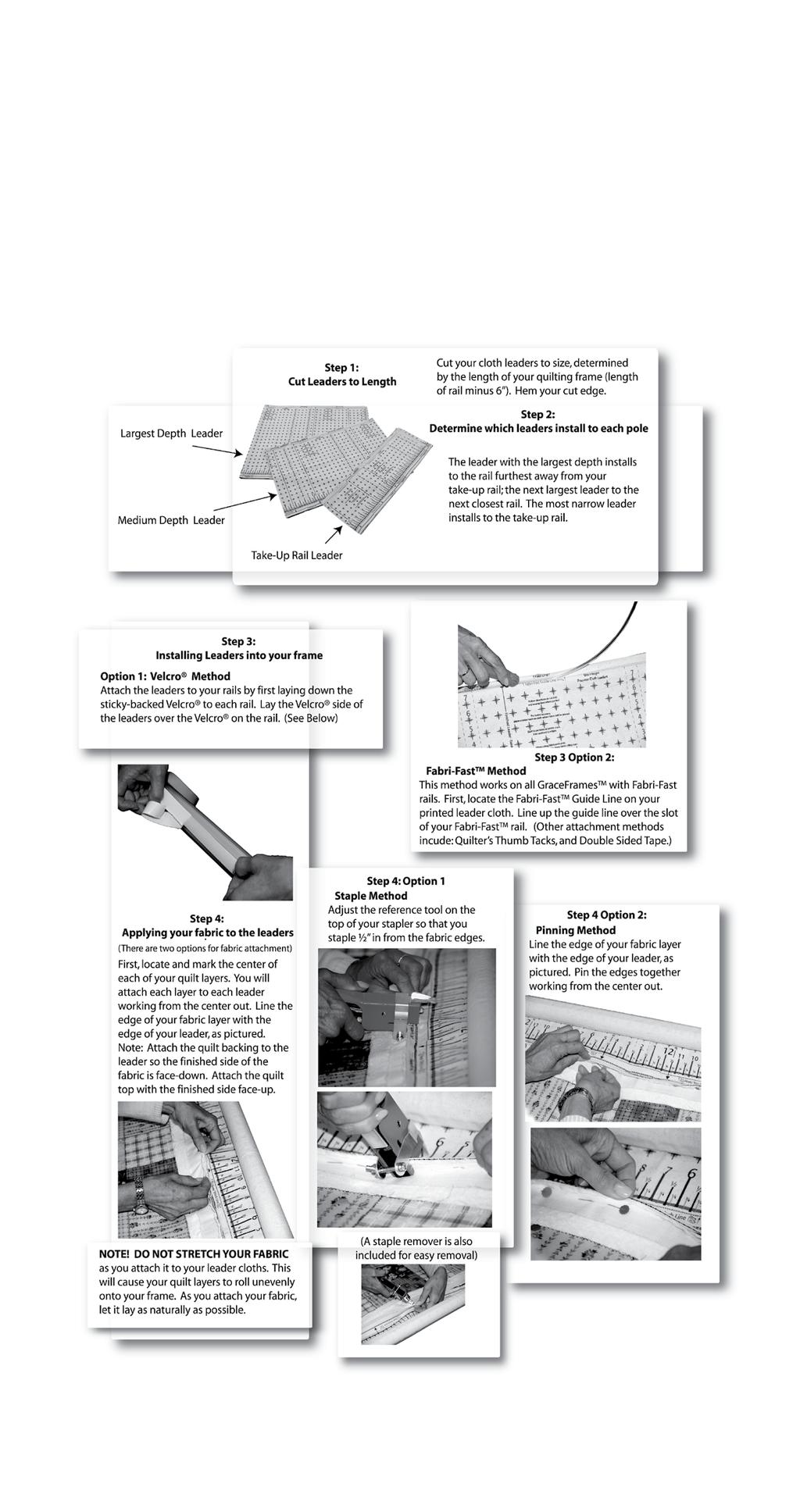
17 Fabric Installation: Using leader cloths enable you to finish your quilt completely, to the end, without having to take your quilt off the rails. Fabric installation overview Step 1: Install quilt top to 2nd rail and roll up. 2nd rail take up leader Step 2: Install quilt backing to the 3rd rail and roll up. Step 3: Install batting to the 4th rail and roll up. Step 4: Attach quilt backing to take up rail. Step 5: Attach batting to take up rail. Step 6: Attach quilt top to take up rail. 1st rail (take up rail) top fabric (Step 1) 2nd rail 3rd rail 3rd rail backing (Step 2) 1st rail batting (Step 3) 4th rail batting top fabric backing Fig. FI-1 4th rail Fig. FI-2 Leader Cloth installation instructions Preview. (for more details see instructions on page 20.) Top fabric leader Step L1: Draw a straight line all the way across each of your (conduit) fabric rails with a black magic marker. Backing leader 2nd 1st Take up leader Step L2: Mark the center of each cloth leader on both edges (Length-wise). Also place a mark at the center of each of the (conduit) fabric rails. Always measure to the center of the rails from the same end of the quilting frame. Draw the lines at the center of each rail so that they cross the lines previously drawn across the rails. Step L3: Now you need to attach your leaders to their respective rails. The fabric can easily be attached to the rails by applying a piece of adhesive backed hook Velcro along the lines that you have drawn down each fabric rail. 3rd 4th Fig. FI-4 Note: This illustration shows the cloth leaders installed on each rail prior to your quilt layers being installed. Pg.17
18 Installing fabric layers onto (conduit) rails STEP 1: Quilt top to 2nd rail Step 1-1: Determine which will be the front and back edges of your quilt. Step 1-2: Line up the center of your fabric layer with the center of the cloth leader on the 2nd Rail. Pin the back edge of your top to the leader cloth. This is to be done with the finished side of the fabric facing up. 3rd take up leader top fabric 1st 2nd backing batting Step 1-3: Do not stretch or pull the fabric during this process. Let it lay as naturally as possible. Step 1-4: Roll your leader and top onto the 2nd rail completely. Again, be sure the fabrics stay lined up. Smooth out any wrinkles as you roll by brushing the fabric from the center out, being very careful not to stretch or pull the fabric excessively. NOTE! It is important that you roll the rail the proper direction so the fabric rolls onto the 2nd rail the right way (when fabric rolls off the rail toward the take-up rail, it should roll under and off the rail. See Fig. FI-5). Fig. FI-5 2nd 3rd 4th top fabric 1st STEP 2: Quilt backing to 3rd rail Step 2-1: To begin, determine which will be the front and back edges of your quilt backing (make sure the backing is not wider than your quilting frame). Note: If your backing is made up of more than one piece of fabric, cut your selvedges off and flatten them out to allow the backing the proper give it needs. Step 2-2: Line up the center of your fabric layer with the center of the cloth leader on the 3rd rail. Pin the back edge of your backing to the leader cloth. This is to be done with the finished side of the fabric facing down. Note: Do not stretch or pull the fabric during this process, let it lay as naturally as possible. Step 2-3: Roll your leader and backing onto the 3rd rail completely. Watch to make sure the fabric stays lined up. Smooth out any wrinkles as you roll by brushing the fabric from the center out. However, be very careful not to stretch or pull the fabric excessively. Fig. FI-6 2nd 3rd Fig. FI-7 4th 1st batting 4th Note: It is important that you roll the rail the proper direction so the fabric rolls over and onto the 3rd rail (Fig. FI-5). Pg.18
19 STEP 3: Batting Step 3-1: A light, bonded batting is recommended. Step 3-2: Center the batting on the 4th rail. Roll the batting onto the 4th rail, being sure to roll the proper direction so that it, like the quilt top, comes off the rail from the bottom when unrolling. quilt top backing 3rd batting 2nd 1st STEP 4: Attaching your quilt layers to the take-up rail Step 4-1: Take the edge of the quilt backing and pin it along the straight line of the take up rail leader in a smooth manner, without stretching your fabric. Fig. FI-8 Step 4-2: Next, bring your batting up in between the 3rd rail and 2nd rail and drape over the backing. Lay it along the pin line of your backing on the take up rail cloth leader. Step 4-3: Finally, bring the quilt top up over the backing and batting and lay it over the batting along the pin line on the take up rail cloth leader. Pin your top and batting along the same line as your backing so that it is smooth. 4th Rolling your fabric When you have completed your work area and are ready to move to the next, simply release the ratchet stops on the 2nd and 3rd rails, allowing them to roll freely. Then, roll the 1st rail forward, rolling the completed work area onto that rail. TIP! As you roll forward, the quilt will accumulate on the 1st rail. Be sure to raise the take up rail brackets slightly as needed, so that the bottom of the rolled up fabric stays about 1/8 above the throat plate of your sewing machine base. Failing to do so will cause your carriage assembly to roll less smoothly. Pg.19
20 Pg.20
21 Available accessories Stylus Adaptor: The Stylus adaptor allows you to mount the Pattern Perfect bracket to your top plate. Gracie Laser: The laser may be attatched through any of the available holes. Mounting Holes M6 Square Nut Laser Bracket M6 x 40mm Connector Bolt Bolt the laser to the laser bracket using the provided M6 X 40mm hex bolt, and the 3 wing knob, Pg.21
22 Queen Quilter Frame Setup - Addendum Queen Quilter- Table Splice Attachment Parts Required: 1) S- Table Splice 2) M6 X 40mm SBHC Screw 2) M6 Square Nut 6) 1/4-20 X 30mm Connector Bolt 4) 1/4-20 Square Nut Table Splice You will need to use the table splice when setting up your Queen Quilter quilting frame at 98. Step 1-1: Attach the table splice to the table brace using the two (2) 40mm SBHC screws, and two (2) 6mm square nuts as shown. (Make sure that the pre-installed T -nuts face down when placing the table splice onto the frame.) Step 1-2: Attach the 10, as well as the 40 tables to the table splice using (2) 1/4-20 X 30mm Connector bolts. The bolt s that go through the table splice will not need a square nut because they will thread into pre-installed T -nuts. Step 1-3: Finalize the attachment of the tables by installing the missing 1/4-20 X 30mm bolts, and 1/4 square nuts. 1/4 square nuts 1/4 X 30mm Connector Bolt M6 X 40mm SBHC Screw M6 square nuts Table Splice Pg.22
The Phoenix. Professional Quilting Frame. Copyright January 1, 2016 Jim M. Bagley, GraceWood, Inc (Reproduction Prohibited) Version 2.
 Version 2.") The Phoenix Professional Quilting Frame Copyright January 1, 2016 Jim M. Bagley, GraceWood, Inc (Reproduction Prohibited) Version 2.1 1 The Phoenix Professional Quilting Frame Parts List Box 1...3 Box
The Phoenix Professional Quilting Frame Copyright January 1, 2016 Jim M. Bagley, GraceWood, Inc (Reproduction Prohibited) Version 2.1 1 The Phoenix Professional Quilting Frame Parts List Box 1...3 Box
Machine Quilting Frame assembly, and instruction manual
 Machine Quilting Frame assembly, and instruction manual Table of Contents Parts List................. Pg. 2 Step 1 - Legs............... Pg. 4 Step 2 - Lower Leg Brace....... Pg. 5 Step 3 - Frame Ends..........
Depending on the size you ordered you will have either 5 Foot sections which will build the 10 Foot frame or 6 Foot sections which will build the 12
 XL Quilting Frame 1 Depending on the size you ordered you will have either 5 Foot sections which will build the 10 Foot frame or 6 Foot sections which will build the 12 Foot frame Printed 2 June 2014 Updated
Assembly Instructions. Copyright May 01, 2013 Jim M. Bagley, GraceWood, Inc (Reproduction Prohibited)
") Assembly Instructions Copyright May 01, 2013 Jim M. Bagley, GraceWood, Inc (Reproduction Prohibited) Table of Contents Part List Part List... 3 Assembly Steps Step 1-Foot Assembly... 5 Step 2-Leg Assembly...
Assembly Instructions Copyright May 01, 2013 Jim M. Bagley, GraceWood, Inc (Reproduction Prohibited) Table of Contents Part List Part List... 3 Assembly Steps Step 1-Foot Assembly... 5 Step 2-Leg Assembly...
The Mini Pinni Quilting Frame
 The Mini Pinni Quilting Frame Copyright September 2007 Jim M. Bagley, GraceWood, Inc (Reproduction Prohibited) Print Date 10-16-07 1 The Mini Pinni Quilting Frame By The Grace Company Part List Parts List
Q-Zone Hoop-Frame. Assembly Instructions. Copyright July 11, 2018 Grace Company (Reproduction Prohibited) Version 1.8
 Version 1.8") Q-Zone Hoop-Frame Assembly Instructions Copyright July 11, 2018 Grace Company (Reproduction Prohibited) Version 1.8 Table of Contents Table of Contents... i Warranty... ii Parts List Box 1...iii Box 2...
Q-Zone Hoop-Frame Assembly Instructions Copyright July 11, 2018 Grace Company (Reproduction Prohibited) Version 1.8 Table of Contents Table of Contents... i Warranty... ii Parts List Box 1...iii Box 2...
Continuum Frame Assembly Instructions
 Continuum Frame Assembly Instructions Copyright January 1, 2017 Jim M. Bagley, GraceWood, Inc (Reproduction Prohibited) Version 2.2 Table of Contents Continuum Frame Table of Contents... i Warranty...ii
Juki Quilting Frame. Assembly and Use Instruction Manual. Max Overall Dimensions: Length Crib: King: Tall: Wide: 42
 Juki Quilting Frame Assembly and Use Instruction Manual Max Overall Dimensions: Length Crib: 63 1 4 King: 128 1 4 Tall: 45 3 4-51 3 4 Wide: 42 Copyright January, 2015 Version 9.6 (Page 1) Contents Parts
Dream Fabric Frame Assembly Instructions
 Dream Fabric Frame Assembly Instructions Copyright May 01, 2015 Jim M. Bagley, GraceWood, Inc (Reproduction Prohibited) Version 1 Table Of Contents Parts List 3 Step 1: Table Set Up 6 Step 2: Install the
HQ Pole Upgrade Kit for HQ Adjustable Table and HQ QuilTable Assembly Instructions 1
 HQ Pole Upgrade Kit for HQ Adjustable Table and HQ QuilTable Assembly Instructions QF09775 The pole upgrade kit can be used with or without the QF09700 HQ Precison-Glide track upgrade kit. What s Included
Dream Fabric Frame Assembly Instructions
 Dream Fabric Frame Assembly Instructions Copyright January 1, 2016 Jim M. Bagley, GraceWood, Inc (Reproduction Prohibited) Version 2.4 Table Of Contents Parts List 3 Step 1: Table Set Up 6 Step 2: Install
MACHINE QUILTING FRAME
 MACHINE QUILTING FRAME YOU WILL NEED TO PURCHASE: 5 pieces of 1-1/4 thin wall metal conduit (EMT) cut to your preferred length for the rollers. (Maximum 120 ) DETERMINING YOUR ROLLER LENGTH: Determine
The Sturdy-Lite. Copyright December 2005 Jim M. Bagley, GraceWood, Inc (Reproduction Prohibited)
") The Sturdy-Lite Parts List Wood Parts List... 2 Hardware Parts List... 3 Care of Your Frame... 4 Assembly Steps: Step 1: Table Brace Assembly... 6 Step 2: Frame End Assembly... 6 Step 3: Leg to Frame Assembly...
The Sturdy-Lite Parts List Wood Parts List... 2 Hardware Parts List... 3 Care of Your Frame... 4 Assembly Steps: Step 1: Table Brace Assembly... 6 Step 2: Frame End Assembly... 6 Step 3: Leg to Frame Assembly...
HQ Studio2 Frame. Assembly Instructions. Table of Contents. What s Included
 HQ Studio2 Frame Assembly Instructions UPDATED NOVEMBER 2017 Table of Contents Parts List... page 2 Hardware List.... page 3 HQ Studio Frame Box Contents...page 4 Step 1- Frame Side Assembly... page 5
HQ Studio2 Frame. Assembly Instructions. Table of Contents. What s Included
 HQ Studio2 Frame Assembly Instructions UPDATED June 2018 Table of Contents Parts List... page 2 Hardware List.... page 3 HQ Studio Frame Box Contents...page 4 Step 1: Frame Side Assembly... page 5 Step
Equipped with the Professional Series Rails Table of Contents. Care, Finishing and Storage Quilting Instructions and Tips... Trouble Shooting...
 Z44 Fabri-Fast Edition Hand Quilting Frame Equipped with the Professional Series Rails Table of Contents Care, Finishing and Storage............................................ 2 Warranty.........................................................
GMQ 16 Adapter Set Assembly Instructions Copyright November, 2003 GraceWood, Inc. Table of Contents
 GMQ 16 Adapter Set Assembly Instructions Copyright November, 2003 GraceWood, Inc. Table of Contents Parts List.................................................................. 1 Assembly Instructions.......................................................3
TABLE OF CONTENTS CARE, FINISHING AND STORAGE... WARRANTY... PARTS LIST... ASSEMBLY STEPS STEP 1: LAMPHOLDER TO POLE MOUNT END ASSEMBLY...
 TABLE OF CONTENTS CARE, FINISHING AND STORAGE................................................ WARRANTY................................................................. PARTS LIST.................................................................
for HQ 18 Avanté HQ Studio Frame
 HQ Studio Frame for HQ 18 Avanté Assembly Instructions Table of Contents Parts List page 2 Hardware List page 3 HQ Studio Frame Box Contents page 4 Step 1- Frame Side Assembly page 5 Step 2- Table Assembly
Assembly Instructions. Table of Contents
 HQ Little Foot Assembly Instructions Back of Handi Quilter, Inc. 501 North 400 West North Salt Lake, UT 84054 1-877-697-8458 Front of 2015 Handi Quilter, Inc. www.handiquilter.com Printed in the United
THE GRACE EZ3 FABRI-FAST QUILTING FRAME
 THE GRACE EZ3 FABRI-FAST QUILTING FRAME TABLE OF CONTENTS CARE, FINISHING AND STORAGE..................................................... 2 WARRANTY..........................................................................
Quilting with The GraceHoop 2 TM
 Quilting with The GraceHoop 2 TM T h e G r a c e H o o p Squared Table of Contents Customer Service Information............................. 2 Care, Finishing and Storage...............................
This guide contains everything you need to set up and operate all three. Inspira Imperial Quilting Frame Assembly...2
 Congratulations on the purchase of your Husqvarna Viking Mega Quilter 18x8, Inspira Imperial Quilting Frame, and QBOT by Inspira! This guide contains everything you need to set up and operate all three.
Hardware and Components:
 Hardware and Components: (A) 5/16 x 2 Hex Bolt (B) 5/16 x 2-1/4 Hex Bolt (C) 5/16 x 2-1/2 Hex Bolt (D) 4X 5/16 x 3/4 Hex Bolt (E) 4X 5/16 x 1-1/4 Hex Bolt (F) 11X 5/16 Flat Washer (G) 12X 5/16 Nylock Nut
TABLE OF CONTENTS COPYRIGHT MAY 2003 REPRODUCTION PROHIBITED JIM M. BAGLEY GRACEWOOD, INC. PATENT PENDING
 TABLE OF CONTENTS CARE, FINISHING AND STORAGE................................................ 2 WARRANTY.................................................................. 2 PARTS LIST.................................................................
Hardware and Components:
 Hardware and Components: (A) 4X 5/16 x 1 Carriage Bolt (B) 2X 5/16 x 2-1/4 Carriage Bolt (C) 2X 5/16 x 3-1/4 Hex Bolt (D) 2X 5/16 x 3/4 Hex Bolt (E) 2X 5/16 x 1-1/4 Hex Bolt (F) 5/16 x 2-1/4 Hex Bolt (G)
HQ Studio Frame Two-Foot Section Assembly Instructions From Twelve-Foot to Ten-Foot
 HQ Studio Frame Two-Foot Section Assembly Instructions From Twelve-Foot to Ten-Foot HQ Studio Frame Two-Foot Includes: Includes one (1) two-foot table frame with plastic top, two (2) two-foot track supports,
WOLF LOOM DOUBLE BACK BEAM
 WOLF LOOM DOUBLE BACK BEAM Assembly Instructions Find out more at schachtspindle.com Schacht Spindle Company 6101 Ben Place Boulder, CO 80301 p. 303.442.3212 f. 303.447.9273 2017 Schacht Spindle Company,
HQ Precision-Glide Track Upgrade 2 Extension Kit for HQ Studio Frame Part# QF09750
 HQ Precision-Glide Track Upgrade 2 Extension Kit for HQ Studio Frame Part# QF09750 Important Note: Upgrading the track system on the HQ Studio Frame requires the use of this 2 Extension Kit (Part #QF09750),
MobileTrak5 Installation Instructions
 MobileTrak5 Installation Instructions PLEASE OPEN ALL BOXES & CHECK TO MAKE SURE YOU HAVE ALL PIECES REQUIRED READ ALL INSTRUCTIONS BEFORE STARTING Tools Required for Assembly 7/16, 1/2 Wrench Phillips
HQ Gallery Frame. Assembly Instructions QM HQ Gallery Frame Box Contents
 HQ Gallery Frame Assembly Instructions QM31301 HQ Gallery Frame Box Contents Box # Parts (See pages 2 and 3 for descriptions and quantities) 1 Table sections, items listed in What s Included below 2 End
CV1B Sliding Table Installation and Setup Guide
 CV1B Sliding Table Installation and Setup Guide Tech Mark, Inc 7901 Industry Drive North Little Rock, AR 72117 tel (501) 945-9393 fax (501) 945-0312 www.tech-mark.com email: info@tech-mark.com The CV1B
BABY WOLF LOOM. Assembly Instructions for Knocked-Down Looms
 BABY WOLF LOOM Assembly Instructions for Knocked-Down Looms BEFORE YOU BEGIN Please read through the directions before beginning to assemble your loom. Unpack the loom parts carefully. Do not throw away
WOLF PUP LOOM TM & WOLF PUP LT LOOM TM
 WOLF PUP LOOM TM & WOLF PUP LT LOOM TM Assembly Instructions FL3000 FL3006 FL3009 WOLF PUP WOLF PUP LT Find out more at schachtspindle.com Schacht Spindle Company 6101 Ben Place Boulder, CO 80301 p. 303.442.3212
User Instructions Multiline Otter Scoreboard Caddy Assembly
 List of parts: User Instructions Multiline Otter Scoreboard Caddy Assembly Single Caddy Double Caddy 1 1 Base assembly with attached wheels 2 4 1 1 2 4 4 8 10 20 12 Uprights (60 or 74 aluminum extrusion)
ClearSpan Twist-of-the-Wrist Assembly Instructions
 ClearSpan Twist-of-the-Wrist Assembly Instructions Curved-Wall for Roll-Up Side Flat-Wall for Curtain Application 2008 ClearSpan All Rights Reserved. Reproduction is prohibited without permission. Revision
HQ Gallery Frame. Assembly Instructions QM HQ Gallery Frame Box Contents
 HQ Gallery Frame Assembly Instructions QM31301 HQ Gallery Frame Box Contents Box # Parts (See pages 2 and 3 for descriptions and quantities) 1 Table sections, items listed in What s Included below 2 End
400A 40113V, 401A 40120V, & 401AL 40120VL ALUMINUM VERTICAL 4000 LB LIFT INCLUDES SCREW LEG ASSEMBLY INSTRUCTIONS
 12/11/07 PAGE 1 OF 12 400A 40113V, 401A 40120V, & 401AL 40120VL ALUMINUM VERTICAL 4000 LB LIFT INCLUDES SCREW LEG ASSEMBLY INSTRUCTIONS Thank you for purchasing our product! *Please read these instructions
INSTALLATION LS MODEL
 INSTALLATION LS MODEL Page 2 TABLE OF CONTENTS Section 1: Included parts... pg 4 Section 2: Installing the Shirley Stitcher II on Quilt Frame.. pg 5 Section 3: Connecting Shirley Stitcher II to Tin Lizzie
HQ 24 Fusion Frame Assembly 1
 HQ 24 Fusion Frame Assembly Instructions HQ 24 Fusion Frame Box Contents Box # Parts (See pages 2 & 3 for descriptions and quantities) 1 Table sections, items listed in What s Included below 2 End leg
The Bowflex Revolution XP Home Gym Assembly Instructions. P/N: Rev ( /0 )
") P/N: 001-7057 Rev ( /0 ) The Bowflex Revolution XP Home Gym Assembly Instructions 2 Table of Contents Before You Start... 2 Tools You Will Need / Hardware Contents... 3 Box Contents... 6 Assembling Your
P/N: 001-7057 Rev ( /0 ) The Bowflex Revolution XP Home Gym Assembly Instructions 2 Table of Contents Before You Start... 2 Tools You Will Need / Hardware Contents... 3 Box Contents... 6 Assembling Your
Thank you for purchasing out product! *Please read these instructions and follow them step by step. *
 Page 1 of 7 AD17 AA DS 4 X 16 T12 Thank you for purchasing out product! *Please read these instructions and follow them step by step. * STEP 1. Slide two support posts (REF. # 24) into the two outside
earl Pearl Frame Instruction Addendum How to Load Fabric to Frame Model BLQF Model BLQF
 earl Pearl Frame Instruction Addendum How to Load Fabric to Frame Model BLQF Model BLQF www.babylock.com Step 1 Anatomy of the Frame Note: A little preparation the first time you use your quilting frame
WILDING WALLBEDS INSTALLATION INSTRUCTION Side Mount
 WILDING WALLBEDS INSTALLATION INSTRUCTION Side Mount For Wallbed models: Do-It-Yourself Insturction booklet C92 WARNING! ALL MURPHY/WALLBED SYSTEMS CONTAIN STORED ENERGY. FAILURE TO USE AND FOLLOW THESE
HQ Electromagnetic Channel Locks
 HQ Electromagnetic Channel Locks Table of Contents Overview... 2 Kit Contents... 2 Tools Required... 5 Installation... 5 Using the HQ Electromagnetic Channel Locks... 10 Troubleshooting... 11 Overview
SCHACHT STANDARD FLOOR LOOMTM
 SCHACHT STANDARD FLOOR LOOMTM FL3109 FL3111 FL3113 FL3115 FL3121 FL3123 FL3125 FL3127 FL3310 FL3312 FL3314 FL3316 FL3322 FL3324 FL3326 FL3328 Assembly instructions LOW CASTLE LOOM IN MAPLE Find out more
S48-L12-SC AND G48-L12-GC STEEL PORTA-DOCK S82 SC 6 X 12 PLATFORM AND G82 GC 6 X 12 PLATFORM
 PAGE 1 OF 6 PORTA-DOCK, INC. S48-L12-SC AND G48-L12-GC STEEL PORTA-DOCK S82 SC 6 X 12 PLATFORM AND G82 GC 6 X 12 PLATFORM Thank you for purchasing our product! *Please read these instructions and follow
OPERATIONS MANUAL. Port-O-Slitter
 Tapco Products Company The World Leader in Specialty Tools for the Professional Port-O-Slitter OPERATIONS MANUAL General instructions, set up, accessories and guide to using your portable precision slitting,
Fortress Fe Posts must always be secured to the deck framing. Fortress Fe Posts should never be attached to only the deck boards.
 Installation Instructions for Fortress Horizontal Cable Panel System with UB-05 Brackets and Fe Posts It is the responsibility of the installer to meet all code and safety requirements, and to obtain all
Replacing the Reciprocator on the SWF Compact Series Machine (601C and 1201C)
") Follow the instructions below to replace the reciprocator in the SWF Compact series machines. The tools required can be found in the tool kit that came with the machine. Preparation 1. First, place the
Follow the instructions below to replace the reciprocator in the SWF Compact series machines. The tools required can be found in the tool kit that came with the machine. Preparation 1. First, place the
INSTALLATION INSTRUCTIONS
 INSTALLATION INSTRUCTIONS For Wallbed models: Do-It-Yourself BOOKLET #C90 WARNING! ALL MURPY/WALLBED SYSTEMS CONTAIN STORED ENERGY. FAILURE TO USE AND FOLLOW THESE INSTRUCTIONS DURING THE INSTALLATION
Installation and Assembly - Universal Articulating Swivel Double-Arm for 42" - 60" Plasma Screens
 Installation and Assembly - Universal Articulating Swivel Double-Arm for 42" - 60" Plasma Screens Models: PLAV 70-UNL, PLAV 70-UNL-S PLAV 70-UNLP, PLAV 70-UNLP-S R This product is UL Listed. It must be
Side Mount INSTRUCTION BOOKLET #C122 BED STYLE: PARK CITY
 Side Mount BED STYLE: PARK CITY INSTRUCTION BOOKLET #C1 WARNING! ALL MURPHY/WALLBED SYSTEMS CONTAIN STORED ENERGY. FAILURE TO USE AND FOLLOW THESE INSTRUCTIONS DURING THE INSTALLATION PROCESS COULD RESULT
The Grace Z44 TM New Millennium Quilting System
 The Grace Z44 TM New Millennium Quilting System Table of Contents Care, Finishing and Storage......................................x Warranty....................................................x Parts
INSTRUCTION BOOKLET #C20
 INSTRUCTION BOOKLET #C0 WARNING! ALL MURPHY/WALLBED SYSTEMS CONTAIN STORED ENERGY. FAILURE TO USE AND FOLLOW THESE INSTRUCTIONS DURING THE INSTALLATION PROCESS COULD RESULT IN SEVERE PERSONAL INJURY TO
ABM International, Inc. Navigator Assembly Manual
 ABM International, Inc. 1 1.0: Parts List Tablet (Qty. 1) Tablet mount (Qty. 1) NOTE: Mount may appear and operate different then image below Control Box (Qty. 1) Motor Power Supply (Qty. 1) 2 X-axis motor
INSTRUCTION BOOKLET #34. For Wallbed models: KING SIZE SIERRA WITH STORAGE HEADBOARD
 For Wallbed models: KING SIZE SIERRA WITH STORAGE HEADBOARD INSTRUCTION BOOKLET #34 WARNING! ALL MURPHY/WALLBED SYSTEMS CONTAIN STORED ENERGY. FAILURE TO USE AND FOLLOW THESE INSTRUCTIONS DURING THE INSTALLATION
END FRAMES. End frames built using pressure treated 2x4 (1 1/2" x 3 1/2") 36" 34" 7/16" pilot hole. 5 1/2" x 1/2" lag bolt 8" wheel 23"
 36 34 7/16 pilot hole. 5 1/2 x 1/2 lag bolt 8 wheel 23") END FRAMES End frames built using pressure treated 2x4 (1 1/2" x 3 1/2") 23" 17 1/2" (B) (B) Measure from the bottom of your stone to 1" below the lip to get your measurement. 17 1/2"(B) 36" 34" 1/2" flat
END FRAMES End frames built using pressure treated 2x4 (1 1/2" x 3 1/2") 23" 17 1/2" (B) (B) Measure from the bottom of your stone to 1" below the lip to get your measurement. 17 1/2"(B) 36" 34" 1/2" flat
PORTA-DOCK, INC. AP17 APD DS 4 X 16 T12 AW17 CPD DS 4 X 16 T12
 Page 1 of 7 PORTA-DOCK, INC. AP17 APD DS 4 X 16 T12 AW17 CPD DS 4 X 16 T12 *For Beige Decking Add the Letter B to Model* Thank you for purchasing out product! *Please read these instructions and follow
May 14, Installation Manual
 May 14, 2012 Installation Manual Contents MAG TRACKER Components...1 Mount Installation...7 Module Installation & Grounding...11 Maintenance...14 Warranty......14 Contact Information......14 May 14, 2012
ELEVEN COLLABORATIVE. CONFERENCE TOPS Assembly Instructions
 ELEVEN COLLABORATIVE Table of Contents SUPPORT BRACE ASSEMBLY.... 3 TABLE BASE FRAME ASSEMBLY.... 4 LEG ATTACHMENT.... 5 TOP JOINING PLATE ASSEMBLY... 6 TOP CLAMP/TOP SPACER INSTALLATION.... 7 TOP PLACEMENT
N. 15th Street, Middlesboro, KY FLIP TARP DUMP BODY INSTALLATION INSTRUCTIONS
 1-800-248-7717 1002 N. 15th Street, Middlesboro, KY 40965 FLIP TARP DUMP BODY INSTALLATION INSTRUCTIONS Congratulations on your purchase of a Mountain Flip Tarp Dump Body tarping system. With tarping systems
Assembly Instructions
 18' W x 10' H or 12' H Peak Style Frame Assembly Assembly Instructions Before you start: 2+ individuals recommended for assembly, approximate time 3 hours. Recommended tools: Power Drill, Safety Glasses,
Insolroll Clutch Operated Shades Installation Instructions Installation Instructions
 All clutch operated shades are shipped fully assembled and ready for installation. Mounting screws are not provided. Screws for chain guide installation to meet the child safety standards are provided.
General Guidelines:
 ASSEMBLY INSTRUCTIONS Congratulations on your new Patriot Dock purchase. This manual contains instructions to assemble basic dock configurations for use at typical residential shoreline application. Please
Flat Panel Stand FPZ-655. for 32" to 55" Flat Panel Screens FEATURES. Reinforced universal adapter plate for a strong hold
 FPZ-655 Flat Panel Stand for 32" to 55" Flat Panel Screens For a viewing experience that really stands out, Peerless FPZ-655 Universal Flat Panel Stand for 32" 55" flat panel TVs provides a brilliant combination
200A FLB VERTICAL 22113V LIFT W/CHAIN DRIVE WINCH
 PG. 1 OF 11 PORTA-DOCK, INC. 200A FLB VERTICAL 22113V LIFT W/CHAIN DRIVE WINCH STEP 1. Separate and group like parts and fasteners together. Locate the winch side member with the longer upright tube and
MyStudio VS53 Versa Sweep Setup Instructions
 MyStudio VS53 Versa Sweep Setup Instructions MISSION STATEMENT Pro Cyc, Inc. is the world leader in design and sales of modular infinity backgrounds. Our studio systems are recommended by every major company
BMW R1100/R1150GS Instructions for Mounting Medium or Large Pack Rack and Micatech Top Case with Mount Kit
 BMW R1100/R1150GS Instructions for Mounting Medium or Large Pack Rack and Micatech Top Case with Mount Kit Thank you for purchasing the Micatech Pack Rack and Top Case, with R1100/1150GS mount kit. Please
Heavy Duty Ceiling Tilt Mount Installation Manual
 HD-CTM-5580 Heavy Duty Ceiling Tilt Mount Installation Manual *This Installation requires a minimum of two people. For your safety: Read the complete instruction manual before starting an installation
MODEL T28173/T28174 ROLLER TABLES INSTRUCTIONS
 MODEL T28173/T28174 ROLLER TABLES INSTRUCTIONS FOR MODELS MFD. SINCE 10/17 For questions or help with this product contact Tech Support at (570) 546-9663 or techsupport@grizzly.com Rails Rollers Reversible
INSTRUCTION BOOKLET #C21. For Wallbed models: KING SIZE
 For Wallbed models: KING SIZE INSTRUCTION BOOKLET #C1 WARNING! ALL MURPHY/WALLBED SYSTEMS CONTAIN STORED ENERGY. FAILURE TO USE AND FOLLOW THESE INSTRUCTIONS DURING THE INSTALLATION PROCESS COULD RESULT
Fortress Fe Posts must always be secured to the deck framing. Fortress Fe Posts should never be attached to only the deck boards.
 Installation Instructions for FortressCable H-Series Cable Panel System With UB-05 Brackets and Fe Posts It is the responsibility of the installer to meet all code and safety requirements, and to obtain
CONTENTS TOOL LIST U P S I D E I N N O V A T I O N S, L L C RAMP AND STEP SYSTEM ASSEMBLY INSTRUCTIONS. Revised: June 2013
 U P S I D E I N N O V A T I O N S, L L C RAMP AND STEP SYSTEM ASSEMBLY INSTRUCTIONS TOOL LIST Required Tools: - Reciprocating Saw with Metal Cutting Blade - Drill - 7/16 Drill Bit for Metal Drilling -
For additional assistance call
 The following pages will help guide you through the process of assembling your new 48 custom prize wheel. Choose an assembly area with plenty of room to lay your pieces on the floor and also a bench or
MPA-9000 Universal Ceiling Projector Mount Kit
 I N S T R U C T I O N M A N U A L Universal Ceiling Projector Mount Kit The Universal Ceiling Projector Mount provides a unique, simplified method of ceiling mounting your inverted projector. This low
Trak-Slider Instructions
 Trak-Slider Instructions 1/4-20 x 3/4" Hex Head Bolt 1/4-20 Flanged Hex Nut Gusset 1/4-20 x 1/2" Allen Cap Screw 1/4-20 Nylock Nut Rivet 1/4-20 x 3/8" Pan Head Phillips Machine Screw 1/4 USS Flat Washer
INSTALLATION INSTRUCTIONS
 INSTALLATION INSTRUCTIONS Furniture Solutions: 68 Shipstation with Storage Shelf Model Numbers: PB001 (D9001, D9010N, D9021, D9030, D9032/D9033, D9098, RC4054) Introduction This document provides the Pitney
Roll In W/L Dock PAGE 1
 Roll In W/L Dock PAGE 1 1 2 3/8 X 1 CARRIAGE BOLT SS 3/8 FLANGE NUT BRASS 3 4 1/2-13 X 1.25 SQ BOLT SS 1/2 SQ NUT BRASS 5 3/8-16 X 2.5" BOLT SS PAGE 2 6 7 BRACE BRKT SINGLE AXLE TUBE 8 9 3" AXLE WASHER
RAMPAGE P R O D U C T S. INSTALLATION INSTRUCTIONS BRONCO ZIPPER FASTRACK TOP PART #984xx BRONCO TOOLS REQUIRED
 RAMPAGE P R O D U C T S 84 (+/- 1/4 ) INSTALLATION INSTRUCTIONS BRONCO ZIPPER FASTRACK TOP PART #984xx BRONCO 1966-1977 TOOLS REQUIRED 3/8 WRENCH 7/16 WRENCH ½ WRENCH #2 PHILLIPS SCREWDRIVER 1/8 DRILL
ABM International, Inc.
 ABM International, Inc. Lightning Stitch required 1 1.0: Parts List head and motor assembly (Qty. 1) Reel stand (Qty. 1) Needle bar frame clamp (Qty. 1) Motor drive (Qty. 1) 2 Cable harness with bracket
ClearSpan End Frame Kit 30' Wide x 11' High
 ClearSpan End Frame Kit 30' Wide x 11' High Diagram shows the end frame kit for an end wall without a door. (Door and end panel are purchased separately.) Rafter and mounting feet shown in the above diagram
Strata. urniture. Adriana Instructions. Parts in the Arm Box: Parts in the Body Box: Watch our assembly videos at
 1A Watch our assembly videos at www.strataf.com/videos Parts in the Arm Box: Arm - Outside View Arm - Inside View 1B Parts in the Body Box: Back Deck x 1 Seat Deck x 1 with the Feet attached Back Panel
ASSEMBLY GUIDE. Mia Narrow Bookcase
 ASSEMBLY GUIDE Mia Narrow Bookcase Components: Upon unpacking your bookcase from it s delivery box, you should have the pieces shown. Follow the steps on the next pages to assemble your new bookcase. Step
ASSEMBLY AND ADJUSTMENT
 EPPA MONITOR ARM EPPA Rev A 10/17 Model EPPA-XXX ASSEMBLY AND ADJUSTMENT EPPA MONITOR ARM PARTS AND TOOLS PLEASE REVIEW these instructions before beginning the assembly and adjustment procedures. Check
1503 Follow Spot Yoke, Source Four LED
 1503 Follow Spot Yoke, Source Four LED Rev 1.0 2016 City Theatrical, Inc. Getting Started with the City Theatrical Follow Spot Yoke for source four LED Congratulations on the purchase of your City Theatrical
MITCHELL WREATH RINGS NO-HAMMER ASSEMBLY INSTRUCTIONS
 MITCHELL WREATH RINGS NO-HAMMER ASSEMBLY INSTRUCTIONS METAL STAND WITH WOOD STAND WITH PAGE 2 OF 10 MASTER PARTS LIST HEAD ASSEMBLY LINKAGE ASSEMBLY HOOK LEVER ASSEMBLY FOOT PEDAL ASSEMBLY ALL FASTENERS
Installation and Assembly - Universal Articulating Swivel Double-Arm for 42" - 60" Plasma Screens
 Installation and Assembly - Universal Articulating Swivel Double-Arm for 42" - 60" Plasma Screens Models: PLAV 70-UNL, PLAV 70-UNL-S PLAV 70-UNLP, PLAV 70-UNLP-S R This product is UL Listed. It must be
Drake Off Road Hood Hold Downs Installation Guide
 Installation Time: 30 Minutes Tools Required: Drake Off Road Hood Hold Downs Installation Guide 3/8 drive ratchet 13mm socket 10mm socket (deep-well socket helpful) 13mm wrench (2x) 4mm allen wrench 5mm
 INSTRUCTION BOOKLET #C0 Watch step by step installation instructions at: https://www.wallbedsbywilding.com/wallbed-installation-studio-series/ WARNING! ALL MURPHY/WALLBED SYSTEMS CONTAIN STORED ENERGY.
Assembly Instructions
 InTandem Table System November 20 InTandem Table System - Worksurface #4 x/" 4 wood screw power beam Tools Provided T-0 Extended Torx Driver T-25 Torx Driver Additional Tools Required Soft protective
OPERATIONS MANUAL. Port-O-Slitter
 OPERATIONS MANUAL Port-O-Slitter General instructions, set up, accessories and guide to using your portable precision slitting, rib forming and perforating system Saves hours on large siding jobs! Featuring:
 INSTRUCTION BOOKLET #C10 Watch step by step installation instructions at: https://www.wallbedsbywilding.com/wallbed-installation-studio-series/ WARNING! ALL MURPHY/WALLBED SYSTEMS CONTAIN STORED ENERGY.
8.5 Ton Assembly Instructions
 8.5 Ton Assembly Instructions Parts list for assembly. 6- Legs 2 1/2 Angle X 92 Long 6- Cone Supports 2 Angle X 60 Long 6-1 1/4 Angle X 27 1/4 Long. 12-1 1/4 Angles X 42 Long 6-1 Flat Straps 23 3/4 Long
PO BOX 130 CLEAR LAKE, MN
 WWW.WALKSONWATER.COM PO BOX 130 CLEAR LAKE, MN 55319 320-743-3333 PARTS LIST FOR 30115# VERTICAL BOAT LIFT 2-Back Leg Uprights 1 right, 1 left (BL) 1-Front Leg Upright (FL) 1-Winch Leg Upright (WU) 2-Bottom
ASSEMBLY INSTRUCTIONS MANUAL
 PAGE 1 OF 9 RECOMMENDED TOOLS FOR ASSEMBLY: ALLEN WRENCH (INCLUDED) BOX WRENCH (INCLUDED) PHILLIPS SCREW DRIVER (NOT INCLUDED) PARTS IN CARTON: ALLEN WRENCH SCREWS (20 EACH) ROUND HEAD SCREWS (8 EACH)
Tradewinds Amplify Display System Instructions
 Table of Contents Packing & Unpacking... Standard Kits... Component Identification... Primary Components Vertical Pole Top... Vertical Pole Bottom... Horizontal... Cross/Hanging Bar... Amplify Shelf Package
Basic steps to time the Gammill quilting machine s rotary sewing hook
 Basic steps to time the Gammill quilting machine s rotary sewing hook 1.) Turn the machine off and unplug it. 2.) With the needle bar in the raised position, remove the bobbin and bobbin case. 3.) Remove
Medium Pro Table Top Stand
 Medium Pro Table Top Stand Build Manual Thank you for purchasing a Foam-Flite model airplane stand. Your Foam-Flite stand was designed by modelers just like you looking for an economical and versatile
EPPA2-KIT DUAL MONITOR ARM CONVERSION
 EPPA2-KIT DUAL MONITOR ARM CONVERSION EPPA2-KIT Rev A 10/17 Model EPPA2-KIT-XXX ASSEMBLY AND ADJUSTMENT EPPA2-KIT PARTS AND TOOLS PLEASE REVIEW these instructions before beginning the assembly and adjustment