V4 Premium Kit. Prusa i3 Build Guide
|
|
|
- Baldwin Sparks
- 5 years ago
- Views:
Transcription


1 V4 Premium Kit Prusa i3 Build Guide
2 Hi! Congratulations on your purchase of the DIYElectronics.co.za Prusa I3 kit, the best South African 3D Printer Kit! Hopefully this should serve as complete guide to get your printer setup and printing! This guide will start with a step by step mechanical assembly, followed by electronic wiring and calibration. Please take note, before continuing with this this guide! Due to the nature of Rapid Prototype 3D printed parts, cleaning-up, drilling, filing, cutting of the plastic parts may be necessary. This is important. If you want your build to go smoothly you MUST read all the *Notes and *Tips along the way. Following this guide will save you time and hassle. Contents [1] Y-Axis... 3 [1.1] Y Carriage Sub-assembly:... 5 [1.2] Y-Bed Undercarriage Sub-assembly... 6 [1.3] Y-Axis assembly... 7 [1.4] Y-Belt Idler pulley Sub-assembly... 9 [1.5] Y-motor mount Sub-assembly [1.6] Y Motor Sub-assembly [1.7] Y-Axis timing belt
3 [1.8] Outer end plates [2] X-Axis [2.1] X-Axis Tensioner Sub-assembly [3] Z Axis [4] XZ-axis Mate [5] YZ axis Mate [6] Electronics and Extruder Assembly [7] Endstops
4 [1] Y-Axis 3


5 Front gasket 1 y-bed carriage 1 624f flanged bearing 2 Rear gasket M10x480 threaded rod 1 y-axis motor mount 2 Bearing holder 1 LM8UU linear bearing 8 Nema 17 stepper motor 4 1 M8x475 smooth linear rod front outer plate Front inner plate Back inner plate Back outer plate 2 y-belt tensioner 1 y-belt holder 1 IEC mains and switch 1 USB extender 1 GT2 20tooth pulley 1 M10 Nut 12 1 M10 Washer 1 M3 machine screws, washers, nuts 1 M4 machine screws, washers, nuts 1 8 4
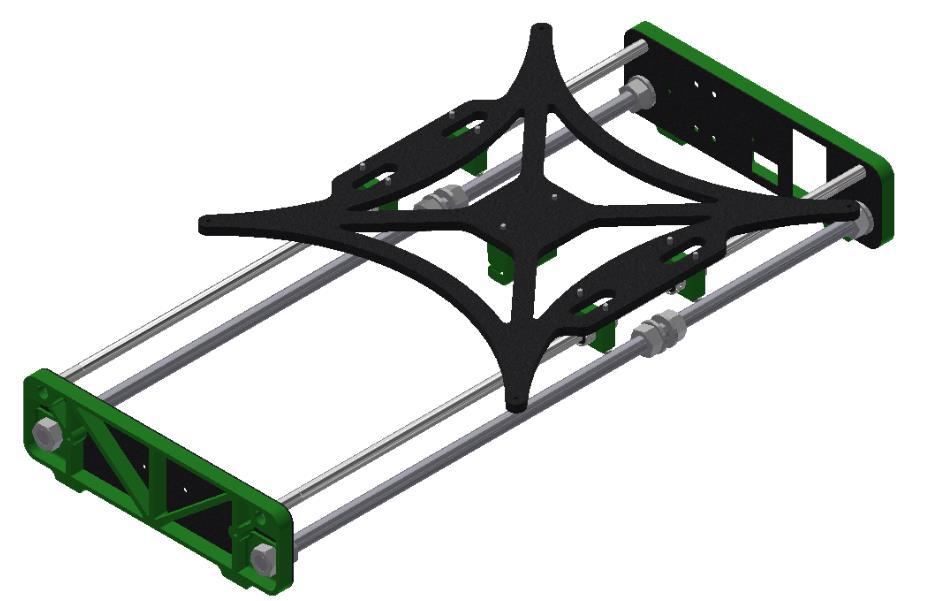
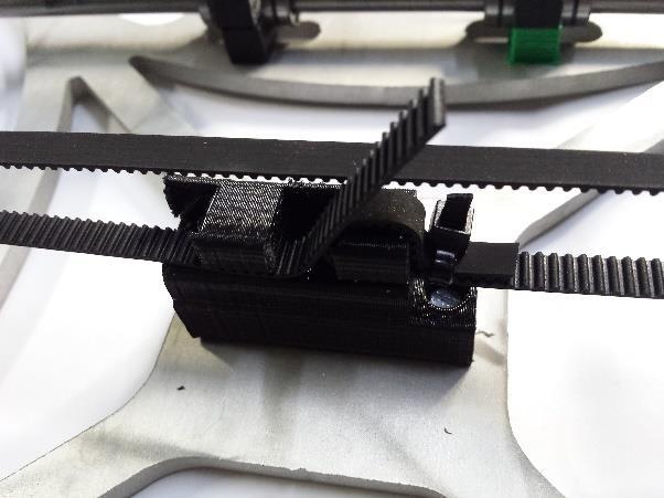
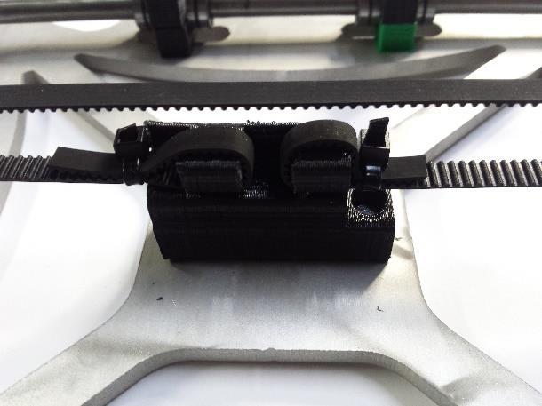
![[1.1] Y Carriage Sub-assembly: Parts needed: 1x aluminum carriage 2x M8x 475mm smooth stainless steel rod 4x LM8UU linear bearings 8x printed bearing holders 1x printed y-belt holder 2x M3x 10mm](/docs-images/82/86051690/images/6-2.jpg "ch screws 8x M3x 25mm ch screws 10x M3 washers Slide two LM8UU linear bearings onto each smooth 475 mm rod. Fix the printed Y-belt to the carriage with the use of two M3x 10 machine screws.")

6 [1.1] Y Carriage Sub-assembly: Parts needed: 1x aluminum carriage 2x M8x 475mm smooth stainless steel rod 4x LM8UU linear bearings 8x printed bearing holders 1x printed y-belt holder 2x M3x 10mm ch screws 8x M3x 25mm ch screws 10x M3 washers Slide two LM8UU linear bearings onto each smooth 475 mm rod. Fix the printed Y-belt to the carriage with the use of two M3x 10 machine screws. Do not worry about the orientation of the Y- belt, it does not make a difference. Line the bearings, rods, and printed bearing holders with the holes in the Y-carriage as shown in the top diagram. Fasten it all down with eight M3x25 screws (don t forget the washers) TIP* Make sure the linear rods slide smoothly within the bearings. Overtightening the bearing holders will restrict movement. 5
![[1.2] Y-Bed Undercarriage Sub-assembly Parts needed: 2x M10x480 threaded rod 8x M10 nuts 8x M10 washers Thread M10 nuts and washers onto the two M10 threaded](/docs-images/82/86051690/images/7-2.jpg "rods as seen in the image above. Make sure that the distance between the outer washer on one side and the nearest inner washer is 155 mm. This is important.")
7 [1.2] Y-Bed Undercarriage Sub-assembly Parts needed: 2x M10x480 threaded rod 8x M10 nuts 8x M10 washers Thread M10 nuts and washers onto the two M10 threaded rods as seen in the image above. Make sure that the distance between the outer washer on one side and the nearest inner washer is 155 mm. This is important. 6
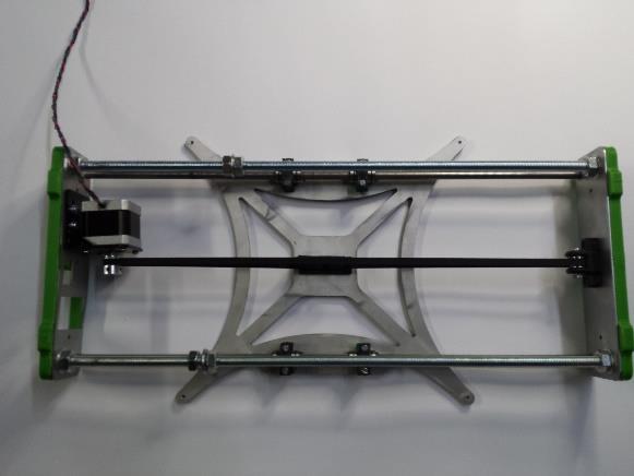
![[1.3] Y-Axis assembly Parts needed: Y Carriage Sub-assembly Y Bed Undercarriage Sub-assembly Inner front plate Inner back plate Front printed gasket](/docs-images/82/86051690/images/8-2.jpg "Back printed gasket 4x M10 nuts Assemble the Y-Axis by sliding the plates and gaskets onto the ends of the smooth and threaded rods.")

8 [1.3] Y-Axis assembly Parts needed: Y Carriage Sub-assembly Y Bed Undercarriage Sub-assembly Inner front plate Inner back plate Front printed gasket Back printed gasket 4x M10 nuts Assemble the Y-Axis by sliding the plates and gaskets onto the ends of the smooth and threaded rods. The M8 smooth rods should fit snugly into the printed gasket holes. There should be exactly enough threaded rod protruding from the printed gaskets to fit M10 nuts onto. Tighten these four M10 nuts with a size 17 spanner. NOTE: Make sure that you tighten the 4 M10 nuts on a flat surface to ensure a flat Y-Axis assembly. 7
9 8
![[1.4] Y-Belt Idler pulley Sub-assembly Parts needed: 1x printed Y-belt idler (Bearing holder) 2x 624 flanged bearings 1x M4x 25 machine screw 2x M4 washers 1x](/docs-images/82/86051690/images/10-2.jpg "M4 nyloc nut 2x M3x 20 machine screws 2x M3 washers 2x M3 nuts First fasten the printed Y-Belt idler bracket to the front inner end plate.")

10 [1.4] Y-Belt Idler pulley Sub-assembly Parts needed: 1x printed Y-belt idler (Bearing holder) 2x 624 flanged bearings 1x M4x 25 machine screw 2x M4 washers 1x M4 nyloc nut 2x M3x 20 machine screws 2x M3 washers 2x M3 nuts First fasten the printed Y-Belt idler bracket to the front inner end plate. Use M3x20 machine screws and fasten into M3 nuts which are to be held captive in the printed bracket. Feed an M4x25 screw though the bracket and TWO 624 flanged bearings butted up against each other. Don t forget about the washers on either side. Tighten with an M4 nyloc nut. Do not overtighten to allow your bearing to rotate smoothly. 9
![[1.5] Y-motor mount Sub-assembly Parts needed: 1x motor mount 4x M4x10 machine screws 8x M4 washers 4x](/docs-images/82/86051690/images/11-2.jpg "M4 nuts Fix the Y-motor mount to the rear inner end plate using 4x M4x10 screws, washers, and nuts as")

11 [1.5] Y-motor mount Sub-assembly Parts needed: 1x motor mount 4x M4x10 machine screws 8x M4 washers 4x M4 nuts Fix the Y-motor mount to the rear inner end plate using 4x M4x10 screws, washers, and nuts as shown in the image. Make sure that the mount is straight and parallel to the top of the end plate. NOTE* The distance from the edge of the motor mount to the edge of the end plate needs to be about 40 mm 10
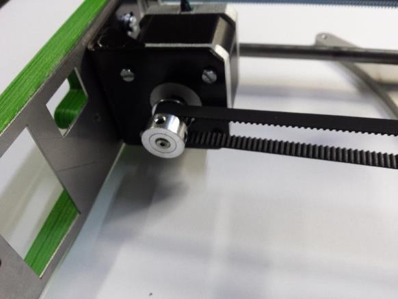
![[1.6] Y Motor Sub-assembly Parts needed: 1x Nema 17 stepper motor 1x GT2 20t pulley (with 2 M3 grub screws) 4x M3x8 machine screws 4x M3 washers 1x Allen key Fix the Y axis Nema](/docs-images/82/86051690/images/12-2.jpg "17 stepper motor to the motor mount using four M3x10 machine screws with washers as seen in the picture above.")

12 [1.6] Y Motor Sub-assembly Parts needed: 1x Nema 17 stepper motor 1x GT2 20t pulley (with 2 M3 grub screws) 4x M3x8 machine screws 4x M3 washers 1x Allen key Fix the Y axis Nema 17 stepper motor to the motor mount using four M3x10 machine screws with washers as seen in the picture above. Tighten well, but not enough to strip the thread of the stepper motor. TIP* Try to orientate your cables so that they come out the bottom of the motor, this will help you in the long run with uniformity of your printer. Then slide the GT 2 pulley onto the stepper motor shaft. Position the pulley so that the center of the teeth line up with the center of the idler bearing on the other side of the axis (see the next section) 11
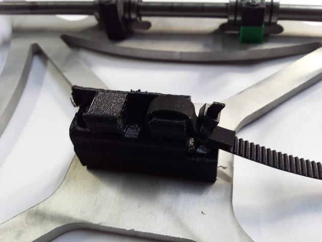
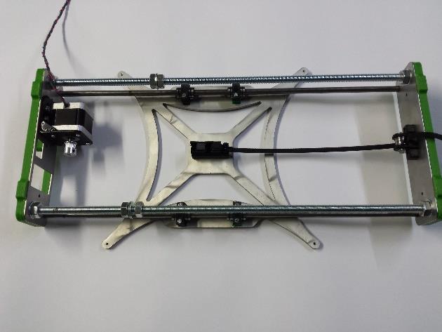
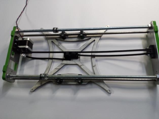
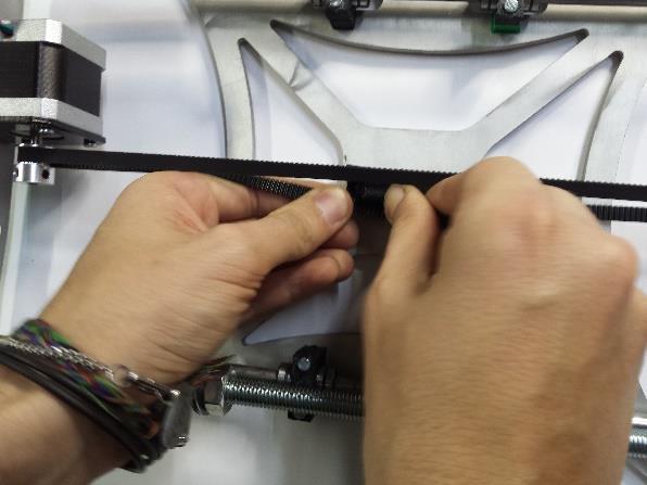
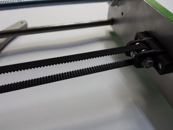
![[1.7] Y-Axis timing belt Parts needed: 1x Timing belt 4x Cable ties Make sure that the centre of the GT2 pulley, centre of the Y-Belt holder, and the centre of the Y-belt idler bearing are all in](/docs-images/82/86051690/images/13-2.jpg "line with each other. If they are not, you will need to loosen the pulley grub screws and position the pulley (possibly flip it around).")
13 [1.7] Y-Axis timing belt Parts needed: 1x Timing belt 4x Cable ties Make sure that the centre of the GT2 pulley, centre of the Y-Belt holder, and the centre of the Y-belt idler bearing are all in line with each other. If they are not, you will need to loosen the pulley grub screws and position the pulley (possibly flip it around). If this still doesn t work you will need to loosen the Y-motor mount M4 screws and reposition the mount. Following this, flip the entire Y-axis around and attach the timing belt. 12
14 13
![[1.8] Outer end plates **NOTE** The cutout for the IEC connecter is no longer present on the rear](/docs-images/82/86051690/images/15-2.jpg "outer plate.")

15 [1.8] Outer end plates **NOTE** The cutout for the IEC connecter is no longer present on the rear outer plate. The IEC connecter now is included in the PSU kit Parts needed: 1x rear outer end plate 1x USB male to USB female adapter 2x M3x10 machine screws 2x M3 washers 5x M3x20 machine screws 10x M3 washers 5x M3 nuts Fix the female end of the USB adapter to the rear outer end plate as seen in the images. 14


16 Next up is fixing the outer end plates to the front and rear gaskets. Do this by inserting three M3x20 screws with washers through the read outer end plate through the gasket and rear inner end plate. Place washers on the protruding ends of the screws and tighten with M3 nuts. 15
17 16
18 Well done! Your printer s Y-Axis assembly is now complete! 17
19 [2] X-Axis 18
 2x LM8UU linear bearings 7x")


20 Parts needed: 420mm smooth linear rods (x-axis) 2x LM8UU linear bearings 7x 320mm smooth linear rods (z-axis) 2x Nema 17 stepper motor 1x Printed x-end 1x GT2 pulley (with grub screws) 1x Printed x-end motor 1x M3x10mm machine screw 3x Printed x-axis carriage 1x M4x25 machine screw 1x Y-axis tensioner 1x M4x20 machine screw 2x F624 idler bearing 2x M4 washer 3x M4 Nyloc nut 1x M4 nut 2x 19


21 STEP 1 Insert two M8x420 linear rods into the printed x-end motor bracket STEP 2 Slide two LM8UU linear bearings onto the bottom rod and one on the top Snap the printed x-axis carriage onto the bearings. Make sure that the bearings line up perfectly with their mounting cavities! STEP 3 Press fit the other printed x-end part onto the two linear rods. The distance between the two inner faces of the x-end parts (or the length of exposed linear rod) needs to be 347 mm. 20
22 STEP 4 Slide two LM8UU linear bearings onto each M8x320mm z-axis linear rods Press fit the bearings (with rods inserted) into their cavity slots. It is VERY important that the bearings seat perfectly into their slots. Check that the x-axis runs smoothly up and down the bearings. If there is excess friction this would indicate improper seating or alignment of the bearings. NOTE: At this point you need to drill out the 10mm and 3mm holes in each x-end. This is to make your life easier later. 21


23 STEP 5 Slide the 20tooth GT2 pulley onto the shaft of the Nema 17. Tighten the two grubscrews with a suitable Allen key thereby fixing the pulley to the motor shaft. TIP* Try to orientate your cables so that they come out the bottom of the motor, this will help you in the long run with uniformity of your printer. STEP 6 Fix the Nema 17 stepper motor to the printed x-end bracket using three M3x10 machine screws. Make sure that the center of the pulley s teeth are aligned with the centre of the slot of the printed x-end 22
![[2.1] X-Axis Tensioner Sub-assembly STEP 7 Should be M4 nyloc nut Fix the two 624f bearings to the](/docs-images/82/86051690/images/24-1.jpg "printed x- axis tensioner with an M4x25 machine screw, two M4 washers, and an M4 nyloc nut.")

24 [2.1] X-Axis Tensioner Sub-assembly STEP 7 Should be M4 nyloc nut Fix the two 624f bearings to the printed x- axis tensioner with an M4x25 machine screw, two M4 washers, and an M4 nyloc nut. STEP 8 Slide an M4 nut into the rear captive slot. Screw an M4x20 machine screw into the nut. NOTE: Do not overtighten the screw which houses the two bearings. The bearings should be able to rotate freely on the screw s axis 23


25 STEP 9 Slide the x-axis tensioner Sub-assembly though the printed right side x-end. NOTE** This can sometimes be a tight fit. You don t want to break the x-end so sanding or filing of the sides of the tensioner may be required. STEP 10 Once the tensioner is in, insert an M4x20 machine screw with washer and nut through the tensioner s slot (indicated by the red arrow). This screw acts as a backstop which the M4 screw in the rear of the tensioner sits against. TIP: Make sure to leave the rear tensioning screw as unscrewed as possible (The image shows the screw fully screwed in and tensioned). You only want to tension it once you have installed the timing belt. 24
![[3] Z Axis Parts needed: Aluminium 6mm frame 1x](/docs-images/82/86051690/images/26-2.jpg "Nema 17 stepper motor with leadscrew Printed")

26 [3] Z Axis Parts needed: Aluminium 6mm frame 1x Nema 17 stepper motor with leadscrew Printed z-axis bottom left corner Printed z-axis bottom right corner M3x10 machine screw 2x 1x 1x 12x M3 washer 6x 25


27 STEP 1 Fix the printed z-axis bottom left and right corners to the laser cut aluminium frame. Using 6 M3x10 machine screws. NOTE: You need to make sure that the machine screws are screwed tight, but do not over tighten and strip the thread of the frame. STEP 2 Fix the Nema 17 stepper motors to the z-axis motor mount corners with M3x10 machine screws and washers. Root the cables through the holes in the frame at the bottom. **NOTE** Remove the two brass leadscrew nuts and keep them aside for the next section. 26
![[4] XZ-axis Mate 1x Z-axis Sub-assembly 1x X-axis](/docs-images/82/86051690/images/28-2.jpg "Sub-assembly Printed z-axis top left corner Printed")

28 [4] XZ-axis Mate 1x Z-axis Sub-assembly 1x X-axis Sub-assembly Printed z-axis top left corner Printed z-axis top right corner Leadscrew nut M3x10 machine screw M3x20 machine screw M3 nut 1x 1x 2x 4x 4x 4x 27


29 STEP 1 Slide the x-axis Sub-assembly down over the z-axis lead screws. You need to make sure that the distance between the x-axis ends are perfect!! The z-axis 320mm linear rods need to be press fitted into the bottom z- axis corner mount holes (red arrow). You might need to use a mallet to lightly tap them into place. STEP 2 Press fit the left top z corner on top of the left 320mm linear rod. Fix the left side corner to the aluminium frame with two M3x10 machine screws. 28
30 STEP 3 Press fit the top right z corner to the right 320mm linear rod. Use a mallet to tap the x-end (indicated by red arrows) until the top right z-axis corner line up with the aluminium frame holes. STEP 4 Once you are satisfied that everything lines up and that the linear rods and leadscrews are ALL parallel with NO bowing Use two M3x10 machine screws to fix the top right side z- corner to the frame. NOTE: The entire x-axis needs to be able to traverse up and down the z-axis linear rods smoothly without any interference. 29


31 STEP 5 Thread the two leadscrew nuts onto the leadscrews until the flanged section of the nut seats flush up against the top of the x-ends. STEP 6 Make sure that the threaded brass nut holes line up with the x-end holes and use four M3x20 machine screws. You should be able to manually rotate the leadscrews with your hands and traverse the x-axis up and down without too much brass nut friction. If the leadscrews and nuts stick at any point along the z-axis then there is an alignment issue!!! 30
![[5] YZ axis Mate ZX axis](/docs-images/82/86051690/images/32-3.jpg "Sub-assembly 1x Y axis")

 Bed springs 4x M3x25")
32 [5] YZ axis Mate ZX axis Sub-assembly 1x Y axis Sub-assembly 1x Assembled Kit 1x Kapton heater pad and thermistor 1x (Attached to above Aluminium Bed) Bed springs 4x M3x25 countersunk machine screws 4x 31


33 STEP 1 Slot the Y-axis assembly down into the slots of the aluminium frame. Keep in mind the 155mm clearance distance mentioned in the first section. STEP 2 Tighten the M10 nuts with a size 17 spanner. Make sure that the feet of the aluminium frame and the printed gaskets are level! *TIP Working on a flat surface will help. STEP 3 Install the timing belt similarly to how it was done on the Y-axis. See example picture on the right. Secure ends by x-carriage with cable ties. *Note You may need to break away the supports on the x-carriage to insert the belt if there is any 32


34 STEP 5 Using four M3x25 countersunk screws, fix the print bed to the y-carriage. Make sure that there are springs wedged between the bed and the carriage. Ensure that the heater pad wires under the aluminium bed face the back of the printer. 33
![[6] Electronics and](/docs-images/82/86051690/images/35-3.jpg "Extruder Assembly Arduino")


35 [6] Electronics and Extruder Assembly Arduino Mega 1x Ramps 1.4 1x 12V power supply kit 1x Printed standoff M4x10 machine screw M3x20 4x 2x 4x Auto Bed Levelling Kit Extruder and hotend Sub-assembly 34

.")
36 STEP 1 You will receive both your Arduino Mega and Ramps 1.4 control board assembled and mated together. Evenly apply force to the edges of both boards to pry the two apart. Fix the Arduino mega to the frame using four M3x20 machine screws and standoffs between the frame and the bottom of the Arduino. Once it is secure, press the Ramps 1.4 shield back into place (try not bend any pins and make sure that all the pins are inserted fully). STEP 2 Secure the 12V power supply to the frame using two M4x10 machine screws. The Power supply comes with a protective cover attached. This cover also houses the IEC power socket and fused on/off switch! 35


37 STEP 3 - *REFER TO CHARLSTRUDER INSTRUCTIONS ON HOW TO ASSEMBLE THE EXTRUDER* STEP 4 Mounting Extruder and Auto Bed Level Probe Mount Fix the completed extruder and Auto Bed Levelling Probe mount to the x-axis carriage using two M3x35 machine screws, M3 washers, and M3 nuts. Tip: You might need to remove the hotend from the clamp temporarily if it is in the way and you can t get your screwdriver on either side of the hotend fins. Your printer should look like this. Nearly there!! 36
![[7] Endstops X Parts needed: Y Printed X-Endstop holder 1x Printed X-Endstop holder](/docs-images/82/86051690/images/38-1.jpg "End switch 1x 2x You will not need this Z-Endstop due to your inductive probe STEP")


38 [7] Endstops X Parts needed: Y Printed X-Endstop holder 1x Printed X-Endstop holder End switch 1x 2x You will not need this Z-Endstop due to your inductive probe STEP 1 Z Time to attach your two end stops, one for each axis as seen in the image. First thing you need to do is insert the end switches into the printed parts. These press fit into place and have wires pre-soldered on. Make sure that you feed the connector and wire through the back of the holder before you press them down into place. 37


39 STEP 2 Snap the x-axis end switch holder onto the two M8 smooth rods. STEP 3 Snap the y-axis end switch assembly to the M10 threaded rod. The top hook keeps the mount vertical. 38


40 STEP 4 Now it s time to position the two end switch assemblies. The point of this is to ensure the tip of the nozzle homes to the front left corner of the bed. First up is the x-axis. Position the X end-switch assembly so that the tip of the nozzle lines up with the left edge of the print bed when the switch makes contact with the x-carriage. Next is the y-axis. The Y end switch assembly needs to be positioned so that the tip of the print nozzle lines up with the front edge of the print bed. The switch actuates up against the edge of the plastic bearing holder. 39
Part 7 Assembling the X axis
 Part 7 Assembling the X axis 1 2 The X axis is a key part of the printer, it carries the extruder on a carriage that moves the extruder laterally in the X axis. The x axis itself is moved vertically on
Kossel Rev B Build Guide V1.0
 Kossel Rev B Build Guide V1.0 1 Table of Contents: Step 1: BASE ASSEMBLY Gathering parts: Building the Corners and Base: Step 2: UPPER ASSEMBLY Building Upper: Step 3: VERTICAL RAIL INSTALLATION Building
Assembly Instructions Beta Prusa Standard & Deluxe
 Assembly Instructions Beta Prusa Standard & Deluxe 3D Printer Version 2.6 Date Page 1 / 67 General data about the assembly instructions for an incomplete machine according to appendix VI of the EG machinery
Assembly Instructions. Beta Prusa DualX 3D Printer
 Assembly Instructions Beta Prusa DualX 3D Printer Version 2.6 Date Page 1 / 72 General data about the assembly instructions for an incomplete machine according to appendix VI of the EG machinery directive
The Portable Open Source 3D Printer
 http://web.archive.org/web/201502142011/http://www.tantillus.org/build_3.html Page 1 of 12 captures 12 Oct 12 - Feb 15 The Portable Open Source 3D Printer Home Start Case X/Y Axis Extruder Z Axis Electronics
Assembly Instructions Beta Prusa Standard & Deluxe
 13/11/12 Assembly Instructions Beta Prusa Standard & Deluxe 3D Printer Version 1.0 Date 13/11/12 Page 1 / 66 General data about the assembly instructions for an incomplete machine according to appendix
M2 Assembly. M2 Sub-Assemblies mm Belt Sub-Assembly mm Belt Sub-Assembly Spider Sub-Assembly... 4
 M2 Assembly Table of Contents M2 Sub-Assemblies... 3 630mm Belt Sub-Assembly... 3 702mm Belt Sub-Assembly... 3 Spider Sub-Assembly... 4 Idler Bolt Sub-Assembly... 8 Y Motor Sub-Assembly... 9 X Motor Sub-Assembly...
4. Z-axis assembly. 4. Z-axis assembly. Written By: Josef Prusa manual.prusa3d.com Page 1 of 18
 4. Z-axis assembly Written By: Josef Prusa 2017 manual.prusa3d.com Page 1 of 18 Step 1 Get the necessary tools 13/17mm spanners 3.6mm flathead screwdriver Needle-nose pliers 2.5 and 1.5mm Allen key Step
3. X-axis assembly. 3. X-axis assembly. Written By: Jakub Dolezal manual.prusa3d.com/ Page 1 of 13
 3. X-axis assembly Written By: Jakub Dolezal 2018 manual.prusa3d.com/ Page 1 of 13 Step 1 Tools necessary for this chapter Needle-nose pliers for zip tie trimming. 2.5mm Allen key for M3 screws 2mm Allen
AM8 Printer A metal frame for your Anet A8 By Pheneeny v1.0 April 20, 2017
 AM8 Printer A metal frame for your Anet A8 By Pheneeny v1.0 April 20, 2017 Please read this entire document before printing parts or building this frame Disclaimer: This guide is for informational purposes
Delta Rostock mini G2& G2s Building instruction
 Delta Rostock mini G2& G2s Building instruction Safety Instructions ShenZhen GETECH CO.,LTD Building the printer will require a certain amount of physical dexterity, common sense and a thorough understanding
5. Extruder Assembly
 5. Extruder Assembly Guide for the assembly of the Extruder. Written By: Josef Prusa 2017 manual.prusa3d.com Page 1 of 22 Step 1 Get the necessary tools 2.5 and 1.5 mm Allen key Needle-nose pliers Step
Assembly Instructions
 Assembly Instructions Note: Prior to assembly, be sure to remove all printing pads from the printed parts and also be sure to sort through and organize all of your hardware before assembly this will help
Code Product Qty 1 Top Vertex 3 2 Hot End Housing 1 3 Bottom Vertex 3 4 Print Platform Lock 3 5 End Stop Holder 3 6 Filament Feeder Motor Bracket 1 7
 List of Parts Code Product Qty 1 680mm Extrusion 3 2 Power Supply 1 3 240mm Extrusion 9 4 42mm Nema 17 Stepper Motor 3 5 Slider-Hotend Connecting Rod 6 6 48mm Nema 17 Stepper Motor 1 7 Linear Rail with
Printrbot Simple (Model 1403) Rev F Printrboard
 Rev F Printrboard") Printrbot Simple (Model 1403) Rev F Printrboard Printrbot Simple is currently shipping with the Rev F Printrboard. Check which rev Printrboard your Simple kit includes and use the corresponding instructions.
Printrbot Simple (Model 1403) Rev F Printrboard Printrbot Simple is currently shipping with the Rev F Printrboard. Check which rev Printrboard your Simple kit includes and use the corresponding instructions.
Assembly Guide for Printrbot - Simple Maker s Edition 1405
 Assembly Guide for Printrbot - Simple Maker s Edition 1405 Last update: March 2016 Please Note: be careful on the steps that are underlined 1 Contents Tools Needed:... 3 First step: Check components and
Assemble Instruction of Geeetech Acrylic. Prusa I3 Pro C
 Assemble Instruction of Geeetech Acrylic Prusa I3 Pro C Version 04-11-2016 Safety Instructions Building the printer will require a certain amount of physical dexterity, common sense and a thorough understanding
Assemble Instruction of Geeetech Acrylic Prusa I3. Pro & pro B
 Assemble Instruction of Geeetech Acrylic Prusa I3 Pro & pro B Version 04-11-2016 Safety Instructions Shenzhen GETECH CO.,LTD Building the printer will require a certain amount of physical dexterity, common
Assembly Instructions
 Assembly Instructions Note: Prior to assembly, be sure to remove all printing pads from the printed parts and also be sure to sort through and organize all of your hardware before assembly this will help
Assemble Instruction of Geeetech Acrylic Prusa I3. pro C
 Assemble Instruction of Geeetech Acrylic Prusa I3 pro C Safety Instructions Shenzhen GETECH CO.,LTD Building the printer will require a certain amount of physical dexterity, common sense and a thorough
Document version: 1.1. Beagle Build manual
 Document version: 1.1 Beagle Build manual TABLE OF CONTENTS Table of contents...2 About the Beagle...3 Change history...4 Safety warnings...4 Required tools...5 1. Bars & Printed parts examination...6
Step 1 Assemble Base Frame Parts: 2040 Aluminium profile 250mm 1pcs Base Plate 1pcs M4-8mm screw 3pcs M4 T-Nut 3pcs
 Step 1 Assemble Base Frame 2040 Aluminium profile 250mm 1pcs Base Plate 1pcs M4-8mm screw 3pcs M4 T-Nut 3pcs Put the aluminium profile on the base plate, secure them with 3pcs M4-10mm screws & T-Nut Step
ABM International, Inc. Navigator Assembly Manual
 ABM International, Inc. 1 1.0: Parts List Tablet (Qty. 1) Tablet mount (Qty. 1) NOTE: Mount may appear and operate different then image below Control Box (Qty. 1) Motor Power Supply (Qty. 1) 2 X-axis motor
LYMANBOT 3D PRINTER V3 Construction Manual
 LYMANBOT 3D PRINTER V3 Construction Manual Page 1 Read this whole Manual before starting to construct this Printer. User excepts all liability for the use of this Manual and the construction of this Printer.
Step 1 Assemble Base Frame
 Step 1 Assemble Base Frame Parts: 2040 Aluminium profile 250mm 1pcs Base Plate 1pcs M4-8mm screw 3pcs M4 T-Nut 3pcs Put the aluminium profile on the base plate, secure them with 3pcs M4-10mm screws & T-Nut
Titan Aero Assembly. Titan Aero Assembly. Learn to assemble your Titan Aero. Written By: Gabe S e3d-online.dozuki.
 Titan Aero Assembly Learn to assemble your Titan Aero Written By: Gabe S. 2018 e3d-online.dozuki.com/ Page 1 of 26 INTRODUCTION The Titan Aero is a very similar build to a Titan and a V6 put together (which
0. Disassembly. Disassembly of the MK2 printer and upgrading to the MK2S using the upgrade kit. Written By: Jakub Dolezal
 0. Disassembly Disassembly of the MK2 printer and upgrading to the MK2S using the upgrade kit. Written By: Jakub Dolezal 2018 manual.prusa3d.com/ Page 1 of 12 Step 1 Preparing the printer Ensure the printer
(Assembling Guide supplied by imakr ) with the support of MyMiniFactory.com
 with the support of MyMiniFactory.com") (Assembling Guide supplied by imakr ) with the support of MyMiniFactory.com Summary Congratulations on beginning on your journey into 3D printing with the STARTT 3D printer. In this guide, you will have
(Assembling Guide supplied by imakr ) with the support of MyMiniFactory.com Summary Congratulations on beginning on your journey into 3D printing with the STARTT 3D printer. In this guide, you will have
Inspiration taken from Reprap Mendel Sketchup Model by Capo: om/3dwarehous e/details? mid=86dc5e3cc ad914839c51e370
 Goal: Provide a visual guide of the steps needed to construct a Prusa Mendel Printer. The instructions contained within are copied verbatim from the reprap.org wiki: http://reprap.org/wiki/prusa as of
IMPORTANT SAFETY INSTRUCTIONS
 ASSEMBLY MANUAL IMPORTANT SAFETY INSTRUCTIONS! WARNING SHARP EDGES Use caution during assembly and operation of the 3D printer to ensure no sharp edges will cut you. Inspect the printer for any damage
re3d Assembling Gigabot: "Flatpack"
 re3d Assembling Gigabot: "Flatpack" Your Gigabot was assembled, calibrated, tested, and taken apart for shipping purposes. All you need to do is reassemble it, and you're ready to go! Written By: Chris
Geeetech Delta Rostock mini G2 pro / G2s pro Building Instruction
 Geeetech Delta Rostock mini G2 pro / G2s pro Building Instruction (Document version: 04-11, 2016) CONTENT Safety Instructions... 1 Preparation... 2 1 Base Assembly... 3 1.1 Motor holder assembly... 3 1.2
HQ Precision-Glide Track Upgrade 2 Extension Kit for HQ Studio Frame Part# QF09750
 HQ Precision-Glide Track Upgrade 2 Extension Kit for HQ Studio Frame Part# QF09750 Important Note: Upgrading the track system on the HQ Studio Frame requires the use of this 2 Extension Kit (Part #QF09750),
BIGBOT ASSEMBLY INSTRUCTIONS. 1/18/2017 V0.5
 BIGBOT ASSEMBLY INSTRUCTIONS www.bigbot-3d.com 1/18/2017 V0.5 FOREWORD: PLEASE TAKE CARE WHEN HANDLING THE GANTRY. THE ASSEMBLY SHOULD BE HANDLED ONLY BY THE ALUMINUM FRAME, AND AVOID TOUCHING OR LIFTING
Heacent 3D printer assembly manual. Prusa i3
 Heacent 3D printer assembly manual Prusa i3 Y-axis assembly 1. Y axis motor section: Find the belowing parts bag, Y-axis motor Assembled parts are separated as shown below, note that the motor between
Elimination of Elevator Bounce
 For the Agilent Archon Autosampler Rework Instructions CAUTION This kit is intended for use by Agilent Service personnel only. Elevator Removal 1 Open top cover. 2 Open front lower door. 3 Remove vial
EPPA2-KIT DUAL MONITOR ARM CONVERSION
 EPPA2-KIT DUAL MONITOR ARM CONVERSION EPPA2-KIT Rev A 10/17 Model EPPA2-KIT-XXX ASSEMBLY AND ADJUSTMENT EPPA2-KIT PARTS AND TOOLS PLEASE REVIEW these instructions before beginning the assembly and adjustment
Ford Pick Up Rear leaf Spring Kit Installation Instructions
 1948-1956 Ford Pick Up Rear leaf Spring Kit Installation Instructions 1-800-984-6259 www.totalcostinvolved.com Parts 48 inch leaf (2) springs (4) U-bolts 3/8-24 x l 1/4bolts (16) & nuts (2) 1/2-20 x 4
001-Component-build. Build the following Contraptor components before assembly:
 001-Component-build Build the following Contraptor components before assembly: http://www.contraptor.org/make-linear-rail-v2#assembly http://www.contraptor.org/make-linear-bearings-v2#assembly http://www.contraptor.org/make-sliding-elements#assembly
OX CNC. Mechanical Assembly Instructions. S.A. Brown & Maker Store
 OX CNC Mechanical Assembly Instructions S.A. Brown & Maker Store v1.2 07 2017 Contents About The Maker Store Ox CNC Kit... 2 Unpack and Check All Components... 2 Tools Required... 2 Pre-Assembly Notes...
Ender-3 3D Printer. Instructions for assembly
 Ender-3 3D Printer Instructions for assembly This guide is for the Ender-3 3D printer. Select the correct input voltage to match your local mains (220V or 110V). Because of software/hardware upgrades and
Welcome! Table of Contents
 Welcome! The folks at Random Idea Generator Shop would like to thank you for purchasing our 3D printer kit. We are dedicated to providing an easy to build kit with customizable options to meet your requirements.
3D PRINTER. Pack 11. Anything you can imagine, you can make! 3D technology is now available for you at home! BUILD YOUR OWN
 BUILD YOUR OWN Pack 11 Anything you can imagine, you can make! 3D PRINTER Compatible with Windows 7 & 8 Mac OS X 3D technology is now available for you at home! BUILD YOUR OWN 3D PRINTER CONTENTS PACK
INVENT3D Printer Kit Disassembly Instructions
 INVENT3D Printer Kit Disassembly Instructions Version 6 AST2 10/26/16 1 I. General Disassembly Instructions Use the case layer drawings to ensure that components are stored in the appropriate location
Shenzhen GETECH CO.,LTD GEEETECH. Building Instructions of Geeetech Prusa I3 X
 Building Instructions of Geeetech Prusa I3 X CONTENT CONTENT... 2 Safety Instructions...3 Preparation...4 Unfold the box and check the package list... 5 1. Assemble the threaded rods of Y axis... 6 2.
Aluminum frame packing list of Smart Laser CO2
 Aluminum frame packing list of Smart Laser CO2 1 805mm V-slot 20mm*40mm 1 2 780mm V-slot 20mm*40mm 2 3 860mm Aluminum frame 20mm*40mm 3 4 177mm Aluminum frame 20mm*40mm 1 5 85mm Aluminum frame 20mm*40mm
AndyMark DART 12.
 AndyMark DART 12 Part Number Description QTY These Parts Are Pre-Assembled by AndyMark am-0031 Bearing, 3/16"ID (R3) 1 am-0209 Bearing, 3/8"ID 1614ZZ 2 am-1028 Screw, #10-32x3/8 Pan Head Philips 8 am-1121
TRAILMATE METEOR ASSEMBLY MANUAL
 TRAILMATE METEOR ASSEMBLY MANUAL The Trailmate Meteor recumbent has been designed for easy assembly. This means more time to enjoy the smooth ride with single speed, 3 speed coaster brake and 21 speed
WorkBee CNC. Mechanical Assembly Instructions - Screw Driven
 WorkBee CNC Mechanical Assembly Instructions - Screw Driven Table of Contents 1.0 Getting Started 2 1.1 About The Kit 3 1.2 Check Product Contents 3 1.3 Tools Required 3 1.4 Notes on Assembly 3 2.0 Assembly
Spiderbeam Balun Construction Guide
 BALUN CONSTRUCTION GUIDE Ver. 1.0 1 The components of the Balun Kit are in a plastic bag. Most of the components are inside the plastic case of the balun. The aluminum U-profile and the RG-142 Teflon Coax
ABM International, Inc.
 ABM International, Inc. Lightning Stitch required 1 1.0: Parts List head and motor assembly (Qty. 1) Reel stand (Qty. 1) Needle bar frame clamp (Qty. 1) Motor drive (Qty. 1) 2 Cable harness with bracket
Geeetech Acrylic I3 Pro C 3D Printer
 Geeetech Acrylic I3 Pro C 3D Printer Copyright Declaration The copyright of this manual belongs to the Shenzhen GETECH CO., LTD. (hereinafter referred to as the "Geeetech"), and all rights reserved. No
TL4100 Top 5 Build Tips
 TL4100 Top 5 Build Tips 1: Top Plate When assembling the top plate, align the top of the top plate brackets with the top of the rods. This can be done by placing a hard flat object (such as a ruler) on
Shapeoko XXL Assembly Guide
 Shapeoko XXL Assembly Guide 04/27/2016 XXL Packing LIst Item Qty Description Y-Carriage (left) 1 Y-Carriage (right) 1 X/Z Assembly 1 40 Rail 3 1 rail has mounting holes for controller Wasteboard Half 2
Installing the Partridge RA Extension on Losmandy G11
 Installing the Partridge RA Extension on Losmandy G11 Michael Herman July 20, 2015 Tools: 3/16 inch hex key (allen wrench) [If desired for DEC indicator ring friction improvement: flat screwdriver, and
Open Source Foam Cutter
 Open Source oam utter 4 axis, cheap, modular N hot wire foam cutter Ver. esc. y ate 0.2 OpenS version R. Lodde 22-10-15 Specifications This machine cuts foam (PS, PP, etc.) by moving a hot wire. The wire
CNC Router Parts PRO Machine Kit Cable Track Installation Instructions
 1 1 X CABLE TRACK TRAYS & BRACKETS The cable track on the side of the system is supported by a metal tray (or multiple trays for longer systems such as a PRO4896). These trays hang from brackets on the
======================================================================================== ( DR / DR) JK WRANGLER MOD RACK
 JK WRANGLER MOD RACK") (10984 4DR / 10982 2DR) JK WRANGLER MOD RACK INSTALLATION SHEET Important Notes: Some brands of windshield light brackets and snorkels may not be compatible with the 10984 MOD Rack System. Body lifts are
(10984 4DR / 10982 2DR) JK WRANGLER MOD RACK INSTALLATION SHEET Important Notes: Some brands of windshield light brackets and snorkels may not be compatible with the 10984 MOD Rack System. Body lifts are
1.75mm Direct Titan Assembly
 1.75mm Direct Titan Assembly Learn how to assemble your Titan for use with 1.75mm filament in a direct configuration. Written By: Gabe S. 2018 e3d-online.dozuki.com/ Page 1 of 20 TOOLS: Hex Wrench, 1.5mm
Name Standard or Description QTY.
 Part List Part Number Name Standard or Description QTY. 1 Base - 1 2 Nut Hexagon Nut ISO - 4032 - M3 19 3 Motor/Encoder Assembly Mabuchi RS-645VA and Encoder 1 1 4 M3x10 Screw ISO 7045 - M3 x 10 2 5 Steel
Lead Screw Cover Installation
 The premier source of tooling, parts, and accessories for bench top machinists. Lead Screw Cover Installation These instructions cover two products: 5201 Telescoping Lead Screw Cover, 7x10, 7x12 5202 Telescoping
Goal: Provide a visual guide of the steps needed to construct a Romscraj Extruder.
 V.0 (0 Jul 202) Document Version & Date: V.0 0 Jul 202 Goal: Provide a visual guide of the steps needed to construct a Romscraj Extruder. Original Authors: Md Noh design of the Romscraj Extruder Special
E3 CNC Router Assembly Instructions
 E3 CNC Router Assembly Instructions Specifications... 3 Getting Started... 3 Safety First... 3 Required Tools... 4 Building the E3 CNC Engraver... 4 1. Z Spindle Mount Assembly... 5 3. Frame Assembly...
LEG CURL IP-S1315 INSTALLATION INSTRUCTIONS
 LEG CURL IP-S35 INSTALLATION INSTRUCTIONS Copyright 2009. Star Trac by Unisen, Inc. All rights reserved, including those to reproduce this book or parts thereof in any form without first obtaining written
Fabscan100 Assembly instructions v.1.00
 Fabscan100 Assembly instructions v.1.00 Figure 1: The Fabscan100. Content: List of material 2 Assembly group 1: Turning Table 3 Assembly group 2: Camera/Laser Bracket 8 Assembly group 3: Housing 12 Final
Legacy Woodworking Machinery a division of Phantom Engineering. The Legacy CNC. Assembly Manual
 Legacy Woodworking Machinery a division of Phantom Engineering The Legacy CNC Assembly Manual New Orientation of the Legacy Step one: Re-orientation of the machine Remove the X-axis screw and supports.
Zen Toolworks CNC Carving Machine DIY Kit User Installation Manual
 User Installation Manual Visit Us At: http://www.zentoolworks.com or http://www.zentoolworks.com/zenwiki/mediawiki Contact Us At: zentoolworks@gmail.com 1 P-01, Nema 17 Stepper Motor, 3 P-02, Motor Shaft
This manual will aid in the assembly of the FireBall V90 and FireBall X90. The assembly of both machines will be identical, unless specified.
 This manual will aid in the assembly of the FireBall V90 and FireBall X90. The assembly of both machines will be identical, unless specified. Step #1 Lay all parts out to verify quantities. (2) 2 x 25-1/4
Written By: Brook Drumm
 Simple 1401 Assembly For kits produced between 1/15/14-6/1/14. This guide is for kits with the Fan Shroud. Instructions for metal and wood extruder (and bed) included below. Written By: Brook Drumm TOOLS:
Quill Stop V2 Installation Guide 11/16/2014
 Thank you for purchasing the Quill Stop for the Sieg X3 (Grizzly G0463) and SX3 (Grizzly G0619) mills. Your feedback is always appreciated. Please email questions and comments to gregpriest@cox.net. What
Rudder Pedal Kit. Assembly Manual. V1.0 July 2010.
 Rudder Pedal Kit Assembly Manual V1.0 July 2010. Introduction: Thank you for your purchase of our Boeing 737 Rudder Pedal Kit. many years of faithful service from our product. We hope you will have Our
BEAST THE. Tube and Pipe Notcher Operating Instructions. Notches In Bends Straight Notches. Angled Notches. Offset Notches
 Copyright (c) 2007 J D SQUARED INC. www.jd2.com THE BEAST Tube and Pipe Notcher Operating Instructions Notches In Bends Straight Notches Angled Notches PATENT PENDING Offset Notches Assembly After unpacking
Droplit v2 Frame Assembly
 SeeMeCNC Guides Droplit v2 Frame Assembly Droplit v2 Frame Assembly Written By: JJ Johnson 2017 seemecnc.dozuki.com Page 1 of 22 Step 1 Droplit v2 Frame Assembly Locate the Projector Plate, Projector Joining
`48-`56 Ford Pickup Rear leaf Spring Kit Installation Instructions Tech Line:
 `48-`56 Ford Pickup Rear leaf Spring Kit Installation Instructions Tech Line: 1-855-693-1259 www.totalcostinvolved.com CHECK ALL PARTS INCLUDED IN THIS KIT TO THE PARTS LIST BEFORE INSTALLING THE KIT.
GlideRite Retractable Cover System For HotSpring & Tiger River Spas (except Classic & pre-2000 Landmark Spas)
") List of Contents Quantity Description 12 #10 x 1 ½ Flat Head Phillips Screw (see pg. 2) 2 #10 x ½ Pan Head Phillips Screw (see pg. 2) 8 ¼ x 2 ½ Lag Bolt (see pg. 2) 7 ¼ 20 x 5 / 8 Hex Head Bolt (see pg.
List of Contents Quantity Description 12 #10 x 1 ½ Flat Head Phillips Screw (see pg. 2) 2 #10 x ½ Pan Head Phillips Screw (see pg. 2) 8 ¼ x 2 ½ Lag Bolt (see pg. 2) 7 ¼ 20 x 5 / 8 Hex Head Bolt (see pg.
12. Wings, Flaps, Ailerons and Struts
 12. Wings, Flaps, Ailerons and Struts Fit Aileron Hinges Reference: Drawing 20270K2 Photo 12.1 Parts Required: 2007092 Aileron LS 200809N Aileron RS 2001394 Hinge 3/16 A1 (4) 2001694 Hinge Pin (4) PH0059N
Brother Industries, Ltd. Nagoya, Japan
 4. 2001. This service manual has been compiled for explaining repair procedures of the MODEL XL-6562, XL6452, XR- 46. This was produced based on up-to-date product specifications at the time of issue,
The Queen Quilter Professional Quilters Kit Frame
 The Queen Quilter Professional Quilters Kit Frame Assembly Instructions Table of Contents: Before you begin......................... Pg. 2 Wood parts............................. Pg. 3 Hardware..............................
HQ Pole Upgrade Kit for HQ Adjustable Table and HQ QuilTable Assembly Instructions 1
 HQ Pole Upgrade Kit for HQ Adjustable Table and HQ QuilTable Assembly Instructions QF09775 The pole upgrade kit can be used with or without the QF09700 HQ Precison-Glide track upgrade kit. What s Included
Side Winder R o u t e r L i f t.
 Woodpeckers PRECISION WOODWORKING TOOLS Side Winder R o u t e r L i f t. INSTALLATION INSTRUCTIONS The wrench handle must be pointing left in order to fully insert or remove it. Lift Wrench Once fully
CNC Router Parts. Standard Rack & Pinion Drive Assembly Instructions
 CNC Router Parts Standard Rack & Pinion Drive Tools List The following tools will be used for assembly and installation of the Standard Rack & Pinion Drive: Imperial Allen Wrench Set - 3/32", 5/32", 3/16",
Depending on the size you ordered you will have either 5 Foot sections which will build the 10 Foot frame or 6 Foot sections which will build the 12
 XL Quilting Frame 1 Depending on the size you ordered you will have either 5 Foot sections which will build the 10 Foot frame or 6 Foot sections which will build the 12 Foot frame Printed 2 June 2014 Updated
SatNOGS. SatNOGS Rotator v3 Mechanical Assembly. This is the assembly guide for the third version of the SatNOGS Rotator.
 SatNOGS SatNOGS Rotator v3 Mechanical Assembly This is the assembly guide for the third version of the SatNOGS Rotator. Written By: Pierros Papadeas 2017 satnogs.dozuki.com Page 1 of 19 INTRODUCTION Notes:
MatterHackers. How to Install an E3D v6 HotEnd on a Lulzbot. Upgrade your TAZ with a shiny new E3D hotend. Written By: Ryan Lutz
 MatterHackers How to Install an E3D v6 HotEnd on a Lulzbot TAZ 5 Upgrade your TAZ with a shiny new E3D hotend. Written By: Ryan Lutz 2017 matterhackers.dozuki.com Page 1 of 21 INTRODUCTION NOTE: This guide
ASSEMBLY INSTRUCTIONS FOR THE MILLRIGHT CNC MODEL M3 KIT
 ASSEMBLY INSTRUCTIONS FOR THE MILLRIGHT CNC MODEL M3 KIT Version 1.10 Important safety rules for operating your MillRight CNC M3: Never place your hands near a spinning end mill or bit. Unplug the router
TRUE TECHNICAL SERVICE MANUAL - ALL MODELS. DOORS/DRAWERS/LIDS
 DOORS/DRAWERS/LIDS 55 56 NOTES DOORS/DRAWERS/LIDS Swing s 73 74 NOTES INSTALLATION OF A GDM-SWING DOOR Phillips Head Screwdriver (2) - 1/8" Drift Punches (forged) Top Bracket NOTE: It may be necessary
Manufacturing and installation instruction. Solidare Verso. Pergola awning (bottom mounted)
") Manufacturing and installation instruction Solidare Verso Pergola awning (bottom mounted) Solidare Verso pergola awning 11-05-2017 * * A T T E N T I O N * * AVZ accepts no liability for any errors in this
Manufacturing and installation instruction Solidare Verso Pergola awning (bottom mounted) Solidare Verso pergola awning 11-05-2017 * * A T T E N T I O N * * AVZ accepts no liability for any errors in this
Castle Frame Assembly Table AT-8. Diagnostics Manual. Castle, Inc. Petaluma, CA
 Castle Frame Assembly Table AT-8 Diagnostics Manual Castle, Inc. Petaluma, CA 800-282-8338 Solutions Index Adjusting the Tabletop.. 8.01 Adjusting the Fence... 8.02 Aligning the Arm... 8.10 Adjusting Bracket..
INSTALL LOAD BED TRACKS
 Universal LOAD BED TRAY & Load BArs TRBU001 / KRLBUNI1 INSTALL TIME: 2.5 Hours READ ME FIRST: Thank you for purchasing a Front Runner Slimline II Load Bed Rack or Load Bar Kit. Your Kit will contain the
TITAN2-EDGE Public Access Computer Station Dual Track
 TITAN2-EDGE Public Access Computer Station Dual Track TITAN2-EDGE Rev A 6/17 Model TITAN2-EDGE ASSEMBLY AND ADJUSTMENT TITAN2-EDGE PARTS AND TOOLS PLEASE REVIEW these instructions before beginning the
Assembly Instructions
 InTandem Table System November 20 InTandem Table System - Worksurface #4 x/" 4 wood screw power beam Tools Provided T-0 Extended Torx Driver T-25 Torx Driver Additional Tools Required Soft protective
SeeMeCNC Guides. Step 2. REV2 Rostock Max v3 Base Assembly. Second edition Rostock Max v3 assembly guide. Written By: JJ Johnson
 SeeMeCNC Guides Step 2. REV2 Rostock Max v3 Base Assembly Second edition Rostock Max v3 assembly guide. Written By: JJ Johnson INTRODUCTION This assembly guide will walk you though the steps of assembly
Referencing 0,0 position
 Page 1 of 11 TITLE: SABRE X-Axis Lead Screw Replacement Procedure Gerber FastFact #: 2013 Supplied by: Gerber Hardware Support Last Modified: March 1, 2011 Summary: The following procedure explains how
Interactive Monitor Arm
 Interactive Monitor Arm Tools Required -5mm Allen wrench -Phillips screwdriver -Plastic mallet There are two ways to attach a Monitor Arm to a Full Frame; with a Beam, or with a Post Mount. Both methods
Replacing the Reciprocator on the SWF Compact Series Machine (601C and 1201C)
") Follow the instructions below to replace the reciprocator in the SWF Compact series machines. The tools required can be found in the tool kit that came with the machine. Preparation 1. First, place the
Follow the instructions below to replace the reciprocator in the SWF Compact series machines. The tools required can be found in the tool kit that came with the machine. Preparation 1. First, place the
ASSEMBLY INSTRUCTIONS FOR THE MILLRIGHT CNC CARVE KING
 ASSEMBLY INSTRUCTIONS FOR THE MILLRIGHT CNC CARVE KING Version 1.05 Important safety rules for operating your MillRight CNC Carve King: Never place your hands near a spinning end mill or bit. Unplug the
Geeetech A30 3D Printer Building Instruction
 Geeetech A30 3D Printer Building Instruction Contents Safety Instructions... 1 Preparation... 2 1. Unfold the Box and Check the Package... 3 2. Assembly... 4 3. Wiring... 9 4. Warm Tips...16 Safety Instructions
GlideRite Retractable Cover System For Hot Spot Spas (SE & SLX only)
") List of Contents Quantity Description 12 #10 x 1 ½ Flat Head Phillips Screw (see pg. 2) 2 #10 x ½ Pan Head Phillips Screw (see pg. 2) 8 ¼ x 2 ½ Lag Bolt (see pg. 2) 7 ¼ 20 x 5 / 8 Hex Head Bolt (see pg.
List of Contents Quantity Description 12 #10 x 1 ½ Flat Head Phillips Screw (see pg. 2) 2 #10 x ½ Pan Head Phillips Screw (see pg. 2) 8 ¼ x 2 ½ Lag Bolt (see pg. 2) 7 ¼ 20 x 5 / 8 Hex Head Bolt (see pg.
PRODUCT: LOKI INSTALLATION INSTRUCTIONS. Product is covered by U.S. patents. For more information visit
 R INSTALLATION INSTRUCTIONS PRODUCT: LOKI CONFIGURATION: SINGLE DOOR MOUNT: GLASS MOUNT Product is covered by U.S. patents. For more information visit www.krownlab.com . TOOLS + MATERIALS REQUIRED TOOLS
Operating Instructions
 Operating Instructions Holding the material against the angle gauge slide it into the forming head. Be sure that the material remains against the gauge until work is finished. NOTE: This machine will handle