LYMANBOT 3D PRINTER V3 Construction Manual
|
|
|
- Cuthbert Jenkins
- 6 years ago
- Views:
Transcription


 print area.")
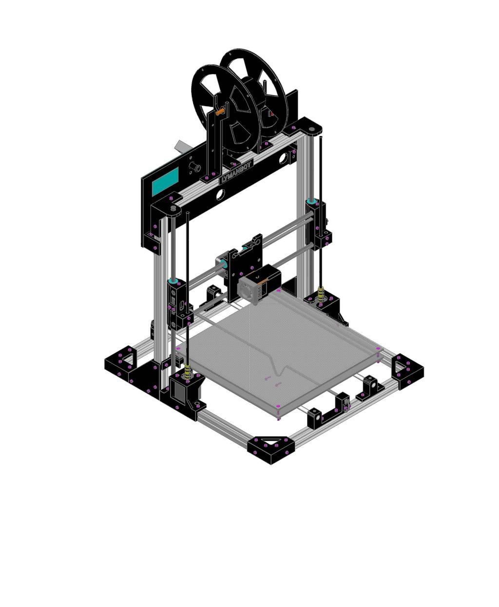
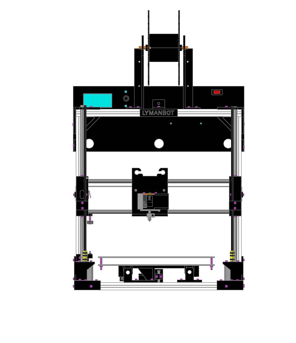
1 LYMANBOT 3D PRINTER V3 Construction Manual Page 1 Read this whole Manual before starting to construct this Printer. User excepts all liability for the use of this Manual and the construction of this Printer. Lyman is to be held harmless and Lyman excepts no liability. This is not a Toy. Copyright 016 HUGH LYMAN INVENTOR View of Geeetech MK8 extruder Front full view LymanBot 3D Printer V3 while printing The LYMANBOT 3D PRINTER has been conceived from the best features I liked of two Printer Kits, one fully assembled Printer, two sets of plans and a CNC Router. First I designed the Printer in solid model using the features I liked, then I used many parts from one ORD Kit Printer and constructed the first V1 LymanBot Printer. It worked so well I then did the same using parts from the factory assembled TAZ Printer and constructed the next V LymanBot Printer. FEATURES: 80 x 80 x 30mm (11x11x9 ) print area. Open design that allows for easy maintenance. Single Belt Drive System for both X & Y axis. 6mm Z axis threaded rods. 10mm shafts and bearings. Smart LCD controller with SD card. Overall size: 60 W x 500 D x 550mm H (w/o spool holder). 00 T slot aluminum framing. The LymanBot V3 3D Printer is an open source product licensed under: Creative Commons Attribution-Share Alike.0 International License. The following pages illustrates how I built the extruder.


2 Page This shows the V1 Printer, the first one constructed. It is printing padding press parts in black filament. It has a print area of 11 x 11 x 9. This shows the V Printer, the second one constructed. It is printing padding press parts in white filament. It has a print area of 11.5 x 11.5 x 10. Both these Printers are different from V3 and are operated with a Rambo Motherboard and a V power supply. Each features a Full Graphics LCD Controller. V1 Printer Hot Bed is powered with 110V Heater and V is powered with V Heater. The extruders are my own DIY units powered with stepper gear motors with fan cooling with an LED light. V3 printer is different and designed to make a less expensive printer. Read on for the details. Constructing the V3 LymanBot 3D Printer: Here is the frame assembled. All the aluminum T sections are 0 x 0mm and are all the exact same length of 0mm.


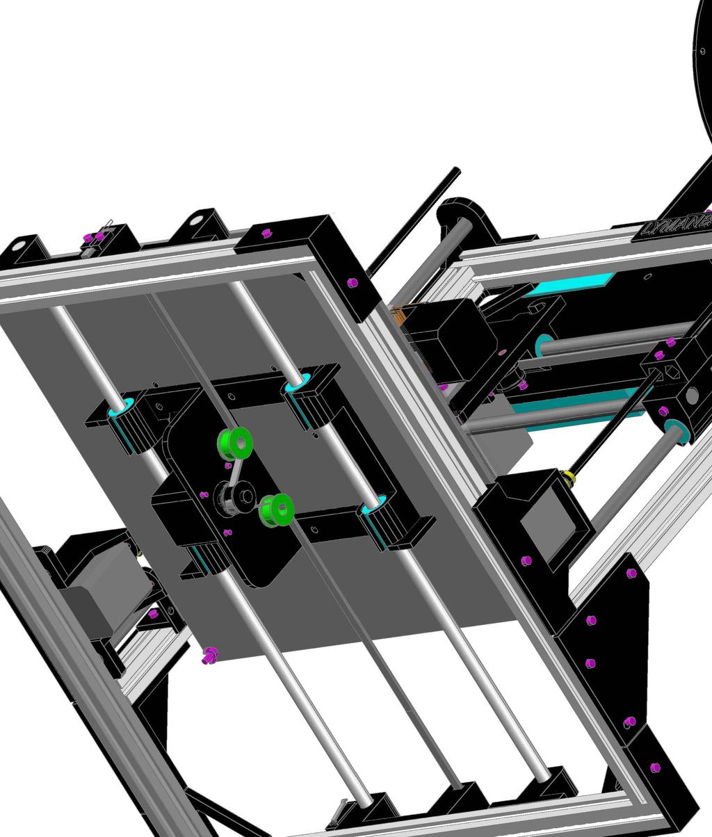
3 Page 3 Start with bottom of the frame. Note how the aluminum rails are aligned. The front of the frame is at the bottom of the picture. This makes the frame longer in depth by 0mm. All the tee nuts have to be inserted to each rail before attaching the corners parts. I usually inset an extra one just in case. It is terrible to assemble it and have to dissemble it to add one. Check that it is square when completed. Here the bottom of the frame is assembled. Note the tee nuts in the rails. Forget the lighter and the plastic screw driver, I can t remember what I used them for here. The frame is now 0mm wide and 60mm deep not including the cap screws. Now the vertical posts and the top rail are assembled. Here I used a dowel gauge to make sure the distance between the vertical rails at the bottom and the top are the same. The Y axis shaft brackets and the Z motor brackets are installed here. The Y axis brackets have been changed as you will see later. This is to make it easier to adjust. The position of the vertical post and the Z motor brackets is adjustable. This is to allow for getting the nozzle about 5mm off the bed when in the home position thus allowing extruding prior to printing.


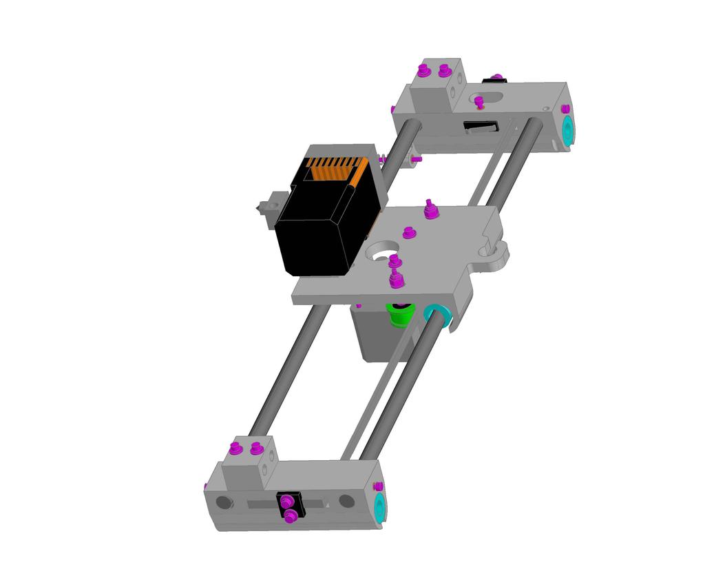
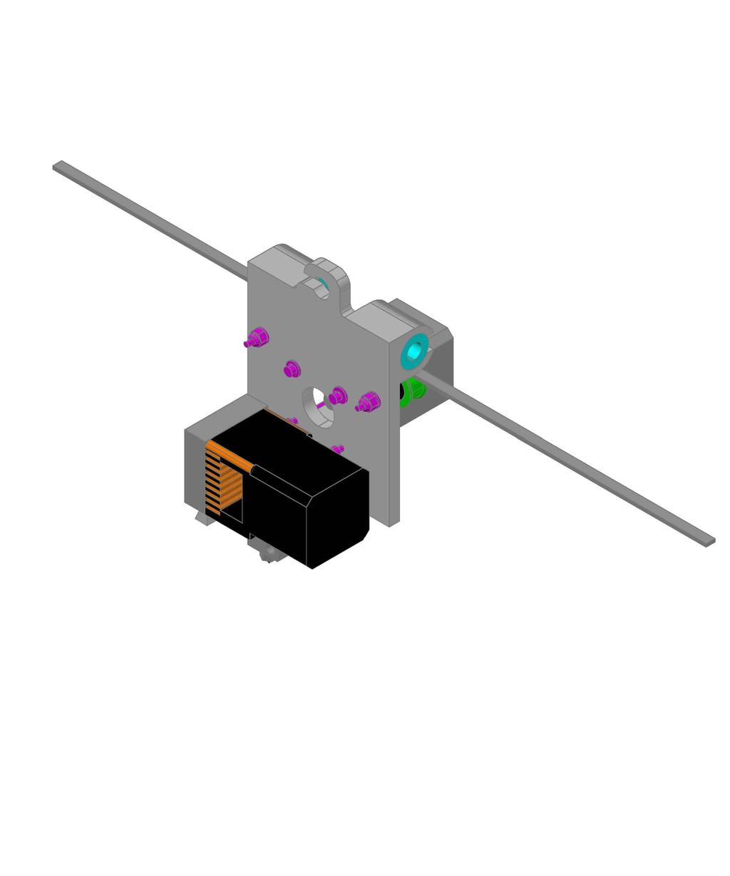
4 Page The Y axis shaft brackets are in two parts, one with the belt attachment arm and other for one shaft. Note there is a 3mm brass insert and 3mm set screw to secure the shaft. The shaft holes in the brackets have to be dressed so that the shaft fits to where it is snug, but can slide in the hole for assembling the Bed to the Frame. The drive belt arm on the Y axis has a slot for the belt attachment and the belt is secured with a clip and two 3mm cap screws. There are two 3mm brass inserts used to hold the belt clips. This assembly achieves easy belt adjustment. Note the single belt is a design used in my CNC Router. This picture shows the arrangement of the vertical post bracket and the Z motor mount bracket. Note the Z shaft end fits into a hole in the motor mount bracket. This bracket has this hole on each side, thus it is the same for the opposite shaft. Here the 6mm threaded rod is coupled to the step motor 5mm shaft with a 1/ clear flexible plastic tube. The motor shaft requires a sleeve for a snug fit. Zip ties are then used to secure the couplers to the shafts. Note that this is a design I liked as used on the TAZ 3D Printer. Zip ties holds the wire in the T slots of the posts. The loose wire is the one from the Z limit switch to the Ramps board and thus it flexes as the X carriage moves up and down.


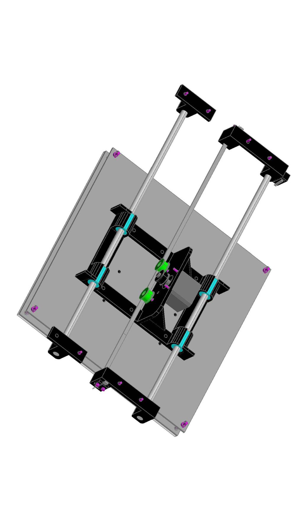
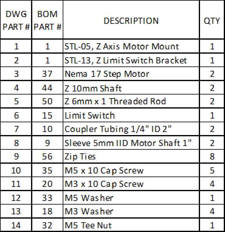
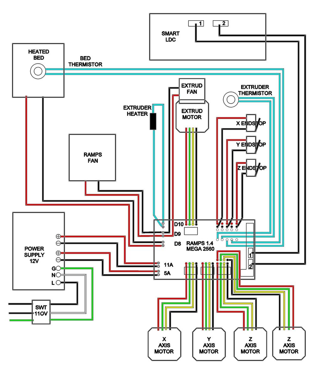
5 Page 5 I also use this little printed wire clips to hold the wires in the T slots, It is designed to also hold a sleeved set of wires. These may need dressing and they only turn one way. The print running at the time this picture was taken is 19% done and has been printing for 38 minutes. As the Thermistors used are HTC 3950 the Marlin table used does not indicate the correct temperature, so it is set to where it prints correctly. The bed heater being only 1V MKB PCB is slow to heat up and the 7 temp is not correct either. I used a digital thermometer to check the temps. I set the bed temp now at 8 and it holds 8 on the LCD. The Ramps 1. on a Mega 560 R3 is mounted with stand offs so wires can be run behind or tucked in. From past experiences I have found that if there is a problem it has always been a connection. Therefore I leave all the wires exposed for easier correction. Covers for the electronics is your option. If a motor skips a step the Driver must be adjusted. DO NOT ADJUST WITH ANY POWER ON or you will fry the driver as I did many times. The sticker in the Power Supply says CAUTION HIGH VOLTAGE, so remember that! Here the USB is disconnected as the Printer is running off the SD card. Note the X axis motor is mounted to the X carriage and that is the same for the Y carriage.


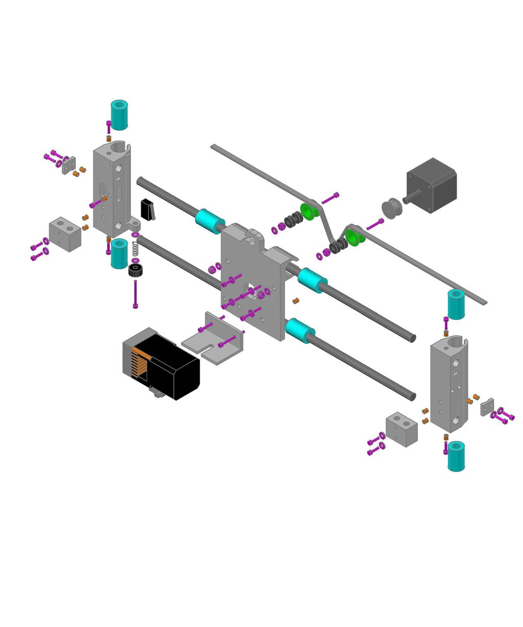
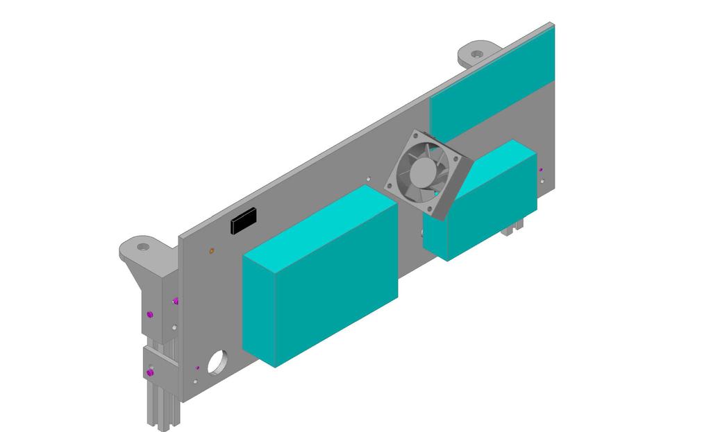
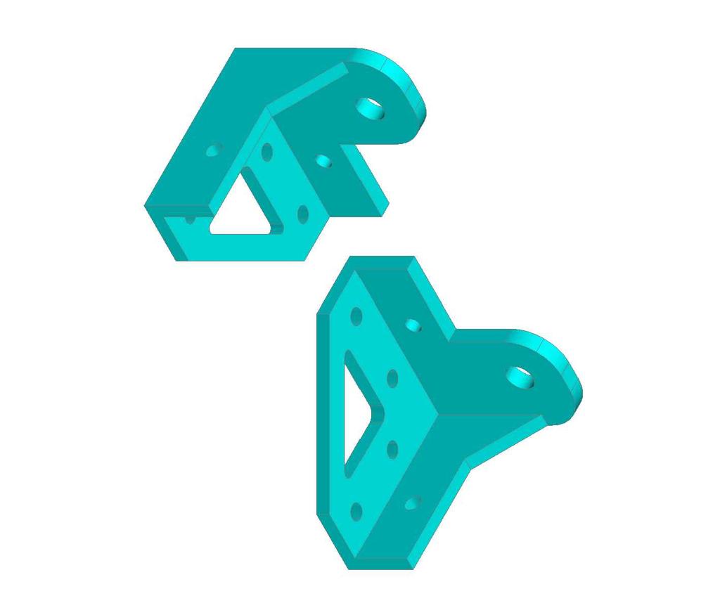
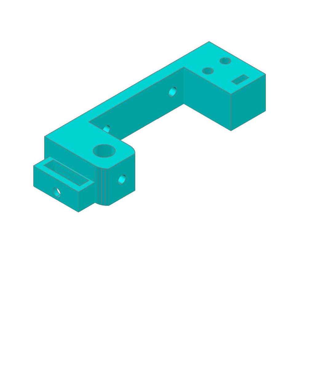
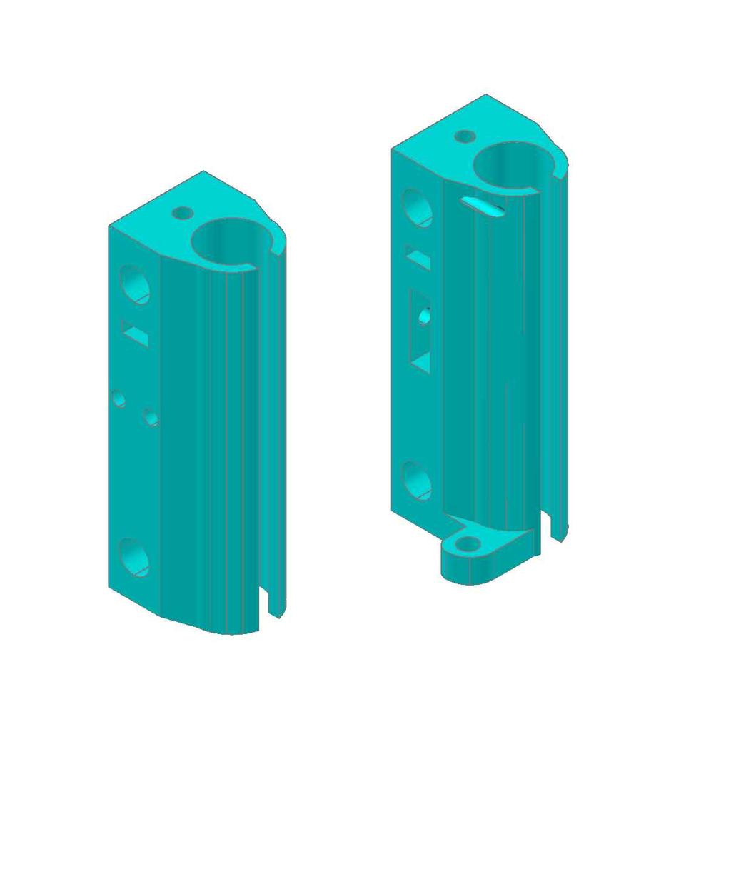
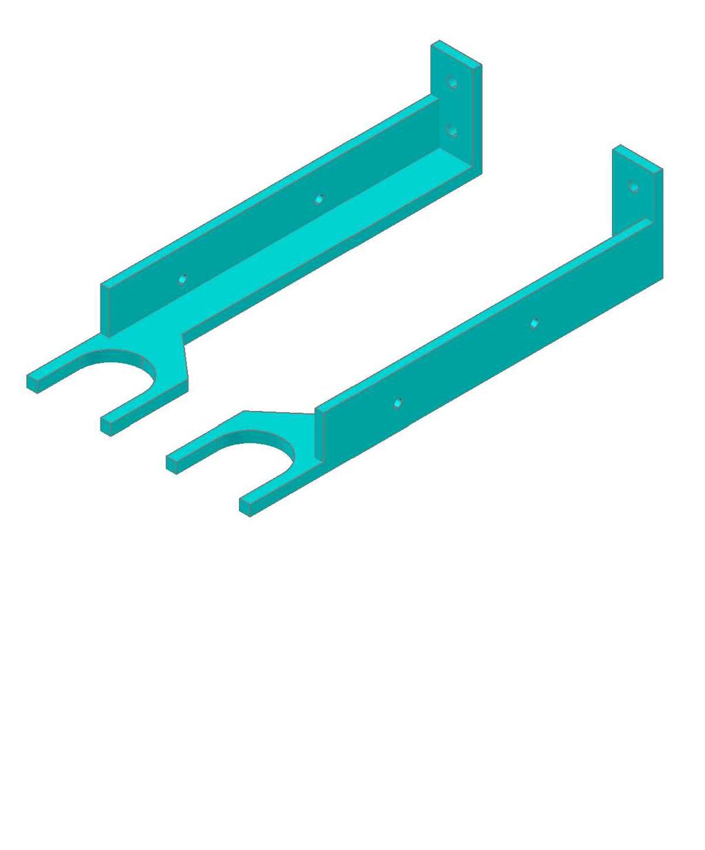
6 Page 6 This is the top left corner bracket that attaches the rails and holds the top of the 10mm Z shaft. There is a right and left hand bracket. Also visible is the angle bracket that holds the electronic panel and there are three of these. The electronic panel can be made from MDF, Plywood, Hardboard, Plexiglas or 3D printed in two pieces. The one here was 3D printed and the two parts cemented together with solvent cement. Here is a shot of the left Z carriage bracket with the X carriage limit switch installed. Note there is a hole for the limit switch wires at the top and a hole for a 3mm insert and set screw to hold the switch. To the bracket is mounted the Z rod bracket that contains a wobbly brass 6mm x1 nut. See drawings for exploded views. This picture shows the right XZ carriage bracket which only has the XZ rod bracket and shaft set screws. Each of the brackets have 10mm leaner bearings inserted. The brackets may need some dressing for the bearings to fit in snugly. This view shows the vertical post bracket and the Z motor mount bracket and their alignment. These can be adjusted to obtain the correct distance from the bed plate and aligning the vertical shaft with the vertical post. Here I also use a dowel as a gauge from the top to the bottom. Also visible is the Z limit switch bracket which is also adjustable. This view shows the back Y shaft brackets with the Y axis limit switch. Note here the belt is long enough to grip for adjusting. It is then tied with a zip tie to hold the loose end.


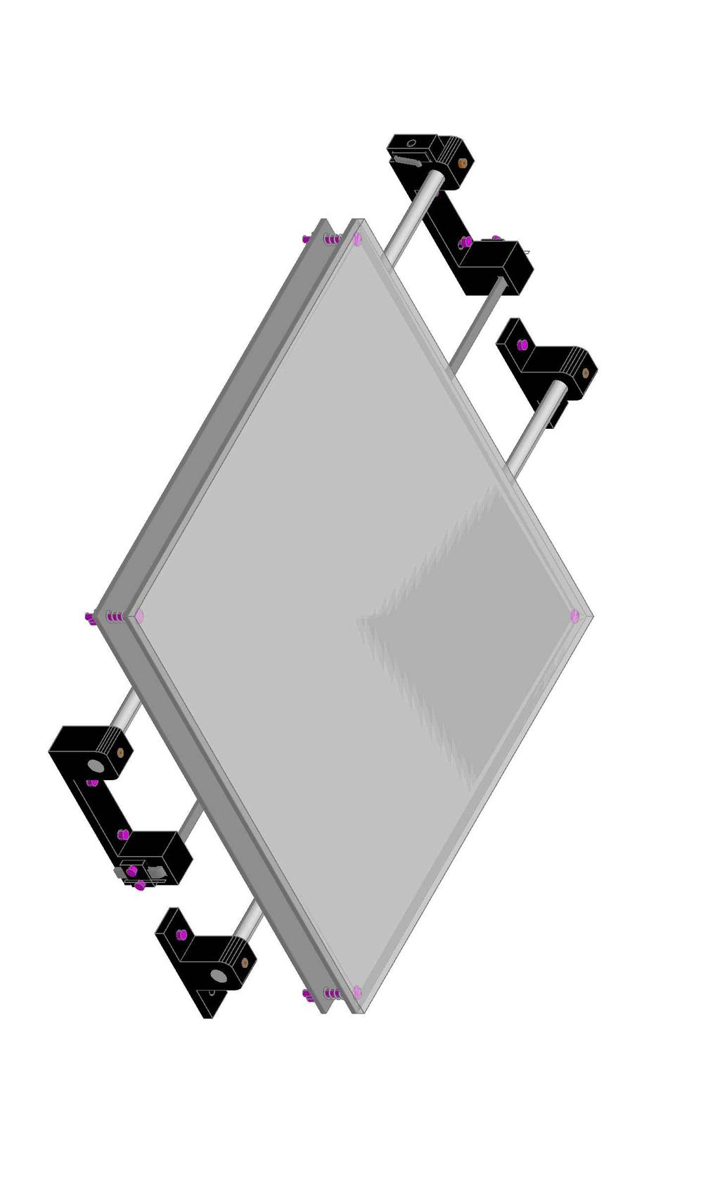
7 Page 7 This back view of the X axis carriage shows the stepper motor mounted. Note the two top idler pulleys and the belt which goes over the top and down under the drive pulley mounted on the motor shaft. Before installing the belt make sure the carriage glides smooth and easy on the shafts. You should be able to push it with a finger and it should glide the full length of the travel distance. This is a view of the X carriage from the back. The two idler pulleys each have two bearing inserted and are attached with mm cap screws in brass inserts. Disregard the two visible brass inserts as they were for mounting a different DIY hot end. The bed consists of two 1/8 x 1 x 1 aluminum plates with a 3/16 x 1 x 1 tempered glass that is held in place with paper clips. See the exploded view drawing for the construction. The Y bearing bracket is attached to the bottom plate with 6 M cap screws. The top plate is mounted to the bottom plate with #10-3 FHS, #10-3 hex nuts and #10-3 thumb screws, washers with 1 x 5/16 springs. The BOM shows these in metric sizes. The heater pad is screwed to the top plate after drilling holes and taping them for M3x6mm cap screws. Make sure the screw does not protrude above the top face of the plate. Use washers if needed. The Tap Handle is printed with Lyman Filament. The wires here have to be soldered on the 1V terminals and the thermistor installed. I use kapton tap to secure the thermistor.


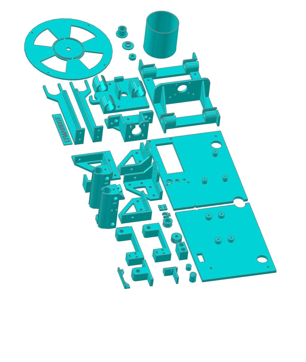
8 Page 8 This is the Z axis threaded rod clip that connects to the Z bearing bracket that controls the vertical movement of the hotend. The bottom has hex holes part way up and a round hole on the top (not shown). I thread the 6mm brass nut on the end of the rod and heat it with a butane torch. Then it is pressed into one of the holes to the end of the hex hole and then wobbled a little till it cools. The looseness allows for self alignment as the rods turn. The second hole is only it you screw up, you can try again. OK, it is done and calibrated, so now test it. First test print. 0 x 0 x 0mm test box Second test print. Aphrodite from Thingiverse Third test print. Twisted Vase Basic from Thingiverse A full set of V3 printed parts from this V3 Printer. Sliced with perimeters and 50% infill, Weight = 1.76 lbs Note: I wrap a pipe cleaner around the filament which cleans off any dust on the filament as this is DIY extruded filament from the Lyman Extruder V6. Now study the drawings and BOM before ordering or constructing
9 Page 9
10 Page 10
11 Page 11
12 Page 1
13 Page 13
14 Page 1
15 Page 15
16 Page
17 Page 17

18 Page
19 Page

20 Page NOT SHOWN 8 5 6
21 Page 1
22 Page
23 Page
24 Page
25 Page
26 Page
27 Page 7
28 Page 8
29 Page 9

30 Page
31 Page 31
32 Page
33 Page 33

34 Page 3


35 Page
36 Page 36

37 Page


38 Page
39 Page 39


40 Page 0

41 Page 1


42 Page


43 Page 3

44 Page
45 Page 5
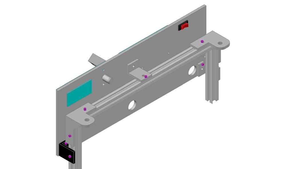
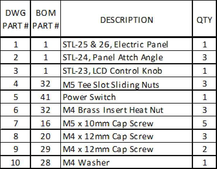
46 Page 6 BOM PART # DESCRIPTION UNIT QTY LYMANBOT 3D PRINTER V3 BOM FOB UNIT PRICE SUB TOTAL SUPPLIER SUPPLIER PART # 1 ABS or PLA Filament LBS $3.00 $1.00 Your choice Pellets If you extrude your own filament Alum Angle Extruder Mount EA 1 $3.00 $3.00 Online Metals 3 Aluminum Plate 1x1x1/8" EA $15.00 $30.00 metalremnantsinc ebay Aluminum T Slot Rails 0x0mm EA 7 $5.00 $35.00 Misumi HF Bearing 13 x 5 x mm ID EA 8 $0.55 $.0 ebay 6 Bearing Linear 10mm ID EA 11 $1.0 $13.0 jamesbondtb ebay 7 Bed Heater EA 1 $15.00 $ dp_champion ebay 8 Belt Timing w/ drive pulleys EA 1 $1.00 $1.00 3dp_champion ebay 9 Coupler Sleeve 5mm ID x 5mm EA $0.10 $0.0 hardware store 10 Coupler Tubing 1/" ID " EA $0.0 $0.0 hardware store Z motor couplers 11 Fan 60mm EA 1 $5.00 $5.00 3dp_champion ebay 1 Geeetech MK8 Extruder EA 1 $36.00 $36.00 efind0813 ebay 13 Glass Tempered 1x1x3/16" EA 1 $7.5 $7.5 Store Supply sales@storesupply.com 1 Kapton Tape FT $0.10 $0.0 3dp_champion ebay 15 Limit Switch EA 3 $1.75 $5.5 UltiMachine 16 M3 Brass Heat Insert Nut EA 1 $0.13 $1.56 McMaster Carr 9180A M3 Set Screw EA $0.10 $0.0 Fastenal 18 M3 Washer EA $0.0 $0.88 Fastenal 19 M3 x 30mm Cap Screw EA $0.7 $0.5 Fastenal 0 M3 x 10mm Cap Screw EA 16 $0.17 $.7 Fastenal M3 x 0mm Cap Screw EA 6 $0. $1.3 Fastenal M3 x 5mm Cap Screw EA $0.5 $1.00 Fastenal M3 x 0mm Cap Screw EA 3 $0.8 $0.8 Fastenal M3 x 5mm Cap Screw EA $0.30 $1.0 Fastenal M3 x 6mm Cap Screw EA $0.17 $0.68 Fastenal M3 Nylock Hex Nut EA 6 $0.10 $0.60 Fastenal 7 M Nylock Hex Nut EA 6 $0.15 $0.90 Fastenal 8 M Washer EA 8 $0.05 $0.0 Fastenal 9 M x 1mm Cap Screw EA $0.0 $0.0 Fastenal 30 M x 30mm Cap Screw EA $0.5 $1.00 Fastenal 31 M5 Hex Nut EA $0.10 $0.0 Fastenal 3 M5 Tee Sliding Nut EA 65 $0.50 $3.50 Misumi 33 M5 Washer EA 8 $0.05 $0.0 Fastenal 3 M5 Wing Nut EA $0.50 $.00 hardware store 35 M5 x 10mm Cap Screw EA 65 $0.5 $16.5 Fastenal 36 M5 x 0mm FHS EA $0.50 $.00 Fastenal 37 Motor Stepper Neama 17, 5.5 KG CM EA $16.00 $6.00 biowavescom ebay 38 Power Cable EA 1 $1.5 $1.5 blairtg ebay 39 Power Cable Clip EA 1 $0.15 $0.15 hardware store 0 Power Supply 1V EA 1 $9.00 $9.00 eshopping080 ebay 1 Power Switch EA 1 $1.00 $1.00 Electric Goldmine illuminated Ramps Mega 560 EA 1 $8.00 $8.00 AliExpress Mega 560, Ramps 1., motor drivers 3 Screws Misc EA 5 $0.0 $1.00 hardware store Shaft 10mm 0mm long EA $9.00 $18.00 mysupertop ebay 5 Shaft 10mm x 50mm EA $9.00 $18.00 mysupertop ebay 6 Shaft 10mm x 80mm EA $9.00 $18.00 mysupertop ebay NOTES
47 Page 7 7 Smart LCD Controler EA 1 $13.00 $13.00 leap3d ebay 8 Spring 1 x 1/" Z limit knob EA 1 $0.50 $0.50 McMaster Carr 9657K8 9 Springs Hot Bed 1.5x5/16" EA $0.50 $.00 McMaster Carr 9657K Threaded Rod 6mm x 300mm (1") EA $6.00 $1.00 McMaster Carr 9335A TTT (This That & The Other) LOT 1 $5.00 $ USB Cable EA 1 $3.00 $3.00 ebay 53 Wire ga LOT 1 $5.00 $ Wood Dowel 10x160mm (3/8"x6 1/" EA 1 $0.50 $0.50 hardware store 55 Connectosr Misc LOT 1 $5.00 $ Zip Ties 100mm EA $0.05 $1.0 ebay 57 Zip Ties 150mm EA 16 $0.05 $0.80 ebay 58 M Brass Heat Insert Nut EA $0.15 $0.30 McMaster Carr These are for mounting the Aluminum Angle SUB TOTAL COST $53.9 ESTIMATED FRT 10.00% $5.33 This list is what I used but you can TOTAL COST $98.6 use other suppliers as you want.
Kossel Rev B Build Guide V1.0
 Kossel Rev B Build Guide V1.0 1 Table of Contents: Step 1: BASE ASSEMBLY Gathering parts: Building the Corners and Base: Step 2: UPPER ASSEMBLY Building Upper: Step 3: VERTICAL RAIL INSTALLATION Building
V4 Premium Kit. Prusa i3 Build Guide
 V4 Premium Kit Prusa i3 Build Guide Hi! Congratulations on your purchase of the DIYElectronics.co.za Prusa I3 kit, the best South African 3D Printer Kit! Hopefully this should serve as complete guide to
Delta Rostock mini G2& G2s Building instruction
 Delta Rostock mini G2& G2s Building instruction Safety Instructions ShenZhen GETECH CO.,LTD Building the printer will require a certain amount of physical dexterity, common sense and a thorough understanding
Part 7 Assembling the X axis
 Part 7 Assembling the X axis 1 2 The X axis is a key part of the printer, it carries the extruder on a carriage that moves the extruder laterally in the X axis. The x axis itself is moved vertically on
Geeetech Delta Rostock mini G2 pro / G2s pro Building Instruction
 Geeetech Delta Rostock mini G2 pro / G2s pro Building Instruction (Document version: 04-11, 2016) CONTENT Safety Instructions... 1 Preparation... 2 1 Base Assembly... 3 1.1 Motor holder assembly... 3 1.2
Code Product Qty 1 Top Vertex 3 2 Hot End Housing 1 3 Bottom Vertex 3 4 Print Platform Lock 3 5 End Stop Holder 3 6 Filament Feeder Motor Bracket 1 7
 List of Parts Code Product Qty 1 680mm Extrusion 3 2 Power Supply 1 3 240mm Extrusion 9 4 42mm Nema 17 Stepper Motor 3 5 Slider-Hotend Connecting Rod 6 6 48mm Nema 17 Stepper Motor 1 7 Linear Rail with
(Assembling Guide supplied by imakr ) with the support of MyMiniFactory.com
 with the support of MyMiniFactory.com") (Assembling Guide supplied by imakr ) with the support of MyMiniFactory.com Summary Congratulations on beginning on your journey into 3D printing with the STARTT 3D printer. In this guide, you will have
(Assembling Guide supplied by imakr ) with the support of MyMiniFactory.com Summary Congratulations on beginning on your journey into 3D printing with the STARTT 3D printer. In this guide, you will have
Assemble Instruction of Geeetech Acrylic. Prusa I3 Pro C
 Assemble Instruction of Geeetech Acrylic Prusa I3 Pro C Version 04-11-2016 Safety Instructions Building the printer will require a certain amount of physical dexterity, common sense and a thorough understanding
Assemble Instruction of Geeetech Acrylic Prusa I3. Pro & pro B
 Assemble Instruction of Geeetech Acrylic Prusa I3 Pro & pro B Version 04-11-2016 Safety Instructions Shenzhen GETECH CO.,LTD Building the printer will require a certain amount of physical dexterity, common
Assemble Instruction of Geeetech Acrylic Prusa I3. pro C
 Assemble Instruction of Geeetech Acrylic Prusa I3 pro C Safety Instructions Shenzhen GETECH CO.,LTD Building the printer will require a certain amount of physical dexterity, common sense and a thorough
M2 Assembly. M2 Sub-Assemblies mm Belt Sub-Assembly mm Belt Sub-Assembly Spider Sub-Assembly... 4
 M2 Assembly Table of Contents M2 Sub-Assemblies... 3 630mm Belt Sub-Assembly... 3 702mm Belt Sub-Assembly... 3 Spider Sub-Assembly... 4 Idler Bolt Sub-Assembly... 8 Y Motor Sub-Assembly... 9 X Motor Sub-Assembly...
AM8 Printer A metal frame for your Anet A8 By Pheneeny v1.0 April 20, 2017
 AM8 Printer A metal frame for your Anet A8 By Pheneeny v1.0 April 20, 2017 Please read this entire document before printing parts or building this frame Disclaimer: This guide is for informational purposes
Step 1 Assemble Base Frame Parts: 2040 Aluminium profile 250mm 1pcs Base Plate 1pcs M4-8mm screw 3pcs M4 T-Nut 3pcs
 Step 1 Assemble Base Frame 2040 Aluminium profile 250mm 1pcs Base Plate 1pcs M4-8mm screw 3pcs M4 T-Nut 3pcs Put the aluminium profile on the base plate, secure them with 3pcs M4-10mm screws & T-Nut Step
The Portable Open Source 3D Printer
 http://web.archive.org/web/201502142011/http://www.tantillus.org/build_3.html Page 1 of 12 captures 12 Oct 12 - Feb 15 The Portable Open Source 3D Printer Home Start Case X/Y Axis Extruder Z Axis Electronics
5. Extruder Assembly
 5. Extruder Assembly Guide for the assembly of the Extruder. Written By: Josef Prusa 2017 manual.prusa3d.com Page 1 of 22 Step 1 Get the necessary tools 2.5 and 1.5 mm Allen key Needle-nose pliers Step
INVENT3D Printer Kit Disassembly Instructions
 INVENT3D Printer Kit Disassembly Instructions Version 6 AST2 10/26/16 1 I. General Disassembly Instructions Use the case layer drawings to ensure that components are stored in the appropriate location
Step 1 Assemble Base Frame
 Step 1 Assemble Base Frame Parts: 2040 Aluminium profile 250mm 1pcs Base Plate 1pcs M4-8mm screw 3pcs M4 T-Nut 3pcs Put the aluminium profile on the base plate, secure them with 3pcs M4-10mm screws & T-Nut
Assembly Instructions. Beta Prusa DualX 3D Printer
 Assembly Instructions Beta Prusa DualX 3D Printer Version 2.6 Date Page 1 / 72 General data about the assembly instructions for an incomplete machine according to appendix VI of the EG machinery directive
Assembly Instructions Beta Prusa Standard & Deluxe
 Assembly Instructions Beta Prusa Standard & Deluxe 3D Printer Version 2.6 Date Page 1 / 67 General data about the assembly instructions for an incomplete machine according to appendix VI of the EG machinery
0. Disassembly. Disassembly of the MK2 printer and upgrading to the MK2S using the upgrade kit. Written By: Jakub Dolezal
 0. Disassembly Disassembly of the MK2 printer and upgrading to the MK2S using the upgrade kit. Written By: Jakub Dolezal 2018 manual.prusa3d.com/ Page 1 of 12 Step 1 Preparing the printer Ensure the printer
BIGBOT ASSEMBLY INSTRUCTIONS. 1/18/2017 V0.5
 BIGBOT ASSEMBLY INSTRUCTIONS www.bigbot-3d.com 1/18/2017 V0.5 FOREWORD: PLEASE TAKE CARE WHEN HANDLING THE GANTRY. THE ASSEMBLY SHOULD BE HANDLED ONLY BY THE ALUMINUM FRAME, AND AVOID TOUCHING OR LIFTING
Assembly Instructions
 Assembly Instructions Note: Prior to assembly, be sure to remove all printing pads from the printed parts and also be sure to sort through and organize all of your hardware before assembly this will help
Assembly Guide for Printrbot - Simple Maker s Edition 1405
 Assembly Guide for Printrbot - Simple Maker s Edition 1405 Last update: March 2016 Please Note: be careful on the steps that are underlined 1 Contents Tools Needed:... 3 First step: Check components and
Printrbot Simple (Model 1403) Rev F Printrboard
 Rev F Printrboard") Printrbot Simple (Model 1403) Rev F Printrboard Printrbot Simple is currently shipping with the Rev F Printrboard. Check which rev Printrboard your Simple kit includes and use the corresponding instructions.
Printrbot Simple (Model 1403) Rev F Printrboard Printrbot Simple is currently shipping with the Rev F Printrboard. Check which rev Printrboard your Simple kit includes and use the corresponding instructions.
Shenzhen GETECH CO.,LTD GEEETECH. Building Instructions of Geeetech Prusa I3 X
 Building Instructions of Geeetech Prusa I3 X CONTENT CONTENT... 2 Safety Instructions...3 Preparation...4 Unfold the box and check the package list... 5 1. Assemble the threaded rods of Y axis... 6 2.
Legacy Woodworking Machinery a division of Phantom Engineering. The Legacy CNC. Assembly Manual
 Legacy Woodworking Machinery a division of Phantom Engineering The Legacy CNC Assembly Manual New Orientation of the Legacy Step one: Re-orientation of the machine Remove the X-axis screw and supports.
Assembly Instructions
 Assembly Instructions Note: Prior to assembly, be sure to remove all printing pads from the printed parts and also be sure to sort through and organize all of your hardware before assembly this will help
Assembly Instructions Beta Prusa Standard & Deluxe
 13/11/12 Assembly Instructions Beta Prusa Standard & Deluxe 3D Printer Version 1.0 Date 13/11/12 Page 1 / 66 General data about the assembly instructions for an incomplete machine according to appendix
IMPORTANT SAFETY INSTRUCTIONS
 ASSEMBLY MANUAL IMPORTANT SAFETY INSTRUCTIONS! WARNING SHARP EDGES Use caution during assembly and operation of the 3D printer to ensure no sharp edges will cut you. Inspect the printer for any damage
Written By: Brook Drumm
 Simple 1401 Assembly For kits produced between 1/15/14-6/1/14. This guide is for kits with the Fan Shroud. Instructions for metal and wood extruder (and bed) included below. Written By: Brook Drumm TOOLS:
Geeetech Acrylic I3 Pro C 3D Printer
 Geeetech Acrylic I3 Pro C 3D Printer Copyright Declaration The copyright of this manual belongs to the Shenzhen GETECH CO., LTD. (hereinafter referred to as the "Geeetech"), and all rights reserved. No
Parts & Tools. O'Cello printing and assembly instructions. o-cello.com
 The O'Cello is a 3D-printable cello developed by Conor O'Kane, which is free to download and print for personal use. This document will show you how to print and assemble your own O'Cello. For the latest
Document version: 1.1. Beagle Build manual
 Document version: 1.1 Beagle Build manual TABLE OF CONTENTS Table of contents...2 About the Beagle...3 Change history...4 Safety warnings...4 Required tools...5 1. Bars & Printed parts examination...6
Welcome! Table of Contents
 Welcome! The folks at Random Idea Generator Shop would like to thank you for purchasing our 3D printer kit. We are dedicated to providing an easy to build kit with customizable options to meet your requirements.
SeeMeCNC Guides. Rostock Max v1/v2 HE280 Hotend Upgrade. This How-to Guide will walk you through the steps of upgrading to the HE280 Hotend.
 SeeMeCNC Guides Rostock Max v1/v2 HE280 Hotend Upgrade This How-to Guide will walk you through the steps of upgrading to the HE280 Hotend. Written By: SeeMeCNC 2018 seemecnc.dozuki.com/ Page 1 of 33 Step
Geeetech A30 3D Printer Building Instruction
 Geeetech A30 3D Printer Building Instruction Contents Safety Instructions... 1 Preparation... 2 1. Unfold the Box and Check the Package... 3 2. Assembly... 4 3. Wiring... 9 4. Warm Tips...16 Safety Instructions
ABM International, Inc. Navigator Assembly Manual
 ABM International, Inc. 1 1.0: Parts List Tablet (Qty. 1) Tablet mount (Qty. 1) NOTE: Mount may appear and operate different then image below Control Box (Qty. 1) Motor Power Supply (Qty. 1) 2 X-axis motor
F400 QUICK-START GUIDE
 F400 QUICK-START GUIDE PLEASE READ THIS DOCUMENT BEFORE OPERATING YOUR PRINTER Revision 10-1/31/18 Page 1 Table of Contents 1. Introduction... 3 2. What s in the Box... 3 3. Unboxing Your F400... 4 4.
re3d Assembling Gigabot: "Flatpack"
 re3d Assembling Gigabot: "Flatpack" Your Gigabot was assembled, calibrated, tested, and taken apart for shipping purposes. All you need to do is reassemble it, and you're ready to go! Written By: Chris
Ender-3 3D Printer. Instructions for assembly
 Ender-3 3D Printer Instructions for assembly This guide is for the Ender-3 3D printer. Select the correct input voltage to match your local mains (220V or 110V). Because of software/hardware upgrades and
Goal: Provide a visual guide of the steps needed to construct a Romscraj Extruder.
 V.0 (0 Jul 202) Document Version & Date: V.0 0 Jul 202 Goal: Provide a visual guide of the steps needed to construct a Romscraj Extruder. Original Authors: Md Noh design of the Romscraj Extruder Special
Shapeoko XXL Assembly Guide
 Shapeoko XXL Assembly Guide 04/27/2016 XXL Packing LIst Item Qty Description Y-Carriage (left) 1 Y-Carriage (right) 1 X/Z Assembly 1 40 Rail 3 1 rail has mounting holes for controller Wasteboard Half 2
Note: This assembly instruction will cover all configurations of Alloy adjustable height double bases.
 Note: This assembly instruction will cover all configurations of adjustable height double bases. 1 Screw in the provided adjustable glides into each leg as shown in Figure A. Two glides per leg. Figure
SatNOGS. SatNOGS Rotator v3 Mechanical Assembly. This is the assembly guide for the third version of the SatNOGS Rotator.
 SatNOGS SatNOGS Rotator v3 Mechanical Assembly This is the assembly guide for the third version of the SatNOGS Rotator. Written By: Pierros Papadeas 2017 satnogs.dozuki.com Page 1 of 19 INTRODUCTION Notes:
TVRR Prusa. Visual Assembly Guide
 TVRR Prusa Visual Assembly Guide November 2013 Copyright November 2013, David Price All sections are distributed under the Creative Commons Non Commercial Share Alike Attribution 3.0 license, which permits
MatterHackers. How to Install an E3D v6 HotEnd on a Lulzbot. Upgrade your TAZ with a shiny new E3D hotend. Written By: Ryan Lutz
 MatterHackers How to Install an E3D v6 HotEnd on a Lulzbot TAZ 5 Upgrade your TAZ with a shiny new E3D hotend. Written By: Ryan Lutz 2017 matterhackers.dozuki.com Page 1 of 21 INTRODUCTION NOTE: This guide
Taz 6 Enclosure. Taz 6 Enclosure 2017 Version 2.1 Page 1 of 12
 Taz 6 Enclosure This work is licensed under a Creative Commons Attribution-ShareAlike 4.0 International License. Created by David Randolph and printedsolid.com Taz 6 Enclosure 2017 Version 2.1 Page 1 of
Heacent 3D printer assembly manual. Prusa i3
 Heacent 3D printer assembly manual Prusa i3 Y-axis assembly 1. Y axis motor section: Find the belowing parts bag, Y-axis motor Assembled parts are separated as shown below, note that the motor between
Table of Contents CONTENTS
 Table of Contents CONTENTS Introduction... 2 Contact TKI... 2 Printer Features & Definitions... 3 Software Parameter Setup... 8 Setting Up A Printer Profile in Cura... 8 Printing Settings... 13 Printing
This manual will aid in the assembly of the FireBall V90 and FireBall X90. The assembly of both machines will be identical, unless specified.
 This manual will aid in the assembly of the FireBall V90 and FireBall X90. The assembly of both machines will be identical, unless specified. Step #1 Lay all parts out to verify quantities. (2) 2 x 25-1/4
Titan Aero Assembly. Titan Aero Assembly. Learn to assemble your Titan Aero. Written By: Gabe S e3d-online.dozuki.
 Titan Aero Assembly Learn to assemble your Titan Aero Written By: Gabe S. 2018 e3d-online.dozuki.com/ Page 1 of 26 INTRODUCTION The Titan Aero is a very similar build to a Titan and a V6 put together (which
Classification Of Screws
 Classification Of Screws M3 nuts 60pcs M3*20mm screws 58pcs M2.5*10mm black screws 2pcs M8 nuts 12pcs M3*10mm screws 17pcs M3*30mm screws 7pcs M8 Cushion ring 12pcs M3*14mm screws 4pcs Plastic Pillars
3. X-axis assembly. 3. X-axis assembly. Written By: Jakub Dolezal manual.prusa3d.com/ Page 1 of 13
 3. X-axis assembly Written By: Jakub Dolezal 2018 manual.prusa3d.com/ Page 1 of 13 Step 1 Tools necessary for this chapter Needle-nose pliers for zip tie trimming. 2.5mm Allen key for M3 screws 2mm Allen
400A 40113V, 401A 40120V, & 401AL 40120VL ALUMINUM VERTICAL 4000 LB LIFT INCLUDES SCREW LEG ASSEMBLY INSTRUCTIONS
 12/11/07 PAGE 1 OF 12 400A 40113V, 401A 40120V, & 401AL 40120VL ALUMINUM VERTICAL 4000 LB LIFT INCLUDES SCREW LEG ASSEMBLY INSTRUCTIONS Thank you for purchasing our product! *Please read these instructions
CNC Router Parts PRO Machine Kit Cable Track Installation Instructions
 1 1 X CABLE TRACK TRAYS & BRACKETS The cable track on the side of the system is supported by a metal tray (or multiple trays for longer systems such as a PRO4896). These trays hang from brackets on the
imove-f Assembly Manual (Motorized Version-M1/M2)
") imove-f Assembly Manual (Motorized Version-M1/M2) 2 Table of Contents Exploded Desk Diagram Hardward & Tools Section 1: Basic Assembly of Desk Shipped KD (knock down) 3 4 5 Section 2: Attaching the Lowboard/Pedestal
imove-f Assembly Manual (Motorized Version-M1/M2) 2 Table of Contents Exploded Desk Diagram Hardward & Tools Section 1: Basic Assembly of Desk Shipped KD (knock down) 3 4 5 Section 2: Attaching the Lowboard/Pedestal
WASP Extended Shuttle Fitting. Process Overview
 Process Overview Tools needed; metric Hex key set Remove Wasp Plate sealer from all power and pneumatic supplies; situate the unit on a clear work area for access. Ensure the Wasp plate sealer has cooled
INSTALLATION MANUAL FRONT. See pages 2 and 3 of this manual for configuration options. Level of Difficulty. Product Photo (center section only)
") INSTALLATION MANUAL FRONT Level of Difficulty Moderate Product Photo (center section only) All hardware listed below will be provided with the bumpers center section. Additional hardware will be supplied
INSTALLATION MANUAL FRONT Level of Difficulty Moderate Product Photo (center section only) All hardware listed below will be provided with the bumpers center section. Additional hardware will be supplied
OX CNC. Mechanical Assembly Instructions. S.A. Brown & Maker Store
 OX CNC Mechanical Assembly Instructions S.A. Brown & Maker Store v1.2 07 2017 Contents About The Maker Store Ox CNC Kit... 2 Unpack and Check All Components... 2 Tools Required... 2 Pre-Assembly Notes...
F410 QUICK-START GUIDE
 F410 QUICK-START GUIDE PLEASE READ THIS DOCUMENT BEFORE OPERATING YOUR PRINTER Revision 3-5/4/18 Page 1 1. Table of Contents 1. Table of Contents... 2 1. Introduction & Getting Support... 3 2. What s in
INSTALLING YOUR NEW SPRING LIFT ARM KIT
 INSTALLING YOUR NEW SPRING LIFT ARM KIT 1. Measure the distance that the roof is to be raised. [If your lift system is completely non-functional, you will need to calculate or estimate this distance as
Customers should turn off the machine with the power cable and USB data cable pulled down from it when installing or removing extruder.
 INSTALLATION &REMOVAL of the EXTURDER Customers should turn off the machine with the power cable and USB data cable pulled down from it when installing or removing extruder. I.How to disassemble the extruder
Page 1. SureMotion Quick-Start Guide: LACPACC_QS 1st Edition - Revision A 03/15/16
 R K C T I Repair Kit Product Compatibility Repair Kit # Linear Actuator Assembly # LACPACC-002 LACPACC-003 LACP-16TxxLP5 (0.5-in lead screw pitch) LACP-16TxxL1 (1-in lead screw pitch) C P I R K 4 ea Flanged
Lead Screw Upgrade. How to upgrade your ROBO R1 to the new Lead Screw Upgrade Pack. Written By: Harrison Team RoBo 3D
 Lead Screw Upgrade How to upgrade your ROBO R1 to the new Lead Screw Upgrade Pack. Written By: Harrison Team RoBo 3D 2017 guide.robo3d.com Page 1 of 14 Step 1 Lead Screw Upgrade Begin by powering off and
ASSEMBLY & INSTALLATION INSTRUCTIONS
 ASSEMBLY & INSTALLATION INSTRUCTIONS VEHICLE MOUNT KIT 118 AND VEHICLE CENTER MEMBER 6050 TO FIT 2008 & LATER FORD F250-F550 4X4 Sno-Way, Down Pressure and EIS are registered trademarks of Sno-Way International,
40670 Transit Connect/NV200/City Express/ProMaster City Partition
 40670 Transit Connect/NV200/City Express/ProMaster City Partition Top Panel (1) Bottom Panel (1) Transit Connect (2014) Top Angle (1) TC Top MNT BRKT (2) TC Bottom MNT PLT (2) NV200/City Express Top Mount
CNC Router Parts. Standard Rack & Pinion Drive Assembly Instructions
 CNC Router Parts Standard Rack & Pinion Drive Tools List The following tools will be used for assembly and installation of the Standard Rack & Pinion Drive: Imperial Allen Wrench Set - 3/32", 5/32", 3/16",
Droplit v2 Frame Assembly
 SeeMeCNC Guides Droplit v2 Frame Assembly Droplit v2 Frame Assembly Written By: JJ Johnson 2017 seemecnc.dozuki.com Page 1 of 22 Step 1 Droplit v2 Frame Assembly Locate the Projector Plate, Projector Joining
Nancy s Knit Knacks LLC 4 Yard Option Upgrade Kit Assembly Instructions and User Manual
 Nancy s Knit Knacks LLC 4 Yard Option Upgrade Kit Assembly Instructions and User Manual Thank you for purchasing our 4 Yard Option (4YO) Upgrade Kit. To install this upgrade you are simply going to assemble
SE5a Instrument Board part 2 - rev 1.1
 SE5a Instrument Board part 2 - rev 1.1 Fuel (Petrol) Valve This valve uses two circular name plates, eight brass screws, one black plastic base, copper wire and two black plastic risers. You can pick any
E3 CNC Router Assembly Instructions
 E3 CNC Router Assembly Instructions Specifications... 3 Getting Started... 3 Safety First... 3 Required Tools... 4 Building the E3 CNC Engraver... 4 1. Z Spindle Mount Assembly... 5 3. Frame Assembly...
Side Winder R o u t e r L i f t.
 Woodpeckers PRECISION WOODWORKING TOOLS Side Winder R o u t e r L i f t. INSTALLATION INSTRUCTIONS The wrench handle must be pointing left in order to fully insert or remove it. Lift Wrench Once fully
RAMPAGE P R O D U C T S. INSTALLATION INSTRUCTIONS BRONCO ZIPPER FASTRACK TOP PART #984xx BRONCO TOOLS REQUIRED
 RAMPAGE P R O D U C T S 84 (+/- 1/4 ) INSTALLATION INSTRUCTIONS BRONCO ZIPPER FASTRACK TOP PART #984xx BRONCO 1966-1977 TOOLS REQUIRED 3/8 WRENCH 7/16 WRENCH ½ WRENCH #2 PHILLIPS SCREWDRIVER 1/8 DRILL
BABY WOLF LOOM. Assembly Instructions for Knocked-Down Looms
 BABY WOLF LOOM Assembly Instructions for Knocked-Down Looms BEFORE YOU BEGIN Please read through the directions before beginning to assemble your loom. Unpack the loom parts carefully. Do not throw away
Pickup Box Utility Rack Package Installation (Instruction ID: )
") 017 Chevrolet Colorado Pickup - WD (VIN S) Canyon, Colorado Accessory Installation Manual N America Document ID: 3966961 Pickup Box Utility Rack Package Installation (Instruction ID:3144879) Installation
017 Chevrolet Colorado Pickup - WD (VIN S) Canyon, Colorado Accessory Installation Manual N America Document ID: 3966961 Pickup Box Utility Rack Package Installation (Instruction ID:3144879) Installation
Removing and Replacing the Y-truck
 Service Documentation Removing and Replacing the Y-truck To remove and replace the Y-truck you will need the following tools: 4mm Allen wrench 12mm stamped flat wrench #2 Phillips screwdriver (magnetic
Installation and Assembly - Universal Articulating Swivel Double-Arm for 42" - 60" Plasma Screens
 Installation and Assembly - Universal Articulating Swivel Double-Arm for 42" - 60" Plasma Screens Models: PLAV 70-UNL, PLAV 70-UNL-S PLAV 70-UNLP, PLAV 70-UNLP-S R This product is UL Listed. It must be
MODEL T " HELICAL CUTTERHEAD INSTALLATION INSTRUCTIONS
 MODEL T27696 12" HELICAL CUTTERHEAD INSTALLATION INSTRUCTIONS For questions or help with this product contact Tech Support at (570) 546-9663 or techsupport@grizzly.com Introduction The Model T27696 indexable
model tsa-sa48 Sliding Crosscut Table installation guide
 model tsa-sa48 Sliding Crosscut Table installation guide A Note About Color Variations Among Anodized Aluminum Components Congratulations on the purchase of this SawStop Sliding Crosscut Table. We at SawStop
AndyMark DART 12.
 AndyMark DART 12 Part Number Description QTY These Parts Are Pre-Assembled by AndyMark am-0031 Bearing, 3/16"ID (R3) 1 am-0209 Bearing, 3/8"ID 1614ZZ 2 am-1028 Screw, #10-32x3/8 Pan Head Philips 8 am-1121
4. Z-axis assembly. 4. Z-axis assembly. Written By: Josef Prusa manual.prusa3d.com Page 1 of 18
 4. Z-axis assembly Written By: Josef Prusa 2017 manual.prusa3d.com Page 1 of 18 Step 1 Get the necessary tools 13/17mm spanners 3.6mm flathead screwdriver Needle-nose pliers 2.5 and 1.5mm Allen key Step
LCD LIFT Flat Panel Display System Installation Manual. Table of Contents
 LCD LIFT Flat Panel Display System Installation Manual Table of Contents Page Installation Overview... 2 Trim Ring Installation... 3 LCD Lift Installation....4 Actuator Switch Installation.5 Top Plate
SECTION 9: PARTS. Table Breakdown REF PART # DESCRIPTION REF PART # DESCRIPTION
 SECTION 9: PARTS Table Breakdown 1 2 3 4 5 6 7 8 9 10 11 12 13 14 15 16 17 18 19 20 21 22 23 24 23 25 17 26 27 8 1 P0675001 CAP SCREW M8-1.25 X 30 15 P0675015 SUPPORT BLOCK 2 P0675002 TABLE SUPPORT BLOCK
ABM International, Inc.
 ABM International, Inc. Lightning Stitch required 1 1.0: Parts List head and motor assembly (Qty. 1) Reel stand (Qty. 1) Needle bar frame clamp (Qty. 1) Motor drive (Qty. 1) 2 Cable harness with bracket
TITAN2-EDGE Public Access Computer Station Dual Track
 TITAN2-EDGE Public Access Computer Station Dual Track TITAN2-EDGE Rev A 6/17 Model TITAN2-EDGE ASSEMBLY AND ADJUSTMENT TITAN2-EDGE PARTS AND TOOLS PLEASE REVIEW these instructions before beginning the
Sliding Crosscut Table installation guide
 Sliding Crosscut Table installation guide model tsa-sa48 A Note About Color Variations Among Anodized Aluminum Components Congratulations on the purchase of this SawStop Sliding Crosscut Table. We at SawStop
Open Source Foam Cutter
 Open Source oam utter 4 axis, cheap, modular N hot wire foam cutter Ver. esc. y ate 0.2 OpenS version R. Lodde 22-10-15 Specifications This machine cuts foam (PS, PP, etc.) by moving a hot wire. The wire
Operating Instructions
 Operating Instructions Holding the material against the angle gauge slide it into the forming head. Be sure that the material remains against the gauge until work is finished. NOTE: This machine will handle
Inventory (Figure 2)
") MODEL T10127 12" SPIRAL CUTTERHEAD INSTRUCTIONS The Model T10127 indexable insert spiral cutterhead is designed to replace the straightknife cutterhead from the Grizzly jointer Model G0609. The total procedure
MODEL T10127 12" SPIRAL CUTTERHEAD INSTRUCTIONS The Model T10127 indexable insert spiral cutterhead is designed to replace the straightknife cutterhead from the Grizzly jointer Model G0609. The total procedure
CRP700 Benchtop Basic CNC Machine Assembly Instructions. Updated 10/24/2014 SHEET 1 of 24
 CRP700 Benchtop Basic CNC Machine Assembly Instructions Updated 0//0 SHEET of NOTE: This piece of extrusion is mounted wide side up Quick Tip: Lay extrusion on table as shown for easy assembly BASE ASSEMBLY:.
ASSEMBLY INSTRUCTIONS FOR THE MILLRIGHT CNC MODEL M3 KIT
 ASSEMBLY INSTRUCTIONS FOR THE MILLRIGHT CNC MODEL M3 KIT Version 1.10 Important safety rules for operating your MillRight CNC M3: Never place your hands near a spinning end mill or bit. Unplug the router
Portable System Owners Manual Customer Service Center N53 W24700 South Corporate Circle Sussex, WI U.S.A.
 Portable System Owners Manual Customer Service Center N53 W24700 South Corporate Circle Sussex, WI 53089 U.S.A. Adult Assembly Required. This manual, accompanied by sales receipt, should be saved and kept
v1.0 ASSEMBLY GUIDE Mia Wide Bookcase
 v1.0 ASSEMBLY GUIDE Mia Wide Bookcase Components Upon unpacking your bookcase from it s delivery box, you should have the pieces shown. Follow the steps on the next pages to assemble your new bookcase.
Hatchback Wing Riser Kit
 Hatchback Wing Riser Kit 2015-06-11 Thank you for purchasing this PERRIN product for your car! Installation of this product should only be performed by persons experienced with installation of aftermarket
Assembling the Heated bed
 firepickdelta Assembling the Heated bed Instructions for building the heated bed Written By: Neil Jansen 2017 firepickdelta.dozuki.com Page 1 of 15 Step 1 Exploded View Reference Use the full-size PDF
Thank you for purchasing out product! *Please read these instructions and follow them step by step. *
 Page 1 of 7 AD17 AA DS 4 X 16 T12 Thank you for purchasing out product! *Please read these instructions and follow them step by step. * STEP 1. Slide two support posts (REF. # 24) into the two outside
Elimination of Elevator Bounce
 For the Agilent Archon Autosampler Rework Instructions CAUTION This kit is intended for use by Agilent Service personnel only. Elevator Removal 1 Open top cover. 2 Open front lower door. 3 Remove vial
PHG-1000X. Owner s Manual HOME GYM
 HOME GYM Owner s Manual WWW.BODYSOLID.COM THERE IS A RISK ASSUMED BY INDIVIDUALS WHO USE THIS TYPE OF EQUIPMENT. TO MINIMIZE RISK, YOU MUST FOLLOW THESE RULES:! " # $ % & ' ( ) * + ' (, ' " -. *, * ) )
This instruction manual is an in-depth look and explanation of how to assemble and install the Murphy Bed properly and efficiently.
 This instruction manual is an in-depth look and explanation of how to assemble and install the Murphy Bed properly and efficiently. Don t be put off by the size of the instruction manual as the large diagrams
MPA-9000 Universal Ceiling Projector Mount Kit
 I N S T R U C T I O N M A N U A L Universal Ceiling Projector Mount Kit The Universal Ceiling Projector Mount provides a unique, simplified method of ceiling mounting your inverted projector. This low