Open Source Foam Cutter
|
|
|
- Miranda Rosaline McGee
- 5 years ago
- Views:
Transcription


1 Open Source oam utter 4 axis, cheap, modular N hot wire foam cutter Ver. esc. y ate 0.2 OpenS version R. Lodde

2 Specifications This machine cuts foam (PS, PP, etc.) by moving a hot wire. The wire is suspended between two frames, each with two independent axes. The picture below shows the axes arrangement and the directions used in this document. Left X Y ack Z ront Right Having four independent axes allows to cut also non square objects like tapered model airplane wings. The work area is 650x440x1200mm. However, it's very easy to change the Z lenght by assembling the machine using shorter (or longer) spars. Lesser Z means better accuracy when cutting small parts and also greater taper angle possibilities. The tempered steel shaft are also oversized, it's possible to build bigger machine just using longer rods and frame elements. Key features The main goal was to achieve the highest possible precision while keeping the overall complexity and price low; this drove the design in the following direction: - The wire is supported by an arc which is not part of the main frame: the wire tension doesn't pull on the guides but is completely on the arc itself. - fter some iterations, we opted for an arc built in a way that all the forces are converted into tension on a surrounding wire. This allowed to reduce the structure size and weight, further reducing the load on the frame. - Once off loaded of almost all the forces, the frame can be built with light, cheap and easy to work 20*30mm wood profiles. - To reduce assembly time and skills required, we made extensive use of multi functional 3 printed parts. The only specialized tool we advice to use is a drill press for making the holes in the wood parts. - The control system is based on components such as pulleys, belts and linear bearings that are widely used in the IY 3 printers; there is a huge market for those parts and they are relatively cheap and easy to source. The design is released under the GNU GPL v2 license. It is also possible to implement a 5th axis, a rotating plate on the XZ plane. The option is absolutely feasible from a mechanical point of view but it's not implemented yet. Open Source oam utter OS 0.2 Page 2 of 22

3 natomy ll the actuator and electronic systems are mounted on the side frames. rame joiners Wire support arc rc guide The wire support arc holds the cutting wire resting on the two vertical carriages. The extra lenght is necesary to compensate the distance increase when doing tapered cuts. The arc guide is necessary to avoid the arc falling when the Y and / or axes rise. ut bed The cut bed has the only purpose to hold the material at working height. It's nice to have reference lines on it every 5 cm because some cuts require to place the material at a given distance from the towers. Size is 1200x730x120 mm. The reference guides distance is 50mm. The wire current is controlled using a R battery charger (iharger 106 +) that has a dedicated function. The best way to control the wire temperature is to work in constant current mode, it will give more or less the same temperature even if the wire length changes. Right frame The motion control runs on a P and a 25 interface port from ebay. Left frame Open Source oam utter OS 0.2 Page 3 of 22
 15 mm d = 5 mm 130 mm 10 mm ack (2x) ront (2x) 650 mm 8 mm")
 1320 mm 10 mm Z joiners (4x) Open Source oam utter OS 0.")
4 800 mm Top (2x) ut the raw materials rc backbone holes template(both sides) 15 mm d = 5 mm 130 mm 10 mm ack (2x) ront (2x) 650 mm 8 mm ottom (2x) 27 mm rc sides all holes d = 3 mm 730 mm 1700 mm rc backbone (1x) 1320 mm 10 mm Z joiners (4x) Open Source oam utter OS 0.2 Page 4 of 22
5 ront frame element drill template top bottom 8 mm 10 mm 40 mm 22 mm 8 mm 15 mm d = 5 mm 75 mm d = 5 mm 100 mm 65 mm 47 mm 33 mm d = 4 mm 40 mm 75 mm 89 mm 10 mm ll holes d = 3 mm unless otherwise specified ll holes on center line if no horizontal quote is present Open Source oam utter Scale 1:1 OS 0.2 Page 5 of 22


6 ack frame element drill template top bottom 8 mm 40 mm 22 mm 8 mm 15 mm d = 5 mm 75 mm d = 5 mm 100 mm 65 mm 47 mm 33 mm 25 mm ll holes d = 3 mm unless otherwise specified ll holes on center line if no horizontal quote is present 8 mm Open Source oam utter Scale 1:1 OS 0.2 Page 6 of 22


7 Top and bottom frame elements drill template 42 mm 24 mm d=10 mm 5 mm Note: countersink hole in the bottom element only. ll holes d = 3 mm unless otherwise specified ll holes on center line if no verticall quote is present Open Source oam utter Scale 1:1 OS 0.2 Page 7 of 22


8 Side frames assembly Make sure is flush 3x50 self tapping screws 3x50 self tapping screws Screw sink goes inside when the frames are joined make sure they are mirrored 25 mm ottom elements holes towards front side Note: all the images in this document refer to the left panel. Open Source oam utter OS 0.2 Page 8 of 22


9 Horizontal guides installation Prepare the 12mm shafts with bearings and supports 5mm wide washer M5x45 M5, self locking nut o not overtighten! Once the washer slightly marks the wood is OK Install the supports flush to the wood horizontal elements. The S parts have enlarged holes to accommodate tolerances in the wood frame. Pay attention to the belt supports orientation: the belt tensioner slot goes outside. nd stop support lid on the same side as the counersink hole in the frame Pay attention to the reduction gear holes position Open Source oam utter OS 0.2 Page 9 of 22


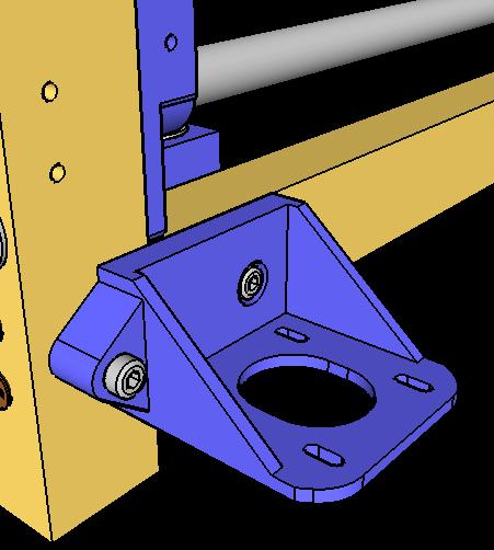


10 Horizontal drive installation - part 1 M4x45 Mount the screw in the countersink hole first M4x40 M4x40 Install the motor support M5 nut 625 bearings Overall view M5 nut - use heat and / or glue to fix it 20 mm Open Source oam utter OS 0.2 Page 10 of 22


 M5 self")


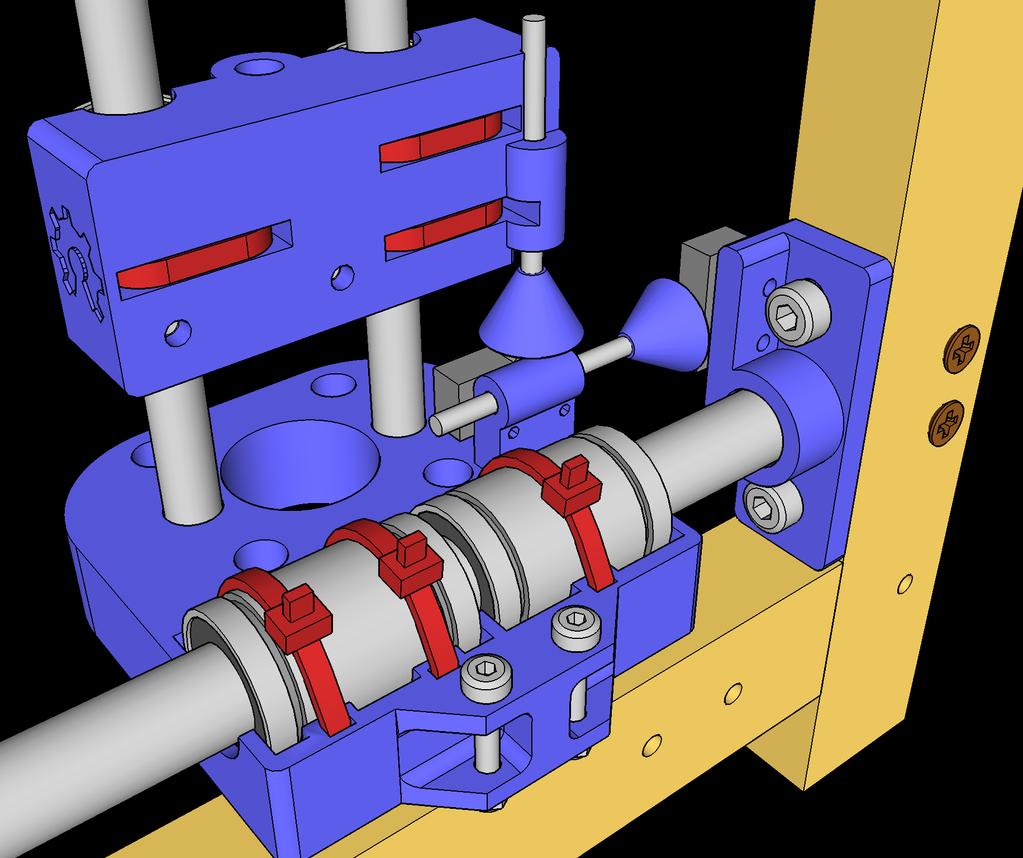
11 Horizontal drive installation - part 2 5 mm small washer Slide in the pulley from the top Tighten very lightly avoid useless stress on the bearings 625 bearings M5 self locking nut tighten so it barely touches the bearing 5 mm wide washer Tighten firmly (do not crack the plastic) M5 self locking nut 3 small washers keep the bearing in place Slide in the upper support group and pulley and bolt it to the frame M4 self locking nut 4 mm washer M4x40 Open Source oam utter OS 0.2 Page 11 of 22


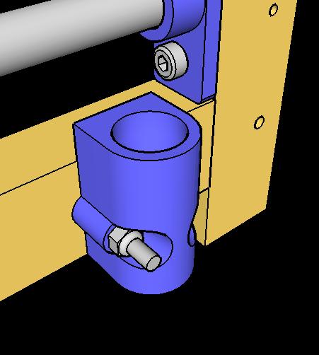
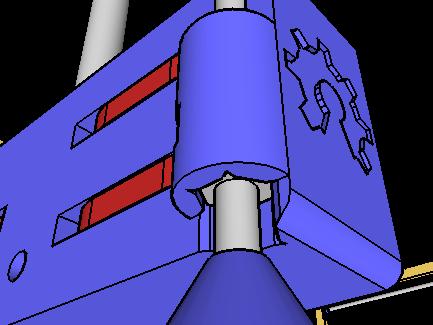
12 Vertical guides installation Install the upper carriage. Install the lower carriage making sure that the end stop support is towards the X end stop. Slide the shaft through the upper carriage, insert the bearings, slide through the lower carriage until they rest on the stepper motor face M3x10 socket head screws Install the motor before sliding in the 8mm shafts Open Source oam utter OS 0.2 Page 12 of 22


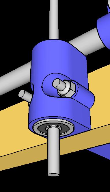
13 Horizontal drive installation - part 3 Pre set position: Tensioner inside guides 5mm Install the screw pins in the upper and lower carriages where the belt will lock to. o not over tighten or the plastic might crack M4x25 M4x20 624ZZ bearing M4 nut M4 blind nut M3x20 Hot glue GT2-18 M3 self locking nut 3mm washer GT2-99 M3x10 GT2-260mm Open Source oam utter OS 0.2 Page 13 of 22


14 Horizontal drive installation - part 4 Insert the belt from the outside, teeths inside Lock the belt on the screws using two zip ties on each side Open Source oam utter OS 0.2 Page 14 of 22

 check that the 8mm guides are vertical")

 ensure that the pulleys are at the right")


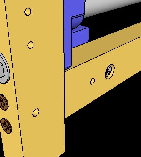
15 Horizontal drive main belts setup Make sure the 18 teeth pulleys are free to move before starting ) check that the 8mm guides are vertical and parallel to the frame. The parts are not on the same plane, using a wood block as reference helps. 2) ensure that the pulleys are at the right height and the belt is straight 1 3) adjust the belt tension: since the machine moves very slow, it doesn't need to be super tight. e careful to not bend the 5mm shaft. 4) double check the measurements and tighten the pulleys set screws Open Source oam utter OS 0.2 Page 15 of 22


16 Vertical carriage preparation 27.5 mm 5 mm 5 mm 12 mm 6 mm evel the edges so the wire will not jam when cutting at high angles 55 mm M3 nut M3x10 M5 nut - use heat to insert Open Source oam utter OS 0.2 Page 16 of 22


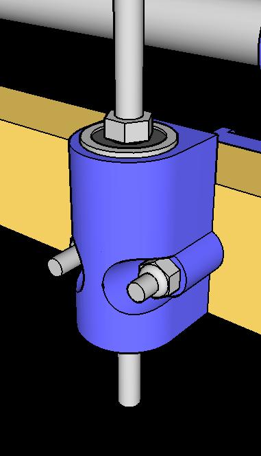
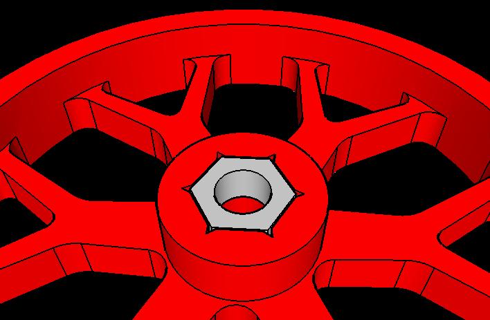
17 Vertical carriage installation M5 Nut Slide the 5*520 threaded rod through the upper carriage, screw through the cursor and fix it to the flexible joint. Insert the flanged bearing on the upper carriage and screw in the retaining nut - it has to be tighten so it just touches the bearing. 625 langed ball bearing M5x520 5x5mm flexible joint Open Source oam utter OS 0.2 Page 17 of XX


18 Main assembly 20x30x1320mm wood beams add diagonal cables to increase frame rigidity 3x40 self tapping screws Open Source oam utter OS 0.2 Page 18 of 22


19 Wire support arc assembly Joiner M5x35 M5 Self locking nut washer on both sides rc guide slider Tension strut Glue at 16 mm Nail M3x35 M3 self locking nut washer on both sides Press fit Tension cable The cutting wire must be electrically isolated from the supporting arc 20x30x1700 wood beam 10x10x730 aluminium beam Note: the wire must be installed when the arc is already on the main machine frame Open Source oam utter OS 0.2 Page 19 of 22


20 nd stop installation xx Microswitch ctuator 3mm threaded rods Open Source oam utter OS 0.2 Page 20 of XX


21 Generate the STL files The STL files are not distributed directly, it's necessary to generate them using OpenS: an open source, multi platform, solid 3 modeller. ownload it from: ownload the file OS-Oscad-0.2 and uncompress to a convenient location. Install the OR- fonts since they are used to generate the logos on the parts. Open the file OS-0.2.scad STL creation workflow: - Select the parts setting the render flags - Preview the result - Render the result - xport the STL file using the file - export - export as STL command. We recommend printing the calibrator part first, check that the tolerances are OK and then go ahead with the other parts. The OpenS file has comments that explain how to tweak the parameters. LM12UU slot Screw and bolts screws should go through free, bolts should fit tightly Zip tie channels LM8UU slot Tempered shafts slots look for a tight fit Render Render flags Preview Open Source oam utter OS 0.2 Page 21 of 22
22 Hardware Store N Hardware Store 3 printed parts Item escription Qty Item escription Qty Item escription Qty 1 3x50 self tapping screw x800mm tempered steel shaft 4 61 Tempered shaft support - L 2* 2 3x40 self tapping screw x550mm tempered steel shaft 4 62 Tempered shaft support - LR 2 3 M5x45 socket head screw LM12UU linear motion bearing 8 63 Tempered shaft support - H 2 4 M5 x 15mm washer LM8UU linear motion bearing 4 64 Tempered shaft support - HR 2 21 M5 x 10 mm washer ZZ flanged ball bearing Reduction gear support 4 5 M5 self locking nut ZZ ball bearing 4 66 GT2-2mm 99 teeth S pulley 2 6 M5 nut x5mm flexible joint 2 67 elt Tensioner 4 7 M4x40 socket head screw 8 38 GT2-2mm 18 teeth aluminium pulley 6 68 Stepper motor support 2 27 M4x45 socket head screw Nema 17 stepper motor 4 69 X arriage - low 2* 8 M4x25 hexagonal head screw 4 40 Micro size switch 4 70 X arriage - high 2 9 M4x20 hexagonal head screw x260mm closed loop GT2 belt 2 71 Y arriage 2* 10 M4 nut 4 42 GT2 belt, 1600mm 4 72 nd stop actuator 4 11 M4 blind nut 4 74 rc Joiner - 20x M4 self locking nut rc tension strut 2 13 M4 washer 6 14 M3x10 socket head screw M3x20 socket head screw 8 16 M3 washer M3 nut 8 18 M3 self locking nut M5x660 Threaded rod 2 20 M5x520 Threaded rod 2 23 M3x35 Socket head screw 2 24 M5x35 Socket head screw 4 25 Soft steel nails 2 26 M3x45 Threaded rod 4 Miscellaneous Item escription Qty 91 20x30x800 wood side frame top x30x800 wood side frame bottom x30x650 wood side frame front x30x650 wood side frame front x30x1320 wood frame connectors 4 96 utting ed 1 97 Wire support blade x30x1700 wood arc main beam x10x730 aluminum arc sides x650mm carbon fiber arc guide 1 76 rc reference plug rc guide slider 1 78 rc guide foot 1 Open Source oam utter OS 0.2 Page 22 of 22
Kossel Rev B Build Guide V1.0
 Kossel Rev B Build Guide V1.0 1 Table of Contents: Step 1: BASE ASSEMBLY Gathering parts: Building the Corners and Base: Step 2: UPPER ASSEMBLY Building Upper: Step 3: VERTICAL RAIL INSTALLATION Building
V4 Premium Kit. Prusa i3 Build Guide
 V4 Premium Kit Prusa i3 Build Guide Hi! Congratulations on your purchase of the DIYElectronics.co.za Prusa I3 kit, the best South African 3D Printer Kit! Hopefully this should serve as complete guide to
SatNOGS. SatNOGS Rotator v3 Mechanical Assembly. This is the assembly guide for the third version of the SatNOGS Rotator.
 SatNOGS SatNOGS Rotator v3 Mechanical Assembly This is the assembly guide for the third version of the SatNOGS Rotator. Written By: Pierros Papadeas 2017 satnogs.dozuki.com Page 1 of 19 INTRODUCTION Notes:
Assembly Guide for Printrbot - Simple Maker s Edition 1405
 Assembly Guide for Printrbot - Simple Maker s Edition 1405 Last update: March 2016 Please Note: be careful on the steps that are underlined 1 Contents Tools Needed:... 3 First step: Check components and
Assembly Instructions Beta Prusa Standard & Deluxe
 Assembly Instructions Beta Prusa Standard & Deluxe 3D Printer Version 2.6 Date Page 1 / 67 General data about the assembly instructions for an incomplete machine according to appendix VI of the EG machinery
Assembly Instructions. Beta Prusa DualX 3D Printer
 Assembly Instructions Beta Prusa DualX 3D Printer Version 2.6 Date Page 1 / 72 General data about the assembly instructions for an incomplete machine according to appendix VI of the EG machinery directive
Assembly Instructions Beta Prusa Standard & Deluxe
 13/11/12 Assembly Instructions Beta Prusa Standard & Deluxe 3D Printer Version 1.0 Date 13/11/12 Page 1 / 66 General data about the assembly instructions for an incomplete machine according to appendix
Part 7 Assembling the X axis
 Part 7 Assembling the X axis 1 2 The X axis is a key part of the printer, it carries the extruder on a carriage that moves the extruder laterally in the X axis. The x axis itself is moved vertically on
Assembly Instructions
 Assembly Instructions Note: Prior to assembly, be sure to remove all printing pads from the printed parts and also be sure to sort through and organize all of your hardware before assembly this will help
ABM International, Inc. Navigator Assembly Manual
 ABM International, Inc. 1 1.0: Parts List Tablet (Qty. 1) Tablet mount (Qty. 1) NOTE: Mount may appear and operate different then image below Control Box (Qty. 1) Motor Power Supply (Qty. 1) 2 X-axis motor
Delta Rostock mini G2& G2s Building instruction
 Delta Rostock mini G2& G2s Building instruction Safety Instructions ShenZhen GETECH CO.,LTD Building the printer will require a certain amount of physical dexterity, common sense and a thorough understanding
Document version: 1.1. Beagle Build manual
 Document version: 1.1 Beagle Build manual TABLE OF CONTENTS Table of contents...2 About the Beagle...3 Change history...4 Safety warnings...4 Required tools...5 1. Bars & Printed parts examination...6
Assembly Instructions
 Assembly Instructions Note: Prior to assembly, be sure to remove all printing pads from the printed parts and also be sure to sort through and organize all of your hardware before assembly this will help
3. X-axis assembly. 3. X-axis assembly. Written By: Jakub Dolezal manual.prusa3d.com/ Page 1 of 13
 3. X-axis assembly Written By: Jakub Dolezal 2018 manual.prusa3d.com/ Page 1 of 13 Step 1 Tools necessary for this chapter Needle-nose pliers for zip tie trimming. 2.5mm Allen key for M3 screws 2mm Allen
Sbach 1,2m 3D/aerobatic EPP model Building instructions
 Sbach 1,2m 3D/aerobatic EPP model Building instructions Please refer to the Diagram sheet Diagrams A, B Press 2 carbon strips (1x3x1000 mm) into the grooves in the sides of the fuselage central part (the
Code Product Qty 1 Top Vertex 3 2 Hot End Housing 1 3 Bottom Vertex 3 4 Print Platform Lock 3 5 End Stop Holder 3 6 Filament Feeder Motor Bracket 1 7
 List of Parts Code Product Qty 1 680mm Extrusion 3 2 Power Supply 1 3 240mm Extrusion 9 4 42mm Nema 17 Stepper Motor 3 5 Slider-Hotend Connecting Rod 6 6 48mm Nema 17 Stepper Motor 1 7 Linear Rail with
Written By: Brook Drumm
 Simple 1401 Assembly For kits produced between 1/15/14-6/1/14. This guide is for kits with the Fan Shroud. Instructions for metal and wood extruder (and bed) included below. Written By: Brook Drumm TOOLS:
Printrbot Simple (Model 1403) Rev F Printrboard
 Rev F Printrboard") Printrbot Simple (Model 1403) Rev F Printrboard Printrbot Simple is currently shipping with the Rev F Printrboard. Check which rev Printrboard your Simple kit includes and use the corresponding instructions.
Printrbot Simple (Model 1403) Rev F Printrboard Printrbot Simple is currently shipping with the Rev F Printrboard. Check which rev Printrboard your Simple kit includes and use the corresponding instructions.
Ender-3 3D Printer. Instructions for assembly
 Ender-3 3D Printer Instructions for assembly This guide is for the Ender-3 3D printer. Select the correct input voltage to match your local mains (220V or 110V). Because of software/hardware upgrades and
Mostly Printed CNC Assembly Instructions
 Index 0 Calculate the length of your conduits, belts, etc.... 2 Conduits... 2 Belts... 2 All-thread... 2 1 Parts you need... 2 Unit-independent... 3 Imperial... 3 Metric... 3 2 Part preparation... 4 4x
(Assembling Guide supplied by imakr ) with the support of MyMiniFactory.com
 with the support of MyMiniFactory.com") (Assembling Guide supplied by imakr ) with the support of MyMiniFactory.com Summary Congratulations on beginning on your journey into 3D printing with the STARTT 3D printer. In this guide, you will have
(Assembling Guide supplied by imakr ) with the support of MyMiniFactory.com Summary Congratulations on beginning on your journey into 3D printing with the STARTT 3D printer. In this guide, you will have
AndyMark DART 12.
 AndyMark DART 12 Part Number Description QTY These Parts Are Pre-Assembled by AndyMark am-0031 Bearing, 3/16"ID (R3) 1 am-0209 Bearing, 3/8"ID 1614ZZ 2 am-1028 Screw, #10-32x3/8 Pan Head Philips 8 am-1121
Assemble Instruction of Geeetech Acrylic Prusa I3. pro C
 Assemble Instruction of Geeetech Acrylic Prusa I3 pro C Safety Instructions Shenzhen GETECH CO.,LTD Building the printer will require a certain amount of physical dexterity, common sense and a thorough
Nancy s Knit Knacks LLC 4 Yard Option Upgrade Kit Assembly Instructions and User Manual
 Nancy s Knit Knacks LLC 4 Yard Option Upgrade Kit Assembly Instructions and User Manual Thank you for purchasing our 4 Yard Option (4YO) Upgrade Kit. To install this upgrade you are simply going to assemble
AM8 Printer A metal frame for your Anet A8 By Pheneeny v1.0 April 20, 2017
 AM8 Printer A metal frame for your Anet A8 By Pheneeny v1.0 April 20, 2017 Please read this entire document before printing parts or building this frame Disclaimer: This guide is for informational purposes
PRS Retro Z-Axis Installation
 PRS Retro Z-Axis Installation Page -1- PRS Retro Z-Axis Installation This document is a guide to installing the PRS Retro Z-axis on early ShopBot models. It describes installation for PR models with PK299
Assemble Instruction of Geeetech Acrylic. Prusa I3 Pro C
 Assemble Instruction of Geeetech Acrylic Prusa I3 Pro C Version 04-11-2016 Safety Instructions Building the printer will require a certain amount of physical dexterity, common sense and a thorough understanding
Assemble Instruction of Geeetech Acrylic Prusa I3. Pro & pro B
 Assemble Instruction of Geeetech Acrylic Prusa I3 Pro & pro B Version 04-11-2016 Safety Instructions Shenzhen GETECH CO.,LTD Building the printer will require a certain amount of physical dexterity, common
Step 1 Assemble Base Frame Parts: 2040 Aluminium profile 250mm 1pcs Base Plate 1pcs M4-8mm screw 3pcs M4 T-Nut 3pcs
 Step 1 Assemble Base Frame 2040 Aluminium profile 250mm 1pcs Base Plate 1pcs M4-8mm screw 3pcs M4 T-Nut 3pcs Put the aluminium profile on the base plate, secure them with 3pcs M4-10mm screws & T-Nut Step
ABM International, Inc.
 ABM International, Inc. Lightning Stitch required 1 1.0: Parts List head and motor assembly (Qty. 1) Reel stand (Qty. 1) Needle bar frame clamp (Qty. 1) Motor drive (Qty. 1) 2 Cable harness with bracket
RC-TEK Ltd. SKYSHARK 450 REFERENCE MANUAL. Copyright 2007 RC-TEK, All Rights Reserved
 RC-TEK Ltd. SKYSHARK 450 REFERENCE MANUAL Frame Assembly On each page of this manual the parts required for each step will be listed below along with a set of images showing the stages of each part of
AX1001. Smith/Functional training Combo-free weight ASSEMBLY INSTRUCTIONS
 AX1001 Smith/Functional training Combo-free weight ASSEMBLY INSTRUCTIONS EXPLODED DIAGRAM 83 84 84 85/86 87 87 88 89 90 91 62 64 64 64 64 64 64 65 65 65 65 66 66 65 66 66 65 63 63 66 67 68 55 66 66 70
The Portable Open Source 3D Printer
 http://web.archive.org/web/201502142011/http://www.tantillus.org/build_3.html Page 1 of 12 captures 12 Oct 12 - Feb 15 The Portable Open Source 3D Printer Home Start Case X/Y Axis Extruder Z Axis Electronics
Deck Mount Installation with Bench
 Deck Mount Installation with Bench 1. Mark track with square. 2. Cut tracks with saw. 3. Drill ¼ hole (if needed.) 4. Countersink track. 5. Countersink all track 6. File all track ends. ends. 7. Lay out
Number Wheeler P/N Description Set Rex P/N Notes Base 1 J Support, Right 1 J Support, Left 1 J Nut (M8)
") 1 603500 Base 1 J001 2 603501 Support, Right 1 J002 3 603502 Support, Left 1 J003 4 600328 Nut (M8) 4 5 600130 Spring Washer (8mm) 4 6 600344 Roll Pin (M6x30) 4 7 600129 Socket Hd Cap Screw (M8x25) 4 8
1 603500 Base 1 J001 2 603501 Support, Right 1 J002 3 603502 Support, Left 1 J003 4 600328 Nut (M8) 4 5 600130 Spring Washer (8mm) 4 6 600344 Roll Pin (M6x30) 4 7 600129 Socket Hd Cap Screw (M8x25) 4 8
Name Standard or Description QTY.
 Part List Part Number Name Standard or Description QTY. 1 Base - 1 2 Nut Hexagon Nut ISO - 4032 - M3 19 3 Motor/Encoder Assembly Mabuchi RS-645VA and Encoder 1 1 4 M3x10 Screw ISO 7045 - M3 x 10 2 5 Steel
Operating Instructions
 Operating Instructions Holding the material against the angle gauge slide it into the forming head. Be sure that the material remains against the gauge until work is finished. NOTE: This machine will handle
Legacy Woodworking Machinery a division of Phantom Engineering. The Legacy CNC. Assembly Manual
 Legacy Woodworking Machinery a division of Phantom Engineering The Legacy CNC Assembly Manual New Orientation of the Legacy Step one: Re-orientation of the machine Remove the X-axis screw and supports.
FORZA 700 SPEED Supplemental manual
 The FORZA 700 has evolved into a Speed Monster. The finely honed form minimizes air resistance, and the forward tilting rotor head helps transform all available power into speed. Fly beyond limits with
MM540 Installation Instructions IMPORTANT SAFETY INSTRUCTIONS - SAVE THESE INSTRUCTIONS
 MM50 Installation Instructions IMPORTANT SAFETY INSTRUCTIONS - SAVE THESE INSTRUCTIONS Please read this entire manual before you begin. Do not unpack any contents until you verify all requirements on PAGE.
Installation Instructions for FC2 & FC15 Forward Controls for the Super Magna
 Installation Instructions for FC2 & FC15 Forward Controls for the Super Magna It is highly recommended that you use a thread lock compound such as Loctite brand on all threads to keep them from vibrating
SPARE PARTS LIST MODEL NO. LB1200F PAGE 1 ITEM PART NO. DESCRIPTION QTY NOTE
 PAGE 1 001 JM21000018 HEX.SOCKET HEAD SCREW M5X12 4 002 JM21000019 SPRING WASHER 5 4 003 JM21000020 FLAT WASHER 5 4 004 JM21000021 UP COVER COMPLETE 1 005 JM21000025 MICRO SWITCH FIX PANEL A 1 006 JM21000026
Electric Skein Winder
 Electric Skein Winder Assembly and Use Package Contents 1 - Triangular Body (w/ motor) 1 - Cross Arm 1 - Left Foot (w/ yarn guide) 1 - Right Foot 1 - Adjustable Finger (w/ yarn clip) 3 - Adjustable Fingers
Installing CNC Stepper Motor Mounts On A Sherline Mill
 Installing CNC Stepper Motor Mounts On A Sherline Mill P/N 6700 (6710 Metric) 5000/5100/5400/5410 Mills P/N 6705 (6715 Metric) 2000/2010 Mills USING THE TEMPLATE BLOCKS TO LOCATE NEW MOUNTING HOLES FOR
Geeetech Delta Rostock mini G2 pro / G2s pro Building Instruction
 Geeetech Delta Rostock mini G2 pro / G2s pro Building Instruction (Document version: 04-11, 2016) CONTENT Safety Instructions... 1 Preparation... 2 1 Base Assembly... 3 1.1 Motor holder assembly... 3 1.2
001-Component-build. Build the following Contraptor components before assembly:
 001-Component-build Build the following Contraptor components before assembly: http://www.contraptor.org/make-linear-rail-v2#assembly http://www.contraptor.org/make-linear-bearings-v2#assembly http://www.contraptor.org/make-sliding-elements#assembly
Removing and Replacing the Y-truck
 Service Documentation Removing and Replacing the Y-truck To remove and replace the Y-truck you will need the following tools: 4mm Allen wrench 12mm stamped flat wrench #2 Phillips screwdriver (magnetic
INSTALLING YOUR NEW SPRING LIFT ARM KIT
 INSTALLING YOUR NEW SPRING LIFT ARM KIT 1. Measure the distance that the roof is to be raised. [If your lift system is completely non-functional, you will need to calculate or estimate this distance as
Piazzola Pergola Awning Manufacturing and installation guide
 Piazzola Pergola Awning Manufacturing and installation guide Date Changes Page General information Maximum and minimum width Width Projection 150 to 349 cm 350 to 500 cm From 200 to 250 cm X From 251 to
Record the serial number and date of purchase in your manual for future reference.
 10 Woodworking Bandsaw Model: 10-305 Parts List Record the serial number and date of purchase in your manual for future reference. Serial number: Date of purchase: Part # 10-305PL1 For more information:
Step 1 Assemble Base Frame
 Step 1 Assemble Base Frame Parts: 2040 Aluminium profile 250mm 1pcs Base Plate 1pcs M4-8mm screw 3pcs M4 T-Nut 3pcs Put the aluminium profile on the base plate, secure them with 3pcs M4-10mm screws & T-Nut
M2 Assembly. M2 Sub-Assemblies mm Belt Sub-Assembly mm Belt Sub-Assembly Spider Sub-Assembly... 4
 M2 Assembly Table of Contents M2 Sub-Assemblies... 3 630mm Belt Sub-Assembly... 3 702mm Belt Sub-Assembly... 3 Spider Sub-Assembly... 4 Idler Bolt Sub-Assembly... 8 Y Motor Sub-Assembly... 9 X Motor Sub-Assembly...
Citabria Pro. Aerobatic Parkflyer. by Joel Dirnberger
 Citabria Pro Aerobatic Parkflyer by Joel Dirnberger Revision C: December 21, 2004 Citabria Pro Building Instructions Length: Wingspan: Wing Area: Flying Weight: Wing Loading: Functions: Specifications:
FC3920K and FC5539K Automatic Foam Cutting CNC Machines
 FC3920K and FC5539K Automatic Foam Cutting CNC Machines Disclaimer You accept all risks and responsibilities for looses, damages costs and other consequences resulting directly or indirectly from using
LANDING GEAR. 1. Fit landing gear into slots on bottom of fuselage.
 LANDING GEAR 1. Fit landing gear into slots on bottom of fuselage. 4. Use channel-lock pliers to press blind nuts into position (note: drilled hole should be slightly smaller than shaft of blind nut for
Z14 MANUAL TÉCNICO TECHNICAL MANUAL
 Z14 MANUAL TÉCNICO TECHNICAL MANUAL Z14 TECHNICAL INSTRUCTIONS CONTENTS: 1.- Opening the machine 2.- Changing the bridge 3.- Checking if cleaning and greasing is needed 4.- Puller runner bolts 5.- Tray
By C.W. Woodson From the pages of Model Craftsman magazine June, 1937
 By C.W. Woodson From the pages of Model Craftsman magazine June, 1937 As shown in Fig. 1, the tool post grinder for which plans are given here can be used to finish up delicate work to more accurate dimensions
Model No: TC10. Parts Information: Tyre Changer - Automatic
 Page 1 of 11 1 TC10.01 BODY 2 TC10.02 COLUMN 3 TC10.03 HORIZONTAL ARM ASS'Y 4 TC10.04 WASHER 5 TC10.05 RUBBER FOOT 6 TC10.06 COVER 7 TC10.07 SCREW M14x42 8 TC10.08 PRESS COVER 9 TC10.09 STOP-UP 10 TC10.10
4. Z-axis assembly. 4. Z-axis assembly. Written By: Josef Prusa manual.prusa3d.com Page 1 of 18
 4. Z-axis assembly Written By: Josef Prusa 2017 manual.prusa3d.com Page 1 of 18 Step 1 Get the necessary tools 13/17mm spanners 3.6mm flathead screwdriver Needle-nose pliers 2.5 and 1.5mm Allen key Step
Budget Robotics Octabot Assembly Instructions
 Budget Robotics Octabot Assembly Instructions The Budget Robotics Octabot kit is a low-cost 7" diameter servo-driven robot base, ready for expansion. Assembly is simple, and takes less than 15 minutes.
Parts & Tools. O'Cello printing and assembly instructions. o-cello.com
 The O'Cello is a 3D-printable cello developed by Conor O'Kane, which is free to download and print for personal use. This document will show you how to print and assemble your own O'Cello. For the latest
Obtained from Omarshauntedtrail.com
 DaveintheGrave's Halloween Props Animated Crawling Skeleton Build a life-size skeleton torso that realistically crawls across the lawn one arm at a time. 1. Motor Base and Linkage Assembly BASE - I used
400A 40113V, 401A 40120V, & 401AL 40120VL ALUMINUM VERTICAL 4000 LB LIFT INCLUDES SCREW LEG ASSEMBLY INSTRUCTIONS
 12/11/07 PAGE 1 OF 12 400A 40113V, 401A 40120V, & 401AL 40120VL ALUMINUM VERTICAL 4000 LB LIFT INCLUDES SCREW LEG ASSEMBLY INSTRUCTIONS Thank you for purchasing our product! *Please read these instructions
Manufacturing and installation instruction. Solidare Verso. Pergola awning (bottom mounted)
") Manufacturing and installation instruction Solidare Verso Pergola awning (bottom mounted) Solidare Verso pergola awning 11-05-2017 * * A T T E N T I O N * * AVZ accepts no liability for any errors in this
Manufacturing and installation instruction Solidare Verso Pergola awning (bottom mounted) Solidare Verso pergola awning 11-05-2017 * * A T T E N T I O N * * AVZ accepts no liability for any errors in this
MM340 Installation Instructions IMPORTANT SAFETY INSTRUCTIONS - SAVE THESE INSTRUCTIONS
 MM30 Installation Instructions IMPORTANT SAFETY INSTRUCTIONS - SAVE THESE INSTRUCTIONS Please read this entire manual before you begin. Do not unpack any contents until you verify all requirements on PAGE.
Removing the Z-Axis lead screw
 Page 1 of 8 TITLE: Sabre Z-Axis Lead Screw Replacement Procedure Gerber FastFact #: 5048 Supplied by: Gerber Hardware Support Last Modified: June 14, 2007 Summary: Tools used: The following procedure explains
Welcome! Table of Contents
 Welcome! The folks at Random Idea Generator Shop would like to thank you for purchasing our 3D printer kit. We are dedicated to providing an easy to build kit with customizable options to meet your requirements.
High performance 90mm fiberglass jet
 High performance 90mm fiberglass jet Assembly manual For intermediate and advanced fliers only! Specs Wingspan: 1255mm Fuselage length: 1250mm Flying weight: 2600-3000g Wing area: 22.6 dm² Wing loading:
LCD LIFT Flat Panel Display System Installation Manual. Table of Contents
 LCD LIFT Flat Panel Display System Installation Manual Table of Contents Page Installation Overview... 2 Trim Ring Installation... 3 LCD Lift Installation....4 Actuator Switch Installation.5 Top Plate
INSTALLATION LS MODEL
 INSTALLATION LS MODEL Page 2 TABLE OF CONTENTS Section 1: Included parts... pg 4 Section 2: Installing the Shirley Stitcher II on Quilt Frame.. pg 5 Section 3: Connecting Shirley Stitcher II to Tin Lizzie
Shapeoko XXL Assembly Guide
 Shapeoko XXL Assembly Guide 04/27/2016 XXL Packing LIst Item Qty Description Y-Carriage (left) 1 Y-Carriage (right) 1 X/Z Assembly 1 40 Rail 3 1 rail has mounting holes for controller Wasteboard Half 2
25-200H. 12 Planer / Jointer. with Helical Cutterhead. Parts List.
 25-200H 12 Planer / Jointer with Helical Cutterhead 4001824 Parts List www.rikontools.com CABINET ASSEMBLY PARTS EXPLOSION & PARTS LIST KEY NO. DESCRIPTION KEY NO. DESCRIPTION 1 Pan Head Screw M6x12 P25-200H-1
LYMANBOT 3D PRINTER V3 Construction Manual
 LYMANBOT 3D PRINTER V3 Construction Manual Page 1 Read this whole Manual before starting to construct this Printer. User excepts all liability for the use of this Manual and the construction of this Printer.
aluminium profile system
 aluminium profile system 63 AME System aluminium profiles overview series profiles introduction 80x80 x80 x80/180 x Aluminium profiles are provided with longitudinal grooves which can be used in conjunction
Star Trac Turbo Trainer Assembly & Setup
 Star Trac Turbo Trainer Use the following procedures to unpack and assemble your Turbo Trainer manufactured by Star Trac. UNPACKING AND PARTS LIST Position the shipping carton so the Heavy End logo is
STANDARD CANOPY WORK REPORT B-1
 STANDARD CANOPY WORK REPORT B-1 No. Check Parts / Tools Qty _ Canopy Lock 1 [ ] 6E2-3 Canopy Hinge Block 1 2 [ ] 6E4-5 Canopy Side Frame 2 2 [ ] 6E2-1 Canopy Lock Assembly 1L + 1R 3 [ ] 6E2-4 Rear Lock
Assembly Instructions
 P/N 8650/8655 Assembly Instructions NOTE: Your Sherline CNC Cam Grinder is double boxed and secured to a wooden shipping frame. Upon delivery, check the outer box for damage. If the box is damaged, take
WorkBee CNC. Mechanical Assembly Instructions - Screw Driven
 WorkBee CNC Mechanical Assembly Instructions - Screw Driven Table of Contents 1.0 Getting Started 2 1.1 About The Kit 3 1.2 Check Product Contents 3 1.3 Tools Required 3 1.4 Notes on Assembly 3 2.0 Assembly
SERIES I MILLING MACHINES
 INSTALLATION, OPERATION, MAINTENANCE, AND PARTS LIST SERIES I MILLING MACHINES TP5260 Revised: August 29, 2005 Manual No. M-450 Litho in U.S.A. Part No. M -0009500-0450 June, 2003 MAINTENANCE PROCEDURES
G0513X2 Main -87- G0513 Series Bandsaws 82V V2 82-6V2 95A V2 82-5V2 82-1V2 82-4V V A
 G0513X2 Main 23 55 22 48 17 17-1 17-2 21 7 17-3 17-2 17-4 24 17-5 18-5 22 24 21 55A 50 8 9 49 11 12 13 14 15 47 16 10 46 45 3 44 43 39 38 37 39 40 32 33 36 42 34 35 2 25 28 18-4 18-2 18-3 31 30 29 18-1
(Build Instructions)
") (Build Instructions) Specifications * Wingspan: 58cm * Length: 50cm * Flying Weight: 59 grams * Channels: 3 (Rudder Elevator Throttle) * Suggested Receiver: 4Ch Micro * Motor: 8mm GearDrive * Prop: GWS
(Build Instructions) Specifications * Wingspan: 58cm * Length: 50cm * Flying Weight: 59 grams * Channels: 3 (Rudder Elevator Throttle) * Suggested Receiver: 4Ch Micro * Motor: 8mm GearDrive * Prop: GWS
12. Wings, Flaps, Ailerons and Struts
 12. Wings, Flaps, Ailerons and Struts Fit Aileron Hinges Reference: Drawing 20270K2 Photo 12.1 Parts Required: 2007092 Aileron LS 200809N Aileron RS 2001394 Hinge 3/16 A1 (4) 2001694 Hinge Pin (4) PH0059N
Bed Extension Kit 16 Instructions
 The premier source of tooling, parts, and accessories for bench top machinists. Bed Extension Kit 16 Instructions This kit converts a 7 10, 7 12, and 7 14 mini lathe manufactured by SIEG (including those
SECTION 7. SAFETYING
 9/8/98 AC 43.13-1B SECTION 7. SAFETYING 7-122. GENERAL. The word safetying is a term universally used in the aircraft industry. Briefly, safetying is defined as: Securing by various means any nut, bolt,
Depending on the size you ordered you will have either 5 Foot sections which will build the 10 Foot frame or 6 Foot sections which will build the 12
 XL Quilting Frame 1 Depending on the size you ordered you will have either 5 Foot sections which will build the 10 Foot frame or 6 Foot sections which will build the 12 Foot frame Printed 2 June 2014 Updated
Installation and Assembly - Universal Articulating Swivel Double-Arm for 42" - 60" Plasma Screens
 Installation and Assembly - Universal Articulating Swivel Double-Arm for 42" - 60" Plasma Screens Models: PLAV 70-UNL, PLAV 70-UNL-S PLAV 70-UNLP, PLAV 70-UNLP-S R This product is UL Listed. It must be
Assembly instructions
 Nerdy Gurdy Assembly instructions This manual describes how to assemble a Nerdy Gurdy. Go to http://www.nerdygurdy.nl for more info about these instruments. Jaap Brand The Netherlands January 2018 General
SECTION 9: PARTS. Table Breakdown REF PART # DESCRIPTION REF PART # DESCRIPTION
 SECTION 9: PARTS Table Breakdown 1 2 3 4 5 6 7 8 9 10 11 12 13 14 15 16 17 18 19 20 21 22 23 24 23 25 17 26 27 8 1 P0675001 CAP SCREW M8-1.25 X 30 15 P0675015 SUPPORT BLOCK 2 P0675002 TABLE SUPPORT BLOCK
Super Sky Surfer 2000 Assembly Instructions
 Super Sky Surfer 2000 Assembly Instructions Note: Plug and Play version of the Sky Surfer comes with fuselage pre-glued and motor/servos installed. If you wish to route antennas or wires through the tail,
TITAN2-EDGE Public Access Computer Station Dual Track
 TITAN2-EDGE Public Access Computer Station Dual Track TITAN2-EDGE Rev A 6/17 Model TITAN2-EDGE ASSEMBLY AND ADJUSTMENT TITAN2-EDGE PARTS AND TOOLS PLEASE REVIEW these instructions before beginning the
Model PLM5113N PETROL LAWN MOWER
 Strana 1 / 2 Strana 2 / 2 Strana 1 / 4 001 671006065 "BLADE TIGHTEN BOLT 3/8""24" 1 002 671010730 LID SHAPE WASHER 1 003 DA00000973 BLADE 510MM 1 004 671015252 BLADE SUPPORT 1 005 DA00000535 FLAT KEY 1
re3d Assembling Gigabot: "Flatpack"
 re3d Assembling Gigabot: "Flatpack" Your Gigabot was assembled, calibrated, tested, and taken apart for shipping purposes. All you need to do is reassemble it, and you're ready to go! Written By: Chris
Geeetech Acrylic I3 Pro C 3D Printer
 Geeetech Acrylic I3 Pro C 3D Printer Copyright Declaration The copyright of this manual belongs to the Shenzhen GETECH CO., LTD. (hereinafter referred to as the "Geeetech"), and all rights reserved. No
Operating Instructions For Lockformer Button Punch Flanger
 Capacity: 20 to 28 Gauge Galvanize Operating Instructions For Lockformer Button Punch Flanger To satisfactorily form the 90º button punch flange on light gauge materials, it was necessary to form the metal
Easy Step by Step Manual
 Easy Step by Step Manual Teletower Mini XL Wall-Floor installation The tower packages #1-#2-#3 Open Base Package #1 for the main tower parts. Here you see the three tower tubes (H-Head, M-Middle, F-Feed)
MM750 Installation Instructions
 MM750 Installation Instructions IMPORTANT SAFETY INSTRUCTIONS - SAVE THESE INSTRUCTIONS Please read this entire manual before you begin. Do not unpack any contents until you verify all requirements on
3D PRINTER. Pack 11. Anything you can imagine, you can make! 3D technology is now available for you at home! BUILD YOUR OWN
 BUILD YOUR OWN Pack 11 Anything you can imagine, you can make! 3D PRINTER Compatible with Windows 7 & 8 Mac OS X 3D technology is now available for you at home! BUILD YOUR OWN 3D PRINTER CONTENTS PACK
Screws. Introduction. 1. Nuts, bolts and screws used to clamp things together. Screws are used for two purposes:
 Screws Introduction Screws are used for two purposes: 1. To clamp things together. 2. To control motion. 1. Nuts, bolts and screws used to clamp things together. Nuts, bolts and screws that are used for
TITAN-BIT KEY-CUTTING MACHINE INSTRUCTION MANUAL
 TITAN-BIT KEY-CUTTING MACHINE INSTRUCTION MANUAL Contents: 1 PRESENTATION AND GENERAL ASPECTS... 3 1.1 GENERAL POINTS... 3 1.2 TRANSPORT AND PACKING... 3 1.3 IDENTIFICATION LABEL... 3 2 CHARACTERISTICS
Giraud Tool Company, Inc.
 Motor Upgrade for Gracey Trimmer This package is intended to allow the user to upgrade their Gracey trimmer with a higher rpm motor and convenience features not found in the production offering. This upgrade