Assembly instructions
|
|
|
- Joseph Stone
- 5 years ago
- Views:
Transcription
. Don t glue the bridge or any part that s adjustable.")
1 Nerdy Gurdy Assembly instructions This manual describes how to assemble a Nerdy Gurdy. Go to for more info about these instruments. Jaap Brand The Netherlands January 2018 General directions: The parts are glued together with regular wood glue (not included in the kit). Don t glue the bridge or any part that s adjustable. Make sure that all surfaces that touch are fully glued together. This prevents undesirable vibration when you re playing. When removing parts from the plate that are still attached, it s best to cut the attached points with a sharp knife, to avoid splintering. Before gluing, it is wise to assemble the parts without glue, so that you re sure how they fit together. You can assemble most of the instrument without glue, to get an idea of how the parts go together. It s best to read through the whole sequence, before starting. If you do something wrong, it is possible to release wood glue by heating it (e.g. with a pressing iron)

2 Parts needed wood sheet 3mm 4x sheet 6 mm 2x Loose parts Tuning pegs 5x threaded rod M8 6,5 cm 1x threaded rod M8 22 cm 1x nut 8mm 11x nut M3 4x bolt M2,5 x 10 48x bolt M3 x 10 4x bearing 8x22 3x screw 2,5 x 13 4x screws 3.5 x 17 6x spacer ring 8,4 mm 5x some felt 1x ground ring terminal 2x strings Viola D (melody string) 2x viola G / tennis racket string (trumpet string) 1x Cello C (bourdon) 1x printed parts knob (A) 1x tangent high (B) 28x tangent low (C) 20x shaft nut (D) 1x bearing ring (E) 2x strap pin (F) 2x front bearing support (G) 1x front bearing washer (G) 1x backplate glueing jig (H) 1x Semi-finished parts wheel 1x Note: you will need to tap thread into some parts, after printing
: Standard wood glue (retractable) knife")

3 Standard electric guitar tuning pegs (5x) You will need the following materials to build your Nerdy Gurdy): Standard wood glue (retractable) knife A number of gluing clamps Varnish (optional, but recommended) Sand paper Some tools (screw drivers, 13 mm spanner, etc.) Some basic woodworking skill and patience :)
 The two")
 You can use some books to press")
4 1) Glue the borders to the top and bottom of the Nerdy Gurdy Notes: Make sure that you glue the border to the correct side of the top plate: it s not symmetric (red circle) The two borders are symmetric and identical Make sure that the parts are nicely centered. You can use mating parts to check alignment (picture below) You can use some books to press the parts together


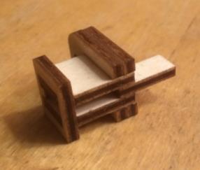
5 2) Assemble the head and front bearing support head Front bearing support


6 3) Mount the head, pillar and rear between the top plate and bottom plate. Notes: Make sure that the opening at the rear side is at the top of the Gurdy (red circle).


.")
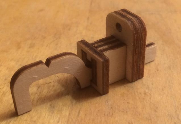
7 Front bearing The shaft is screwed into a bush at the front bearing, to avoid it from rattling. It s most easy to assemble this before you attach the sides to the instrument. There is a hole in the bush to prevent it from rotating, when you re assembling the shaft (red circle). Attach the bearing holder with 2 x [screw, 2.5 x 13]


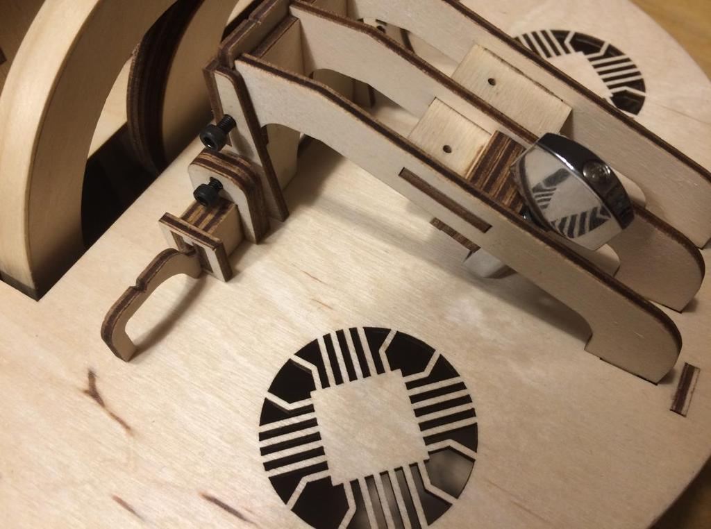
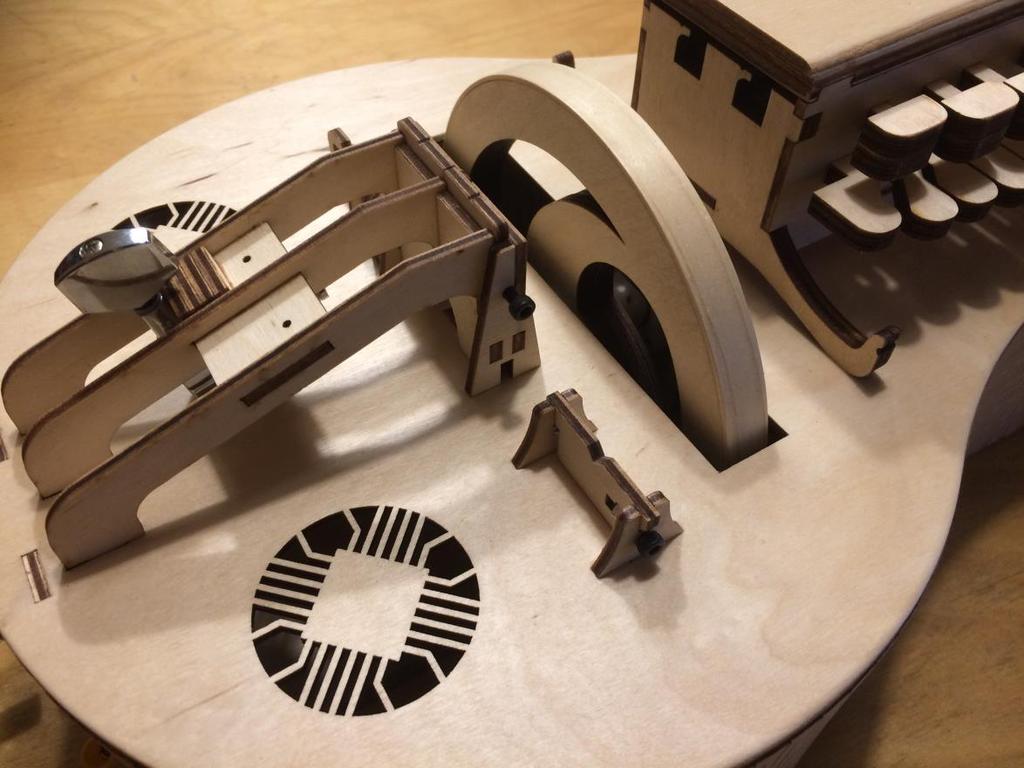
8 3) Mount the sides, starting from the head Notes: You can glue the parts in steps, if you don t have enough clamps (like me). I use the machine heads to clamp the head plates together. Complete the head, assemble the bridge Notes: You don t need to glue the bridge: it may be nice to be able to replace it. A spare part is included. Some spacers are included (red circles)


9 Assemble the tailpiece Make sure these parts are on the correct side, as shown Notes: Make sure that you insert the nuts, before you glue everything together. I use the top plate as a mold, to ensure the spacing of the bridge parts is correct.


10 Place the bolts, wedge parts and bridge segments There are two types of tuning peg. For the other positions both will fit ok. For the tail piece you need to use the correct version.


11 Glue the rear cover pieces together A tool is included to align the pieces for gluing Assemble the key box


12 Glue the lid pieces together Notes: The lid consists of 3 layers. You can decide whether you put the flat plate, or the plate with letters on top.


13 Glue the buzzing bridge support together


14 Assemble the supports for the drone bridge Apply lacquer You may want to lacquer or paint your parts at this point in the assembly. Glue an extra layer on top of the short keys Notes: The numbers are on the top of the keys. That s the side on which you need to stick the extra layer.


15 Glue the key box to the body, and assemble keys and tangents Assemble the bourdon support and buzzing bridge support Don t glue these parts, just place them!
16

![5 x 13]).](/docs-images/94/118228688/images/17-1.jpg "The knob is fixed with a locking nut (red circle).")
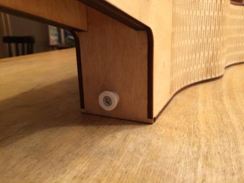
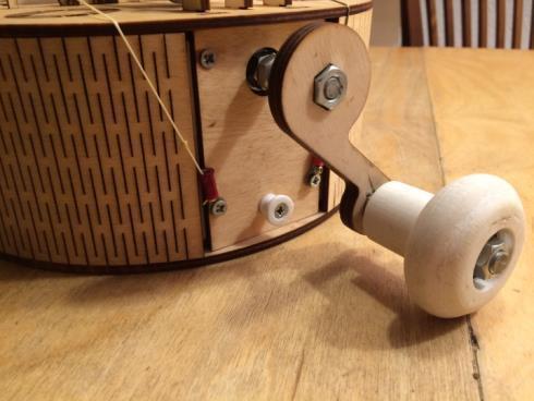
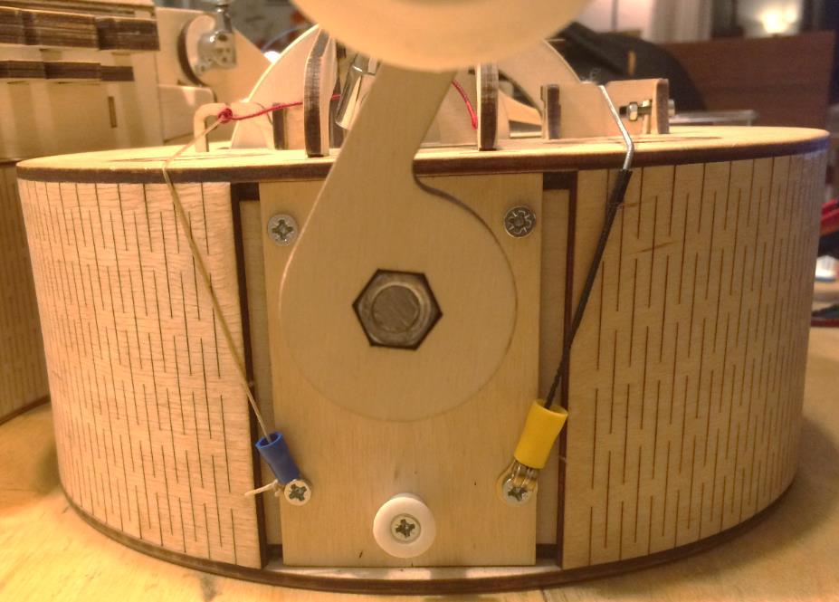
17 Assemble the shaft The printed ring is screwed to the back plate, to secure the bearing (2 x [screw, 2.5 x 13]). The knob is fixed with a locking nut (red circle). Alternatively, you can glue a regular nut into place.

18 163 mm 134 mm


19 Glue the wheel together and glue a strip around the wheel First you need to glue the two layers of wheel together. Next you need to glue a strip of veneer around the edge. This is the hardest part of building the Nerdy Gurdy, and it s important that you do this well. The roundness and smoothness of the wheel will determine the quality of the sound to a large measure. The best way to achieve a smooth wheel is to glue a strip of wood around your wheel. The thickness should be about 1 mm. This can be a bit hard to come by: if all else fails you can reduce a strip of 4 mm plywood with a router (that s what I did for my first few wheels) Here s what you do: Obtain a piece of 1 mm thick veneer, and cut a strip along the grain direction. The strip should be a few mm wider than your wheel. Soak the strip in hot water, and gradually bend it. I usually put the strip inside a pan, and then transfer it to a smaller pan when the tension starts to lessen. Cut a slanted edge to one side, wrap it around the wheel, and draw where to cut on the other side.


20 Apply wood glue to the wheel, and wrap the strip around the wheel. Firmly pull it tight with cable ties.

21 The best way to make sure that the wheel is straight on the shaft is to use a slow drying glue, and align the wheel inside the hurdy Gurdy. Spin the shaft a few times, and correct the alignment. Then allow the glue to dry.


22 Assemble the wheel The wheel slides into the slot on top, and you screw the shaft into the wheel. In the end, the shaft needs to be screwed into the bush with the front bearing. Insert a pin into the bush, to prevent it from rotating: You may need to tweak the locations of the nuts on the shaft a bit, to get the shaft properly aligned and straight. The shaft may not be perfectly straight, so you will need to true the wheel after you assemble it. Rotate it by hand and apply a scraping iron or horizontal chisel, until it is perfectly round. Afterwards, finish with fine sanding paper.

23 Mount the strap pins

24 Mount the strings

25 Notes: You need to tie a short string from the machine head at the rear, to the string. With this knob you can adjust the trumpet effect. You may need to tweak the location of the string a bit, to get a good buzzing effect.
26 Final notes I ve designed this instrument with the purpose of making a Hurdy Gurdy with an acceptable sound, for a very good price. I hope that it enables people to start playing the instrument who would not have had the means otherwise, or are hesitant to invest thousands of dollars straight away. The design is unconventional: it was designed from scratch with the above purpose in mind. Therefore the construction method is in many ways different from traditional instruments. It does however sound pretty good, and it is very playable. And because of the material and the method of construction, it is very stable New players will still need to learn how to properly apply rosin to the wheel, and cotton to the strings. But there are many tutorials online, if you don t have experienced players who can teach you. Enschede, January 2018 Ps. This manual and the Nerdy Gurdy itself are an ongoing project. Please let me know how they can be further improved.
Assembly instructions
 Nerdy Gurdy Assembly instructions This manual describes how to assemble a Nerdy Gurdy kit. Go to http://www.nerdygurdy.nl for more info about these instruments. Jaap Brand The Netherlands January 2018
Parts & Tools. O'Cello printing and assembly instructions. o-cello.com
 The O'Cello is a 3D-printable cello developed by Conor O'Kane, which is free to download and print for personal use. This document will show you how to print and assemble your own O'Cello. For the latest
Installation Instructions for FC2 & FC15 Forward Controls for the Super Magna
 Installation Instructions for FC2 & FC15 Forward Controls for the Super Magna It is highly recommended that you use a thread lock compound such as Loctite brand on all threads to keep them from vibrating
15 Dovetail Jig. Instruction Manual. Part # 3452
 15 Dovetail Jig Instruction Manual Part # 3452 CAUTION: Please read, understand, and follow all manufacturers instructions, guidelines and owners manuals that come with your power tools. Peachtree Woodworking
Extendable Large Dovetail Jig
 Extendable Large Dovetail Jig Instruction Manual Part # 3458 CAUTION: Please read, understand, and follow all manufacturers instructions, guidelines and owners manuals that come with your power tools.
U-bass Kit Assembly Instructions
 U-bass Kit Assembly Instructions Compiled by playubass.com This guide is built from the instructions found here: http://kalabrand.com/ubass-kit/index.html Tools Needed 5/8 (16 mm) Wrench 7/16 (~11 mm)
Learn to weave on the. Inklette Loom
 Learn to weave on the Inklette Loom THE ASHFORD INKLETTE LOOM top rear peg Inkle bands are strong and useful braids. Create colourful belts, bracelets, ties, guitar straps, shoe laces or trims for weaving.
Owner s Manual e-guitar Kit sg-style Harley Benton E-Guitar Kit SG-Style
 Owner s Manual E-Guitar Kit SG-Style Contents Introduction... 3 Body finish... 4 Neck finish... 4 Assembling of tuners... 5 Neck... 6 Wiring... 7 Bridge assembly... 10 Strap buttons... 11 Setting up...
ABM International, Inc.
 ABM International, Inc. Lightning Stitch required 1 1.0: Parts List head and motor assembly (Qty. 1) Reel stand (Qty. 1) Needle bar frame clamp (Qty. 1) Motor drive (Qty. 1) 2 Cable harness with bracket
Owner s Manual. Bass-Guitar Kit J-Style
 Owner s Manual Bass-Guitar Kit J-Style Contents Introduction... 3 Body finish... 4 Neck finish... 4 Assembling of tuners... 5 Neck... 6 Wiring... 6 Bridge assembly... 8 Strap buttons... 8 Setting up...
Making Simple Bookbinding Equipment
 Tony Firman 20 1 2 19 Notes Tony Firman Tony Firman Bookbinding 18 3 : 2012 Tony Firman Bookbinding P.O. Box 507 Haslet, TX 76052 www.tonyfirmanbookbinding.com 4. When all the tapes have been pinned in
Tool 3-1 A2 Bushing 6 Check if the bushing supports (angle iron) are properly welded with the upper part of the structure pipes. welded bushing suppor
 are properly welded with the upper part of the structure pipes. welded bushing suppor") Rope Pump MANUFACTURING checklist for quality control A Welding General 1 Check if welding jigs are used for welding of the main parts (wheel, structure frame and bushings) 2 Check if the pump parts are
Rope Pump MANUFACTURING checklist for quality control A Welding General 1 Check if welding jigs are used for welding of the main parts (wheel, structure frame and bushings) 2 Check if the pump parts are
Depending on the size you ordered you will have either 5 Foot sections which will build the 10 Foot frame or 6 Foot sections which will build the 12
 XL Quilting Frame 1 Depending on the size you ordered you will have either 5 Foot sections which will build the 10 Foot frame or 6 Foot sections which will build the 12 Foot frame Printed 2 June 2014 Updated
THE PODIUM MUSIC STAND
 THE PODIUM MUSIC STAND 1 Set Assembly Instructions Wooden Parts: a. 1 Column b. 2 Long Slide Pieces c. 2 Slide Spacers (1 long & 1 short) d. 4 Feet e. 2 Fork Pieces f. 1 Fork Spacer g. 2 Long Desk Frame
Silverware Chest Plan
 Silverware Chest Plan 05L14.01 Introduction 1. Measure the space required for your cutlery before beginning this project to be sure that it will fit in the drawers and top compartment. The best way to
Electric Guitar Kit DC Style electric guitar kit
 Electric Guitar Kit DC Style electric guitar kit user manual Musikhaus Thomann Thomann GmbH Hans-Thomann-Straße 1 96138 Burgebrach Germany Telephone: +49 (0) 9546 9223-0 E-mail: info@thomann.de Internet:
TOYOTA MOTOR EUROPE CA Products Division Tel : Fax :
 TOYOTA MOTOR EUROPE CA Products Division Tel : + 32 2 745 26 77 Fax : + 33 2 745 26 99 Ordering part numbers Comments Part Numbers Wooden floor one hatch PZ449-D3C42-11 one hatch with carpet PZ449-D3C42-01
12. Wings, Flaps, Ailerons and Struts
 12. Wings, Flaps, Ailerons and Struts Fit Aileron Hinges Reference: Drawing 20270K2 Photo 12.1 Parts Required: 2007092 Aileron LS 200809N Aileron RS 2001394 Hinge 3/16 A1 (4) 2001694 Hinge Pin (4) PH0059N
Adjustable Hammered Dulcimer Stand
 Adjustable Hammered Dulcimer Stand Musicmaker s Kits (Hwy 36 behind Joseph s Restaurant) P.O. Box 2117 Stillwater MN 55082 651 439 9120 www.harpkit.com PARTS LIST: 1 Set of Assembly Instructions A. 2 front
Woodline USA Woodline Spacer Fence System
 Woodline USA Woodline Spacer Fence System MADE IN THE USA Includes: (1) ¼ Spacer Fence (1) 3/8 Spacer Fence (1) ½ Spacer Fence (1) Hardware Package (1) 3 Piece Brass bar set (2) Setup Blocks Visit Us Online
WOLF PUP LOOM TM & WOLF PUP LT LOOM TM
 WOLF PUP LOOM TM & WOLF PUP LT LOOM TM Assembly Instructions FL3000 FL3006 FL3009 WOLF PUP WOLF PUP LT Find out more at schachtspindle.com Schacht Spindle Company 6101 Ben Place Boulder, CO 80301 p. 303.442.3212
Copyright 2007 MLCS 1
 Copyright 2007 MLCS 1 REFERENCE GUIDE and SPECIFICATIONS: Edge Guides: This 12 Dovetail Template comes complete with 2 Edge Guide Sets one set for Half Blind and one set for Rabbeted Half Blind Dovetails.
Kossel Rev B Build Guide V1.0
 Kossel Rev B Build Guide V1.0 1 Table of Contents: Step 1: BASE ASSEMBLY Gathering parts: Building the Corners and Base: Step 2: UPPER ASSEMBLY Building Upper: Step 3: VERTICAL RAIL INSTALLATION Building
The Portable Open Source 3D Printer
 http://web.archive.org/web/201502142011/http://www.tantillus.org/build_3.html Page 1 of 12 captures 12 Oct 12 - Feb 15 The Portable Open Source 3D Printer Home Start Case X/Y Axis Extruder Z Axis Electronics
Solo AD Style DIY Acoustic Guitar Kit
 Solo AD Style DIY Acoustic Guitar Kit Assembly Manual ADK-1 V 2.0 Copyright 2017 Solo Music Gear. All rights reserved Show Off Your Custom Built Guitar! When you have your guitar finished, please take
ASSEMBLY INSTRUCTIONS
 WWW.NUKE.ROCKS ASSEMBLY INSTRUCTIONS 1 Let s begin our satisfying journey to 3D Printed music by downloading a copy of Nuke s 3D model from www.nuke.rocks. You will obtain a ZIP file which you must decompress,
Precision Steel Car s 100 T Steel Coil Car
 Precision Steel Car s 100 T Steel Coil Car Precision Steel Car www.precisionsteelcar.com info@precisionsteelcar.com Paul Vernon: (513) 571-5739 Revised 4/30/2009 Contents of Kit Main Tube Side Frame 2
LANDING GEAR. 1. Fit landing gear into slots on bottom of fuselage.
 LANDING GEAR 1. Fit landing gear into slots on bottom of fuselage. 4. Use channel-lock pliers to press blind nuts into position (note: drilled hole should be slightly smaller than shaft of blind nut for
Hinge Mortising Jig. One of the make it or break it parts of building a. 6 ShopNotes No. 74
 Hinge Mortising Jig A Mortise for a Hinge. Quick, clean, and accurate that s the only way to describe the mortise you get with a trim router and this hinge mortising jig. One of the make it or break it
CAL-K1 Self-build guitar kit UK Version 1.0
 CAL-K1 Self-build guitar kit 174.460UK Version 1.0 Thank you for buying the CAL-K1 kit. All the wood, hardware and electrical components of a Chord CAL93 guitar are contained in this package. Please read
Post-Paint>Fuselage>Interior>Controls>Fit rudder pedals
 Post-Paint>Fuselage>Interior>Controls>Fit rudder pedals Objectives of this task: To fit the rudder pedals and steering links to the aircraft, and fit the rudder cable to the rudder pedals and set the deflection
The Phoenix. Professional Quilting Frame. Copyright January 1, 2016 Jim M. Bagley, GraceWood, Inc (Reproduction Prohibited) Version 2.
 Version 2.") The Phoenix Professional Quilting Frame Copyright January 1, 2016 Jim M. Bagley, GraceWood, Inc (Reproduction Prohibited) Version 2.1 1 The Phoenix Professional Quilting Frame Parts List Box 1...3 Box
The Phoenix Professional Quilting Frame Copyright January 1, 2016 Jim M. Bagley, GraceWood, Inc (Reproduction Prohibited) Version 2.1 1 The Phoenix Professional Quilting Frame Parts List Box 1...3 Box
CHAPTER 11 3/4" Box (Finger) Joints
 Joints") 53 RTJ400 OPERTION CHPTER 11 3/4" ox (Finger) Joints IMPORTNT SFETY NOTE efore using your Leigh RTJ400 you must have completed the preparatory steps listed in the previous pages, including reading the
53 RTJ400 OPERTION CHPTER 11 3/4" ox (Finger) Joints IMPORTNT SFETY NOTE efore using your Leigh RTJ400 you must have completed the preparatory steps listed in the previous pages, including reading the
ABM International, Inc. Navigator Assembly Manual
 ABM International, Inc. 1 1.0: Parts List Tablet (Qty. 1) Tablet mount (Qty. 1) NOTE: Mount may appear and operate different then image below Control Box (Qty. 1) Motor Power Supply (Qty. 1) 2 X-axis motor
Fortress Fe Posts must always be secured to the deck framing. Fortress Fe Posts should never be attached to only the deck boards.
 Installation Instructions for Fortress Horizontal Cable Panel System with UB-05 Brackets and Fe Posts It is the responsibility of the installer to meet all code and safety requirements, and to obtain all
PILOT SEAT AND HARNESS
 1. Locate the following parts PILOT SEAT AND HARNESS #84 threading needle, 1 each #88 lacing cord, 1 each #119 aluminum seat, 1 each #120 plywood, pilot seat bottom, 1 each #121 wood screw, 3 each #293
HQ Pole Upgrade Kit for HQ Adjustable Table and HQ QuilTable Assembly Instructions 1
 HQ Pole Upgrade Kit for HQ Adjustable Table and HQ QuilTable Assembly Instructions QF09775 The pole upgrade kit can be used with or without the QF09700 HQ Precison-Glide track upgrade kit. What s Included
Astro-Physics Inc. 400QMD Lubrication/Maintenance Guide
 Astro-Physics Inc. 400QMD Lubrication/Maintenance Guide The following guidelines should be followed to lubricate the three main parts of the 400QMD mount. The QMD stands for Quartz Micro-Drive controller.
Tools: Sharpie, Square, Vise, Hack saw, Ruler, Punch, Hammer, File. 2. Cut the stock Place stock in vise and cut with hack saw
 Purpose: MAKE CATAPULT ARM Step 1 Tools: Sharpie, Square, Vise, Hack saw, Ruler, Punch, Hammer, File Materials: Flat aluminum ½ inch stock (see picture below) Gloves required 1. Pick up the aluminum ½
Model 209 Fireback Replacement
 Model 209 Fireback Replacement Please read all the instructions before you begin the procedure. Confirm that you have all the necessary tools and materials. If you have any questions, technical support
Classic Mitered Jewelry Box
 America s leading woodworking authority Premium Plan In this plan you ll find: Step-by-step construction instruction. A complete bill of materials. Construction drawings and related photos. Tips to help
Fig. 2 DORMA-Glas Stand/Issue 02/03 Seite/Page 1/7
 FSW Installation instructions Track rail 75 x 72 mm 1. Ceiling substructure and installation of the track rail (Fig. 1): The track rail must be bolted over its entire length (including the stacking track
Christmas Bell Ornament
 Christmas Bell Ornament This is an easy Christmas ornament idea I cabbaged from a friend and skilled turner, Curt Fuller, from Utah. I kind of adapted it to my style but I still got the idea from him.
Chain Drive Vise. Installation Instructions. (revised 05/04/2016)
") Chain Drive Vise Installation Instructions (revised 05/04/2016) Lie-Nielsen Chain Drive Vise Instructions Table of Contents page About Your Chain Drive Vise 3 Parts List 4 Exploded Parts Diagram 5 step
Chain Drive Vise Installation Instructions (revised 05/04/2016) Lie-Nielsen Chain Drive Vise Instructions Table of Contents page About Your Chain Drive Vise 3 Parts List 4 Exploded Parts Diagram 5 step
TOOLS You will need some tools. Mostly, they re tools you probably have around the house, anyway.
 INTRODUCTION Congratulations on your purchase of your RAS Kit. While it can be a great challenge for an inexperienced builder, with care and attention to details, it can produce an excellent instrument
3Insert the second rod no. 4
 Yamato: Step-by-step 37 The stern block and searchlight control towers a b c d e f Recommended tools and materials Wood glue Sandpaper (no. 800 grain) Metal file Putty Craft knife For metal: Super Glue
MODEL H9565 BALL BEARING GUIDE FOR G0513/G0514 INSTRUCTION SHEET
 MODEL H9565 BALL BEARING GUIDE FOR G0513/G0514 INSTRUCTION SHEET Introduction The Model H9565 replaces the upper and lower Euro-style guides on your G0513 or G0514 Bandsaw. Inventory (Figure 1) A. Upper
GTS Music diy-guitar.com
 GTS Music diy-guitar.com IB Jem Style Kit GTS Music 313 Strachan St. Port Hope, Ontario L1A 0C2 Canada sales@diyguitarkits.net Please read these instructions carefully before beginning in order to have
Want to make a travel scope but too lazy to read the whole thing? Read this:
 My 114mm Travel Scope by Cyrille de Brebisson of Rhône-Alpes, France cyrille.de.brebisson@gmail.com During my last trip in the US, I was able to pick a 114mm/25.4mm primary/secondary mirror pair for 18$
Kromski Fantasia. Assembly Instructions
 Kromski Fantasia Assembly Instructions Important Notice If you have any difficulty in understanding these instructions, assembling the wheel, or having it operate to its fullest potential, WE WANT YOU
Shoulder Plane. dovetailed. fine tools. Make an heirloom tool and learn the secret to creating double dovetails in metal it s easier than you think.
 fine tools dovetailed Shoulder Plane Make an heirloom tool and learn the secret to creating double dovetails in metal it s easier than you think. I ve always been fascinated by old, metal hand planes.
Written By: Brook Drumm
 Simple 1401 Assembly For kits produced between 1/15/14-6/1/14. This guide is for kits with the Fan Shroud. Instructions for metal and wood extruder (and bed) included below. Written By: Brook Drumm TOOLS:
New Jersey Electric Guitar DIY Kit
 New Jersey Electric Guitar DIY Kit Thank you for purchasing this DIY Guitar Kit. The following instructions specify how to assemble your guitar. There are a variety of finishes that can be applied to the
Flush Trimmer Jig By Santanu Lahiri
 Flush Trimmer Jig By Santanu Lahiri I found this jig in a book published by the Fine Woodworking people: Ingenious Jigs And Shop Accessories, publisher Taunton Press, ISBN# 1-56158-296-4. The Author is
Slide the stock rubber tank mount caps onto the ends of the CS-1 tank mount:
 RYCA CS-1 BODY PARTS INSTALLATION GUIDE [The CS-1 installation guides should be used as supplements to the videos found on our Youtube Channel. There is no strict order to the build process, but it is
Copyright MLCS 1
 Copyright 2007. MLCS 1 WORKING WITH BOX JOINTS Box joints (AKA "Finger Joints") provide a simple, yet equally effective, alternative to dovetail joinery. In particular, they serve well for applications
Kromski Minstrel Assembly Instructions
 Kromski Minstrel Assembly Instructions Important Notice If you have any difficulty in understanding these instructions, assembling the wheel, or having it operate to its fullest potential, WE WANT YOU
INSTALLATION INSTRUCTIONS
 INSTALLATION INSTRUCTIONS For Wallbed models: Do-It-Yourself BOOKLET #C90 WARNING! ALL MURPY/WALLBED SYSTEMS CONTAIN STORED ENERGY. FAILURE TO USE AND FOLLOW THESE INSTRUCTIONS DURING THE INSTALLATION
New Jersey Jr Electric Guitar DIY Kit
 New Jersey Jr Electric Guitar DIY Kit Thank you for purchasing this DIY Guitar Kit. The following instructions specify how to assemble your guitar. There are a variety of finishes that can be applied to
It is highly recommended that you use a thread lock compound such as Loctite brand on all threads to keep them from vibrating loose.
 Installation instructions for FC12 Forward Controls for Kawasaki Vulcan 750 It is highly recommended that you use a thread lock compound such as Loctite brand on all threads to keep them from vibrating
Assembly Instructions for Busted Bricks Marble Machine #1
 Assembly Instructions for Busted Bricks Marble Machine #1 Ver. 2 instructions Page number 1 Required for assembly: Wood glue (PVA or aliphatic resin recommended) and/or Cyanoacrylate (CA) glue Clamps or
25-200H. 12 Planer / Jointer. with Helical Cutterhead. Parts List.
 25-200H 12 Planer / Jointer with Helical Cutterhead 4001824 Parts List www.rikontools.com CABINET ASSEMBLY PARTS EXPLOSION & PARTS LIST KEY NO. DESCRIPTION KEY NO. DESCRIPTION 1 Pan Head Screw M6x12 P25-200H-1
ELECTRIC TOOL CORPORATION
 Cat. No. -0 / Hex Demolition Hammer Cat. No. 0-0 Spline Rotary Hammer MILWAUKEE ELECTRIC TOOL CORPORATION W. LISBON ROAD BROOKFIELD, WISCONSIN 00-0 -9-00 d 000 -9-00 d SpecialTools Require Forcing discs
Assembly Instructions 10 X 10 Aluminum Frame Building
 Assembly Instructions 10 X 10 Aluminum Frame Building 27 97 9 8 47 36 74 52 10 10 X 10 Square Building W/ Dome Includes: The Steel Entry Door with a Dead Bolt Lock assembly and Aluminum Door Frame. Metal
(Assembling Guide supplied by imakr ) with the support of MyMiniFactory.com
 with the support of MyMiniFactory.com") (Assembling Guide supplied by imakr ) with the support of MyMiniFactory.com Summary Congratulations on beginning on your journey into 3D printing with the STARTT 3D printer. In this guide, you will have
(Assembling Guide supplied by imakr ) with the support of MyMiniFactory.com Summary Congratulations on beginning on your journey into 3D printing with the STARTT 3D printer. In this guide, you will have
Fortress Fe Posts must always be secured to the deck framing. Fortress Fe Posts should never be attached to only the deck boards.
 Installation Instructions for FortressCable H-Series Stair Panels with Simplified Stair Bracket SSB-05 and Fe Posts It is the responsibility of the installer to meet all code and safety requirements, and
REPAIR INSTRUCTIONS. Cat. No Cat. No MILWAUKEE ELECTRIC TOOL CORPORATION. SDS Max Demolition Hammer. SDS Max Rotary Hammer
 Cat. No. 9-0 SDS Max Demolition Hammer Cat. No. -0 SDS Max Rotary Hammer MILWAUKEE ELECTRIC TOOL CORPORATION W. LISBON ROAD BROOKFIELD, WISCONSIN 00-0 8-9-0 d 000 8-9-0 d Special Tools Require Forcing
Clock 35 - Toyland. Construction instructions for Clock 35
 This clock has been designed for children, it is a stand-alone unit and can be positioned on a shelf or cabinet out of the reach of very young hands who may be tempted to touch. The clock is shown in two
Standard Kit #1 (3-way switch)
") Standard Kit #1 (3-way switch) Please Read All Instructions Before Beginning. Tools you will need: Soldering Iron (35 watt preferably) Solder Wet Sponge Wire Clippers 3/8 Drill Bit 1/4 Drill Bit Variable
Standard Kit #1 (3-way switch) Please Read All Instructions Before Beginning. Tools you will need: Soldering Iron (35 watt preferably) Solder Wet Sponge Wire Clippers 3/8 Drill Bit 1/4 Drill Bit Variable
JAMISON SPECIAL. Building Guide
 JAMISON SPECIAL Building Guide WING Mark then drill holes for wing jig rods. Slide Ribs onto jig rods Mark the rib positions on 1/16 x 1 trailing edge, 1/4 x 1/4 leading edge & 1/4 x 1/4 spars Pin ribs
KIT. Assembly Instructions. HayDay, LLC
 KIT Assembly Instructions HayDay, LLC 1-800-732-1654 www.stablegrazer.com Read completely through the assembly instructions before starting assembly. The Stable Grazer Kit comes in two boxes. Remove all
Passenger/Right Front Mounting Bracket
 PARTS LIST: 1 Driver side running board 1 8mm Insert Installation Tool 1 Passenger side running board 4 10-1.50mm x 35mm Hex Bolt 1 Driver 10 10mm x 24mm OD x 2.2mm Flat Washer 1 Passenger 6 10mm Lock
 America s leading woodworking authority To download these plans, you will need Adobe Reader installed on your computer. If you want to get a free copy, visit: http://adobe.com/ reader. Having trouble downloading
Dusty Harp Pickup for lever harps
 q P10 for 24 30 string harps q P20 for 32 40 string harps Dusty Harp Pickup for lever harps Installation Kit Contents and Diagram of Pickup A. Pickup Element B. Grommet C. Pickup Harness D. Jack E. F.
Kromski Symphony Assembly Instructions
 Kromski Symphony Assembly Instructions Important Notice If you have any difficulty in understanding these instructions, assembling the wheel, or having it operate to its fullest potential, WE WANT YOU
Masterpiece Module Kits N T-trak Module Kit Assembly Instructions
 Masterpiece Module Kits N T-trak Module Kit Assembly Instructions For tips, watch Instructional Video at http://www.youtube.com/watch?v=fklebffclau Tools Required flat, sturdy work surface Quality grade
Brooklyn DIY Guitar Kit
 Brooklyn DIY Guitar Kit Thank you for purchasing this DIY Guitar Kit. The following instructions specify how to assemble your guitar. There are a variety of finishes that can be applied to the guitar,
SE5a Instrument Board part 2 - rev 1.1
 SE5a Instrument Board part 2 - rev 1.1 Fuel (Petrol) Valve This valve uses two circular name plates, eight brass screws, one black plastic base, copper wire and two black plastic risers. You can pick any
Castle Frame Assembly Table AT-8. Diagnostics Manual. Castle, Inc. Petaluma, CA
 Castle Frame Assembly Table AT-8 Diagnostics Manual Castle, Inc. Petaluma, CA 800-282-8338 Solutions Index Adjusting the Tabletop.. 8.01 Adjusting the Fence... 8.02 Aligning the Arm... 8.10 Adjusting Bracket..
Single Pass Half-Blind Dovetails
 9 DR Pro - CHAPTER Single Pass Half-Blind Dovetails Why rout single pass dovetails on a variable spaced Leigh jig? Well, you just may need to reproduce or restore a late 9th or early 0th century drawer
3D PRINTER. Pack 11. Anything you can imagine, you can make! 3D technology is now available for you at home! BUILD YOUR OWN
 BUILD YOUR OWN Pack 11 Anything you can imagine, you can make! 3D PRINTER Compatible with Windows 7 & 8 Mac OS X 3D technology is now available for you at home! BUILD YOUR OWN 3D PRINTER CONTENTS PACK
OpenROV. Guide 3 - Electronics. We will now move to the assembly of the electronics that will control the ROV. Written By: OpenROV
 OpenROV Guide 3 - Electronics We will now move to the assembly of the electronics that will control the ROV. Written By: OpenROV 2017 openrov.dozuki.com Page 1 of 33 INTRODUCTION We will introduce soldering
Hydraulic Clamp Carrier. Installation & Operation Manual
 Hydraulic Clamp Carrier Installation & Operation Manual Hydraulic Clamp Carrier Installation & Operation Manual Quick Machinery Company 8272 Peninsula Drive Kelseyville, CA 95451 phone: (707) 272-6719
F-F-Fiddle Assembly Instructions
 F-F-Fiddle Assembly Instructions Bout Bridge Neck Machine Heads/Tuners Truss Rod Strings An open-source FFF 3d-printable electric violin. 1. Assemble materials 5 3 8 1 9,10, 11 7 4 2 6 PARTS 1. Bout part
TOOL LIST FOR TAILGATE HIDDEN LATCH & LINK ASSY FOR FORD FLARESIDE TRUCKS
 TOOL LIST FOR TAILGATE HIDDEN LATCH & LINK ASSY FOR 53-87 FORD FLARESIDE TRUCKS Vise Grip Clamps C-clamps Sharpie Marker Ball Peen Hammer Center Punch 3/8 or 1/2 Drill 5/32, 7/32, 9/32, and 3/8 Drill Bits
DYNATRAC BALL JOINT REBUILD INSTRUCTIONS V4.0
 DYNATRAC PRODUCTS 2007-2016 4X4 JEEP JK HEAVY DUTY BALL JOINT JP44-2X3050-C DYNATRAC BALL JOINT REBUILD INSTRUCTIONS V4.0 WARNING: Improper use or installation of this product can cause major failures
MODEL NO.: MI PARTS BREAKDOWN
 MODEL NO.: MI-76350 PARTS BREAKDOWN MAGNUM DRILL PRESS ASSEMBLY INSTRUCTIONS MODEL MI-76350 Before you begin to assemble your drill press, review the parts breakdown and keep it ready for reference. Start
4. Z-axis assembly. 4. Z-axis assembly. Written By: Josef Prusa manual.prusa3d.com Page 1 of 18
 4. Z-axis assembly Written By: Josef Prusa 2017 manual.prusa3d.com Page 1 of 18 Step 1 Get the necessary tools 13/17mm spanners 3.6mm flathead screwdriver Needle-nose pliers 2.5 and 1.5mm Allen key Step
Redwood strips are tacked to the templates, and edge-glued. Drive brads through into the templates before putting on fiberglass doth.
 1 Make the building form and attach templates to the crosspieces. Nail a strip down the center to hold the stems and templates in position. prototype canoe took about three weekends to build. She's broad
V4 Premium Kit. Prusa i3 Build Guide
 V4 Premium Kit Prusa i3 Build Guide Hi! Congratulations on your purchase of the DIYElectronics.co.za Prusa I3 kit, the best South African 3D Printer Kit! Hopefully this should serve as complete guide to
Model PLM5113N PETROL LAWN MOWER
 Strana 1 / 2 Strana 2 / 2 Strana 1 / 4 001 671006065 "BLADE TIGHTEN BOLT 3/8""24" 1 002 671010730 LID SHAPE WASHER 1 003 DA00000973 BLADE 510MM 1 004 671015252 BLADE SUPPORT 1 005 DA00000535 FLAT KEY 1
WARNING! ETCHED PARTS CONTAINED IN THIS KIT HAVE SHARP POINTS, EDGES AND CORNERS.
 MPD18 chassis build instructions K A (see below for details) J I G H L C D F E B M Parts list: Ident Quantity A Etched Nickel/Silver fret 1 B Wheel sets 2 C Worms 2 D Worm gears 2 E Shaft adapters 2 F
INSTALLATION INSTRUCTIONS REPLACING EXISTING DEADBOLT ASSEMBLY
 INSTALLATION INSTRUCTIONS REPLACING EXISTING DEADBOLT ASSEMBLY A B C L M N D E F G O P Q H I J Tools provided in Amesbury installation kit: (A) door router fixture, (B) doorframe router fixture, (C) ½
PROSTEER BALL JOINT REBUILD INSTRUCTIONS V1.0
 DYNATRAC PRODUCTS 2003-2010 4X4 DODGE 2500/3500 HEAVY DUTY BALL JOINT PROSTEER BALL JOINT REBUILD INSTRUCTIONS V1.0 WARNING: Improper use or installation of this product can cause major failures that could
SERVICE MANUAL AND PARTSLIST
 SERVICE MANUAL AND PARTSLIST Next 20 CONTENTS WHAT TO DO WHEN... 1~3 SERVICE ACCESS FACE COVER... 4 TOP COVER... 4 BASE COVER... 5 REAR COVER... 6 FRONT COVER... 7 MECHANICAL ADJUSTMENT NEEDLE THREAD TENSION...
BABY WOLF LOOM. Assembly Instructions for Knocked-Down Looms
 BABY WOLF LOOM Assembly Instructions for Knocked-Down Looms BEFORE YOU BEGIN Please read through the directions before beginning to assemble your loom. Unpack the loom parts carefully. Do not throw away
Elimination of Elevator Bounce
 For the Agilent Archon Autosampler Rework Instructions CAUTION This kit is intended for use by Agilent Service personnel only. Elevator Removal 1 Open top cover. 2 Open front lower door. 3 Remove vial
Quick Set Dovetail Jig
 Quick Set Dovetail Jig FOR HELP OR ADVISE ON THIS PRODUCT PLEASE CALL OUR CUSTOMER SERVICE HELP LINE : 01509 500359 THE MANUFACTURER RESERVES THE RIGHT TO ALTER THE DESIGN OR SPECIFICATION TO THIS PRODUCT
Electric Guitar Kit T Style electric guitar kit
 Electric Guitar Kit T Style electric guitar kit user manual Musikhaus Thomann Thomann GmbH Hans-Thomann-Strasse 1 96138 Burgebrach Germany Telephone: +49 (0) 9546 9223-0 E-mail: info@thomann.de Internet:
REINFORCING THE CORNERS OF FLAT FRAMES
 REINFORCING THE CORNERS OF FLAT FRAMES There are a number of different methods that may be used to join flat frame sides together. As most Woodworkers know, end grain glue joints are not nearly as strong