Kromski Fantasia. Assembly Instructions
|
|
|
- Winfred Banks
- 5 years ago
- Views:
Transcription
1 Kromski Fantasia Assembly Instructions Important Notice If you have any difficulty in understanding these instructions, assembling the wheel, or having it operate to its fullest potential, WE WANT YOU TO CONTACT US. WE CAN HELP. If something does not fit, does not turn or rotate, looks unusual, or if, in spinning, something seems wrong, CALL US FOR CUSTOMER SERVICE You may also us your telephone number and a convenient time to reach you (we will want you near the wheel) so we can help. Our mail@newvoyager.com Video assembly instructions can be viewed here: Please check out our expanding offering of training and informational videos on this page as well. Thank you mail@kromskina.com Kromski North America New Voyager Trading Distributor of Kromski products in North America


2 Kromski Fantasia Spinning Wheel First, thanks for choosing the Kromski Fantasia. We want your spinning experience to be enjoyable and the first thing to do is to assemble the wheel correctly and with care so that it works properly. We suggest you read through these instructions completely before you begin, as this will resolve any questions you may have before they arise. We have also placed these instructions online should you ever need a new copy. Additionally, we have 2 videos online that present the assembly of the Fantasia and an introduction to this wheel. Take a look: Finishing If you purchased an unfinished Fantasia, we strongly suggest a finish of your choosing. A good wood stain and surface finish will help prevent a degree of staining from regular use and from the use of lubricating oil. Finishing a wheel prior to assembly is probably the best way to proceed. The wheel part is MDF and there are a number of products on the market to not only protect the surface but also create color or graining effects. A solvent-based primer (oil, alcohol or lacquer-based) is a must on the MDF if you are going to paint the wood. Talk to your local paint store to ensure you use appropriate materials. Unboxing the wheel The Fantasia was created and boxed in Poland and has traveled some distance to get to you, so the first thing to do is to unbox the wheel, remove all the parts and check for any problems that may be obvious. If you observe a problem, contact your dealer. Make sure all parts are unwrapped and set aside. Give yourself some room to work away from the parts so you don t step on anything. Compare your parts to those shown at the end of these instructions. Step 1 The first step is to attach the treadle brace to the treadle assembly and wheel post. You will use the hardware shown in picture 1. The barrel nut may already be inserted in the brace hole if not in parts bag. Using the supplied hex wrench, tighten the bolt to pull the two parts together. Make this connection very snug. Using 2 more sets of the same hardware, now attach the wheel post to the rear of the treadle brace. Again, make the connections very snug. Step 2 Next, you will attach the Scotch tension arm, the spindle, and the metal handle to the wheel post. The tension arm uses the last set of hardware shown in picture 1. Insert the barrel nut in the larger hole on the tension arm. Position the tension arm to the post and push the wooden dowel into the post and rotate so that the metal bolt lines up with the barrel nut when pushed through the post from the rear. Use the hex wrench to snug this part to the post. The metal handle uses 2 Phillips head bolts; tighten to pull the handle in snug to the post. The spindle is a long metal shaft that has 2 sealed bearing units pressed on to the shaft. Between the bearings are 4 spacer washers; you will need to add a fifth spacer on the butt end of the spindle as you insert the entire assembly into the large hole at the top of the wheel post. Be sure to keep the spindle perpendicular to the post as you push the spindle into the hole. This is a snug fit but not difficult. If needed, clamp the post to a work surface so you can use 2 hands on the spindle. Or get a second person to assist. Once the spindle is seated in the hole you will secure it with 2 hex bolt units. Both ends have a hex head; the threaded bolt piece goes into the post from the front and the female piece is inserted from the rear. Using your hex wrench, pull the 2 parts to the post and make a snug fit. This #1


3 connection should never be loose but do not over tighten. Step 3 Now you will attach the 3 eye screws to the Scotch tension arm. There are 3 pre-drilled holes on the arm; each will receive an eye screw. To optimize the use of the Scotch tension, we suggest that the eyes of the 2 rear screws be opened a bit so you can easily remove the spring and the band from the eye to make adjustments for spinning and plying. The Scotch tension brake band is adjusted with a small thumb peg. This peg can be positioned on either side of the tension arm. Tie the brake band to the thumb peg. The front eye screw (on left side of tension arm) can be used to hang you threading hook. Step 4 You will find a metal crank with your wheel parts. This will be secured to the wheel using the 2 large wood screws. This part can be installed incorrectly; take care. The long arm of the crank MUST be towards the wider end of the accent piece of wood that bisects the wheel. Screws should be snug. At the rear of the wheel you will see a metal shaft. On to this shaft slip on a smaller washer and then the larger washer. Fit the shaft through the hole in the wheel post and then secure with the 3 parts shown in picture below. Again, make this connection very snug. Rotate the wheel and note the ease of the spin. Place your elastic drive band over the wheel and post and allow to drape at the floor to the rear of the treadles. The drive band must be in position before you begin the next step. Step 5 The footmen are next. Remove the small bolt from the top of each footman. With the rounded side towards you, slip each footman over the brass bushings on the crank by gently opening the split in the wood. Insert the small bolt and tighten to the small nut snugly. Left treadle to front footman; right treadle to rear footman. The flexible footman connector at the bottom of each footman will now be pushed thru the hole in the treadle and will be secured with the 2 small wood screws (oil on connector will help). The distance between the bottom of the footman and the treadle surface should be measured and set to approximately 2 inches. Step 6 The flyer on your Fantasia is unique for a single drive wheel. The whorls/pulleys for the flyer are separate parts from the flyer and similar to double drive designed wheels. This allows you to change the whorls so you have significantly more speed/ratio settings. A 5 and 8:1 whorl comes with your wheel; others can be purchased. To set up the flyer, first slip a whorl on the spindle with the slotted back side going on first. Push to the rear of the spindle and engage the whorl slot with the pin that will secure the whorl. Place the drive band around the wheel and onto one of the grooves on the whorl. Now put a bobbin on the spindle. We suggest that you get into the habit of putting the bobbin on with the large bobbin pulley going to the rear of the spindle. This will improve the function of the brake band. Put the brake band over the bobbin pulley. Next comes the flyer. Your Fantasia comes with 4 sliding flyer hooks; put 2 hook on each arm of the flyer so that each matches the picture left. Wax flyer arm if you want to ease preasure to move hook. Your flyer is positioned on the front of the spindle and is held in place with rare earth magnets. Mounting and removing the flyer is easy, but the orientation of the flyer to the spindle is important to ensure the 2 parts lock togehter. Slip flyer onto the end of the spindle while you rotate the wheel. You will feel the spindle and flyer pull together by the force of the magnets and lock into position. That small pin in the flyer is hollow and must be clean to prevent air from being trapped inside. A paper clip wire run in the hole will keep it clean. If you have followed all instructions, your Fantasia is ready to spin. Above we told you how to mount the bobbin and flyer. Now we will tell you how to change bobbins. It is very easy and very fast. With one hand hold the rear of the bobbin and the wheel post. With your other hand grip the front of the flyer and pull straight off the spindle. Place the flyer on your lap and remove the bobbin. You never have to work with the drive band when just changing a bobbin. Place a new bobbin on the spindle, position the flyer on the end of the spindle, then turn the wheel and the flyer will magnetically pull into position.
4 Basic Single Drive Spinning Wheel instructions The Fantasia standard whorl has 2 ratios - 5 and 8:1. The higher the ratio, the faster twist develops in your yarn. If you are a beginner, use the largest, slowest speed to learn to spin. To change speeds, move the drive band from one groove to another or place a different size whorl on the spindle. The Fantasia has no need for adjustable drive band tension. Typically spinners rotate the wheel clockwise when spinning, counter-clockwise when plying. How you direct your yarn onto the flyer and onto the bobbin is important; done the wrong way and you will not achieve take-up of the yarn onto the bobbin. So, with the flyer arms at 3 and 9 o clock, from the bobbin core route your leader yarn to a sliding hook on the right arm, forward to the fixed position hook, into the rear of the orifice and then out to you. With the wheel rotating clockwise, your yarn will go on and over the bobbin core. Because the Fantasia flyer has only a rear support you will want to keep your delivery angle of your yarn to the orifice as direct as possible. Excessive angles of the yarn to the orifice will cause some vibration. When you ply (and your wheel is turning in a counter-clockwise direction), the plied yarn takes the same route noted above BUT will go under the bobbin core. The Scotch tension braking system on any single drive wheel is critical to the proper working of the wheel. It creates drag on the bobbin that allows the yarn coming off the flyer hook to be wrapped around the bobbin core when you allow yarn to enter the orifice. As you begin to spin, you will not need much tension on the brake band, but as the bobbin fills up and gets heavier, more tension must be added. How much? Not much, and the increase in tension will be little tweaks as the bobbin fills up. Best to use the biggest pulley on the bobbin with the brake band. You need to feel the yarn in your hand wanting to be pulled into the orifice; if the pull is not strong enough to carry the yarn onto the bobbin, increase tension; if you sense the pull is too strong and might even break your yarn, back off on the tension. When you are plying, you will need more tension on the brake band as the dynamics are different than when spinning. The yarn is now heavier and there is more resistance going through the orifice and along the hooks. To improve take-up while plying, we suggest this: re-route the brake band by moving the spring end to the right side and directing the band over the bobbin to the eye screw on the left side and then to the front tensioning peg. By doing this, you put the tension spring on the side away from the rotation of the bobbin and this allows the braking to be more effective. Use the 2 metal rods to hold bobbins for plying; place in treadle rail. Remove immediately after using so you have a safe wheel. Elastic drive band The drive band can be dyed if you would like to make a clear band match more your wheel color or some other color. Rit dye works well. The elastic band has some advantages on a single drive wheel. It has great gripping power without placing excessive tension on the drive band (which can degrade the treadling feel) and, because it is elastic, you will be able to switch ratios/speeds without adjusting tension. Maintenance As with any new wheel, there will be a break-in period, not only for the wheel but for the spinner to get accustomed to the feel and adjustments that need to be made during spinning. Follow the lubrication suggestions below and then treadle for a while without spinning. Find the best location on the treadle for your feet; not too low or high on the treadle. Perhaps treadle with no shoes to get a better feel. Having your entire foot on each treadle is a must to take advantage of the mechanical needs of the wheel. Make sure there is nothing on the shaft that will impede easy rotation of the bobbin. Lubricate as noted below. Your Kromski Fantasia comes with a handy needle nose oiling bottle. All spinning wheels have points that require lubrication. We recommend that all these points be oiled when you begin spinning for the day. On the Fantasia, you need to regularly oil the following points: - Metal spindle shaft at both ends where the bobbin bearings ride - You might want to put a dab of petroleum jelly on the very front of the spindle shaft where the flyer mates to the spindle - The footman/crank connection at the brass bushings - The treadle hinges only if they create a noise Sliding hooks The ease of sliding of these hooks can be enhanced if you place our finger is the best location. To show you this we suggest watching this short video - Enjoy your Fantasia. Make yarn.

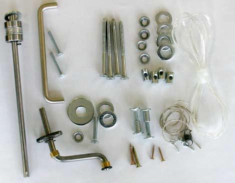
5 Fantasia Parts

6 Below is some information from the November 2005 issue of American Woodworker. This is just one way to proceed with a Fantasia that is unfinished if you want to paint your spinning wheel. The important step is to seal the MDF and in this example they are suggesting an oil based spray shellac. This is a good sealer for any wood in addition to MDF.
Kromski Interlude. Assembly Instructions
 Kromski Interlude Assembly Instructions Important Notice If you have any difficulty in understanding these instructions, assembling the wheel, or having it operate to its fullest potential, WE WANT YOU
Kromski Prelude. Assembly Instructions
 Kromski Prelude Assembly Instructions Important Notice If you have any difficulty in understanding these instructions, assembling the wheel, or having it operate to its fullest potential, WE WANT YOU TO
Kromski Symphony Assembly Instructions
 Kromski Symphony Assembly Instructions Important Notice If you have any difficulty in understanding these instructions, assembling the wheel, or having it operate to its fullest potential, WE WANT YOU
Kromski Minstrel Assembly Instructions
 Kromski Minstrel Assembly Instructions Important Notice If you have any difficulty in understanding these instructions, assembling the wheel, or having it operate to its fullest potential, WE WANT YOU
S10C. Instructions. Version S10C-V1c
 S10C Instructions Version S10C-V1c To celebrate our fortieth anniversary, we have transformed the spinning wheel it all started with: the S10. The new S10 Concept spinning wheel makes it possible to customize
ASHFORD COUNTRY SPINNER 2
 INSTRUCTIONS ASHFORD COUNTRY SPINNER 2 CS110618V8 Ashford Handicrafts Limited Factory and Showroom: 415 West Street PO Box 474, Ashburton 7700 New Zealand Telephone 64 3 308 9087 Facsimile 64 3 308 8664
JOY 2 SPINNING WHEEL
 INSTRUCTIONS JOY 2 SPINNING WHEEL SINGLE & DOUBLE TREADLE WITH A SLIDING HOOK FLYER JASW110618V8 Ashford Handicrafts Limited Factory and Showroom: 415 West Street PO Box 474, Ashburton 7700 New Zealand
KIWI 2 SPINNING WHEEL
 INSTRUCTIONS KIWI 2 SPINNING WHEEL KSWII19022016V7 Ashford Handicrafts Limited Factory and Showroom: 415 West Street PO Box 474, Ashburton 7700 New Zealand Telephone 64 3 308 9087 Facsimile 64 3 308 8664
ELIZABETH 30 SPINNING WHEEL
 INSTRUCTIONS ELIZABETH 30 SPINNING WHEEL Single and Double Treadle Ashford Handicrafts Ltd. Factory and Showroom: 415 West Street, PO Box 474, Ashburton, New Zealand Telephone 64 3 308 9087 Facsimile 64
WOLF PUP LOOM TM & WOLF PUP LT LOOM TM
 WOLF PUP LOOM TM & WOLF PUP LT LOOM TM Assembly Instructions FL3000 FL3006 FL3009 WOLF PUP WOLF PUP LT Find out more at schachtspindle.com Schacht Spindle Company 6101 Ben Place Boulder, CO 80301 p. 303.442.3212
BABY WOLF LOOM. Assembly Instructions for Knocked-Down Looms
 BABY WOLF LOOM Assembly Instructions for Knocked-Down Looms BEFORE YOU BEGIN Please read through the directions before beginning to assemble your loom. Unpack the loom parts carefully. Do not throw away
MATCHLESS DOUBLE TREADLE SPINNING WHEEL INSTRUCTIONS, MAINTENANCE
 MATCHLESS DOUBLE TREADLE SPINNING WHEEL INSTRUCTIONS, MAINTENANCE & WARRANTY Find out more at schachtspindle.com Schacht Spindle Company 6101 Ben Place Boulder, CO 80301 p. 303.442.3212 f. 303.447.9273
Side Winder R o u t e r L i f t.
 Woodpeckers PRECISION WOODWORKING TOOLS Side Winder R o u t e r L i f t. INSTALLATION INSTRUCTIONS The wrench handle must be pointing left in order to fully insert or remove it. Lift Wrench Once fully
Electric Skein Winder
 Electric Skein Winder Assembly and Use Package Contents 1 - Triangular Body (w/ motor) 1 - Cross Arm 1 - Left Foot (w/ yarn guide) 1 - Right Foot 1 - Adjustable Finger (w/ yarn clip) 3 - Adjustable Fingers
JOY SPINNING WHEEL SINGLE & DOUBLE TREADLE WITH A SLIDING HOOK FLYER
 INSTRUCTIONS JOY SPINNING WHEEL SINGLE & DOUBLE TREADLE WITH A SLIDING HOOK FLYER Ashford Hicrafts Ltd. Factory Showroom: 45 West Street, PO Box 474, Ashburton, New Zeal Telephone 64 0 907 Facsimile 64
Your new. Rose. spinning wheel. majacraft. all you need to spin your dreams... majacraft
 Your new Rose spinning wheel all you need to spin your dreams... 1 Welcome to the Majacraft family Congratulations on purchasing a new Majacraft Rose. We are very proud of this wheel and hope that it allows
ASHFORD TRADITIONAL SPINNING WHEEL SINGLE DRIVE
 INSTRUCTIONS ASHFORD TRADITIONAL SPINNING WHEEL SINGLE DRIVE TDSW110618V11 Ashford Handicrafts Limited Factory and Showroom: 415 West Street PO Box 474, Ashburton 7700 New Zealand Telephone 64 3 308 9087
WOLF LOOM DOUBLE BACK BEAM
 WOLF LOOM DOUBLE BACK BEAM Assembly Instructions Find out more at schachtspindle.com Schacht Spindle Company 6101 Ben Place Boulder, CO 80301 p. 303.442.3212 f. 303.447.9273 2017 Schacht Spindle Company,
Installation instructions for FC9 & FC18 Forward Controls for Yamaha V-Max
 Installation instructions for FC9 & FC18 Forward Controls for 1985-2007 Yamaha V-Max It is highly recommended that you use a thread lock compound such as Loctite brand on all threads to keep them from
It is highly recommended that you use a thread lock compound such as Loctite brand on all threads to keep them from vibrating loose.
 Installation instructions for FC12 Forward Controls for Kawasaki Vulcan 750 It is highly recommended that you use a thread lock compound such as Loctite brand on all threads to keep them from vibrating
mila-wall (Series100) General Operating Instructions page 1 of 15
 General Operating Instructions page 1 of 15") mila-wall (Series100) General Operating Instructions page 1 of 15 Step #1: Before setting up walls, lower adjustable leveling feet on each panel approximately 1". This will allow access to the threaded
mila-wall (Series100) General Operating Instructions page 1 of 15 Step #1: Before setting up walls, lower adjustable leveling feet on each panel approximately 1". This will allow access to the threaded
Nancy s Knit Knacks LLC 4 Yard Option Upgrade Kit Assembly Instructions and User Manual
 Nancy s Knit Knacks LLC 4 Yard Option Upgrade Kit Assembly Instructions and User Manual Thank you for purchasing our 4 Yard Option (4YO) Upgrade Kit. To install this upgrade you are simply going to assemble
Q-Zone Hoop-Frame. Assembly Instructions. Copyright July 11, 2018 Grace Company (Reproduction Prohibited) Version 1.8
 Version 1.8") Q-Zone Hoop-Frame Assembly Instructions Copyright July 11, 2018 Grace Company (Reproduction Prohibited) Version 1.8 Table of Contents Table of Contents... i Warranty... ii Parts List Box 1...iii Box 2...
Q-Zone Hoop-Frame Assembly Instructions Copyright July 11, 2018 Grace Company (Reproduction Prohibited) Version 1.8 Table of Contents Table of Contents... i Warranty... ii Parts List Box 1...iii Box 2...
Baby Grande or Grande Crank Shade with Cables and Housing Installation Instructions
 Baby Grande or Grande Crank Shade with Cables and Housing Installation Instructions Tools Needed Drill 3/8 Metal Drill Bit Screwdriver (Flat & Phillips) Measuring Tape Pencil 4 Level Plumb Line ¼ Masonry
Removing and Replacing the Y-truck
 Service Documentation Removing and Replacing the Y-truck To remove and replace the Y-truck you will need the following tools: 4mm Allen wrench 12mm stamped flat wrench #2 Phillips screwdriver (magnetic
MACHINE QUILTING FRAME
 MACHINE QUILTING FRAME YOU WILL NEED TO PURCHASE: 5 pieces of 1-1/4 thin wall metal conduit (EMT) cut to your preferred length for the rollers. (Maximum 120 ) DETERMINING YOUR ROLLER LENGTH: Determine
Matchless Single Treadle Spinning Wheel instructions, maintenance
 Matchless Single Treadle Spinning Wheel instructions, maintenance & warranty 49 24 0 70 Find out more at schachtspindle.com Schacht Spindle Company 6101 Ben Place Boulder, CO 80301 p. 303.442.3212 f. 303.447.9273
SCHACHT STANDARD FLOOR LOOMTM
 SCHACHT STANDARD FLOOR LOOMTM FL3109 FL3111 FL3113 FL3115 FL3121 FL3123 FL3125 FL3127 FL3310 FL3312 FL3314 FL3316 FL3322 FL3324 FL3326 FL3328 Assembly instructions LOW CASTLE LOOM IN MAPLE Find out more
Installation instructions for FC14S Forward Controls for Shadow ACE and Aero 1100
 Installation instructions for FC14S Forward Controls for Shadow ACE and Aero 1100 It is highly recommended that you use a thread lock compound such as Loctite brand on all threads to keep them from vibrating
Installation instructions for FC17 Forward Controls for Triumph Rocket III Roadster
 Installation instructions for FC17 Forward Controls for Triumph Rocket III Roadster It is highly recommended that you use a thread lock compound such as Loctite brand on all threads to keep them from vibrating
INSTRUCTION BOOKLET #34. For Wallbed models: KING SIZE SIERRA WITH STORAGE HEADBOARD
 For Wallbed models: KING SIZE SIERRA WITH STORAGE HEADBOARD INSTRUCTION BOOKLET #34 WARNING! ALL MURPHY/WALLBED SYSTEMS CONTAIN STORED ENERGY. FAILURE TO USE AND FOLLOW THESE INSTRUCTIONS DURING THE INSTALLATION
Hardware and Components:
 Hardware and Components: (A) 5/16 x 2 Hex Bolt (B) 5/16 x 2-1/4 Hex Bolt (C) 5/16 x 2-1/2 Hex Bolt (D) 4X 5/16 x 3/4 Hex Bolt (E) 4X 5/16 x 1-1/4 Hex Bolt (F) 11X 5/16 Flat Washer (G) 12X 5/16 Nylock Nut
2. Stand mainframe upright and cut bungee cord tie strap.
 2 3 1. Remove the seat rail from the main frame by first removing vertical frame tensioning bolt and the lower seat rail to main frame bolt as shown. Remove the entire seat rail/footplate assembly from
Hardware and Components:
 Hardware and Components: (A) 4X 5/16 x 1 Carriage Bolt (B) 2X 5/16 x 2-1/4 Carriage Bolt (C) 2X 5/16 x 3-1/4 Hex Bolt (D) 2X 5/16 x 3/4 Hex Bolt (E) 2X 5/16 x 1-1/4 Hex Bolt (F) 5/16 x 2-1/4 Hex Bolt (G)
Replacing the Reciprocator on the SWF Compact Series Machine (601C and 1201C)
") Follow the instructions below to replace the reciprocator in the SWF Compact series machines. The tools required can be found in the tool kit that came with the machine. Preparation 1. First, place the
Follow the instructions below to replace the reciprocator in the SWF Compact series machines. The tools required can be found in the tool kit that came with the machine. Preparation 1. First, place the
Replacement of Pitch Link Retainer and Service Improvement of the Pitch Control System. Effectivity: Helicopters manufactured prior to January, 1981
 Page 1 of 12 Date: December 2, 1981 Subject: Models: Replacement of Pitch Link Retainer and Service Improvement of the Pitch Control System F-28C and 280C Effectivity: Helicopters manufactured prior to
Instructions for Prepping an Opening for SOSS Invisible Hinges
 Instructions for Prepping an Opening for SOSS Invisible Hinges IMPORTANT Use only Porter-Cable Template Guide Bushing #42024 (Lock Face Routing) and #42237 (Lock Nut) to assure the following guide bushing
JVice Care and Maintenance Thanks for purchasing a Jvice. If properly looked after your Jvice will give a lifetime of tying pleasure.
 JVice Care and Maintenance Thanks for purchasing a Jvice. If properly looked after your Jvice will give a lifetime of tying pleasure. Although it is manufactured from highest quality materials any metal
FLIP TARP SINGLE & DOUBLE UNDERBODY TRAILERS
 1-800-248-7717 1002 N. 15th Street, Middlesboro, KY 40965 FLIP TARP SINGLE & DOUBLE UNDERBODY TRAILERS INSTALLATION INSTRUCTIONS Congratulations on your purchase of a Mountain Flip Tarp Trailer system.
WILDING WALLBEDS INSTALLATION INSTRUCTION Side Mount
 WILDING WALLBEDS INSTALLATION INSTRUCTION Side Mount For Wallbed models: Do-It-Yourself Insturction booklet C92 WARNING! ALL MURPHY/WALLBED SYSTEMS CONTAIN STORED ENERGY. FAILURE TO USE AND FOLLOW THESE
Side Mount INSTRUCTION BOOKLET #C122 BED STYLE: PARK CITY
 Side Mount BED STYLE: PARK CITY INSTRUCTION BOOKLET #C1 WARNING! ALL MURPHY/WALLBED SYSTEMS CONTAIN STORED ENERGY. FAILURE TO USE AND FOLLOW THESE INSTRUCTIONS DURING THE INSTALLATION PROCESS COULD RESULT
LEG CURL IP-S1315 INSTALLATION INSTRUCTIONS
 LEG CURL IP-S35 INSTALLATION INSTRUCTIONS Copyright 2009. Star Trac by Unisen, Inc. All rights reserved, including those to reproduce this book or parts thereof in any form without first obtaining written
Baby Grande or Grande Crank Shade with Cables and Housing Installation Instructions
 Baby Grande or Grande Crank Shade with Cables and Housing Installation Instructions Tools Needed Drill 3/8 Metal Drill Bit Screwdriver (Flat & Phillips) Measuring Tape Pencil 4 Level Plumb Line ¼ Masonry
The Bowflex Revolution XP Home Gym Assembly Instructions. P/N: Rev ( /0 )
") P/N: 001-7057 Rev ( /0 ) The Bowflex Revolution XP Home Gym Assembly Instructions 2 Table of Contents Before You Start... 2 Tools You Will Need / Hardware Contents... 3 Box Contents... 6 Assembling Your
P/N: 001-7057 Rev ( /0 ) The Bowflex Revolution XP Home Gym Assembly Instructions 2 Table of Contents Before You Start... 2 Tools You Will Need / Hardware Contents... 3 Box Contents... 6 Assembling Your
TM12 ASSEMBLY INSTRUCTIONS
 TM12 ASSEMBLY INSTRUCTIONS Congratulations on purchasing the finest purple martin house available. Nature House Brand houses are the proven leader in aluminum martin housing for over half a century. After
INSTALLATION INSTRUCTIONS
 INSTALLATION INSTRUCTIONS For Wallbed models: Do-It-Yourself BOOKLET #C90 WARNING! ALL MURPY/WALLBED SYSTEMS CONTAIN STORED ENERGY. FAILURE TO USE AND FOLLOW THESE INSTRUCTIONS DURING THE INSTALLATION
Installation And Care Instructions. Vertical Honeycomb Shades
 Installation And Care Instructions Vertical Honeycomb Shades Rev 5/2013 Table Of Contents Getting Started... 3 Parts Overview... 4 Materials Required... 5 Tools Required... 6 Outside Mount Installation...
INSPECTION AND CORRECTION OF BELLHOUSING TO CRANKSHAFT ALIGNMENT
 INSPECTION AND CORRECTION OF BELLHOUSING TO CRANKSHAFT ALIGNMENT BACKGROUND Proper alignment of the transmission input shaft to the crankshaft centerline is required in order to achieve the best results
Strata. urniture. Mission Rim Instructions. Parts in the Arm Box: Parts in the Body Box:
 1A Watch our assembly videos at www.strataf.com/videos.html Parts in the Arm Box: Arm - Outside View Arm - Inside View Corbels x 4 1B Parts in the Body Box: Back Deck x 1 Seat Deck x 1 with the Feet attached
#916 CLASSIC 16 GUN CABINET ASSEMBLY INSTRUCTIONS
 Thank you for purchasing this quality product. A list of PARTS and INSTRUCTIONS is included to assist you. Unpack and identify all parts included on the Parts List and Hardware List. If parts are missing,
INSTRUCTION BOOKLET #C21. For Wallbed models: KING SIZE
 For Wallbed models: KING SIZE INSTRUCTION BOOKLET #C1 WARNING! ALL MURPHY/WALLBED SYSTEMS CONTAIN STORED ENERGY. FAILURE TO USE AND FOLLOW THESE INSTRUCTIONS DURING THE INSTALLATION PROCESS COULD RESULT
Due to possible damage in shipping, the vertical stop assembly has been removed from this machine.
 Due to possible damage in shipping, the vertical stop assembly has been removed from this machine. To assemble, insert the threaded rod through the shroud opening in the top of the machine. Start the four
INSTALLATION AND CARE INSTRUCTIONS
 INSTALLATION AND CARE INSTRUCTIONS Vertical Applications Honeycomb Shades 52 C8-10-3401 Rev 2/14 CONTENTS Introduction...2 Before You Begin...3 Vertical Application Parts Overview...4 Materials Required...5
N. 15th Street, Middlesboro, KY FLIP TARP DUMP BODY INSTALLATION INSTRUCTIONS
 1-800-248-7717 1002 N. 15th Street, Middlesboro, KY 40965 FLIP TARP DUMP BODY INSTALLATION INSTRUCTIONS Congratulations on your purchase of a Mountain Flip Tarp Dump Body tarping system. With tarping systems
https://www.wallbedsbywilding.com/wallbed-installation-studio-series/
 For Wallbed models: KING SIZE INSTRUCTION BOOKLET #C1 Watch step by step installation instructions at: https://www.wallbedsbywilding.com/wallbed-installation-studio-series/ WARNING! ALL MURPHY/WALLBED
Strata. urniture. Adriana Instructions. Parts in the Arm Box: Parts in the Body Box: Watch our assembly videos at
 1A Watch our assembly videos at www.strataf.com/videos Parts in the Arm Box: Arm - Outside View Arm - Inside View 1B Parts in the Body Box: Back Deck x 1 Seat Deck x 1 with the Feet attached Back Panel
VARIABLE SPEED WOOD LATHE
 MODEL MC1100B VARIABLE SPEED WOOD LATHE INSTRUCTION MANUAL Please read and fully understand the instructions in this manual before operation. Keep this manual safe for future reference. Version: 2015.02.02
Before use please read & understand this manual, paying particular attention to the safety instructions.
 OPERATOR S MANUAL AND PARTS LIST 12 HAND PUSH ROLLER MOWER - THHMR Sales & Helpline 01793 333220 www.thehandy.co.uk Before use please read & understand this manual, paying particular attention to the safety
TRAILMATE METEOR ASSEMBLY MANUAL
 TRAILMATE METEOR ASSEMBLY MANUAL The Trailmate Meteor recumbent has been designed for easy assembly. This means more time to enjoy the smooth ride with single speed, 3 speed coaster brake and 21 speed
30DC Speed Lathe Manual
 30DC Speed Lathe Manual The Crozier Model 30DC Speed Lathe is our most popular model. It has many standard features not found on any other machine in its class or price range. Standard Features 3/4 HP
Instructions and Parts List DR-12N Martin House
 Form 36-99 Instructions and Parts List DR-N Martin House Note: It is necessary to install a post before house is put up, but the house can be assembled at any time. House parts Check parts against this
MOTORIZED STANDARD SHADE WITH CABLES Installation Instructions
 Tools Needed Drill Measuring Tape Pencil 2 Level Plumb Line ¼ Masonry Drill Bit Hammer Linesmans Pliers Cable Cutters Phillips & Flat-Head Screw Driver 11/32 Socket or Open End Wrench 5/32 Allen Wrench
The Queen Quilter Professional Quilters Kit Frame
 The Queen Quilter Professional Quilters Kit Frame Assembly Instructions Table of Contents: Before you begin......................... Pg. 2 Wood parts............................. Pg. 3 Hardware..............................
 INSTRUCTION BOOKLET #C10 Watch step by step installation instructions at: https://www.wallbedsbywilding.com/wallbed-installation-studio-series/ WARNING! ALL MURPHY/WALLBED SYSTEMS CONTAIN STORED ENERGY.
USSC LLC 4 ONE LLC FIELD MODIFICATION INSTRUCTIONS
 1 OF 17 A 1. PURPOSE: Instructions for in field replacement of 9004 mechanical suspension top pan 2. SCOPE: 9004 mechanical suspension with legacy two point LX back frame and current LX back frame 3. PROCEDURE:
Bushwacker Jeep Flat Style Fender Flares Front Pair
 Bushwacker Jeep Flat Style Fender Flares Front Pair Note: These instructions involve cutting parts of your vehicle. Please read all instructions prior to starting. Installation Time: 3-4 Hours Tools Required:
ULTRAFEED INDUSTRIAL TABLE PACKAGES Set-up Guide for #120931, # & #121091
 120932*1 Instructions for Sailrite Ultrafeed Industrial Table Packages ULTRFEE INUSTRIL TBLE PKGES Set-up Guide for #120931, #120934 & #121091 2 Ultrafeed Industrial Table Packages The Ultrafeed Industrial
3D PRINTER. Pack 11. Anything you can imagine, you can make! 3D technology is now available for you at home! BUILD YOUR OWN
 BUILD YOUR OWN Pack 11 Anything you can imagine, you can make! 3D PRINTER Compatible with Windows 7 & 8 Mac OS X 3D technology is now available for you at home! BUILD YOUR OWN 3D PRINTER CONTENTS PACK
Spinnit FMM3 Paper Drill
 Spinnit FMM3 Paper Drill Instruction Manual Provided By http://www.mybinding.com http://www.mybindingblog.com Before operating this equipment, please read these instructions completely and keep these operating
INSTALLING YOUR NEW SPRING LIFT ARM KIT
 INSTALLING YOUR NEW SPRING LIFT ARM KIT 1. Measure the distance that the roof is to be raised. [If your lift system is completely non-functional, you will need to calculate or estimate this distance as
LANDING GEAR. 1. Fit landing gear into slots on bottom of fuselage.
 LANDING GEAR 1. Fit landing gear into slots on bottom of fuselage. 4. Use channel-lock pliers to press blind nuts into position (note: drilled hole should be slightly smaller than shaft of blind nut for
POWER HONE OPERATION AND MAINTENANCE OF THE
 OPERATION AND MAINTENANCE OF THE POWER HONE TM M O D E L B The GRS Diamond Power Hone is designed for a long, useful service life. The spindle is driven by a smooth belt system at 240 RPM. The diamond
Gared Pro-S Portable Backstop
 Models: 9616 & 9618 Installation, Operation and Maintenance Instructions Please read all instructions before attempting installation or operation of these units SAVE THESE INSTRUCTIONS FOR FUTURE USE PUBLICATION
INSTRUCTION BOOKLET #C20
 INSTRUCTION BOOKLET #C0 WARNING! ALL MURPHY/WALLBED SYSTEMS CONTAIN STORED ENERGY. FAILURE TO USE AND FOLLOW THESE INSTRUCTIONS DURING THE INSTALLATION PROCESS COULD RESULT IN SEVERE PERSONAL INJURY TO
INSTALLATION AND CARE INSTRUCTIONS
 INSTALLATION AND CARE INSTRUCTIONS Vertical Applications Honeycomb Shades CONTENTS Introduction...2 Before You Begin...3 Vertical Application Parts Overview...4 Materials Required...5 Tools Required...6
The Phoenix. Professional Quilting Frame. Copyright January 1, 2016 Jim M. Bagley, GraceWood, Inc (Reproduction Prohibited) Version 2.
 Version 2.") The Phoenix Professional Quilting Frame Copyright January 1, 2016 Jim M. Bagley, GraceWood, Inc (Reproduction Prohibited) Version 2.1 1 The Phoenix Professional Quilting Frame Parts List Box 1...3 Box
The Phoenix Professional Quilting Frame Copyright January 1, 2016 Jim M. Bagley, GraceWood, Inc (Reproduction Prohibited) Version 2.1 1 The Phoenix Professional Quilting Frame Parts List Box 1...3 Box
Depending on the size you ordered you will have either 5 Foot sections which will build the 10 Foot frame or 6 Foot sections which will build the 12
 XL Quilting Frame 1 Depending on the size you ordered you will have either 5 Foot sections which will build the 10 Foot frame or 6 Foot sections which will build the 12 Foot frame Printed 2 June 2014 Updated
Basic steps to time the Gammill quilting machine s rotary sewing hook
 Basic steps to time the Gammill quilting machine s rotary sewing hook 1.) Turn the machine off and unplug it. 2.) With the needle bar in the raised position, remove the bobbin and bobbin case. 3.) Remove
White Quail Auto Trap
 White Quail Auto Trap WARNING SAFETY, STORAGE & USE IF THE MAIN SPRING IS ATTACHED AND THE TRAP ARM IS IN THE 6 O CLOCK POSITION, THE TRAP IS ARMED AND EXTREME CAUTION IS REQUIRED. TO DISARM, TURN THE
Strata. urniture. Addison Instructions. Parts in the Arm Box: Parts in the Body Box: Watch our assembly videos at
 1A Watch our assembly videos at www.strataf.com/videos.html Parts in the Arm Box: Arm - Outside View Arm - Inside View Corbels x 4 1B Parts in the Body Box: Back Deck x 1 Seat Deck x 1 Back Panel x 1 with
PORTABLE ADJUSTABLE BASKETBALL SYSTEM
 Instruction Manual PORTABLE ADJUSTABLE BASKETBALL SYSTEM P A R T S L I S T 5 1/2 and 8 safe play clearance Item Qty Description Item Qty Description A 1 Portable Base Assembly M 4 1/2 Lock Nut B 2 Front
ABM International, Inc. Navigator Assembly Manual
 ABM International, Inc. 1 1.0: Parts List Tablet (Qty. 1) Tablet mount (Qty. 1) NOTE: Mount may appear and operate different then image below Control Box (Qty. 1) Motor Power Supply (Qty. 1) 2 X-axis motor
HQ Pole Upgrade Kit for HQ Adjustable Table and HQ QuilTable Assembly Instructions 1
 HQ Pole Upgrade Kit for HQ Adjustable Table and HQ QuilTable Assembly Instructions QF09775 The pole upgrade kit can be used with or without the QF09700 HQ Precison-Glide track upgrade kit. What s Included
EXIT DEVICE OPERATION FIRE DOOR LABELS, STRIKES AND FRAME SCREWS FOR INFORMATION CALL OR VISIT RITEDOOR.COM
 RECORD & LABELS WHAT THIS OWNER'S CAN DO FOR YOU It explains exactly how The Rite Door operates. It explains periodic maintenance requirements necessary to assure reliable operation. It explains simple
18000 HDL FOUR POST LIFT LB CAPACITY INSTALLATION AND OWNER'S MANUAL
 18000 HDL FOUR POST LIFT 18000 LB CAPACITY INSTALLATION AND OWNER'S MANUAL WARNING! Do not raise a vehicle unless the front stops are in place, the parking brake is set, and the wheels are chocked. Stay
RIPPER PEDAL. Bearing / Axle Replacement. ( Disassembly )
") RIPPER PEDAL Bearing / Axle Replacement ( Disassembly ) 1 1. Use good quality tools to avoid stripping screw sockets. 2. When servicing your pedals, work on one side at a time to prevent parts from mixing
RIPPER PEDAL Bearing / Axle Replacement ( Disassembly ) 1 1. Use good quality tools to avoid stripping screw sockets. 2. When servicing your pedals, work on one side at a time to prevent parts from mixing
HDL(M)6 Nut/Screw Assembly
6 Nut/Screw Assembly") HDL(M)6 Nut/Screw Assembly Remove, repair, and reassemble the nut and screw assembly in your HDL series double lock vise. In these instructions when we refer to the front of the vise or nut/screw assembly,
HDL(M)6 Nut/Screw Assembly Remove, repair, and reassemble the nut and screw assembly in your HDL series double lock vise. In these instructions when we refer to the front of the vise or nut/screw assembly,
M2 Assembly. M2 Sub-Assemblies mm Belt Sub-Assembly mm Belt Sub-Assembly Spider Sub-Assembly... 4
 M2 Assembly Table of Contents M2 Sub-Assemblies... 3 630mm Belt Sub-Assembly... 3 702mm Belt Sub-Assembly... 3 Spider Sub-Assembly... 4 Idler Bolt Sub-Assembly... 8 Y Motor Sub-Assembly... 9 X Motor Sub-Assembly...
BRM * This item is for consumer use only and it is not meant for commercial use.
 BRM 10 * This item is for consumer use only and it is not meant for commercial use. OWNER S MANUAL General Information Safety Before you undertake any exercise program, please be sure to consult with your
SERVICE PARTS LIST. M18 FUEL SAWZALL Reciprocating Saw F56A BULLETIN NO CATALOG NO
 47(5x) 46 45 00 44 0 59 43 42 84 51 57 46 47 48 59 83 64 77 48 47(2x) 49(2x) 40 58 See service note on page 5 41 82 51 40 41 42 43 44 45 87 52 27 28 34 57 29 (6x) 60 28 EXAMPLE: Component Parts (Small
For additional assistance call
 The following pages will help guide you through the process of assembling your new 48 custom prize wheel. Choose an assembly area with plenty of room to lay your pieces on the floor and also a bench or
Original Gallery System
 GAllery System Art Displays Original Gallery System a Gallery System product Here s everything you need to know to get started with your Gallery System Art Hanging System GS getting started To install
SERIES I MILLING MACHINES
 INSTALLATION, OPERATION, MAINTENANCE, AND PARTS LIST SERIES I MILLING MACHINES TP5260 Revised: August 29, 2005 Manual No. M-450 Litho in U.S.A. Part No. M -0009500-0450 June, 2003 MAINTENANCE PROCEDURES
Tools Needed Hardware Provided (per shade) Hardware Needed
 Hardware Needed") Baby Grande or Grande Motorized (XQ5 Premium) Shade with Cables and Housing Installation Instructions Tools Needed Hardware Provided (per shade) Hardware Needed Drill 3/8 Metal Drill Bit Measuring Tape
Baby Grande or Grande Motorized (XQ5 Premium) Shade with Cables and Housing Installation Instructions Tools Needed Hardware Provided (per shade) Hardware Needed Drill 3/8 Metal Drill Bit Measuring Tape
REPAIR INSTRUCTIONS. Cat. No Cat. No MILWAUKEE ELECTRIC TOOL CORPORATION. SDS Max Demolition Hammer. SDS Max Rotary Hammer
 Cat. No. 9-0 SDS Max Demolition Hammer Cat. No. -0 SDS Max Rotary Hammer MILWAUKEE ELECTRIC TOOL CORPORATION W. LISBON ROAD BROOKFIELD, WISCONSIN 00-0 8-9-0 d 000 8-9-0 d Special Tools Require Forcing
Heavy Duty Mechanic s Kit
 Heavy Duty Mechanic s Kit 00 Safety Warning Read all instructions and safety warnings prior to operation. Failure to do so could result in equipment damage, personal injury or even death. CAUTION 00: FAILURE
This manual will aid in the assembly of the FireBall V90 and FireBall X90. The assembly of both machines will be identical, unless specified.
 This manual will aid in the assembly of the FireBall V90 and FireBall X90. The assembly of both machines will be identical, unless specified. Step #1 Lay all parts out to verify quantities. (2) 2 x 25-1/4
For Barrel Tapers. Installation and Operating Instructions for use with table saws and large disk sanders
 Tim s Taper Tool For Barrel Tapers Installation and Operating Instructions for use with table saws and large disk sanders Your taper tool is capable of making barrel tapered shafts. The term barrel is
ABM International, Inc.
 ABM International, Inc. Lightning Stitch required 1 1.0: Parts List head and motor assembly (Qty. 1) Reel stand (Qty. 1) Needle bar frame clamp (Qty. 1) Motor drive (Qty. 1) 2 Cable harness with bracket
Printrbot Simple (Model 1403) Rev F Printrboard
 Rev F Printrboard") Printrbot Simple (Model 1403) Rev F Printrboard Printrbot Simple is currently shipping with the Rev F Printrboard. Check which rev Printrboard your Simple kit includes and use the corresponding instructions.
Printrbot Simple (Model 1403) Rev F Printrboard Printrbot Simple is currently shipping with the Rev F Printrboard. Check which rev Printrboard your Simple kit includes and use the corresponding instructions.