FC3920K and FC5539K Automatic Foam Cutting CNC Machines
|
|
|
- Raymond James
- 6 years ago
- Views:
Transcription
1 FC3920K and FC5539K Automatic Foam Cutting CNC Machines Disclaimer You accept all risks and responsibilities for looses, damages costs and other consequences resulting directly or indirectly from using the automatic foam cutter. FoamLinx is not responsible for any damage or injury caused by the foam cutter or its parts during the assembly or the operation of the foam cutter. FoamLinx designed the machine to be as safe as possible, as long as you follow the assembly, operations instructions and common sense. If you find anything missing, please contact us immediately at or call us at Always keep away from all moving parts Never touch the hot wire, it may be hot and may also cause electrical shock Foam fumes are toxic always work in a well ventilated area Parts Most parts are exclusively fabricated for FoamLinx including metal parts and electronics. We try our best to keep the price of our machine to a minimum. In order to accomplish this task we sometime use excess inventory parts some motors may be used. All motors are fully tested prior to being packaged Warranty FoamLinx provides 3 months warranty on electronics and motors and life time warranty on all mechanics Training On-site training is available, for more information contact us at info@foamlinx.com
2 FC3920 Foam Cutting CNC machine Parts list FC Foam Cutting CNC machine Units Part Name 2 X axis motor mounts 2 X axis carriage 2 Y axis carriage 4 End mounts 8 Bearing support plates 4 ACME nuts 2 Spring 16 Washers 32 10/32 socket screw 16 10/32 nut 20 8/32 socket screw 16 8/32 nut 16 3/4" bearing 4 1/2" bearing 2 Eye hooks + 4 eye hook nuts 2 Alligator clips and cables 4 Motor couplers 4 Board spacers In Case 1 Electronic board In Case 1 4 wire cable In Case 4 High torque motors 1 Electronics power supply In Case 1 Electronics power supply cable In Case 1 Hot wire power supply - 250W In Case 1 Hot wire power supply cable In Case 1 Hot Wire 1 D25 cable 1 FoamWorks CD - Download 1 FoamLinx assembly manual CD - Jan 2005 Download 1 Temperature controller - 250W In Case 4 X axis rods - 55" long In Tubes 4 Y axis rods - 36" long In Tubes 2 X axis ACME threads In Tubes 2 Y axis ACME threads In Tubes FoamLinx assembly manual

3 Left X axis and Right Axis slides Locate the above parts needed for the right (or left) X axis slide The following parts are needed for the left X axis slide (same for the right slide) Number of parts Description Remarks 4 ¾ Bearing 1 ½ Bearing Placed on the End Mount 2 Bearing support plates 1 End Mount 1 Motor Mount 1 Acme Nut 10 8/32 Socket cap screws 2 for the Acme nut 8 8/32 Nuts


4 Assembly of the X axis carriage Screw in the ACME nut to one of the bearing support plates using the two 8/32 screws Screw in the bearing support plate to the X axis carriage with two 8/32 screws


5 Make sure that the wider side of the bearings face inward to the carriage as shown above. Insert the rods and make sure they slide freely.


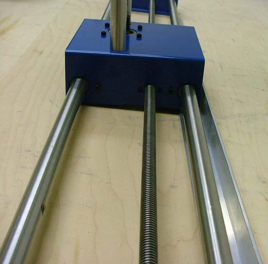
6 Bottom view of the X axis carriage


7 X Axis motor mount assembly Locate the Motor Mount, 4 pcs of 10/32 screws and nuts Mount the stepper motor inside the Motor Mount using 4 10/32 screws

8 Locate the End Mount and insert the ½ bearing as shown above. At this point the slide should be assembled. Adjustments: In order for the machine to reach highest cutting speeds, adjustments of the bearing support plates may be needed. The goal is to reach a point where the friction on the bearings is minimal. The lower the friction, the faster the machine can cut.

9 Using your fingers, move the coupler back and forth as shown in the red arrows above. The movement should be smooth. If the movement is not smooth, loosen the 4 bearing support plate screws and try moving the coupler. While moving the coupler, tighten the screws one by one, making sure the movement continues to be smooth.

10 Y-axis Carriage assembly Locate the Y-axis carriage (it should have 9 holes on its front face) Assemble the bearing support plates same as for the X-axis carriage. Note: the plastic bearings have a larger side, this side faces the inside of the carriage

11 Another view of the Y axis carriage this time showing the ACME nut


12 Locate the End mount shown on the left of the image below Insert the two shafts through the Y-axis carriage. Screw in the ACME screw as shown below Mount the new slide on top of the X-axis carriage as shown above

13 The ACME nut can be at the top of the carriage as well, both locations will work.
 And at the bottom Assemble the")
14 Side view of the Y-axis slide mounted on top of the X-axis carriage. At this point, tighten the two screws on the top (on the End Mount) And at the bottom Assemble the 2 nd XY system same as the 1 st.


15 Glue the square Teflon pads to the bottom of the X-axis carriage The Teflon pads glide on top of the L shape Aluminum channel as shown below
16
17 Foamworks Software setup Download and install 2 programs from #1 CadWorks, #2 FoamWorks **Restart computer** Open FoamWorks. Click on Setup Machine (on the left side) Set Lead-in Cut Options>Amount Inches to 0 Set Stepper Motor Options to Check Reverse X1 Direction Check Reverse X2 Direction Under Machine Setup set the Pins as follows. (Assume 1 designates LEFT and 2 designates RIGHT, ie X1 = X Left, X2 = X Right ) X1 Direction = Pin 4, X1 Step = Pin 5, Y1 Direction = Pin 2, Y1 Step = Pin 3, X2 Direction = Pin 8, X2 Step = Pin 9, Y2 Direction = Pin 6, Y2 Step = Pin 7, Click DONE (top of screen) **Plug in the Controller s Power Supply cord** Look at Manual Control (on the left side). This gives you several manual modes to run the X and Y axis for testing and adjusting the support plates on the X and Y Carriages. Confirm that the commands drive the hot wire in the correct direction by using the Single Axis control. Forward: drives the wire away from you and Back drives the wire back toward you.
18 TUTORIAL The following tutorial will lead you through cutting your first shape. Cut a 4 foot tapered architectural column, with a 6 d top and 8 d bottom. This exercise assumes you start with an 4' tapered rectilinear cube of foam, one end 6" x 6"on the left, the other 8" x 8" on the right, positioned left to right between the left and right X/Y towers. You have also used FoamWorks to drive the hot wire into position along its length touching the foam at a 3:00 position looking at the left 6" x 6" end. Open CadWorks 1 - File>New (starts a new drawing) Draw a circle of any diameter (select circle icon in left menu) 2 - CNC Tools>Prep Drawing 3 - CNC Tools>Generate DAT File from Sequential Drawing 4 - File>Save>DAT File (save as circle.dat) Open FoamWorks Prepare the Machine Manually drive the hot wire to a position midway top to bottom and about 10 back from the front of the machine. 1 - Foam Cutter>Generate Cut File (bottom left of window) Locate and load circle.dat for both Left and Right Cutting Towers. Set Left Horizontal Size to 6 (inches), Set Right Horizontal Size to 8 (inches) 2 - Generate Cut File (press generate button, top left of window) 3 - Save Cut File (Circle.ct1) 4 - Done (top right hand corner) 5 - Foam Cutter>Start Cut, Cutting Speed Adjustment (Move slider half way to the right)
19 6 - Begin Cut (upper left hand corner) Note: You can visualize the cutting action of any item you draw by walking around to the left hand side of the machine and by looking at the X/Y axis. This is the view that will be represented in the FoamWorks cutting window. Watch as the line segments turn red indication cutting progress.

20 DeskCNC software DeskCNC software enables the user to get more out of the machine Higher speeds Multiple shapes on one piece of foam Cuts directly from DXF DeskCNC can be downloaded from this link: To run DeskCNC you will need the 2 nd generation controller board. The board connects to the PC via the serial cable (9 pin cable) On the other side of the board, a 25-pin cable hooks up to the PC. It doesn t matter which software you use, the 25-pin cable is always connected to the Blue box. DeskCNC is set by default to run a 3-axis CNC router table. In order to set it for a 4-axis foam cutter please follow the steps below Click on Setup, then Machine 1. Click on the 4 Axis 2. Click on the Linear A Axis 3. Click Save

21 Make sure that all 4 axis are set to 4000 steps per inch Click Save At this point the machine should be 4 axis operational. In order to test all 4 axis you will need to manually control each axis.


22 Make sure that acceleration is set to max and follow the same values as in the screen shot below Click on Setup and choose the Options as shown above

23 In the Options window click on the Misc tab and choose the FourAxisLinear Option for the Post processor as indicated by the read arrow above. Click on save

24 Click on machine and you should see the screen above. X and Y are Left X and left Y Z is really Right X A is really Right Y Click on the Reset button and you are now ready to move each axis. Click on the X+ button and the X motor should move. To run the motor faster, click on the Jog -> Slow pull down menu And change it to medium, then click on the X+ button Below are a few tutorials from the DeskCNC web site
Legacy Woodworking Machinery a division of Phantom Engineering. The Legacy CNC. Assembly Manual
 Legacy Woodworking Machinery a division of Phantom Engineering The Legacy CNC Assembly Manual New Orientation of the Legacy Step one: Re-orientation of the machine Remove the X-axis screw and supports.
The Phoenix. Professional Quilting Frame. Copyright January 1, 2016 Jim M. Bagley, GraceWood, Inc (Reproduction Prohibited) Version 2.
 Version 2.") The Phoenix Professional Quilting Frame Copyright January 1, 2016 Jim M. Bagley, GraceWood, Inc (Reproduction Prohibited) Version 2.1 1 The Phoenix Professional Quilting Frame Parts List Box 1...3 Box
The Phoenix Professional Quilting Frame Copyright January 1, 2016 Jim M. Bagley, GraceWood, Inc (Reproduction Prohibited) Version 2.1 1 The Phoenix Professional Quilting Frame Parts List Box 1...3 Box
AX1001. Smith/Functional training Combo-free weight ASSEMBLY INSTRUCTIONS
 AX1001 Smith/Functional training Combo-free weight ASSEMBLY INSTRUCTIONS EXPLODED DIAGRAM 83 84 84 85/86 87 87 88 89 90 91 62 64 64 64 64 64 64 65 65 65 65 66 66 65 66 66 65 63 63 66 67 68 55 66 66 70
Electric Skein Winder
 Electric Skein Winder Assembly and Use Package Contents 1 - Triangular Body (w/ motor) 1 - Cross Arm 1 - Left Foot (w/ yarn guide) 1 - Right Foot 1 - Adjustable Finger (w/ yarn clip) 3 - Adjustable Fingers
Elimination of Elevator Bounce
 For the Agilent Archon Autosampler Rework Instructions CAUTION This kit is intended for use by Agilent Service personnel only. Elevator Removal 1 Open top cover. 2 Open front lower door. 3 Remove vial
Depending on the size you ordered you will have either 5 Foot sections which will build the 10 Foot frame or 6 Foot sections which will build the 12
 XL Quilting Frame 1 Depending on the size you ordered you will have either 5 Foot sections which will build the 10 Foot frame or 6 Foot sections which will build the 12 Foot frame Printed 2 June 2014 Updated
Vinyl Cutter Instruction Manual
 Vinyl Cutter Instruction Manual 1 Product Inventory Inventory Here is a list of items you will receive with your vinyl cutter: Product components (Fig.1-4): 1x Cutter head unit complete with motor, plastic
GENMITSU CNC ROUTER 3018 USER MANUAL
 GENMITSU CNC ROUTER 308 USER MANUAL Part : Package List Name Size Picture Qty Aluminum 220mm 360mm 330mm Mesa 2 5 2 Corner connector Slide nut Axis support base Linear axis Lead screw 2028 20M5 30M5 SK0
(Assembling Guide supplied by imakr ) with the support of MyMiniFactory.com
 with the support of MyMiniFactory.com") (Assembling Guide supplied by imakr ) with the support of MyMiniFactory.com Summary Congratulations on beginning on your journey into 3D printing with the STARTT 3D printer. In this guide, you will have
(Assembling Guide supplied by imakr ) with the support of MyMiniFactory.com Summary Congratulations on beginning on your journey into 3D printing with the STARTT 3D printer. In this guide, you will have
AM8 Printer A metal frame for your Anet A8 By Pheneeny v1.0 April 20, 2017
 AM8 Printer A metal frame for your Anet A8 By Pheneeny v1.0 April 20, 2017 Please read this entire document before printing parts or building this frame Disclaimer: This guide is for informational purposes
LEG CURL IP-S1315 INSTALLATION INSTRUCTIONS
 LEG CURL IP-S35 INSTALLATION INSTRUCTIONS Copyright 2009. Star Trac by Unisen, Inc. All rights reserved, including those to reproduce this book or parts thereof in any form without first obtaining written
Installing a 3 Indexer: Desktop Tools
 888-680-4466 ShopBotTools.com Installing a 3 Indexer: Desktop Tools built after October, 2012 Copyright 2016 ShopBot Tools, Inc. page 1 Copyright 2016 ShopBot Tools, Inc. page 2 Table of Contents Overview...5
GoPro Hero Camera Mount. Assembly Manual
 GoPro Hero Camera Mount Assembly Manual Introduction Thank you for purchasing the GoPro Hero Camera Mount for Mikrokopter Quad, Hexa and Okto. The Camera Mount is provided as a kit and requires assembly.
Written By: Brook Drumm
 Simple 1401 Assembly For kits produced between 1/15/14-6/1/14. This guide is for kits with the Fan Shroud. Instructions for metal and wood extruder (and bed) included below. Written By: Brook Drumm TOOLS:
Customer Notice: Congratulations again on your SawStop purchase, and thank you! -SawStop Tualatin, OR
 Customer Notice: Congratulations on the purchase of this Sliding Crosscut Attachment. As the owner of a SawStop saw, you are familiar with our high standards for quality, fit and finish. Different from
Cap frame (Shaft-less type)
") Cap frame (Shaft-less type) Installation manual ** Model : XT-CAII / XT-CBII / XT-CII / XY-CII / XS-C ** 1: Wide cap frame -------------------------------------------------------------Page 2 2: Semi-wide
Cap frame (Shaft-less type) Installation manual ** Model : XT-CAII / XT-CBII / XT-CII / XY-CII / XS-C ** 1: Wide cap frame -------------------------------------------------------------Page 2 2: Semi-wide
Hardware and Components:
 Hardware and Components: (A) 5/16 x 2 Hex Bolt (B) 5/16 x 2-1/4 Hex Bolt (C) 5/16 x 2-1/2 Hex Bolt (D) 4X 5/16 x 3/4 Hex Bolt (E) 4X 5/16 x 1-1/4 Hex Bolt (F) 11X 5/16 Flat Washer (G) 12X 5/16 Nylock Nut
MAIN PARTS
 MAIN PARTS 7 8 9 10 11 12 13 1 2 3 17 4 5 6 01 02 03 04 05 12 23 34 45 56 13 24 35 46 57 14 25 36 47 58 15 16 26 27 37 38 48 49 59 60 06 07 08 09 10 17 18 28 29 39 40 50 51 61 62 19 30 41 52 63 20 21 31
Star Trac Turbo Trainer Assembly & Setup
 Star Trac Turbo Trainer Use the following procedures to unpack and assemble your Turbo Trainer manufactured by Star Trac. UNPACKING AND PARTS LIST Position the shipping carton so the Heavy End logo is
Sliding Crosscut Table installation guide
 Sliding Crosscut Table installation guide model tsa-sa48 A Note About Color Variations Among Anodized Aluminum Components Congratulations on the purchase of this SawStop Sliding Crosscut Table. We at SawStop
Shapeoko XXL Assembly Guide
 Shapeoko XXL Assembly Guide 04/27/2016 XXL Packing LIst Item Qty Description Y-Carriage (left) 1 Y-Carriage (right) 1 X/Z Assembly 1 40 Rail 3 1 rail has mounting holes for controller Wasteboard Half 2
Lead Screw Upgrade. How to upgrade your ROBO R1 to the new Lead Screw Upgrade Pack. Written By: Harrison Team RoBo 3D
 Lead Screw Upgrade How to upgrade your ROBO R1 to the new Lead Screw Upgrade Pack. Written By: Harrison Team RoBo 3D 2017 guide.robo3d.com Page 1 of 14 Step 1 Lead Screw Upgrade Begin by powering off and
Hardware and Components:
 Hardware and Components: (A) 4X 5/16 x 1 Carriage Bolt (B) 2X 5/16 x 2-1/4 Carriage Bolt (C) 2X 5/16 x 3-1/4 Hex Bolt (D) 2X 5/16 x 3/4 Hex Bolt (E) 2X 5/16 x 1-1/4 Hex Bolt (F) 5/16 x 2-1/4 Hex Bolt (G)
ABM International, Inc. Navigator Assembly Manual
 ABM International, Inc. 1 1.0: Parts List Tablet (Qty. 1) Tablet mount (Qty. 1) NOTE: Mount may appear and operate different then image below Control Box (Qty. 1) Motor Power Supply (Qty. 1) 2 X-axis motor
FoamWorks Introduction. David Mrozinski 848 W. Borton Road Essexville, Michigan 48732
 FoamWorks 4.0 Introduction Quick Start Registration Registration Menus Files Save a Cut Profile Load a Cut Profile Close Profile/G-code Restore Default Cut Profile Exit Setup Setup Parameters Generate
Machine Quilting Frame assembly, and instruction manual
 Machine Quilting Frame assembly, and instruction manual Table of Contents Parts List................. Pg. 2 Step 1 - Legs............... Pg. 4 Step 2 - Lower Leg Brace....... Pg. 5 Step 3 - Frame Ends..........
Assembly Guide for Printrbot - Simple Maker s Edition 1405
 Assembly Guide for Printrbot - Simple Maker s Edition 1405 Last update: March 2016 Please Note: be careful on the steps that are underlined 1 Contents Tools Needed:... 3 First step: Check components and
model tsa-sa48 Sliding Crosscut Table installation guide
 model tsa-sa48 Sliding Crosscut Table installation guide A Note About Color Variations Among Anodized Aluminum Components Congratulations on the purchase of this SawStop Sliding Crosscut Table. We at SawStop
MOTORIZED STANDARD SHADE WITH CABLES Installation Instructions
 Tools Needed Drill Measuring Tape Pencil 2 Level Plumb Line ¼ Masonry Drill Bit Hammer Linesmans Pliers Cable Cutters Phillips & Flat-Head Screw Driver 11/32 Socket or Open End Wrench 5/32 Allen Wrench
This guide contains everything you need to set up and operate all three. Inspira Imperial Quilting Frame Assembly...2
 Congratulations on the purchase of your Husqvarna Viking Mega Quilter 18x8, Inspira Imperial Quilting Frame, and QBOT by Inspira! This guide contains everything you need to set up and operate all three.
Installing CNC Stepper Motor Mounts On A Sherline Mill
 Installing CNC Stepper Motor Mounts On A Sherline Mill P/N 6700 (6710 Metric) 5000/5100/5400/5410 Mills P/N 6705 (6715 Metric) 2000/2010 Mills USING THE TEMPLATE BLOCKS TO LOCATE NEW MOUNTING HOLES FOR
Removing the Z-Axis lead screw
 Page 1 of 8 TITLE: Sabre Z-Axis Lead Screw Replacement Procedure Gerber FastFact #: 5048 Supplied by: Gerber Hardware Support Last Modified: June 14, 2007 Summary: Tools used: The following procedure explains
DUAL ADJUSTABLE PULLEY IP-D9302 INSTALLATION INSTRUCTIONS
 DUAL ADJUSTABLE PULLEY IP-D9302 INSTALLATION INSTRUCTIONS Copyright 2010. Star Trac by Core Industries, Inc. All rights reserved, including those to reproduce this book or parts thereof in any form without
HQ Pole Upgrade Kit for HQ Adjustable Table and HQ QuilTable Assembly Instructions 1
 HQ Pole Upgrade Kit for HQ Adjustable Table and HQ QuilTable Assembly Instructions QF09775 The pole upgrade kit can be used with or without the QF09700 HQ Precison-Glide track upgrade kit. What s Included
Assembly procedure for KA_S series January, 04, 2010
 Assembly procedure for KA_S series January, 04, 2010 The following procedure is valid for KA060S and KA080S. However, only pictures of KA060S are shown as examples. The other is similar. 1. Examine specification
BABY WOLF LOOM. Assembly Instructions for Knocked-Down Looms
 BABY WOLF LOOM Assembly Instructions for Knocked-Down Looms BEFORE YOU BEGIN Please read through the directions before beginning to assemble your loom. Unpack the loom parts carefully. Do not throw away
MILL ONE. Assembly Manual. Manual Illustrated by Gontarz Design Studio
 MILL ONE Assembly Manual Manual Illustrated by Gontarz Design Studio Safety Warnings and Guidelines 1. Be sure to carefully follow provided machine assembly instructions before machine use to ensure operator
Installation Guide. English. English
 Installation Guide Safety Instructions For your safety, read all the instructions in this guide before using the setting plate. Incorrect handling that ignores instructions in this guide could damage the
Model 209 Fireback Replacement
 Model 209 Fireback Replacement Please read all the instructions before you begin the procedure. Confirm that you have all the necessary tools and materials. If you have any questions, technical support
E3 CNC Router Assembly Instructions
 E3 CNC Router Assembly Instructions Specifications... 3 Getting Started... 3 Safety First... 3 Required Tools... 4 Building the E3 CNC Engraver... 4 1. Z Spindle Mount Assembly... 5 3. Frame Assembly...
CRP700 Benchtop Basic CNC Machine Assembly Instructions. Updated 9/11/2014 SHEET 1 of 25
 CRP700 Benchtop Basic CNC Machine Assembly Instructions Updated 9//0 SHEET of NOTE: This piece of extrusion is mounted wide side up Quick Tip: Lay extrusion on table as shown for easy assembly BASE ASSEMBLY:.
CNC Router Parts. Standard Rack & Pinion Drive Assembly Instructions
 CNC Router Parts Standard Rack & Pinion Drive Tools List The following tools will be used for assembly and installation of the Standard Rack & Pinion Drive: Imperial Allen Wrench Set - 3/32", 5/32", 3/16",
Installing the 3 Indexer: PRS Standard Tools
 888-680-4466 ShopBotTools.com Installing the 3 Indexer: PRS Standard Tools Copyright 2016 ShopBot Tools, Inc. page 1 Copyright 2016 ShopBot Tools, Inc. page 2 Table of Contents Route Cable into Box...5
Installing CNC Stepper Motor Mounts On A Sherline Lathe
 Installing CNC Stepper Motor Mounts On A Sherline Lathe P/N 6720 (6725 Metric) 4000/4100/4500/4600 Lathes P/N 6730 (6735 Metric) 4400/4410 Lathe USING THE TEMPLATE BLOCKS TO LOCATE NEW MOUNTING HOLES FOR
This manual will aid in the assembly of the FireBall V90 and FireBall X90. The assembly of both machines will be identical, unless specified.
 This manual will aid in the assembly of the FireBall V90 and FireBall X90. The assembly of both machines will be identical, unless specified. Step #1 Lay all parts out to verify quantities. (2) 2 x 25-1/4
Installing the Partridge RA Extension on Losmandy G11
 Installing the Partridge RA Extension on Losmandy G11 Michael Herman July 20, 2015 Tools: 3/16 inch hex key (allen wrench) [If desired for DEC indicator ring friction improvement: flat screwdriver, and
Nancy s Knit Knacks LLC 4 Yard Option Upgrade Kit Assembly Instructions and User Manual
 Nancy s Knit Knacks LLC 4 Yard Option Upgrade Kit Assembly Instructions and User Manual Thank you for purchasing our 4 Yard Option (4YO) Upgrade Kit. To install this upgrade you are simply going to assemble
TITAN2-EDGE Public Access Computer Station Dual Track
 TITAN2-EDGE Public Access Computer Station Dual Track TITAN2-EDGE Rev A 6/17 Model TITAN2-EDGE ASSEMBLY AND ADJUSTMENT TITAN2-EDGE PARTS AND TOOLS PLEASE REVIEW these instructions before beginning the
Arc Trainer Main Frame Assembly
 Arc Trainer Main Frame Assembly Kit No. 610AK019-4 Kit No. 630AK019-4 NOTE: This instruction sheet describes how to replace the main frame assembly in the Arc Trainer 610A. Tools Required 3/16 Allen wrench
DIFFUSION MODULAR ENLARGER
 DIFFUSION MODULAR ENLARGER MODEL fh-52 INSTRUCTION MANUAL 3684-OO05 Thank you for your having selected an LPL enlarger. Please read this manual carefully before using the enlarger, and keep it for future
9.07 KINEMATICS KIT USERS MANUAL
 9.07 KINEMATICS KIT USERS MANUAL INCLUDED PARTS LIST Standard parts - 1. ground plane enclosure which includes stepper motor with control circuits, press fit motor shaft adaptor, and link attachment plate.
Standard Operating Procedure
 RIT MULTIDISCIPLINARY SENIOR DESIGN 2010 Standard Operating Procedure Baja Water Propulsion Test Stand This SOP specifies how to assemble, use, troubleshoot, and disassemble the water propulsion system
PRS Retro Z-Axis Installation
 PRS Retro Z-Axis Installation Page -1- PRS Retro Z-Axis Installation This document is a guide to installing the PRS Retro Z-axis on early ShopBot models. It describes installation for PR models with PK299
Serial Number Location
 GL/GLX STRENGTH TRAINING SYSTEM OWNERS MANUAL Serial Number Location SERIAL 3 4 5 7 8 Record your Serial number and purchase date here: S/N DATE: DEALER: Model No. BCG-GL BODYCRAFT is a division of Recreation
Ohbot. Eyes turn. servo. Eyelids open. servo. Head tilt. servo Eyes tilt. servo. Mouth open servo. Head turn servo
 Making Instructions Ohbot Ohbot has six servo motors. The servos allow each part of the face to be positioned precisely. Eyelids open servo Eyes tilt servo Eyes turn servo Head tilt servo Mouth open servo
6MM ALLEN KEY FOR ROOF CLIPS PHILLIPS HEAD BIT FOR SCREWS FOR DOOR FRAME SPIRIT/LASER LEVEL TO LEVEL THE UNIT
 1 TOOLS REQUIRED: MOVING CART/DOLLY FOR TRANSPORTING PANELS, ROOF, AND POSTS TWO 9 FT. STEP LADDERS FOR INSTALLING ROOF & PANELS MINI REVERSIBLE RATCHET 1/4 DRIVE FOR CORNER SCREWS ON TOP TRAVERSE BEAMS
CRP700 Benchtop Basic CNC Machine Assembly Instructions. Updated 10/24/2014 SHEET 1 of 24
 CRP700 Benchtop Basic CNC Machine Assembly Instructions Updated 0//0 SHEET of NOTE: This piece of extrusion is mounted wide side up Quick Tip: Lay extrusion on table as shown for easy assembly BASE ASSEMBLY:.
V4 Premium Kit. Prusa i3 Build Guide
 V4 Premium Kit Prusa i3 Build Guide Hi! Congratulations on your purchase of the DIYElectronics.co.za Prusa I3 kit, the best South African 3D Printer Kit! Hopefully this should serve as complete guide to
Astro-Physics Inc. 400QMD Lubrication/Maintenance Guide
 Astro-Physics Inc. 400QMD Lubrication/Maintenance Guide The following guidelines should be followed to lubricate the three main parts of the 400QMD mount. The QMD stands for Quartz Micro-Drive controller.
SEQUIN DEVICE INSTALLATION MANUAL HCR
 SEQUIN DEVICE INSTALLATION MANUAL For qualified personal only HCR Happy Industrial Co. Ver. 1.1 Contents 1. List of required parts 2. Machine program version 3. Machine setting 4. Installation 3-1.Machine
THIS KIT INCLUDES: 8 M8-1.25X40MM BOLTS WITH WASHERS 8 M8-1.25X30MM BOLTS WITH WASHERS RIGHT AND LEFT HINGE
 Sal es@lambodoorscanada. com 2407A Kal adarave,ottawa,on K1V 8B9 THIS KIT INCLUDES: 8 M8-1.25X40MM BOLTS WITH WASHERS 8 M8-1.25X30MM BOLTS WITH WASHERS RIGHT AND LEFT HINGE 2 SHOCKS 565 PSI 2 SHOULDER
Ender-3 3D Printer. Instructions for assembly
 Ender-3 3D Printer Instructions for assembly This guide is for the Ender-3 3D printer. Select the correct input voltage to match your local mains (220V or 110V). Because of software/hardware upgrades and
Printrbot Simple (Model 1403) Rev F Printrboard
 Rev F Printrboard") Printrbot Simple (Model 1403) Rev F Printrboard Printrbot Simple is currently shipping with the Rev F Printrboard. Check which rev Printrboard your Simple kit includes and use the corresponding instructions.
Printrbot Simple (Model 1403) Rev F Printrboard Printrbot Simple is currently shipping with the Rev F Printrboard. Check which rev Printrboard your Simple kit includes and use the corresponding instructions.
BL-ER-P Ethernet Radio Unit for Pedestal Installation Guide
 Assemble the Antenna Riser 1. Remove the antenna riser assembly and the antenna from its packaging. 2. Remove the plastic cap, the nut, and the lock washer from the stem of the antenna. 3. Put the stem
Range height adjustable assembly
 Table of contents Digital handset operation 3 Height adjustable bench kit 4-5 Cable carrier 6 Ganging tray and ganging rail 7 Height adjustable return frame kit 8 Cable entry pole 9 24 and 30 d worksurfaces
Tools Needed Hardware Provided (per shade) Hardware Needed
 Hardware Needed") Baby Grande or Grande Motorized (XQ5 Premium) Shade with Cables and Housing Installation Instructions Tools Needed Hardware Provided (per shade) Hardware Needed Drill 3/8 Metal Drill Bit Measuring Tape
Baby Grande or Grande Motorized (XQ5 Premium) Shade with Cables and Housing Installation Instructions Tools Needed Hardware Provided (per shade) Hardware Needed Drill 3/8 Metal Drill Bit Measuring Tape
CORVETTE CORVETTE REV: Made in USA U.S. PATENT #6,808,223; #6,845,547; #7,140,075; #7,059,655 and other patents pending.
 CORVETTE 2005-2006 CORVETTE 2005-2007 REV: 7-2-07 Made in USA U.S. PATENT #6,808,223; #6,845,547; #7,140,075; #7,059,655 and other patents pending. Page 1 of 12 CORVETTE C6 2005-2007 THIS KIT INCLUDES:
TL4100 Top 5 Build Tips
 TL4100 Top 5 Build Tips 1: Top Plate When assembling the top plate, align the top of the top plate brackets with the top of the rods. This can be done by placing a hard flat object (such as a ruler) on
HQ Studio2 Frame. Assembly Instructions. Table of Contents. What s Included
 HQ Studio2 Frame Assembly Instructions UPDATED NOVEMBER 2017 Table of Contents Parts List... page 2 Hardware List.... page 3 HQ Studio Frame Box Contents...page 4 Step 1- Frame Side Assembly... page 5
ELPMB27. Short Throw Projector Wall Mount Installation Manual xxx(fr) xxx(de) xxx(it) xxx(es) xxx(pt) xxx(zhs)
 xxx(de) xxx(it) xxx(es) xxx(pt) xxx(zhs)") ELPMB27 Short Throw Projector Wall Mount Installation Manual xxx(fr) xxx(de) xxx(it) xxx(es) xxx(pt) xxx(zhs) Safety Instructions Before using the wall mount, make sure you read all of the safety instructions
ELPMB27 Short Throw Projector Wall Mount Installation Manual xxx(fr) xxx(de) xxx(it) xxx(es) xxx(pt) xxx(zhs) Safety Instructions Before using the wall mount, make sure you read all of the safety instructions
001-Component-build. Build the following Contraptor components before assembly:
 001-Component-build Build the following Contraptor components before assembly: http://www.contraptor.org/make-linear-rail-v2#assembly http://www.contraptor.org/make-linear-bearings-v2#assembly http://www.contraptor.org/make-sliding-elements#assembly
3D PRINTER. Pack 11. Anything you can imagine, you can make! 3D technology is now available for you at home! BUILD YOUR OWN
 BUILD YOUR OWN Pack 11 Anything you can imagine, you can make! 3D PRINTER Compatible with Windows 7 & 8 Mac OS X 3D technology is now available for you at home! BUILD YOUR OWN 3D PRINTER CONTENTS PACK
STOP! READ THIS FIRST
 STOP! READ THIS FIRST Page 1 of 37 Getting Started With Your Pantograms GS1501 Embroidery Machine (the quick guide) Thank you for choosing Pantograms for your embroidery system provider. We encourage you
Code Product Qty 1 Top Vertex 3 2 Hot End Housing 1 3 Bottom Vertex 3 4 Print Platform Lock 3 5 End Stop Holder 3 6 Filament Feeder Motor Bracket 1 7
 List of Parts Code Product Qty 1 680mm Extrusion 3 2 Power Supply 1 3 240mm Extrusion 9 4 42mm Nema 17 Stepper Motor 3 5 Slider-Hotend Connecting Rod 6 6 48mm Nema 17 Stepper Motor 1 7 Linear Rail with
HQ Studio2 Frame. Assembly Instructions. Table of Contents. What s Included
 HQ Studio2 Frame Assembly Instructions UPDATED June 2018 Table of Contents Parts List... page 2 Hardware List.... page 3 HQ Studio Frame Box Contents...page 4 Step 1: Frame Side Assembly... page 5 Step
Xceed ASSEMBLY MANUAL
 Xceed ASSEMBLY MANUAL Table of Contents / Registration Congratulations on your commitment to fitness and your purchase of the Bowflex Xceed home gym. Before assembling your Bowflex Xceed home gym please
LA502 Assembly guide Main PCB Resistors - (2)
") LA502 Assembly guide Safety warning The kits are main powered and use potentially lethal voltages. Under no circumstance should someone undertake the realisation of a kit unless he has full knowledge about
LA502 Assembly guide Safety warning The kits are main powered and use potentially lethal voltages. Under no circumstance should someone undertake the realisation of a kit unless he has full knowledge about
The Mini Pinni Quilting Frame
 The Mini Pinni Quilting Frame Copyright September 2007 Jim M. Bagley, GraceWood, Inc (Reproduction Prohibited) Print Date 10-16-07 1 The Mini Pinni Quilting Frame By The Grace Company Part List Parts List
Installation Guide. English. English
 Installation Guide Safety Instructions For your safety, read all the instructions in this guide before using the setting plate. Incorrect handling that ignores instructions in this guide could damage the
The Queen Quilter Professional Quilters Kit Frame
 The Queen Quilter Professional Quilters Kit Frame Assembly Instructions Table of Contents: Before you begin......................... Pg. 2 Wood parts............................. Pg. 3 Hardware..............................
FitWork Walkstation Series 7 AdjusTables
 FitWork Walkstation Tools Required: #2 Phillips Bit with Extension Page 1 of 20 A7TG660606H A7TR663232H FitWork Walkstation 4mm Hex Head Bit A7TG660632H A7TR383030H www.details-worktools.com A7TG663206H
Fortress Fe Posts must always be secured to the deck framing. Fortress Fe Posts should never be attached to only the deck boards.
 Installation Instructions for Fortress Horizontal Cable Panel System with UB-05 Brackets and Fe Posts It is the responsibility of the installer to meet all code and safety requirements, and to obtain all
STOP! READ THIS FIRST
 STOP! READ THIS FIRST 1 Getting Started With Your Meistergram Embroidery System (the quick guide) Thank you for choosing Pantograms for your embroidery system provider. We encourage you to read the following
Q-Zone Hoop-Frame. Assembly Instructions. Copyright July 11, 2018 Grace Company (Reproduction Prohibited) Version 1.8
 Version 1.8") Q-Zone Hoop-Frame Assembly Instructions Copyright July 11, 2018 Grace Company (Reproduction Prohibited) Version 1.8 Table of Contents Table of Contents... i Warranty... ii Parts List Box 1...iii Box 2...
Q-Zone Hoop-Frame Assembly Instructions Copyright July 11, 2018 Grace Company (Reproduction Prohibited) Version 1.8 Table of Contents Table of Contents... i Warranty... ii Parts List Box 1...iii Box 2...
INSTRUCTION MANUAL LEG PRESS OPTION OF ELITE GYM
 INSTRUCTION MANUAL LEG PRESS OPTION OF ELITE GYM QUESTION? As a quality home gym supplier we are committed to your complete satisfaction. If you have questions, or find missing or damaged parts, we will
NewHeights Presidente Reception Assembly Instructions Warranty: raproducts.com/warranty
 NewHeights Presidente Reception Assembly Instructions Warranty: raproducts.com/warranty Failure to comply with or observe all assembly, safety, and operation instructions and warnings regarding use of
WARNING Honda Pilot Installation Instructions BX2244. Serial Number
 Please read BOTH these and the General Instructions before attempting to install or operate this equipment. Serial Number 1. Blue Ox towing products and accessories are intended to be installed by Blue
OWNERS MANUAL MODEL F660 HIP SLED
 OWNERS MANUAL MODEL F HIP SLED QUESTION? As a quality home gym supplier we are committed to your complete satisfaction. If you have questions, or find missing or damaged parts, we will guarantee your complete
BRM * This item is for consumer use only and it is not meant for commercial use.
 BRM 10 * This item is for consumer use only and it is not meant for commercial use. OWNER S MANUAL General Information Safety Before you undertake any exercise program, please be sure to consult with your
SUT-1000CLC ASSEMBLY REQUIREMENTS
 SUT-1000CLC Torque wrench, carpenters square, wire cutters, Phillips screwdriver, 7/16, 9/16, and 3/4 combination wrenches, ratchet, 9/16, 3/4, 13/16, and 7/8 sockets. ASSEMBLY REQUIREMENTS *Torque all
WOLF LOOM DOUBLE BACK BEAM
 WOLF LOOM DOUBLE BACK BEAM Assembly Instructions Find out more at schachtspindle.com Schacht Spindle Company 6101 Ben Place Boulder, CO 80301 p. 303.442.3212 f. 303.447.9273 2017 Schacht Spindle Company,
M2 Assembly. M2 Sub-Assemblies mm Belt Sub-Assembly mm Belt Sub-Assembly Spider Sub-Assembly... 4
 M2 Assembly Table of Contents M2 Sub-Assemblies... 3 630mm Belt Sub-Assembly... 3 702mm Belt Sub-Assembly... 3 Spider Sub-Assembly... 4 Idler Bolt Sub-Assembly... 8 Y Motor Sub-Assembly... 9 X Motor Sub-Assembly...
Assembly Instructions. Beta Prusa DualX 3D Printer
 Assembly Instructions Beta Prusa DualX 3D Printer Version 2.6 Date Page 1 / 72 General data about the assembly instructions for an incomplete machine according to appendix VI of the EG machinery directive
Parts list. From Product number xx MARCH SVP Worldwide - All rights reserved.
 Parts list 01 SVP Worldwide - All rights reserved. From Product number 971-xx 0 MARCH 01 A 1 9 7 8 10 1 11 1 1 1 19 18 17 1 0 1 1 7 8 0 1 1 9 1 19810 PRE -TENSION UNIT 17901 REEL PIN 1701 SPRING, REEL
Assembly Guide Robokits India
 Robotic Arm 5 DOF Assembly Guide Robokits India info@robokits.co.in Robokits World http://www.robokitsworld.com http://www.robokitsworld.com Page 1 Overview : 5 DOF Robotic Arm from Robokits is a robotic
Congratulations on your decision to purchase the Triquetra Auto Zero Touch Plate for All Three Axis.
 Congratulations on your decision to purchase the Triquetra Auto Zero Touch Plate for All Three Axis. This user guide along with the videos included on the CD should have you on your way to perfect zero
TURBO DRIVE INSTALLATION MODEL 1582T KNEE FEED Lagun Mill
 TURBO DRIVE INSTALLATION MODEL 1582T KNEE FEED Lagun Mill NOTE This Turbo Drive Knee Feed is configured for mounting the feed on the front of the knee with the keypad facing left. The lead screw pitch
400A 40113V, 401A 40120V, & 401AL 40120VL ALUMINUM VERTICAL 4000 LB LIFT INCLUDES SCREW LEG ASSEMBLY INSTRUCTIONS
 12/11/07 PAGE 1 OF 12 400A 40113V, 401A 40120V, & 401AL 40120VL ALUMINUM VERTICAL 4000 LB LIFT INCLUDES SCREW LEG ASSEMBLY INSTRUCTIONS Thank you for purchasing our product! *Please read these instructions
3-Phase Motor Spindle Group
 1 Disclaimer TOWNLABS does not make any representations, warranties or guarantees express or implied, as to the accuracy or completeness of the Manual. Users must be aware that updates and amendments will
Pro Lift Instructions
 Pro Lift Instructions Effective January 2018 Review full manual instructions prior to use for important safety information. Always check Rockler.com to confirm that you are using the most recent manual