001-Component-build. Build the following Contraptor components before assembly:
|
|
|
- Eric Clarke
- 6 years ago
- Views:
Transcription

1 001-Component-build Build the following Contraptor components before assembly: Cut off 1x22" and 3x14" lengths of threaded rod.

2 002-Lead-nut-assembly Insert a pair of /2" screws into lead nut mount and attach it to the Delrin nut using a pair of small /8" screws.
3 003-Lead-nut-assembly Postition lead nut assembly at the end of the threaded rod.

4 004-Lead-nut-assembly Attach lead nut with the threaded rod to angle-18. Let about 1" of threaded rod exit from the other side - turning it can show whether the rod is bent and how badly. Bent threaded rod will not perform well.
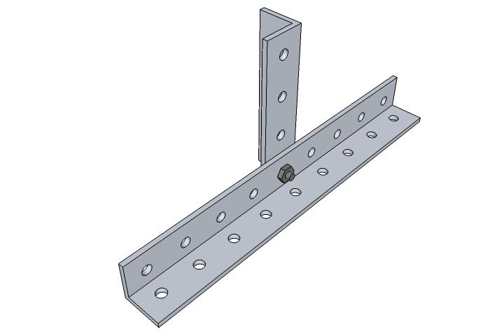
5 005-Lead-nut-assembly Loosen the small screws on the lead nut mount. Align Delrin nut relative to lead nut mount so that the threaded rod is parallel to the angle-18 when looking from the top. Tighten the small screws. Lead nut assembly should now be aligned. Remove angle-18. Threaded rod does not need to be removed. Repeat the process for all lead nuts.

6 006-Motor-preparation Install a pair of nylon screws ( /4") and add two neoprene washers to each screw. Install and fix the jaw coupling onto the motor. Repeat for all motors.

7 007-Flywheel-assembly Assemble flywheel with crank handle, one for each axis.

8 008-X-axis-assembly Attach a pair of angle-6 to one linear bearing using 3/8" screws. Ensure that the angles are roughly orthogonal to the linear bearing and tighten the nuts.

9 009-X-axis-assembly Attach the other linear bearing using 3/8" screws, ensuring that both linear bearings have alignment marker on the same side - see step 21 of linear bearing v2 assembly: Finger tighten the nuts.

10 010-X-axis-assembly Add 1/2" screw and nut pair to the middle of each linear bearing on the opposite side.

11 011-X-rail-assembly Assemble linear rails
12 012-X-rail-assembly Attach linear rails to angle-4s using 3/8" screws and finger tighten the nuts.

13 013-X-rail-assembly Make sure one of the linear rails is square with both angle-4s and tighten the nuts on that rail.

14 014-X-rail-assembly Using a pair of angle-12s, ensure that the rails are parallel and tighten the nuts on the other rail. Do not compress the rails too much - the angle-12s should fall out when you lift the assembly.

15 015-X-rail-assembly Install the motor mount angles using 1/2" screws.

16 016-X-rail-assembly Install the motor mount using 1/2" screws.

17 017-X-rail-assembly Install shaft mounts using 3/8" screws and finger tighten.

18 018-X-axis-assembly Slide the X stage onto the X rail.

19 019-X-axis-assembly Attach angle-6 to the rear of the X stage. Tighten the nut on the same bearing on which you tightened the front angle-6 pair. Let the opposite nut loose.

20 020-X-axis-assembly Stand the axis upright on a flat surface, tightened bearing down. Loosen the pair of nuts holding front angle-6 to the top bearing of the stage. Apply sufficient pressure on the top linear bearing to ensure there is no slack in the rails and gradually tighten the nuts on the top bearing, alternating between front and rear. Once tightened, the stage should glide on the rail. Hold the rail in both hands and try to skew the stage relative to the rail. If you feel or hear slack, repeat the tightening process. If you are unable to remove the slack, go back and verify alignment of the linear bearings.

21 021-X-axis-alignment Lead nut assembly should be attached to Y stage with a pair of 1/8" nylon spacers in between.

22 022-X-axis-alignment Attach the lead nut assembly to Y stage and finger tighten the nuts. Place small screwdriver tip under the screw heads to hold the screws in place.

23 023-X-axis-alignment The next step is to align the lead nut and shaft mounts so that their centers are on the same axis. This is probably the most intricate part of the assembly. This step is very important because misalignment will cause threaded rod to bend and require more torque to turn it, leading to skipped steps. The alignment is performed by adjusting the lead nut sideto-side and the shaft mounts up-down, until desired result is achieved. The success criteria is that you must be able to easily rotate the threaded rod with your fingers once it is constrained by the bearings. Free rotation must be present throughout entire length of stage travel, including extreme positions of the stage. New Delrin lead nuts may be a bit tight and the free rotation may not be achievable until they "break in". In general though, Delrin lead nuts have lower friction and are more forgiving to misalignment, thus they are recommended for the initial builds. With new Delrin lead nuts, simply ensure that turning the threaded rod constrained by the bearings does not feel more difficult than turning unconstrained rod. If the Delrin nuts are too tight (hard to turn with your fingers), it is recommended to run the threaded rod through the nuts back and forth several times, using a power drill.

24 024-X-axis-alignment Put alignment spacers on both ends of the threaded rod near the lead nut, flanges toward each other. Center the stage relative to shaft mounts and turn the threaded rod until the lead nut is in the middle of it. Use cordless/power drill to do this quickly. Loosen the lead nut and position it so that the threaded rod visually passes through the centers of both shaft mounts in the horizontal plane, then carefully tighten the lead nut in this position. This part is tricky as the leadnut may want to turn/move as you tighten it, in the direction of tightening. You can compensate for it by holding the threaded rod slightly off center in the opposite direction. With lead nut tightened, move the stage to extreme positions as misalignment is more visible that way. When alignment spacers are snapped onto the shaft mounts (see motor end shaft mount), they help clearly see whether/where the eccentricity between shaft mount hole and the threaded rod is. Keep in mind that the rod may be very slightly bent, in which case its ends may be a bit off the true center axis. Rotate the rod a couple of turns to see where the true center axis is.

25 025-X-axis-alignment Once the lead nut is tightened, adjust the shaft mount up-down so that the threaded rod passes through its center in the vertical plane. When repositioning the shaft mount, remember to keep it square to the leadscrew - this can be done with an extra angle-1. Tighten the shaft mount nut and not the screw to avoid rotating the shaft mount. Once repositioned, move the stage close to the shaft mount as misalignment is more visible that way. Alignment spacers help clearly see whether/where the eccentricity between shaft mount hole and the leadscrew is. Verify that threaded rod is still centered in the horizontal plane (sideways) - if not, go back to previous step. Repeat the same process with the opposite shaft mount.
 and turning the rod should not be more difficult than turning the unconstrained rod (b).")
26 026-X-axis-alignment Once threaded rod passes through shaft mount centers, install the bearings and test alignment as follows: Add R188 (1/4" ID) bearing to one of the shaft mounts and move the stage until it hits that shaft mount. The threaded rod should easily slide in and out of the bearing (a) and turning the rod should not be more difficult than turning the unconstrained rod (b). If either of the above tests fail, use alignment spacers to identify where the eccentricity is and go back one or two steps to improve alignment. If both tests pass, remove the bearing, move stage to the opposite end of the axis and do the same with the other shaft mount.

27 027-X-axis-alignment Repeat the tests (a) and (b) from the previous step with both shaft mount bearings installed, stage at each of the extreme positions, and threaded rod passing through both bearings. Use cordless/power drill to quickly turn the threaded rod. Generally, if tests are passing for each of the shaft mounts individually, they should pass with both bearings installed. Here are some additional alignment tips: - Look at the threaded rod through the bearing hole with alignment spacer to find eccentricity - Wiggle the threaded rod around its axis in circular motion to find the true center axis and visually compare that with the shaft mount hole Remove alignment spacers when done.

28 028-X-axis-alignment Thread the plastic nut and a steel nut on the motor end of the threaded rod. One side of the plastic nut has a visible indentation - orient it away from the bearing. Test-fit the motor to the motor mount and turn the plastic nut until it is flush with the shaft mount bearing. It is best to leave a small gap (1/16") between the rod and the rubber spider of the coupling. Tighten the steel nut against the plastic nut.

29 029-X-axis-alignment Pull out the threaded rod at the motor end and wrap threaded rod into one turn of electrical tape about 1/4" wide immediately next to the plastic nut. Standard 3/4" wide electrical tape wraps exactly one turn on 1/4-20 threaded rod. Bearing will fit over the tape - that way axis should be quieter.
30 030-X-axis-alignment At the opposite end of the axis, mark the bearing edge on the threaded rod. Push the threaded rod towards the motor and wrap it in one turn of electrical tape about 1/4" wide so that the bearing would fit over the tape. Standard 3/4" wide electrical tape wraps exactly one turn on 1/4-20 threaded rod. Pull the threaded rod away from motor until it's restrained by the nuts on the motor end.

31 031-X-axis-alignment Add the plastic nut to the rod and turn it until flush with the bearing. One side of the plastic nut has a visible indentation - orient it away from the bearing. Do not overtighten the plastic nut - stop as soon as you feel that it's become harder to turn the rod due to compression at the shaft mounts. Thread the steel nut until it stops against the plastic nut. When you tighten the plastic nut against the steel nut, this should relieve the plastic nut pressure on the bearing and the threaded rod should now rotate freely. If there is too much axial slack, carefully tighten two steel nuts against each other, little by little. If you can hear axial slack but do not see it, it's probably ok. At this point it may be good to double check the free rotation at extreme positions of the stage, though with Delrin nuts it shouldn't be necessary.

32 032-X-axis-alignment Install rubber grommets into the mounting holes of the motor mount using a small screwdriver or hex key.

33 033-X-axis-alignment Put the coupling hub onto the threaded rod and install the motor. The plastic screws should be turned with a flat screwdriver so that the grommets don't pop out. Do not tighten the coupling hub on the leadscrew yet.

34 034-X-axis-alignment If necessary, loosen and re-align the motor mount to make threaded rod and motor shaft visibly co-axial. Again, the goal is free rotation of the threaded rod - or as free as it gets in the case of new Delrin nuts. Once aligned, tighten the coupling hub on the leadscrew. The coupling hub should be tightened well as it has the tendency to get loose otherwise. Congratulations, the axis should now be working. Optionally, connect the motor to the stepper driver and verify that everything works.

35 035-X-axis-assembly Add dremel mount to X stage with a pair of screws, 1/8" spacers and nuts. Use a small screwdriver to push the second spacer in the desired position.

36 036-X-axis-assembly Install the flywheel.

37 037-Y-stage-bearing-assembly Connect two linear bearings to angle-9 using 1/8" thick spacers between the bearings and the angle as shown. Note the orientation of the marker, it should be the same on both bearings. Finger tighten the nuts.

38 038-Y-stage-bearing-assembly On a flat surface, (or angle-12) push down on the bearings while tightening the nuts with hex socket. This will ensure the bearings are oriented along the same line. The angle-9 does not have to be parallel to the bearings.

39 039-Y-stage-bearing-assembly Add screw + nut pair to each bearing as shown.

40 040-Y-axis-assembly Assemble the opposite linear bearing. Note the orientation of the markers on the linear bearings and ensure they're all on the same side.

41 041-Y-axis-assembly Attach linear bearings to the table using 1/2" screws, washers and nuts. Finger tighten the nuts.

42 042-Y-rail-assembly Assemble linear rails

43 043-Y-rail-assembly Attach linear rails to angle-4s using 3/8" screws and finger tighten the nuts.

44 044-Y-rail-assembly Make sure one of the linear rails is square with both angle-4s and tighten the nuts on that rail.
45 045-Y-rail-assembly Using a pair of angle-18s, ensure that the rails are parallel and tighten the nuts on the other rail. Do not compress the rails too much - the angle-18s should fall out when you lift the assembly.

46 046-Y-rail-assembly Install the motor mount angles using 1/2" screws.

47 047-Y-rail-assembly Install the motor mount using 1/2" screws.

48 048-Y-rail-assembly Install shaft mounts using 3/8" screws and finger tighten.

49 049-Y-axis-assembly Slide the stage onto the rail and lay the assembly, table down.
50 050-Y-axis-assembly Hold the screw on one of the linear bearings and remove the nut; add angle-6 as shown, replace the nut but do not tighten it - leave wiggle room to attach angle-6 to the opposite linear bearing. In the same manner attach angle-6 to the opposite linear bearing. Repeat the process with the other angle-6 as shown and finger tighten all four nuts. Ensure that the angles are roughly orthogonal to one of the linear bearings (e.g. nearest to you) and tighten the nuts on that bearing. Also tighten the nuts attaching the table to the same linear bearing.
51 051-Y-axis-assembly Loosen the pair of nuts holding angle-6s to the opposite linear bearing of the stage (e.g. farthest from you). Also loosen the nuts attaching the table to the same linear bearing. Apply sufficient pressure on the linear bearings as shown to ensure there is no slack and gradually tighten the nuts on the farthest bearing, alternating between table and angle sides. Once tightened, the stage should glide on the rail. Hold the rail in both hands and try to skew the stage relative to the rail. If you feel or hear slack, repeat the tightening process with the first linear bearing (e.g. nearest to you). If you are unable to remove the slack, go back and verify alignment of the linear bearings.

52 052-Y-axis-assembly Attach angle-1 to angle-6 using 3/8" screw.

53 053-Y-axis-alignment Lead nut assembly should be attached to Y stage with a pair of 1/8" nylon spacers in between.

54 054-Y-axis-alignment Attach the lead nut assembly to Y stage and finger tighten the nuts. Place small screwdriver tip under the screw heads to hold the screws in place.

55 055-Y-axis-alignment The next step is to align the lead nut and shaft mounts so that their centers are on the same axis. This is probably the most intricate part of the assembly. This step is very important because misalignment will cause threaded rod to bend and require more torque to turn it, leading to skipped steps. The alignment is performed by adjusting the lead nut sideto-side and the shaft mounts up-down, until desired result is achieved. The success criteria is that you must be able to easily rotate the threaded rod with your fingers once it is constrained by the bearings. Free rotation must be present throughout entire length of stage travel, including extreme positions of the stage. New Delrin lead nuts may be a bit tight and the free rotation may not be achievable until they "break in". In general though, Delrin lead nuts have lower friction and are more forgiving to misalignment, thus they are recommended for the initial builds. With new Delrin lead nuts, simply ensure that turning the threaded rod constrained by the bearings does not feel more difficult than turning unconstrained rod. If the Delrin nuts are too tight (hard to turn with your fingers), it is recommended to run the threaded rod through the nuts back and forth several times, using a power drill.

56 056-Y-axis-alignment Put alignment spacers on both ends of the threaded rod near the lead nut, flanges toward each other. Center the stage relative to shaft mounts and turn the threaded rod until the lead nut is in the middle of it. Use cordless/power drill to do this quickly. Loosen the lead nut and position it so that the threaded rod visually passes through the centers of both shaft mounts in the horizontal plane, then carefully tighten the lead nut in this position. This part is tricky as the leadnut may want to turn/move as you tighten it, in the direction of tightening. You can compensate for it by holding the threaded rod slightly off center in the opposite direction. With lead nut tightened, move the stage to extreme positions as misalignment is more visible that way. When alignment spacers are snapped onto the shaft mounts (see motor end shaft mount), they help clearly see whether/where the eccentricity between shaft mount hole and the threaded rod is. Keep in mind that the rod may be very slightly bent, in which case its ends may be a bit off the true center axis. Rotate the rod a couple of turns to see where the true center axis is.

57 057-Y-axis-alignment Once the lead nut is tightened, adjust the shaft mount up-down so that the threaded rod passes through its center in the vertical plane. When repositioning the shaft mount, remember to keep it square to the leadscrew - this can be done with an extra angle-1. Tighten the shaft mount nut and not the screw to avoid rotating the shaft mount. Once repositioned, move the stage close to the shaft mount as misalignment is more visible that way. Alignment spacers help clearly see whether/where the eccentricity between shaft mount hole and the leadscrew is. Verify that threaded rod is still centered in the horizontal plane (sideways) - if not, go back to previous step. Repeat the same process with the opposite shaft mount.
 and turning the rod should not be more difficult than turning the unconstrained rod (b).")
58 058-Y-axis-alignment Once threaded rod passes through shaft mount centers, install the bearings and test alignment as follows: Add R188 (1/4" ID) bearing to one of the shaft mounts and move the stage until it hits that shaft mount. The threaded rod should easily slide in and out of the bearing (a) and turning the rod should not be more difficult than turning the unconstrained rod (b). If either of the above tests fail, use alignment spacers to identify where the eccentricity is and go back one or two steps to improve alignment. If both tests pass, remove the bearing, move stage to the opposite end of the axis and do the same with the other shaft mount.

59 059-Y-axis-alignment Repeat the tests (a) and (b) from the previous step with both shaft mount bearings installed, stage at each of the extreme positions, and threaded rod passing through both bearings. Use cordless/power drill to quickly turn the threaded rod. Generally, if tests are passing for each of the shaft mounts individually, they should pass with both bearings installed. Here are some additional alignment tips: - Look at the threaded rod through the bearing hole with alignment spacer to find eccentricity - Wiggle the threaded rod around its axis in circular motion to find the true center axis and visually compare that with the shaft mount hole Remove alignment spacers when done.

60 060-Y-axis-alignment Thread the plastic nut and a steel nut on the motor end of the threaded rod. One side of the plastic nut has a visible indentation - orient it away from the bearing. Test-fit the motor to the motor mount and turn the plastic nut until it is flush with the shaft mount bearing. It is best to leave a small gap (1/16") between the rod and the rubber spider of the coupling. Tighten the steel nut against the plastic nut.

61 061-Y-axis-alignment Pull out the threaded rod at the motor end and wrap threaded rod into one turn of electrical tape about 1/4" wide immediately next to the plastic nut. Standard 3/4" wide electrical tape wraps exactly one turn on 1/4-20 threaded rod. Bearing will fit over the tape - that way axis should be quieter.
62 062-Y-axis-alignment At the opposite end of the axis, mark the bearing edge on the threaded rod. Push the threaded rod towards the motor and wrap it in one turn of electrical tape about 1/4" wide so that the bearing would fit over the tape. Standard 3/4" wide electrical tape wraps exactly one turn on 1/4-20 threaded rod. Pull the threaded rod away from motor until it's restrained by the nuts on the motor end.
63 063-Y-axis-alignment Add the plastic nut to the rod and turn it until flush with the bearing. One side of the plastic nut has a visible indentation - orient it away from the bearing. Do not overtighten the plastic nut - stop as soon as you feel that it's become harder to turn the rod due to compression at the shaft mounts. Thread the steel nut until it stops against the plastic nut. When you tighten the plastic nut against the steel nut, this should relieve the plastic nut pressure on the bearing and the threaded rod should now rotate freely. If there is too much axial slack, carefully tighten two steel nuts against each other, little by little. If you can hear axial slack but do not see it, it's probably ok. At this point it may be good to double check the free rotation at extreme positions of the stage, though with Delrin nuts it shouldn't be necessary.

64 064-Y-axis-alignment Install rubber grommets into the mounting holes of the motor mount using a small screwdriver or hex key.

65 065-Y-axis-alignment Put the coupling hub onto the threaded rod and install the motor. The plastic screws should be turned with a flat screwdriver so that the grommets don't pop out. Do not tighten the coupling hub on the leadscrew yet.

66 066-Y-axis-alignment If necessary, loosen and re-align the motor mount to make threaded rod and motor shaft visibly co-axial. Again, the goal is free rotation of the threaded rod - or as free as it gets in the case of new Delrin nuts. Once aligned, tighten the coupling hub on the leadscrew. The coupling hub should be tightened well as it has the tendency to get loose otherwise. Congratulations, the axis should now be working. Optionally, connect the motor to the stepper driver and verify that everything works.

67 067-Y-axis-assembly Install the flywheel.

68 068-Z-stage-bearing-assembly Attach sliding-element-2.5 to angle-4 and finger tighten the nuts.

69 069-Z-stage-bearing-assembly Insert lead nut assembly into the sliding element, add washers and nuts, finger tighten.

70 070-Z-stage-bearing-assembly Remove the leadscrew and attach sliding-element-1 to angle-4 as shown.

71 071-Z-stage-bearing-assembly Place assembly on a flat surface and push on top of the sliding elements while tightening the nuts to ensure that sliding elements are on the same axis.

72 072-Z-stage-bearing-assembly Add 1 inch long screws and nuts to the bottom of the sliding elements. Insert the leadscrew back into the slidingelement-2.5.

73 073-Z-half-axis-assembly Assemble rail structure.
74 074-Z-half-axis-assembly Add shaft mount and motor mount.

75 075-Z-half-axis-assembly Slide Z stage bearing on the rail and add angle-4 at the end of the rail.
76 076-Z-half-axis-assembly Assemble helper stand.

77 077-Z-half-axis-assembly Attach helper stand to angle-4.

78 078-Z-half-axis-assembly The next step is to align the lead nut and the shaft mount so that their centers are on the same axis. This is very important because misalignment will cause leadscrew to bend and require more torque to turn it, leading to skipped steps, ruined cutting jobs and broken tools. The alignment is performed in several iterations by loosening, repositioning and tightening the lead nut (up-down) and the shaft mount (side-to-side) until desired result is achieved. The general guideline is that you must be able to easily rotate the threaded rod with your fingers once it is constrained by the bearings.

79 079-Z-half-axis-assembly Alignment can be inspected visually by moving the stage with the lead nut as close as possible to the shaft mount. The leadscrew should pass through the center of the shaft mount hole. Rotate the threaded rod a couple of turns to ensure this is the case at every angle as the rod may be very slightly bent.

80 080-Z-half-axis-assembly When threaded rod appears centered, put steel and plastic nuts (1/4-20) on the rod. One side of the plastic nut has a visible indentation - orient it away from the bearing. Snap R188 bearing between the small screws of the shaft mount. Move Z stage bearing as close as possible to the shaft mount and verify alignment again: threaded rod should easily slide in and out of the bearing, and with the plastic nut flush against the bearing, you should be able to freely turn the rod with your fingers. Go back two steps if either of the above is not the case.

81 081-Z-half-axis-assembly Test-fit the motor to the motor mount and position the threaded rod so there is a small gap (1/16") between the rod and the rubber spider of the coupling. Hold the threaded rod in this position and turn the plastic nut until it is flush with the shaft mount bearing.

82 082-Z-half-axis-assembly Turn and tighten the steel nut against the plastic nut to fix the position of the plastic nut. Do not overtighten or you may strip the threads on the plastic nut. Generally, a quarter of a turn should be sufficient.

83 083-Z-half-axis-assembly Test-fit the motor again, and move the coupling hub onto the coupling spider to radially restrain the threaded rod. Do not tighten the coupling hub yet. Check for free rotation again, slightly pulling the threaded rod away from the axis. If adding the motor makes turning the rod difficult, go back to the alignment process.

84 084-Z-half-axis-assembly Install the thrust bearing. Add plastic nut and steel nut and tighten them so that the leadscrew is able to rotate freely. One side of the plastic nut has a visible indentation - orient it away from the bearing. There should be just enough axial slack - not visible but you should be able to hear it if you move the threaded rod back and forth along its axis.

85 085-Z-half-axis-assembly Manually verify free rotation of the threaded rod throughout the stage travel. It's important that there are no spots on the rod where you need to apply extra torque to turn it (see prep phase).
86 086-Z-half-axis-assembly Remove helper stand and attach angle-2 to the end of the rail.
, and there is")
87 087-Z-axis-assembly Assemble and align another half of the Z axis. The other half is a mirror copy of the first half, except that it uses angle-4 and -3 in the rail assembly (instead of angle-6 and -6), and there is no motor mount. The alignment process to follow is the same as for the first half.

88 088-Z-axis-assembly Assemble the top bar from two angle-9s and angle-1.

89 089-Z-axis-assembly Build a helper assembly that will ensure that two halves of Z axis are parallel.

90 090-Z-axis-assembly Attach the top bar assembly to both halves of Z axis as shown. Tighten the left side but not the right side. Move both linear bearings to the top of the axis.
91 091-Z-axis-assembly The pulleys should be secured with 1/4-20 nuts because the current version of the pulleys has a poor set screw grip on the threaded rod. Add a pair of 1/4-20 nuts to the threaded rods as shown and wrap each rod in ~7/8" length of electrical tape above the nuts. Standard 3/4" wide electrical tape wraps exactly one turn on 1/4-20 threaded rod.

92 092-Z-axis-assembly Take XL-240 belt and pair of pulleys, slide the pulleys with the belt onto the threaded rod ends. Push the pulleys all the way down onto the tape, making sure the tape doesn't crumple. Add top 1/4-20 nuts but do not tighten them yet.

93 093-Z-axis-assembly Loosen the nut connecting the right angle-2 to angle-18 in the helper assembly and attach the helper assembly to each half of Z axis as shown. Move the right side to adjust the belt tension. The rods should not bend under tension but there also should not be a slop in the belt. You should still be able to easily rotate the threaded rods by pulling at the belt. Once the belt tension feels right, tighten the right side - helper assembly first and then the top bar assembly. Tighten the pulleys on the threaded rods with the hex nuts.
 and re-attach it at the other end of the axis as shown.")
94 094-Z-axis-assembly Disconnect the helper assembly (keep angle-2s attached and tightened to angle-18) and re-attach it at the other end of the axis as shown.

95 095-Z-axis-assembly Manually verify easy rotation of the belt-coupled threaded rods throughout the travel of the bearings, by pulling the belt. It's important that there are no spots on the rod where you need to apply extra torque to turn it.

96 096-Z-axis-assembly Install rubber grommets into the mounting holes of the motor mount.

97 097-Z-axis-assembly Install the motor. The plastic screws should be turned with a flat screwdriver so that the grommets don't pop out. Do not tighten the coupling hub on the threaded rod yet.

98 098-Z-axis-assembly Install the flywheel.

99 099-Base-assembly Assemble base rear.

100 100-Base-assembly Assemble base front.

101 101-mini-CNC-assembly Attach pair of angle-9s to pair of angle-18s as shown, using 3/8" screws.
 to the lower end of Z")
102 102-mini-CNC-assembly Attach resulting base beams at 6th hole (of angle-18s) to the lower end of Z axis.

103 103-mini-CNC-assembly Stand Z axis with base beams on top of front and rear base assemblies, attach at each corner and tighten. Outermost angle-2s of base rear may need to be repositioned.

104 104-mini-CNC-assembly Remove helper assembly.

105 105-mini-CNC-assembly Remove hex nuts from the long screws on Z stage bearings and add a pair of 1/4-20 square nuts to each screw.

106 106-mini-CNC-assembly Install X axis on the long screws and finger tighten the nuts.

107 107-mini-CNC-assembly Install Y axis and tighten the nuts.

108 108-mini-CNC-assembly Center the Y stage and put a pair of sliding elements on the opposite ends of the table. Loosen the nuts connecting X axis to Z stage bearings and lower X axis until its bottom rail touches both sliding elements. Carefully tighten X axis nuts in this position and verify that the pulley can be easily turned. You will feel more resistance when raising X axis (vs lowering it), but the torque needed to turn the pulley should be the nearly same at every angle. If you feel significant variation in torque through all or part of Z travel length, the belt may be overtightened. It's also possible that threaded rod may be bent or have some defects, but this would have been mostly ruled out by free rotation tests in Z half-axis assembly. Tighten the motor coupling hub on Z axis (threaded rod side).

109 109-mini-CNC-assembly Install angle-18 supports and tighten.
110
GlideRite Retractable Cover System For HotSpring & Tiger River Spas (except Classic & pre-2000 Landmark Spas)
") List of Contents Quantity Description 12 #10 x 1 ½ Flat Head Phillips Screw (see pg. 2) 2 #10 x ½ Pan Head Phillips Screw (see pg. 2) 8 ¼ x 2 ½ Lag Bolt (see pg. 2) 7 ¼ 20 x 5 / 8 Hex Head Bolt (see pg.
List of Contents Quantity Description 12 #10 x 1 ½ Flat Head Phillips Screw (see pg. 2) 2 #10 x ½ Pan Head Phillips Screw (see pg. 2) 8 ¼ x 2 ½ Lag Bolt (see pg. 2) 7 ¼ 20 x 5 / 8 Hex Head Bolt (see pg.
ABM International, Inc. Navigator Assembly Manual
 ABM International, Inc. 1 1.0: Parts List Tablet (Qty. 1) Tablet mount (Qty. 1) NOTE: Mount may appear and operate different then image below Control Box (Qty. 1) Motor Power Supply (Qty. 1) 2 X-axis motor
GlideRite Retractable Cover System For Hot Spot Spas (SE & SLX only)
") List of Contents Quantity Description 12 #10 x 1 ½ Flat Head Phillips Screw (see pg. 2) 2 #10 x ½ Pan Head Phillips Screw (see pg. 2) 8 ¼ x 2 ½ Lag Bolt (see pg. 2) 7 ¼ 20 x 5 / 8 Hex Head Bolt (see pg.
List of Contents Quantity Description 12 #10 x 1 ½ Flat Head Phillips Screw (see pg. 2) 2 #10 x ½ Pan Head Phillips Screw (see pg. 2) 8 ¼ x 2 ½ Lag Bolt (see pg. 2) 7 ¼ 20 x 5 / 8 Hex Head Bolt (see pg.
re3d Assembling Gigabot: "Flatpack"
 re3d Assembling Gigabot: "Flatpack" Your Gigabot was assembled, calibrated, tested, and taken apart for shipping purposes. All you need to do is reassemble it, and you're ready to go! Written By: Chris
Removing and Replacing the Y-truck
 Service Documentation Removing and Replacing the Y-truck To remove and replace the Y-truck you will need the following tools: 4mm Allen wrench 12mm stamped flat wrench #2 Phillips screwdriver (magnetic
Lumber Smith. Assembly Manual. If you are having problems assembling the saw and need assistance, please contact us at:
 Lumber Smith Assembly Manual If you are having problems assembling the saw and need assistance, please contact us at: 804-577-7398 info@lumbersmith.com 1 Step 1 Safety Carefully read the Owners Manual.
Elimination of Elevator Bounce
 For the Agilent Archon Autosampler Rework Instructions CAUTION This kit is intended for use by Agilent Service personnel only. Elevator Removal 1 Open top cover. 2 Open front lower door. 3 Remove vial
V4 Premium Kit. Prusa i3 Build Guide
 V4 Premium Kit Prusa i3 Build Guide Hi! Congratulations on your purchase of the DIYElectronics.co.za Prusa I3 kit, the best South African 3D Printer Kit! Hopefully this should serve as complete guide to
This manual will aid in the assembly of the FireBall V90 and FireBall X90. The assembly of both machines will be identical, unless specified.
 This manual will aid in the assembly of the FireBall V90 and FireBall X90. The assembly of both machines will be identical, unless specified. Step #1 Lay all parts out to verify quantities. (2) 2 x 25-1/4
Electric Skein Winder
 Electric Skein Winder Assembly and Use Package Contents 1 - Triangular Body (w/ motor) 1 - Cross Arm 1 - Left Foot (w/ yarn guide) 1 - Right Foot 1 - Adjustable Finger (w/ yarn clip) 3 - Adjustable Fingers
Metroboard Pulley Replacement Procedure
 Metroboard Pulley Replacement Procedure 1) Remove the two transmission cover screws (1/8 allen driver). Then remove the transmission cover. Note there is a split lock washer and flat washer as well, so
C70 Window Roller Repair Taken from: Heres the problem:
 C70 Window Roller Repair Taken from: http://www.volvospeed.com/vs_forum/topic/115086-how-to-c70-window-rollers-permanent-fix/ Heres the problem: This happened to two separate window assemblys on my c70
4. Z-axis assembly. 4. Z-axis assembly. Written By: Josef Prusa manual.prusa3d.com Page 1 of 18
 4. Z-axis assembly Written By: Josef Prusa 2017 manual.prusa3d.com Page 1 of 18 Step 1 Get the necessary tools 13/17mm spanners 3.6mm flathead screwdriver Needle-nose pliers 2.5 and 1.5mm Allen key Step
Brother Industries, Ltd. Nagoya, Japan
 4. 2001. This service manual has been compiled for explaining repair procedures of the MODEL XL-6562, XL6452, XR- 46. This was produced based on up-to-date product specifications at the time of issue,
Removing the Z-Axis lead screw
 Page 1 of 8 TITLE: Sabre Z-Axis Lead Screw Replacement Procedure Gerber FastFact #: 5048 Supplied by: Gerber Hardware Support Last Modified: June 14, 2007 Summary: Tools used: The following procedure explains
RTI TECHNOLOGIES, INC.
 RTI TECHNOLOGIES, INC. BRC500 & BRC550 Arbor/Spindle Mechanism Adjustment & Service Technical Instructions The arbor/spindle mechanism of the BRC500/550 is designed to be robust for long life. Occasionally
Referencing 0,0 position
 Page 1 of 11 TITLE: SABRE X-Axis Lead Screw Replacement Procedure Gerber FastFact #: 2013 Supplied by: Gerber Hardware Support Last Modified: March 1, 2011 Summary: The following procedure explains how
Flexshaft Assembly. Flexshaft Support Tube. Clear Front Cover FIGURE 1: EXTERIOR VIEW OF THE FLEXSHAFT AND HEAD COVERS
 Adjusting the Head Pressure Checking the head pressure and adjusting the vertical guide rods is part of the machine set-up process. The head pressure should also be checked periodically during routine
INSTALLING YOUR NEW SPRING LIFT ARM KIT
 INSTALLING YOUR NEW SPRING LIFT ARM KIT 1. Measure the distance that the roof is to be raised. [If your lift system is completely non-functional, you will need to calculate or estimate this distance as
Shapeoko XXL Assembly Guide
 Shapeoko XXL Assembly Guide 04/27/2016 XXL Packing LIst Item Qty Description Y-Carriage (left) 1 Y-Carriage (right) 1 X/Z Assembly 1 40 Rail 3 1 rail has mounting holes for controller Wasteboard Half 2
LIGHT BEAM ANTENNA MaxRange Antenna Series Assembly Instructions MaxRange Plus Digital / High Definition Television Antennas
 LIGHT BEAM ANTENNA MaxRange Antenna Series Assembly Instructions MaxRange Plus Digital / High Definition Television Antennas Assembly Instructions 1 MaxRange Plus Antenna These instructions will lead you
CRP700 Benchtop Basic CNC Machine Assembly Instructions. Updated 10/24/2014 SHEET 1 of 24
 CRP700 Benchtop Basic CNC Machine Assembly Instructions Updated 0//0 SHEET of NOTE: This piece of extrusion is mounted wide side up Quick Tip: Lay extrusion on table as shown for easy assembly BASE ASSEMBLY:.
Installation and Assembly - Universal Articulating Swivel Double-Arm for 42" - 60" Plasma Screens
 Installation and Assembly - Universal Articulating Swivel Double-Arm for 42" - 60" Plasma Screens Models: PLAV 70-UNL, PLAV 70-UNL-S PLAV 70-UNLP, PLAV 70-UNLP-S R This product is UL Listed. It must be
AUTOMATIC ADVANCE MANUAL
 AUTOMATIC ADVANCE MANUAL AVL Looms, Inc. 3851 Morrow Lane, Suite #9 Chico, CA 95928-8305 530 893-4915 530 893-1372 fax # info@avlusa.com www.avlusa.com Copyright 2009 TABLE OF CONTENTS Page # I. Parts.........................
MantelMount. TM1A Installation Instructions IMPORTANT SAFETY INSTRUCTIONS - SAVE THESE INSTRUCTIONS
 MantelMount TMA Installation Instructions IMPORTANT SAFETY INSTRUCTIONS - SAVE THESE INSTRUCTIONS TM Thank you for choosing the MantelMount television wall mount. Please read this entire manual before
Assembly Guide for Printrbot - Simple Maker s Edition 1405
 Assembly Guide for Printrbot - Simple Maker s Edition 1405 Last update: March 2016 Please Note: be careful on the steps that are underlined 1 Contents Tools Needed:... 3 First step: Check components and
Castle Frame Assembly Table AT-8. Diagnostics Manual. Castle, Inc. Petaluma, CA
 Castle Frame Assembly Table AT-8 Diagnostics Manual Castle, Inc. Petaluma, CA 800-282-8338 Solutions Index Adjusting the Tabletop.. 8.01 Adjusting the Fence... 8.02 Aligning the Arm... 8.10 Adjusting Bracket..
User Instructions Multiline Otter Scoreboard Caddy Assembly
 List of parts: User Instructions Multiline Otter Scoreboard Caddy Assembly Single Caddy Double Caddy 1 1 Base assembly with attached wheels 2 4 1 1 2 4 4 8 10 20 12 Uprights (60 or 74 aluminum extrusion)
Deck Mount Installation with Bench
 Deck Mount Installation with Bench 1. Mark track with square. 2. Cut tracks with saw. 3. Drill ¼ hole (if needed.) 4. Countersink track. 5. Countersink all track 6. File all track ends. ends. 7. Lay out
TRUE TECHNICAL SERVICE MANUAL - ALL MODELS. DOORS/DRAWERS/LIDS
 DOORS/DRAWERS/LIDS 55 56 NOTES DOORS/DRAWERS/LIDS Springs 97 TORSION SPRING REPLACEMENT GDM RADIUS FRONT - SWING DOOR INSTALLATION INSTRUCTIONS Tools Required (2) - 1 8" drift Punch (forged) Needle-Nose
Installation and Assembly - Universal Articulating Swivel Double-Arm for 42" - 60" Plasma Screens
 Installation and Assembly - Universal Articulating Swivel Double-Arm for 42" - 60" Plasma Screens Models: PLAV 70-UNL, PLAV 70-UNL-S PLAV 70-UNLP, PLAV 70-UNLP-S R This product is UL Listed. It must be
400A 40113V, 401A 40120V, & 401AL 40120VL ALUMINUM VERTICAL 4000 LB LIFT INCLUDES SCREW LEG ASSEMBLY INSTRUCTIONS
 12/11/07 PAGE 1 OF 12 400A 40113V, 401A 40120V, & 401AL 40120VL ALUMINUM VERTICAL 4000 LB LIFT INCLUDES SCREW LEG ASSEMBLY INSTRUCTIONS Thank you for purchasing our product! *Please read these instructions
SatNOGS. SatNOGS Rotator v3 Mechanical Assembly. This is the assembly guide for the third version of the SatNOGS Rotator.
 SatNOGS SatNOGS Rotator v3 Mechanical Assembly This is the assembly guide for the third version of the SatNOGS Rotator. Written By: Pierros Papadeas 2017 satnogs.dozuki.com Page 1 of 19 INTRODUCTION Notes:
MM540 Installation Instructions IMPORTANT SAFETY INSTRUCTIONS - SAVE THESE INSTRUCTIONS
 MM50 Installation Instructions IMPORTANT SAFETY INSTRUCTIONS - SAVE THESE INSTRUCTIONS Please read this entire manual before you begin. Do not unpack any contents until you verify all requirements on PAGE.
Kai Installation Instructions
 Kai Installation Instructions Before Beginning Installation Read through the entire instruction thoroughly A minimum of 2 people are required for this assembly These instructions reflect typical assemblies;
1.75mm Direct Titan Assembly
 1.75mm Direct Titan Assembly Learn how to assemble your Titan for use with 1.75mm filament in a direct configuration. Written By: Gabe S. 2018 e3d-online.dozuki.com/ Page 1 of 20 TOOLS: Hex Wrench, 1.5mm
The Useless Machine. DIY Soldering Edition. Instruction Guide v0004
 The Useless Machine DIY Soldering Edition Instruction Guide v0004 TM For the best outcome, follow each step in order. We recommend reading this guide entirely before you get started. Tools required: Soldering
HQ Precision-Glide Track Upgrade 2 Extension Kit for HQ Studio Frame Part# QF09750
 HQ Precision-Glide Track Upgrade 2 Extension Kit for HQ Studio Frame Part# QF09750 Important Note: Upgrading the track system on the HQ Studio Frame requires the use of this 2 Extension Kit (Part #QF09750),
MODEL SK61732 COMPRESSOR SERVICE KIT
 MODEL SK61732 COMPRESSOR SERVICE KIT For use on 607 and 617 Model Compressors with.32 Stroke WARNING: Unplug the compressor before beginning disassembly. CAUTION: Improper assembly or use of damaged parts
ABM International, Inc.
 ABM International, Inc. Lightning Stitch required 1 1.0: Parts List head and motor assembly (Qty. 1) Reel stand (Qty. 1) Needle bar frame clamp (Qty. 1) Motor drive (Qty. 1) 2 Cable harness with bracket
Rudders Removal and Stuffing Box Packing by Brian Barton May 31, 2013
 Rudders Removal and Stuffing Box Packing by Brian Barton May 31, 2013 Last year both rudders on my 38 Commander were leaking a little less than a water fall. An adjustment worked on the starboard side.
TRAILMATE METEOR ASSEMBLY MANUAL
 TRAILMATE METEOR ASSEMBLY MANUAL The Trailmate Meteor recumbent has been designed for easy assembly. This means more time to enjoy the smooth ride with single speed, 3 speed coaster brake and 21 speed
This instruction manual is an in-depth look and explanation of how to assemble and install the Murphy Bed properly and efficiently.
 This instruction manual is an in-depth look and explanation of how to assemble and install the Murphy Bed properly and efficiently. Don t be put off by the size of the instruction manual as the large diagrams
RH-412 STEEL DOORS INSTALLATION INSTRUCTIONS
 RH-412 STEEL DOORS INSTALLATION INSTRUCTIONS By following the steps outlined below, the assembly, installation and adjustment of the steel doors, will be a simple process. Let s start with the Driver Side.
3400 to 3440 Scarfing Sled Owners Manual Please Read Carefully!
 3400 to 3440 Scarfing Sled Owners Manual Please Read Carefully! Parts List: Please identify and verify that you have all of the hardware shown. Please refer to photos in the instructions for the parts
CRP700 Benchtop Basic CNC Machine Assembly Instructions. Updated 9/11/2014 SHEET 1 of 25
 CRP700 Benchtop Basic CNC Machine Assembly Instructions Updated 9//0 SHEET of NOTE: This piece of extrusion is mounted wide side up Quick Tip: Lay extrusion on table as shown for easy assembly BASE ASSEMBLY:.
MM340 Installation Instructions IMPORTANT SAFETY INSTRUCTIONS - SAVE THESE INSTRUCTIONS
 MM30 Installation Instructions IMPORTANT SAFETY INSTRUCTIONS - SAVE THESE INSTRUCTIONS Please read this entire manual before you begin. Do not unpack any contents until you verify all requirements on PAGE.
Replacing the Reciprocator on the SWF Compact Series Machine (601C and 1201C)
") Follow the instructions below to replace the reciprocator in the SWF Compact series machines. The tools required can be found in the tool kit that came with the machine. Preparation 1. First, place the
Follow the instructions below to replace the reciprocator in the SWF Compact series machines. The tools required can be found in the tool kit that came with the machine. Preparation 1. First, place the
INSTALLATION INSTRUCTIONS RH 412 STEEL DOORS
 By following the steps outlined below, the assembly, installation and adjustment of the steel doors, will be a simple process. Let s start with the Driver Side. Note: Having the hood open makes the job
MM750 Installation Instructions
 MM750 Installation Instructions IMPORTANT SAFETY INSTRUCTIONS - SAVE THESE INSTRUCTIONS Please read this entire manual before you begin. Do not unpack any contents until you verify all requirements on
INSPECTION AND CORRECTION OF BELLHOUSING TO CRANKSHAFT ALIGNMENT
 INSPECTION AND CORRECTION OF BELLHOUSING TO CRANKSHAFT ALIGNMENT BACKGROUND Proper alignment of the transmission input shaft to the crankshaft centerline is required in order to achieve the best results
Clearview Railing System Installation Instructions
 Clearview Railing System Installation Instructions Disclaimer: AGS Stainless, Inc. has its Clearview Railing Systems designed by a professional engineer to meet the requirements of the latest national
Technicians of Terror. This is the air valve we make to use with our air
 These are pictures of our scissor prop. Technicians of Terror http://www.halloweenfear.com/scissorprop.html props. This is the air valve we make to use with our air This pictures the duel door closer cylinders
Installing CNC Stepper Motor Mounts On A Sherline Mill
 Installing CNC Stepper Motor Mounts On A Sherline Mill P/N 6700 (6710 Metric) 5000/5100/5400/5410 Mills P/N 6705 (6715 Metric) 2000/2010 Mills USING THE TEMPLATE BLOCKS TO LOCATE NEW MOUNTING HOLES FOR
M2 Assembly. M2 Sub-Assemblies mm Belt Sub-Assembly mm Belt Sub-Assembly Spider Sub-Assembly... 4
 M2 Assembly Table of Contents M2 Sub-Assemblies... 3 630mm Belt Sub-Assembly... 3 702mm Belt Sub-Assembly... 3 Spider Sub-Assembly... 4 Idler Bolt Sub-Assembly... 8 Y Motor Sub-Assembly... 9 X Motor Sub-Assembly...
Tuff Tread. 502 W. Montgomery STE 120 Willis, TX PH: (800) FAX: (888)
 FAX: (888)") Motor Brush Holder Assembly Installation Instructions Never use a sanding stone or comm stone on the commutator of a Noramco Fitness Treadmill motor. The commutator of a motor that has been properly broken
Motor Brush Holder Assembly Installation Instructions Never use a sanding stone or comm stone on the commutator of a Noramco Fitness Treadmill motor. The commutator of a motor that has been properly broken
INSTALLATION INSTRUCTIONS SIDE BAR FORD ESCAPE & MAZDA TRIBUTE PART #
 INSTALLATION INSTRUCTIONS SIDE BAR 2008-2010 FORD ESCAPE & MAZDA TRIBUTE PART # 50136 50137 PARTS LIST: 1 Driver/Left Sidebar 2 10-1.50mm x 35mm Bolt Plate 1 Passenger/Right Sidebar 2 10-1.50mm x 30mm
FLIP TARP SINGLE & DOUBLE UNDERBODY TRAILERS
 1-800-248-7717 1002 N. 15th Street, Middlesboro, KY 40965 FLIP TARP SINGLE & DOUBLE UNDERBODY TRAILERS INSTALLATION INSTRUCTIONS Congratulations on your purchase of a Mountain Flip Tarp Trailer system.
3D PRINTER. Pack 11. Anything you can imagine, you can make! 3D technology is now available for you at home! BUILD YOUR OWN
 BUILD YOUR OWN Pack 11 Anything you can imagine, you can make! 3D PRINTER Compatible with Windows 7 & 8 Mac OS X 3D technology is now available for you at home! BUILD YOUR OWN 3D PRINTER CONTENTS PACK
OPERATIONAL MANUAL V1.0. Removing/Replacing Blades
 OPERATIONAL MANUAL V1.0 BLUEROCK WS-212 Wire Stripper Removing/Replacing Blades CAUTION!! IMPORTANT!! DANGER!! WARNING!! DISCONNECT MACHINE FROM POWER BEFORE PROCEEDING!! Estimated Completion Time: 90
Adjusting Backlash on Sherline handwheels
 WEAR YOUR SAFETY GLASSES FORESIGHT IS BETTER THAN NO SIGHT READ INSTRUCTIONS BEFORE OPERATING Adjusting Backlash on Sherline handwheels What Is Backlash? Backlash is the amount the handwheel can turn before
INSTALLATION AND CARE INSTRUCTIONS
 INSTALLATION AND CARE INSTRUCTIONS Skylight Manually Operated Honeycomb Shades 20 C8-10-1806 2/15 1 INTRODUCTION Thank you for purchasing our product. Your new shade has been custom built for you from
Installing the Partridge RA Extension on Losmandy G11
 Installing the Partridge RA Extension on Losmandy G11 Michael Herman July 20, 2015 Tools: 3/16 inch hex key (allen wrench) [If desired for DEC indicator ring friction improvement: flat screwdriver, and
N. 15th Street, Middlesboro, KY FLIP TARP DUMP BODY INSTALLATION INSTRUCTIONS
 1-800-248-7717 1002 N. 15th Street, Middlesboro, KY 40965 FLIP TARP DUMP BODY INSTALLATION INSTRUCTIONS Congratulations on your purchase of a Mountain Flip Tarp Dump Body tarping system. With tarping systems
BABY WOLF LOOM. Assembly Instructions for Knocked-Down Looms
 BABY WOLF LOOM Assembly Instructions for Knocked-Down Looms BEFORE YOU BEGIN Please read through the directions before beginning to assemble your loom. Unpack the loom parts carefully. Do not throw away
MODEL H " BYRD SHELIX CUTTERHEAD INSTRUCTIONS
 MODEL H9291 12" BYRD SHELIX CUTTERHEAD INSTRUCTIONS The Model H9291 12" Byrd Shelix cutterhead is designed to replace the straight-knife cutterhead on the Grizzly jointer Model G0609. The total procedure
FM2113PC/FM2114PC SBC Top Mount Alt, w/ A/C & Power Steering
 10) At this time assemble the power steering bracket and pump assembly from the instructions provided with the power steering bracket beginning at step 7. Return to step 10 on this sheet when complete.
FM2113PC/FM2114PC SBC Top Mount Alt, w/ A/C & Power Steering
 10) At this time assemble the power steering bracket and pump assembly from the instructions provided with the power steering bracket beginning at step 7. Return to step 10 on this sheet when complete.
Installation Instructions for FC2 & FC15 Forward Controls for the Super Magna
 Installation Instructions for FC2 & FC15 Forward Controls for the Super Magna It is highly recommended that you use a thread lock compound such as Loctite brand on all threads to keep them from vibrating
15MM LINEAR MOTION SYSTEM
 222fg 15MM LINEAR MOTION SYSTEM September 20, 2017 15mm Linear Motion System Copyright 2017 REV Robotics, LLC 1 TABLE OF CONTENTS 1 INTRODUCTION... 3 2 ASSEMBLY INSTRUCTIONS... 4 3 How to drive Linear
 For Wallbed models: KING SIZE INSTRUCTION BOOKLET #C1 Watch step by step installation instructions at: https://www.wallbedsbywilding.com/wallbed-installation-studio-series/ WARNING! ALL MURPHY/WALLBED
TIRE RACK INSTALLATION INSTRUCTIONS Dodge Sprinter
 Aluminess Products Inc 9402 Wheatlands Ct. #A Santee, CA 92071 619-449-9930 TIRE RACK INSTALLATION INSTRUCTIONS 07-11 Dodge Sprinter Please read before beginning Stainless steel hardware may bind together
Assembly Instructions: Bencher Skylark
 Assembly Instructions: Bencher Skylark Tools Required: Pop Rivet Tool Tape Measure Hex Wrenches Screwdriver Several Disposable Rags Two Saw Horses Several boxes or bowls to hold fasteners and small parts
Removing outter components
 Y Axis Motor Replacement Replacing the Y axis motor is a process that requires the individual to be somewhat mechanically inclined and can follow detailed instructions. If any of the following steps are
Installing CNC Stepper Motor Mounts On A Sherline Lathe
 Installing CNC Stepper Motor Mounts On A Sherline Lathe P/N 6720 (6725 Metric) 4000/4100/4500/4600 Lathes P/N 6730 (6735 Metric) 4400/4410 Lathe USING THE TEMPLATE BLOCKS TO LOCATE NEW MOUNTING HOLES FOR
Installation Instructions - Model V4JSD 1
 Installation Instructions - Model V4JSD 1 Support Assemblies: Parts list: (Note see enclosed cut sheet for quantities and dimensional information) A vertical structural member (1 ½ x 1 ½ modular frame)
ORTOP Modular Robot v3.0 Arm Assembly
 Base Plate Assembly Parts Needed: Arm Assembly BAG 1 2 Socket Head Cap Screw, 1-1/4" 2 Socket Head Cap Screw, 1/2" 2 Button Head Cap Screw, 3/8" 6 Nuts 1 Gear Hub Spacer 1 Flat Building Plate 1 Single
Printrbot Simple (Model 1403) Rev F Printrboard
 Rev F Printrboard") Printrbot Simple (Model 1403) Rev F Printrboard Printrbot Simple is currently shipping with the Rev F Printrboard. Check which rev Printrboard your Simple kit includes and use the corresponding instructions.
Printrbot Simple (Model 1403) Rev F Printrboard Printrbot Simple is currently shipping with the Rev F Printrboard. Check which rev Printrboard your Simple kit includes and use the corresponding instructions.
RAMPAGE P R O D U C T S. INSTALLATION INSTRUCTIONS BRONCO ZIPPER FASTRACK TOP PART #984xx BRONCO TOOLS REQUIRED
 RAMPAGE P R O D U C T S 84 (+/- 1/4 ) INSTALLATION INSTRUCTIONS BRONCO ZIPPER FASTRACK TOP PART #984xx BRONCO 1966-1977 TOOLS REQUIRED 3/8 WRENCH 7/16 WRENCH ½ WRENCH #2 PHILLIPS SCREWDRIVER 1/8 DRILL
Nancy s Knit Knacks LLC 4 Yard Option Upgrade Kit Assembly Instructions and User Manual
 Nancy s Knit Knacks LLC 4 Yard Option Upgrade Kit Assembly Instructions and User Manual Thank you for purchasing our 4 Yard Option (4YO) Upgrade Kit. To install this upgrade you are simply going to assemble
STEINBERGER TRANSTREM (TYPE 2) TECHNICAL DOCUMENT
 TECHNICAL DOCUMENT") STEINBERGER TRANSTREM (TYPE 2) TECHNICAL DOCUMENT These instructions apply to newer style TransTrems only (non-threaded ball type or modified threaded ball type). For purposes of discussion, these TransTrems
STEINBERGER TRANSTREM (TYPE 2) TECHNICAL DOCUMENT These instructions apply to newer style TransTrems only (non-threaded ball type or modified threaded ball type). For purposes of discussion, these TransTrems
Replacing the Reciprocator on an SWF Multi-head.
 Replacing the Reciprocator on an SWF Multi-head. Follow the instructions below to replace the reciprocator in the SWF multi-head machines. The tools required are found in the tool kit that came with the
MODEL T " SPIRAL CUTTERHEAD INSTALLATION INSTRUCTIONS
 MODEL T27449 8" SPIRAL CUTTERHEAD INSTALLATION INSTRUCTIONS The Model T27449 indexable insert spiral cutterhead is designed to replace the straightknife cutterhead on the Grizzly jointer Model G0490W/G0490XW
MODEL T " HELICAL CUTTERHEAD INSTALLATION INSTRUCTIONS
 MODEL T27696 12" HELICAL CUTTERHEAD INSTALLATION INSTRUCTIONS For questions or help with this product contact Tech Support at (570) 546-9663 or techsupport@grizzly.com Introduction The Model T27696 indexable
3/8-16 x 3/4 cap screw. 3/8-16 hex nut for above screws. 1/4-20 x 3/4 socket cap screw. 3/16 short arm hex key (not to scale)
") Super Slab Roller 24, 30 and 36 models Worktable Assembly Directions P.O. Box 89 Cheney, WA 99004 USA 509.235.9200/800.23.7896 Fax: 509.235.9203 www.northstarequipment.com Revised September, 2006. All
Super Slab Roller 24, 30 and 36 models Worktable Assembly Directions P.O. Box 89 Cheney, WA 99004 USA 509.235.9200/800.23.7896 Fax: 509.235.9203 www.northstarequipment.com Revised September, 2006. All
It is highly recommended that you use a thread lock compound such as Loctite brand on all threads to keep them from vibrating loose.
 Installation instructions for FC12 Forward Controls for Kawasaki Vulcan 750 It is highly recommended that you use a thread lock compound such as Loctite brand on all threads to keep them from vibrating
SHERLINE Lathe Digital Readout
 SHERLINE Lathe Digital Readout P/N 8200 (Inch), P/N 8260 (Metric) The Digital Readout in the modern machine shop Digital readouts are popular on full size machine tools because they make the life of a
Hardware and Components:
 Hardware and Components: (A) 4X 5/16 x 1 Carriage Bolt (B) 2X 5/16 x 2-1/4 Carriage Bolt (C) 2X 5/16 x 3-1/4 Hex Bolt (D) 2X 5/16 x 3/4 Hex Bolt (E) 2X 5/16 x 1-1/4 Hex Bolt (F) 5/16 x 2-1/4 Hex Bolt (G)
The Portable Open Source 3D Printer
 http://web.archive.org/web/201502142011/http://www.tantillus.org/build_3.html Page 1 of 12 captures 12 Oct 12 - Feb 15 The Portable Open Source 3D Printer Home Start Case X/Y Axis Extruder Z Axis Electronics
KIT. Assembly Instructions. HayDay, LLC
 KIT Assembly Instructions HayDay, LLC 1-800-732-1654 www.stablegrazer.com Read completely through the assembly instructions before starting assembly. The Stable Grazer Kit comes in two boxes. Remove all
Part 7 Assembling the X axis
 Part 7 Assembling the X axis 1 2 The X axis is a key part of the printer, it carries the extruder on a carriage that moves the extruder laterally in the X axis. The x axis itself is moved vertically on
Inventory (Figure 2)
") MODEL T10127 12" SPIRAL CUTTERHEAD INSTRUCTIONS The Model T10127 indexable insert spiral cutterhead is designed to replace the straightknife cutterhead from the Grizzly jointer Model G0609. The total procedure
MODEL T10127 12" SPIRAL CUTTERHEAD INSTRUCTIONS The Model T10127 indexable insert spiral cutterhead is designed to replace the straightknife cutterhead from the Grizzly jointer Model G0609. The total procedure
HANDLING AND ASSEMBLY INSTRUCTIONS FOR TRUE FOCUS 3.0M, 3.8M AND 4.2M ANTENNAS WITH POLAR MOUNT
 HANDLING AND ASSEMBLY INSTRUCTIONS FOR TRUE FOCUS 3.0M, 3.8M AND 4.2M ANTENNAS WITH POLAR MOUNT Introduction SECTION 1 Thank you for purchasing one of our fine True Focus products. This manual covers the
Repair Instructions. Replacing a La Z Time Mechanism Side Subassembly. Remove the Back(s): Remove the Mechanism Assembly: CAUTION.
: Remove the Mechanism Assembly: CAUTION.") Replacing a La Z Time Mechanism Side Subassembly Tools Required: Slotted Screwdriver Power Driver 8" Driver Extension Ruler Note: Extension springs are not typically used on non-chaise standard width styles,
Replacing a La Z Time Mechanism Side Subassembly Tools Required: Slotted Screwdriver Power Driver 8" Driver Extension Ruler Note: Extension springs are not typically used on non-chaise standard width styles,
Written By: Brook Drumm
 Simple 1401 Assembly For kits produced between 1/15/14-6/1/14. This guide is for kits with the Fan Shroud. Instructions for metal and wood extruder (and bed) included below. Written By: Brook Drumm TOOLS:
COMMON WRENCHES INTRODUCTION
 COMMON WRENCHES INTRODUCTION A wrench is a hand tool used to provide grip and mechanical advantage in applying torque to turn objects usually nuts and bolts. Wrenches allow us to use less force to rotate
INSTRUCTION BOOKLET #C21. For Wallbed models: KING SIZE
 For Wallbed models: KING SIZE INSTRUCTION BOOKLET #C1 WARNING! ALL MURPHY/WALLBED SYSTEMS CONTAIN STORED ENERGY. FAILURE TO USE AND FOLLOW THESE INSTRUCTIONS DURING THE INSTALLATION PROCESS COULD RESULT
Hardware and Components:
 Hardware and Components: (A) 5/16 x 2 Hex Bolt (B) 5/16 x 2-1/4 Hex Bolt (C) 5/16 x 2-1/2 Hex Bolt (D) 4X 5/16 x 3/4 Hex Bolt (E) 4X 5/16 x 1-1/4 Hex Bolt (F) 11X 5/16 Flat Washer (G) 12X 5/16 Nylock Nut
TRUE TECHNICAL SERVICE MANUAL - ALL MODELS. DOORS/DRAWERS/LIDS
 DOORS/DRAWERS/LIDS 55 56 NOTES DOORS/DRAWERS/LIDS Swing s 73 74 NOTES INSTALLATION OF A GDM-SWING DOOR Phillips Head Screwdriver (2) - 1/8" Drift Punches (forged) Top Bracket NOTE: It may be necessary
O W N E R ' S M A N U A L
 TABLE TENNIS TABLE MODEL NOS. T861 T861B O W N E R ' S M A N U A L 1. Read this manual carefully before starting assembly. Read each step completely before beginning each step.. Some smaller parts may