Assemble Instruction of Geeetech Acrylic Prusa I3. Pro & pro B
|
|
|
- Nora Gaines
- 6 years ago
- Views:
Transcription

1 Assemble Instruction of Geeetech Acrylic Prusa I3 Pro & pro B Version
2 Safety Instructions Shenzhen GETECH CO.,LTD Building the printer will require a certain amount of physical dexterity, common sense and a thorough understanding of what you are doing. We have provided this detailed instruction to help you assemble it easily. However ultimately we cannot be responsible for your health and safety whilst building or operating the printer, with that in mind be sure you are confident with what you are doing prior to commencing with building or buying. Read the entire manual to enable you to make an informed decision. Building and operating involves electricity, so all necessary precautions should be taken and adhered to, the printer runs on 12V supplied by a certified power supply, so you shouldn t ever have to get involved with anything over 12V but bear in mind there can still be high currents involved and even at 12V they shouldn t be taken lightly. High temperatures are involved with 3D Printing, the Extrusion nozzle of the hot end can run about 230 C, the heated bed runs 110 C and the molten plastic extruded will initially be at around 200 C, so special care and attention should be made when handling these parts of the printer during operation. We wouldn t recommend leaving your printer running unattended, or at least until you are confident to do so. We cannot be held responsible for any loss, damage, threat, hurt or other negligent result from either building or using the printer. 1
3 Preparation Shenzhen GETECH CO.,LTD 1. Unpack the kit and check if all parts are in the box and check the condition of each part, there might be some damage during shipping. To help you with this, there is BOM in the box and each bag was labeled with part number. 2. Contact our customer service immediately by or through the website if you find any missing or damaged parts. And on the bottom of the BOM, there is a signature of reviewer, please take a picture of it and attach the picture in your mail. 3. Read through each chapter of these instructions to gain an over-all idea of what is involved and how long it might take, before starting on the work described. 4. Before you start, you can put all the part in order to save your time especially those screws and nuts. Do not mix them up. 5. Ensure you have the necessary skills to carry out the work, or enlist the help of someone who does. 6. Work on a big firm table or bench in a clean dry well-lit area. 7. This kit contains tiny parts; please keep them away from kids under Ask for help if you run into any problems - our contact details are on the website and we will always do our best to resolve any problems encountered. 2


4 1 Unfold the box and check the package Unfold the package and take all the parts out to check the condition of the items. As you can see, all the parts are packed very carefully. 3


5 All the acrylic plate has been etched with part ID and the plate is covered with a sheet of Kraft paper, you need to tear them off. 4

 Thread the acrylic fender (Y plate connecting plate) in the middle.")
6 Tips: Shenzhen GETECH CO.,LTD 1. Before assembly, you are advised to put all the parts, especially the screws and nuts in order, which will save you a lot of time looking for the required parts. 2. The part ID is corresponding to the number labeled on the bag of every part. Some parts may not have label, you can refer to the pictures on the package list. 2 Assemble the rods of a Y axis Step1. Assemble the 2 threaded rods. Required parts Required number Part ID Pic M10 threaded rod 2 NO.5 Y plate connecting plate 2 NO.A14 M10 spring washer 6 NO.19 M10 washer 8 NO.9 M10 nut 8 NO.13 Thread the nuts and washers into the two M10 threaded rods separately. The order should be: 1) Thread the acrylic fender (Y plate connecting plate) in the middle. 2) Thread the M10 washer > M8 spring washer >M10 nut > M10 nut > M10 washer on the left 5

7 3) Thread them10 washer < M8 spring washer < M10 nut < M10 nut< M8 spring washer < M10 washer on the right 6

8 Step2. Assemble the 2 smooth rods Required parts Required number Part ID Pic M8 smooth rod 2 NO.2 LM8UU Linear 4 NO.36 bearings Slide 2 bearings on each smooth rod. Before you slide the bearings please make sure they are clean. 7
9 3 Attach the front and rear Acrylic support plates of the rods. 8


10 Required parts Required number Part ID Pic Acrylic plate( front) 2 NO. A9, A 10 Acrylic plate( rear) 2 NO. A 11, A 12 M10 washer 4 NO.9 M10 nut 4 NO.13 locking ring 2 NO.20 For some of the kit, the locking rings are the silver color, which will not affect the assembly here, but in some steps, for the X axis, there is difference, please pay attention to the note. Step1.Slide the locking ring on the smooth rods, thread the rods into the acrylic plate; adjust the length so that the smooth rods fit snugly between the front and rear piece. Step2. Screw up the rods and plate with M10 nut and M10 washer. 9


11 * Tips: Try to keep the rods parallel and the four acrylic pieces parallel. The Y-axis must be a rectangle, that is the rods on both side should be parallel, so is the front and back plate. Otherwise it will cause obstruction for the belt later. You can use a Digital Caliper to measure. *Note: As we re-designed the rear plate, there are two more holes on A12, in this case, you need to use the screw locking ring to fix the smooth rod. 4 Assemble the Y idler Required parts Required number Part ID Pic Ball bearing 2 NO.46 bearing holder 1 NO.41 10

12 Driven wheel 1 No.45 M3 x 20 screw 1 NO.28 M3 wing nut 1 NO.16 M4 x25 screw 1 NO.33 M4 lock nut 1 NO.15 Step1. Thread the M3 x 20mm screw through the bearing holder. 11

13 Step2. Insert the two MR84zz ball bearings into both ends of the driving wheel. For your convenience, this step is already finished by us. 12

14 Step3. Put the M4 x25 screw and M4 washer through the driving wheel. Lock the other end with a M4 lock nut. You may need a wrench to tighten locking nut. 13
15 14
16 *Do not screw it too tight, you should leave enough room for the wheel to turn freely. Step4. Mount the assembled bearing holder onto the front support plates from inside to outside. And screw it with a wing nut. 15


17 5 Mount the Y motor Required parts Required number Part ID Pic Y motor fix plate 1 NO. A13 16
18 Stepper motor 1 NO.62 Pulley 1 NO.44 M3 x 12 screw 3 NO.26 M3 x 16 screw 2 NO.27 M3 square nut 2 NO.17 Note: In some picture, the pulley is a bit different but it won t affect your assembly. Step1. Mount the pulley on the motor shaft, one of the screws should be screwed on the cross section of the shaft. Screw it as tight as possible. 17

19 Step2. Then screw the motor on the Y motor holder with 3 M3 x 12 screws and M3 washers. 18

20 Step3. Push the Y Motor holder tab into the square hole in Rear -Outside Plate and Rear - Inside Plate. You may need to use a little force, but be careful not to break or crack any of the Acrylic pieces. Secure the Y Motor holder with 2 M3x20mm screws, M3 Washers and M3 Square Nuts. 19


21 6 Build the printing platform Required parts Required number Part ID Pic Y platform support 1 NO.A15 Y bearing block 4 NO.A16 Belt mount 1 NO.42 20


22 Nylon tie 4 NO.66 M3 x 10 screw 2 NO.25 M3 x 20 screw 8 NO.28 M3 nut 8 NO.11 Step1. Mount the belt mount on the bottom side of the platform with 2 M3 x 10 screws. Step2. Mount the 4 bearing blocks on the platform with M3 x 20 screws on the same side with the belt-mount. Screw with M3 nuts. 21


23 Step3. Get the build platform plate zip-tied to the 4 linear bearings of Y- Axis. *The belt-mount and the fenders are under the platform. 22
 Step2.")

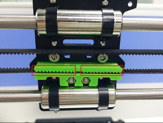
24 7 Mount the Y axis belt. Required parts Required number Part ID Pic Timing belt 1 NO.39 M3 x 10 screw 2 NO.25 M3 washer 2 NO.7 Step1. Drill a hole on one end of the belt(the hole can be as the diameter of the M3 screw, leave enough margin ) Step2. Fix the belt on one side of the belt -mount with a M3 x 10 screw and washer. Step3. Thread the belt around the pulley on the motor and the Y idler. Step4. Drill a hole on the other end of the belt and fix it on the belt -mount with a M3 x 10 screw and M3 washer. 23

25 *Tips: Shenzhen GETECH CO.,LTD 1. before you drill your second hole, make sure to pull belt tightly to make sure to find proper placement of hole for a tight belt, if it is too loose, it will hinder the move of t he print platform. 24

26 8 mount the End stop of Y-axis Required parts Required number Part ID Pic End stop 1 NO.56 M2.5 x 16 screw 2 NO.22 M2.5 Hex nut 2 NO.10 Mount the end stop on the rear support plate of Y axis with M2.5 X 16 screw and M2.5 Hex nut. 25


27 9 Assemble the right and left side panel Required parts Required number Part ID Pic XZ frame 1 NO.A1 Acrylic left frame 1 NO.A2 Acrylic right frame 1 NO.A3 M3 x 16 screw 6 NO.27 26

28 M3 square nut 6 NO.17 Step1. Screw up the X-Z frame and the side panel with M3 x 16 screws and M3 square nuts. 10 Mount the fan 27
29 Required parts Shenzhen GETECH CO.,LTD Required Part ID number Pic Fan 1 NO.53 M3 x 30 screw 4 NO.29 M3 locknut 4 NO.14 Fix the fan on the right side of the frame with 4 M3 x 30 screw and lock nut. Mind the direction of the wires. (Please pay attention to the direction of the fan) If you don t want to use the lock nut you can use hex nut. 28


30 11 Assemble the Z-axis bottom mount Required parts Required number Part ID Pic Z Motor fixed plate 1 NO.A4 Z Motor fixed plate 1 NO.A5 29


31 Z Motor support plate 3 NO.A6 Z Motor support plate 1 NO. A7 M3 x 16 screw 10 NO.27 M3 square nut 10 NO.17 Step1. It would be easier to mount the A4/A5 to A6 and A7 first, and then mount the assembled part to A1. Step2.Screw up the acrylic plates with M3 x 16 screws and M3 square nuts. *The right and left bottom mount are different; Please look at the following picture. 30

32 left right 31

33 12 Assemble Y - Z axis Shenzhen GETECH CO.,LTD Required parts Required number Part ID Pic M3 x 16 screw 2 NO.27 M3 x 20 screw 4 NO.28 M3 nut 4 NO.11 M3 square nut 2 NO.17 Step1. Put the Y axis into the main frame. Step2. Screw up the main frame to the acrylic fender with 4 M3 x 20 screws. And 32


34 screw up the M10 nuts. Shenzhen GETECH CO.,LTD Step3. Screw up the Y axis rear plate and the side panel with M3 x16mm screws and M3 square nuts. 33

35 13 Mount the End stop of Z-axis Shenzhen GETECH CO.,LTD Required parts Required number Part ID Pic End stop 1 NO.56 M 2.5 X 16 screw 2 NO.22 M 2.5 nut 2 NO.10 Mount the endstop on the outside of A7 with M2.5 x 16mm screw and M2.5 hex nut. 34

36 14 Assemble the 2 Z motors Shenzhen GETECH CO.,LTD Required parts Required number Part ID Pic Stepper Motor 2 NO.62 M3 x 12screw 8 NO.26 Step1.Thread the wires of the motors through the holes Step2. Screw up the motors with 4 M3 x 12 screws. Do the same with the other Z motor. 35


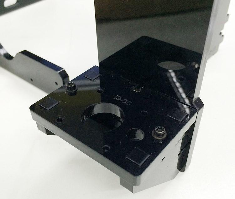
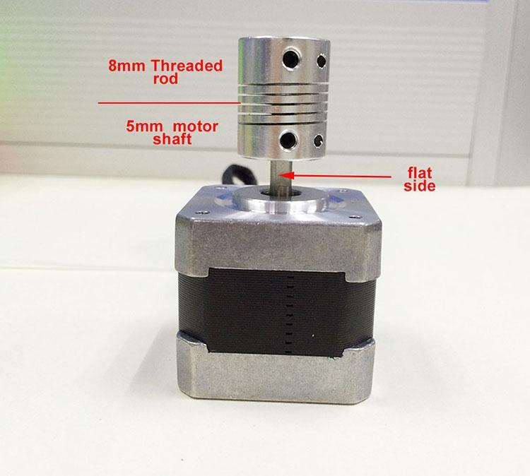
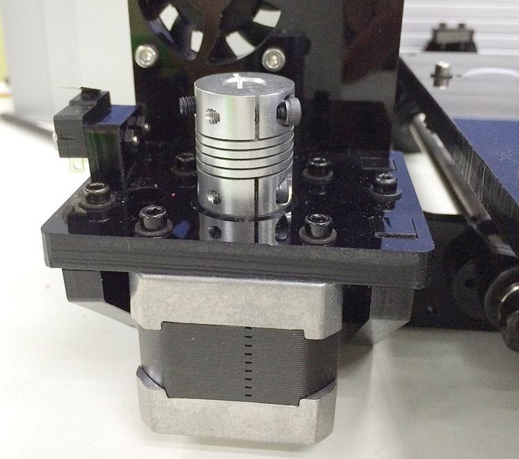
37 15 Assemble the coupling. Required parts Required number Part ID Pic Couplings 2 NO.43 Step1. Fix the two couplings on both of the motor shaft. Please note: 1. The opening of both end, one is 5mm, another is 8mm, connect the 5mm hole to the motor shaft. 2. Screw the small bolt of the 5mm part on the upper part of the flat side of the motor shaft tightly. 36
38 37

39 16 Attach he heated bed. Required parts Required number Part ID Pic Heat bed set 1 NO.59 M3 x35 screw 4 NO.30 M3 washer 12 NO.7 Spring 4 NO.35 clamp 4 NO.48 38

40 Wing nut 4 NO.16 Borosilicate glass 1 NO.60 *All our heated bed is pre-soldered or attached before shipping; you can attach the bed directly here. Mount the heat bed on the platform with 4 M3 x35 screws and wing nuts with springs in between. Clamp the heat bed and the glass sheet. *the soldered side is better to be attached downwards. 39


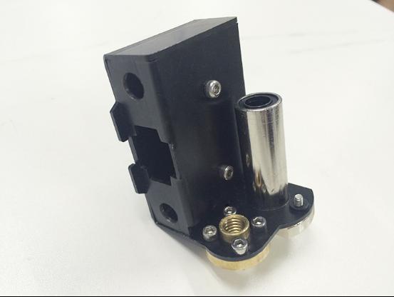
41 17 Mount the X-axis motor end Part name Part ID Required number pic Z-axis nut No.18 1 X-axis motor end No.M1 1 Linear Bearing LMH8LUU No M3 x 30 screw No

42 M3 x 6mm screw No M3 washer No. 7 2 \ Spring No Step1. Mount the Z nut on the X-axis left end from bottom to up, fix with M3 x 6mm screws. Step2. Mount the linear bearing on X-axis motor end from bottom to up. Fix it up with M3 x 6mm screws. Mount the endstop trigger 1. Thread a M3 washer> spring> M3 washer in order to the M3x30mm screw. 2. Thread half of the M3x30mm screw into the screw hole. Mount the X motor 41

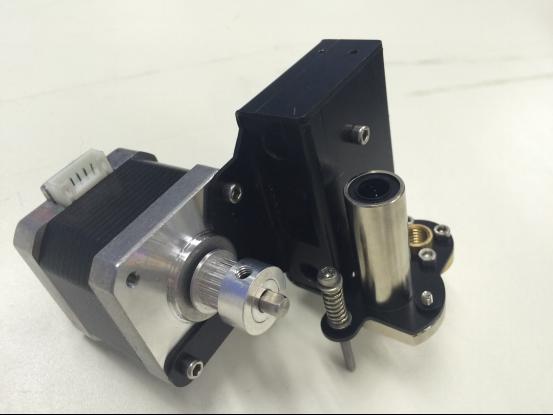
43 Part name Part ID Required number pic M3 x 6 mm screw No Stepper motor No.62 1 Pulley No.44 1 Note: In some of the picture, the pulley is a bit different but it won t affect your assembly. Step1. Mount the pulley on the motor shaft. Screw it on the flat side. Step2.Mount the stepper motor on the motor end with 3 M3 x 6 mm screw. 42

44 Mount the endstop 43

45 Part name Part ID Required number pic M2.5 x 8 mm screw No End stop No.56 1 Mount the endstop on the top of X-axis motor end with two M2.5 x 8mm screws 44
 For the whole process of assembly of this part,")

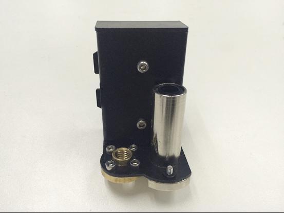
46 18 Assemble the right end of the X axis. (X idler end) For the whole process of assembly of this part, please refer to the video here. Part name Part ID Required number pic Z-axis nut No.18 1 X-axis idle end No.M2 1 Linear Bearing No LMH8LUU 45
47 M3 x 6mm screw No Step1.Mount the Z axis nut on the bottom of X-axis right end with 4 M3 x 6mm screws. Step2. Mount the linear bearing on X-axis motor end from bottom to up. Fix it up with M3 x 6mm screws. 46
48 47
49 19 Assembly of the extruder carriage Part name Part ID Required number pic X Carriage No.M3 1 Bearing Bracket No.M4 4 Extruder holder No.M5 1 Linear Bearing LM8LUU No.37 2 Belt bracket No.51 1 M3x6mm screw No M3x12mm screw No M4x6mm screw No M3 nut No.11 2 Step1. Fix the 4 Bearing Brackets on the back of the X Carriage loosely with M3x6mm screws. Insert the linear bearing into the slot and screw the bracket tightly. 48

50 Please notice the front and back of the plate. Step2. Fix the belt mount on the back of the carriage with 2 M3x 12mm screws and M3 hex nuts. Step3. Fix the extruder holder on the front side of the X carriage using M4x6mm screws. 49

51 20 Assemble the X&Z axis Part name Part ID Required number pic L300mm threaded rod L322mm smooth rod L410mm smooth rod locking ring No.4 2 No.1 2 No.3 2 No

52 Step1. Thread the L300 threaded rod to the nut of both end of X axis. Keep both end of X axis at the same place of the rod, you are advised to measure the distance of the both side so that they are at the same level when you put them up. Step2. Plug the threaded rod on the X motor end to the left coupling on the left bottom of the Z axis. Then thread the 320mm smooth rod into the linear bearing. 51

53 Step3. Thread the L410mm smooth rod into the X motor end > thread the extruder carriage on the two rods. 52

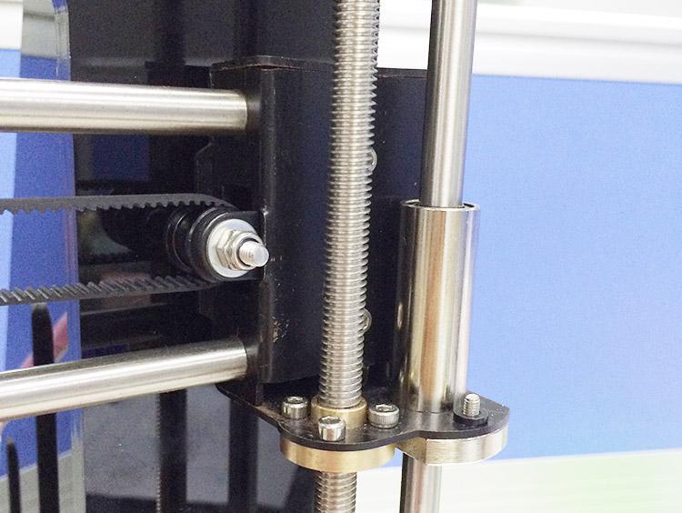
54 Step4. Thread the two X axis smooth rods into the hole of X idler end. Plug the vertical threaded rod into the coupling on the right bottom of the Z axis. Then thread the 340mm smooth rod into the linear bearing. 53

55 Note: the smooth rods and the threaded rod of Z axis are vertical and the X axis is horizontal, which is very important, or it will hinder the move of the Z axis. Step5. Fix the locking rings on the end of the rod if you got the silver rings. 54
56 NOTE: If you got the black lock ring (No.20), you need to fix all the 4 locking rings on the right end, as shown on the following picture. 55

57 21 Assemble the Z axis top mount Part name Part ID Required number pic Z top mount No.A8 2 M3 x 16mm screw No.27 4 M3 Square nut No.17 4 locking ring No

58 M3 washer No. 7 6 \ Step1. Put the locking ring on the two smooth rods separately. Step2. Add the Z top mount (No.A8) to the top of A1. Slowly rotate the rods into the holes, or add some lubricants on the rods. Do not force it, or u will break the acrylic piece. Step3. Screw it up with M3 x 16mm screw and M3 Square nut. Step4. Screw up the locking ring on smooth rods. 57


59 22 Mount the extruder Required parts Required Number Part ID Pic MK8 extruder 1 NO.63 M4 x 6mm screw 2 NO.32 M4 washer 2 NO.8 Step1. Mount the assembled extruder on the extruder support. Use 2 M4 x 6 mm screws and M4 washers to fix. 58

60 23 X belt driving wheel Part name Part ID Required number pic Driven wheel holder No.41 1 Driven wheel No.45 1 MR84zz Ball Bearing No.46 2 M3 x40mm screw No.31 1 M4 x 25mm screw No.33 1 M3 washer No

61 M4 washer No.8 1 M4 lock nut No.15 1 wing nut No.16 1 Step1. Thread the M3 x 40 screw and M3 washer through the Driven wheel holder. Step2. Insert the two MR84zz ball bearings into both ends of the driving wheel. For your convenience, this step is already finished by us. 60
62 61
63 Step3. Put the M4 x25 screw and M4 washer through the driving wheel. Lock the other end with a M4 lock nut. You may need a wrench to tighten locking nut. 62

64 *Do not screw it too tight, you should leave enough room for the wheel to turn freely. 24 Add the belt Part name Part ID Required number pic Timing belt No.40 1 Step1. Insert one end of the belt in the groove. Pay attention to the tooth mesh of the belt and the groove. Step2. Thread another end of the belt through the X motor end around the pulley. Step3. Threaded the belt through the belt driving wheel and put the driving wheel into the X idler end, lock it with a wing nut. Step4. Insert another end of the belt into the groove. Cut the spare part. Be sure of the length of the belt. Step5. Taut the belt and tighten the wing nut on the idle end. 63
65 64
66 65
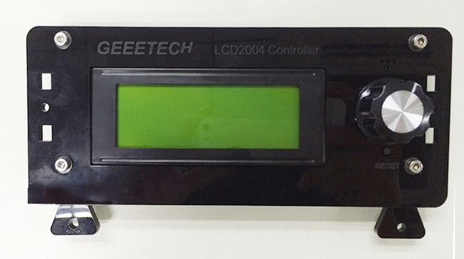
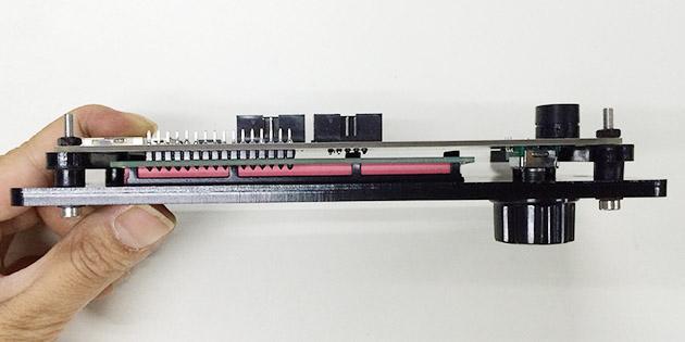
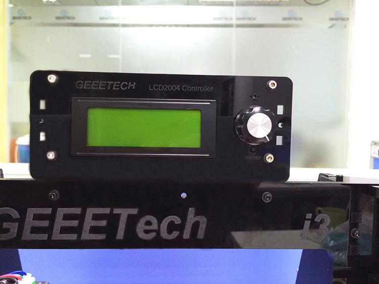
67 *Note the direction of the driving wheel, the side with bolt head should be towards the A1, or it will scratch the acrylic plate. 25 Mount the LCD panel frame. Required parts Required number Part ID Pic LCD NO.65 LCD frame 1 NO.A18 LCD frame holder 2 NO.A19 Acrylic washer 4 NO.A17 M3 x 20 screw 6 NO.28 M3 nut 4 NO.11 Knob 1 NO.52 66
68 67
69 68

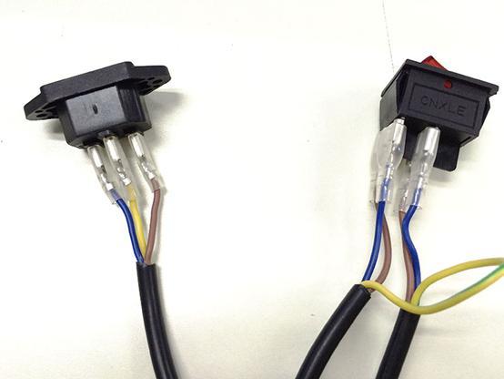
70 26 Mount the PSU Shenzhen GETECH CO.,LTD Required parts Required number Part ID Pic Power supply 1 NO.61 M3 x 10 screw 3 NO.25 M3 x 16 bolt 2 NO.34 M3 nut 2 NO.11 3D Power cable 1 NO.57 Power Cable 1 NO.58 Step1. Take off the wires connected to the socket; before you do, please take a photo of the wire connection, in case you connect them wrongly later. 69
71 70
72 71


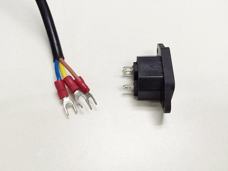
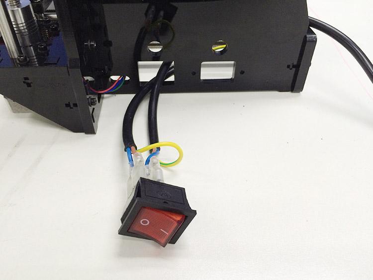
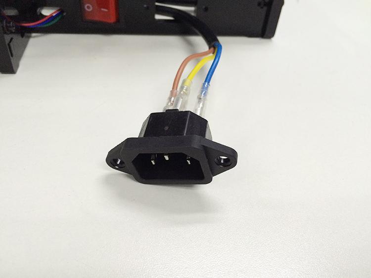
73 Step2. Mount the socket on the bottom of the right side panel with 2 M3 x 16 Hex Counter- sunk-head screws and M3 hex nut. Step3. Thread the wires out. Step3. Mount the PSU (Power supply unit) on the right side panel with 3 M3 x 10 72

74 screws. Shenzhen GETECH CO.,LTD Step5. Now we can connect the wires to the PSU. 1) Mind the color of the wires. The wrong connection of the wire will cause serious damage to the PSU and even to the control board of the printer. As you can see, there are 7 wires and 7 screws in total. Note the correspondence between the color of wires and the connector. Brown------L Blue N Yellow GND Red V Black------COM 73


75 2) Pay attention to the switch on the right side of the PSU, there are two options of voltage: 110 V and 220V, choose according the standard in your country. As shown in the following picture. Remove the yellow paper; you can use some hard sticks to reach the switch. 74
. The sticker is double sided adhesive. Step3.")
76 Close the cover of the connector in case any electric shock. 27 Mount the control board Part name Part ID Required number pic Control board kit No.64 1 Sticker No.50 1 Heat sink No.49 1 Spacer No.47 4 M3 x 12 mm screw No.26 4 Step1. Cut the sticker into small pieces. Step2. Past the heat sink onto the chip of the A4988 drivers (on the main board). The sticker is double sided adhesive. Step3. Insert the spacer into the holes of the board from back to front, Mount the board kit on the left side panel with 4 M3 x 16mm screws and M3 washers on the side panel. Note the direction of the board; the green connectors are downwards to get enough heat dissipation from the fan. 75

77 28 Wiring GT2560 Before you start wiring, please take a look at the wiring schematics. 76

78 You can see original picture here. Step1. The subdivision of stepper motor can be setup by jumper cap, plug all the jumper caps (For A4988) 77

79 If you are using DRV8825 instead of A4988, the jumper caps should be changed as follow: Note please, as your printer is single extruder, you will not use the extruder 2. 78

80 Step2. Plug the 4 A4988 into the stepper motor driver slot. Mind the directions of A


81 If you are using DRV8825 instead of A4988, The correct connections are as follow: For your convenience, the above two steps is finished by us. you can skip them. 80
 Connect wires for X-axis motor. Shenzhen GETECH CO.")
82 Step3. Connect wires for motors. 1) Connect wires for X-axis motor. Shenzhen GETECH CO.,LTD 2) Connect wires for Y-axis motor. 81
83 3) Connect wires for 2 Z-axis motors. Shenzhen GETECH CO.,LTD 82

84 4) Connect Extruder motors. You can connect the extruder to either of the motor slot. 83

 Connect heating")
85 Step4. Connect heating wires. Loosed the screws in the green terminal and put the red wires into the slot and screw it up. * There is no + and - for heating wires 1) Connect heating wires for heatbed. 2) Connect heating wires for extruder 1. 84

 Connect wires for thermistor of")
86 3) Connect heating wires for extruder 2. Step4. Connect wires for thermistor. 1) Connect wires for thermistor of heatbed. 2) Connect wires for thermistor of extruder 1. 85


87 3) Connect wires for thermistor of extruder 2. 86
88 Step5. Connect wires for endstop. * There is no + and - for endstop 1) Connect wires for endstop of X-axis at X-Min. 2) Connect wires for endstop of Y-axis at Y-Min. 3) Connect wires for endstop of Z-axis at Z-Min. 87


89 Step6. Connect wires for Fan. 1) Connect fan for control board at FAN3. 2) Connect fan for extruder at FAN1. 88

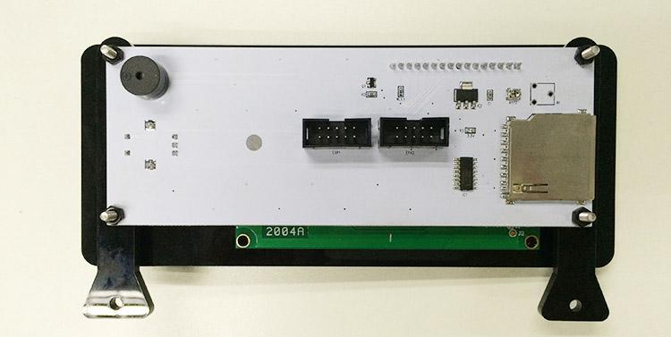
90 Step7. Connect wires for LCD panel. There are two cables, one is for LCD encoder, the other is for SD card, do not connect them reversed. EXP1 to LCD EXP2 to SD card BTW, do you see the small screw above the SD card reader, if the text in of the LCD phases in an out or there is only blocks on the screen, you can adjust this screw to recovery it. 89


91 Step8. Connect wires for power input. 90


92 That is all for the wiring of GT Tidy out the wires. Use the wire coil to tie put those wires together. There are holes on the acrylic plates for the wires, you can arrange them as you like. 30 Mount the filament spool. Required parts Required number Part ID Pic Filament side panel M3 x 16 screw 4 NO.27 M3 square nut 4 NO.17 91

93 PVC tube 2 The whole printer assembly work is already done. 31 Tips Before even attempting the first print it is vital that the printer is correctly calibrated. Skipping or rushing this step will result in frustration and failed prints later, so it is important to take the time to make sure the machine is correctly set up. Each machine may have its own calibration procedure and this manual will not attempt to cover all the variations. Instead here is a list of key points that should be 92
94 addressed. Shenzhen GETECH CO.,LTD Frame is stable and correctly aligned. Rods are correctly aligned Belts are taut. Driving wheel turns smoothly Bed is level in relation to the path of the extruder. Filament rolls freely from the spool, without causing too much tension on the extruder. Current for stepper motors is set to the correct level. Wires are correctly connected Couplings and pulleys are fixed tightly Firmware settings are correct including: axis movement speeds and acceleration; temperature control; end-stops; motor directions. Extruder is calibrated in the firmware with the correct steps per mm of filament. The point regarding the extruder step rate is vital. Slic3r expects that the machine will accurately produce a set amount of filament when told to do so. Too much will result in blobs and other imperfections in the print, too little will result in gaps and poor inter-layer adhesion. For how to set up the printer, please visit: To know how to set up, please refer to the user manual. 93
Assemble Instruction of Geeetech Acrylic. Prusa I3 Pro C
 Assemble Instruction of Geeetech Acrylic Prusa I3 Pro C Version 04-11-2016 Safety Instructions Building the printer will require a certain amount of physical dexterity, common sense and a thorough understanding
Assemble Instruction of Geeetech Acrylic Prusa I3. pro C
 Assemble Instruction of Geeetech Acrylic Prusa I3 pro C Safety Instructions Shenzhen GETECH CO.,LTD Building the printer will require a certain amount of physical dexterity, common sense and a thorough
Shenzhen GETECH CO.,LTD GEEETECH. Building Instructions of Geeetech Prusa I3 X
 Building Instructions of Geeetech Prusa I3 X CONTENT CONTENT... 2 Safety Instructions...3 Preparation...4 Unfold the box and check the package list... 5 1. Assemble the threaded rods of Y axis... 6 2.
Delta Rostock mini G2& G2s Building instruction
 Delta Rostock mini G2& G2s Building instruction Safety Instructions ShenZhen GETECH CO.,LTD Building the printer will require a certain amount of physical dexterity, common sense and a thorough understanding
Geeetech Delta Rostock mini G2 pro / G2s pro Building Instruction
 Geeetech Delta Rostock mini G2 pro / G2s pro Building Instruction (Document version: 04-11, 2016) CONTENT Safety Instructions... 1 Preparation... 2 1 Base Assembly... 3 1.1 Motor holder assembly... 3 1.2
Geeetech A30 3D Printer Building Instruction
 Geeetech A30 3D Printer Building Instruction Contents Safety Instructions... 1 Preparation... 2 1. Unfold the Box and Check the Package... 3 2. Assembly... 4 3. Wiring... 9 4. Warm Tips...16 Safety Instructions
Geeetech Acrylic I3 Pro C 3D Printer
 Geeetech Acrylic I3 Pro C 3D Printer Copyright Declaration The copyright of this manual belongs to the Shenzhen GETECH CO., LTD. (hereinafter referred to as the "Geeetech"), and all rights reserved. No
Kossel Rev B Build Guide V1.0
 Kossel Rev B Build Guide V1.0 1 Table of Contents: Step 1: BASE ASSEMBLY Gathering parts: Building the Corners and Base: Step 2: UPPER ASSEMBLY Building Upper: Step 3: VERTICAL RAIL INSTALLATION Building
Code Product Qty 1 Top Vertex 3 2 Hot End Housing 1 3 Bottom Vertex 3 4 Print Platform Lock 3 5 End Stop Holder 3 6 Filament Feeder Motor Bracket 1 7
 List of Parts Code Product Qty 1 680mm Extrusion 3 2 Power Supply 1 3 240mm Extrusion 9 4 42mm Nema 17 Stepper Motor 3 5 Slider-Hotend Connecting Rod 6 6 48mm Nema 17 Stepper Motor 1 7 Linear Rail with
(Assembling Guide supplied by imakr ) with the support of MyMiniFactory.com
 with the support of MyMiniFactory.com") (Assembling Guide supplied by imakr ) with the support of MyMiniFactory.com Summary Congratulations on beginning on your journey into 3D printing with the STARTT 3D printer. In this guide, you will have
(Assembling Guide supplied by imakr ) with the support of MyMiniFactory.com Summary Congratulations on beginning on your journey into 3D printing with the STARTT 3D printer. In this guide, you will have
M2 Assembly. M2 Sub-Assemblies mm Belt Sub-Assembly mm Belt Sub-Assembly Spider Sub-Assembly... 4
 M2 Assembly Table of Contents M2 Sub-Assemblies... 3 630mm Belt Sub-Assembly... 3 702mm Belt Sub-Assembly... 3 Spider Sub-Assembly... 4 Idler Bolt Sub-Assembly... 8 Y Motor Sub-Assembly... 9 X Motor Sub-Assembly...
Part 7 Assembling the X axis
 Part 7 Assembling the X axis 1 2 The X axis is a key part of the printer, it carries the extruder on a carriage that moves the extruder laterally in the X axis. The x axis itself is moved vertically on
AM8 Printer A metal frame for your Anet A8 By Pheneeny v1.0 April 20, 2017
 AM8 Printer A metal frame for your Anet A8 By Pheneeny v1.0 April 20, 2017 Please read this entire document before printing parts or building this frame Disclaimer: This guide is for informational purposes
V4 Premium Kit. Prusa i3 Build Guide
 V4 Premium Kit Prusa i3 Build Guide Hi! Congratulations on your purchase of the DIYElectronics.co.za Prusa I3 kit, the best South African 3D Printer Kit! Hopefully this should serve as complete guide to
Ender-3 3D Printer. Instructions for assembly
 Ender-3 3D Printer Instructions for assembly This guide is for the Ender-3 3D printer. Select the correct input voltage to match your local mains (220V or 110V). Because of software/hardware upgrades and
ABM International, Inc. Navigator Assembly Manual
 ABM International, Inc. 1 1.0: Parts List Tablet (Qty. 1) Tablet mount (Qty. 1) NOTE: Mount may appear and operate different then image below Control Box (Qty. 1) Motor Power Supply (Qty. 1) 2 X-axis motor
BIGBOT ASSEMBLY INSTRUCTIONS. 1/18/2017 V0.5
 BIGBOT ASSEMBLY INSTRUCTIONS www.bigbot-3d.com 1/18/2017 V0.5 FOREWORD: PLEASE TAKE CARE WHEN HANDLING THE GANTRY. THE ASSEMBLY SHOULD BE HANDLED ONLY BY THE ALUMINUM FRAME, AND AVOID TOUCHING OR LIFTING
Step 1 Assemble Base Frame
 Step 1 Assemble Base Frame Parts: 2040 Aluminium profile 250mm 1pcs Base Plate 1pcs M4-8mm screw 3pcs M4 T-Nut 3pcs Put the aluminium profile on the base plate, secure them with 3pcs M4-10mm screws & T-Nut
Assembly Guide for Printrbot - Simple Maker s Edition 1405
 Assembly Guide for Printrbot - Simple Maker s Edition 1405 Last update: March 2016 Please Note: be careful on the steps that are underlined 1 Contents Tools Needed:... 3 First step: Check components and
INVENT3D Printer Kit Disassembly Instructions
 INVENT3D Printer Kit Disassembly Instructions Version 6 AST2 10/26/16 1 I. General Disassembly Instructions Use the case layer drawings to ensure that components are stored in the appropriate location
Step 1 Assemble Base Frame Parts: 2040 Aluminium profile 250mm 1pcs Base Plate 1pcs M4-8mm screw 3pcs M4 T-Nut 3pcs
 Step 1 Assemble Base Frame 2040 Aluminium profile 250mm 1pcs Base Plate 1pcs M4-8mm screw 3pcs M4 T-Nut 3pcs Put the aluminium profile on the base plate, secure them with 3pcs M4-10mm screws & T-Nut Step
LYMANBOT 3D PRINTER V3 Construction Manual
 LYMANBOT 3D PRINTER V3 Construction Manual Page 1 Read this whole Manual before starting to construct this Printer. User excepts all liability for the use of this Manual and the construction of this Printer.
Printrbot Simple (Model 1403) Rev F Printrboard
 Rev F Printrboard") Printrbot Simple (Model 1403) Rev F Printrboard Printrbot Simple is currently shipping with the Rev F Printrboard. Check which rev Printrboard your Simple kit includes and use the corresponding instructions.
Printrbot Simple (Model 1403) Rev F Printrboard Printrbot Simple is currently shipping with the Rev F Printrboard. Check which rev Printrboard your Simple kit includes and use the corresponding instructions.
The Portable Open Source 3D Printer
 http://web.archive.org/web/201502142011/http://www.tantillus.org/build_3.html Page 1 of 12 captures 12 Oct 12 - Feb 15 The Portable Open Source 3D Printer Home Start Case X/Y Axis Extruder Z Axis Electronics
Assembly Instructions. Beta Prusa DualX 3D Printer
 Assembly Instructions Beta Prusa DualX 3D Printer Version 2.6 Date Page 1 / 72 General data about the assembly instructions for an incomplete machine according to appendix VI of the EG machinery directive
Assembly Instructions Beta Prusa Standard & Deluxe
 Assembly Instructions Beta Prusa Standard & Deluxe 3D Printer Version 2.6 Date Page 1 / 67 General data about the assembly instructions for an incomplete machine according to appendix VI of the EG machinery
re3d Assembling Gigabot: "Flatpack"
 re3d Assembling Gigabot: "Flatpack" Your Gigabot was assembled, calibrated, tested, and taken apart for shipping purposes. All you need to do is reassemble it, and you're ready to go! Written By: Chris
3. X-axis assembly. 3. X-axis assembly. Written By: Jakub Dolezal manual.prusa3d.com/ Page 1 of 13
 3. X-axis assembly Written By: Jakub Dolezal 2018 manual.prusa3d.com/ Page 1 of 13 Step 1 Tools necessary for this chapter Needle-nose pliers for zip tie trimming. 2.5mm Allen key for M3 screws 2mm Allen
5. Extruder Assembly
 5. Extruder Assembly Guide for the assembly of the Extruder. Written By: Josef Prusa 2017 manual.prusa3d.com Page 1 of 22 Step 1 Get the necessary tools 2.5 and 1.5 mm Allen key Needle-nose pliers Step
Assembly Instructions
 P/N 8650/8655 Assembly Instructions NOTE: Your Sherline CNC Cam Grinder is double boxed and secured to a wooden shipping frame. Upon delivery, check the outer box for damage. If the box is damaged, take
HQ Pole Upgrade Kit for HQ Adjustable Table and HQ QuilTable Assembly Instructions 1
 HQ Pole Upgrade Kit for HQ Adjustable Table and HQ QuilTable Assembly Instructions QF09775 The pole upgrade kit can be used with or without the QF09700 HQ Precison-Glide track upgrade kit. What s Included
Written By: Brook Drumm
 Simple 1401 Assembly For kits produced between 1/15/14-6/1/14. This guide is for kits with the Fan Shroud. Instructions for metal and wood extruder (and bed) included below. Written By: Brook Drumm TOOLS:
Assembly Instructions
 Assembly Instructions Note: Prior to assembly, be sure to remove all printing pads from the printed parts and also be sure to sort through and organize all of your hardware before assembly this will help
Heacent 3D printer assembly manual. Prusa i3
 Heacent 3D printer assembly manual Prusa i3 Y-axis assembly 1. Y axis motor section: Find the belowing parts bag, Y-axis motor Assembled parts are separated as shown below, note that the motor between
3D PRINTER. Pack 11. Anything you can imagine, you can make! 3D technology is now available for you at home! BUILD YOUR OWN
 BUILD YOUR OWN Pack 11 Anything you can imagine, you can make! 3D PRINTER Compatible with Windows 7 & 8 Mac OS X 3D technology is now available for you at home! BUILD YOUR OWN 3D PRINTER CONTENTS PACK
0. Disassembly. Disassembly of the MK2 printer and upgrading to the MK2S using the upgrade kit. Written By: Jakub Dolezal
 0. Disassembly Disassembly of the MK2 printer and upgrading to the MK2S using the upgrade kit. Written By: Jakub Dolezal 2018 manual.prusa3d.com/ Page 1 of 12 Step 1 Preparing the printer Ensure the printer
This manual will aid in the assembly of the FireBall V90 and FireBall X90. The assembly of both machines will be identical, unless specified.
 This manual will aid in the assembly of the FireBall V90 and FireBall X90. The assembly of both machines will be identical, unless specified. Step #1 Lay all parts out to verify quantities. (2) 2 x 25-1/4
Electric Skein Winder
 Electric Skein Winder Assembly and Use Package Contents 1 - Triangular Body (w/ motor) 1 - Cross Arm 1 - Left Foot (w/ yarn guide) 1 - Right Foot 1 - Adjustable Finger (w/ yarn clip) 3 - Adjustable Fingers
Assembly Instructions Beta Prusa Standard & Deluxe
 13/11/12 Assembly Instructions Beta Prusa Standard & Deluxe 3D Printer Version 1.0 Date 13/11/12 Page 1 / 66 General data about the assembly instructions for an incomplete machine according to appendix
Assembly Instructions
 Assembly Instructions Note: Prior to assembly, be sure to remove all printing pads from the printed parts and also be sure to sort through and organize all of your hardware before assembly this will help
Titan Aero Assembly. Titan Aero Assembly. Learn to assemble your Titan Aero. Written By: Gabe S e3d-online.dozuki.
 Titan Aero Assembly Learn to assemble your Titan Aero Written By: Gabe S. 2018 e3d-online.dozuki.com/ Page 1 of 26 INTRODUCTION The Titan Aero is a very similar build to a Titan and a V6 put together (which
4. Z-axis assembly. 4. Z-axis assembly. Written By: Josef Prusa manual.prusa3d.com Page 1 of 18
 4. Z-axis assembly Written By: Josef Prusa 2017 manual.prusa3d.com Page 1 of 18 Step 1 Get the necessary tools 13/17mm spanners 3.6mm flathead screwdriver Needle-nose pliers 2.5 and 1.5mm Allen key Step
Shapeoko XXL Assembly Guide
 Shapeoko XXL Assembly Guide 04/27/2016 XXL Packing LIst Item Qty Description Y-Carriage (left) 1 Y-Carriage (right) 1 X/Z Assembly 1 40 Rail 3 1 rail has mounting holes for controller Wasteboard Half 2
Classification Of Screws
 Classification Of Screws M3 nuts 60pcs M3*20mm screws 58pcs M2.5*10mm black screws 2pcs M8 nuts 12pcs M3*10mm screws 17pcs M3*30mm screws 7pcs M8 Cushion ring 12pcs M3*14mm screws 4pcs Plastic Pillars
Nancy s Knit Knacks LLC 4 Yard Option Upgrade Kit Assembly Instructions and User Manual
 Nancy s Knit Knacks LLC 4 Yard Option Upgrade Kit Assembly Instructions and User Manual Thank you for purchasing our 4 Yard Option (4YO) Upgrade Kit. To install this upgrade you are simply going to assemble
Welcome! Table of Contents
 Welcome! The folks at Random Idea Generator Shop would like to thank you for purchasing our 3D printer kit. We are dedicated to providing an easy to build kit with customizable options to meet your requirements.
SatNOGS. SatNOGS Rotator v3 Mechanical Assembly. This is the assembly guide for the third version of the SatNOGS Rotator.
 SatNOGS SatNOGS Rotator v3 Mechanical Assembly This is the assembly guide for the third version of the SatNOGS Rotator. Written By: Pierros Papadeas 2017 satnogs.dozuki.com Page 1 of 19 INTRODUCTION Notes:
Continuum Frame Assembly Instructions
 Continuum Frame Assembly Instructions Copyright January 1, 2017 Jim M. Bagley, GraceWood, Inc (Reproduction Prohibited) Version 2.2 Table of Contents Continuum Frame Table of Contents... i Warranty...ii
Be sure any accessory used will fit with the soft upper doors before installing. Not all accessories will be compatible.
 Company Name: Spike Power Sports Vehicle Name: Polaris General 2P Product Description: Soft Upper Doors Part Number: 58-1600 Revision: R01 09/19/2018 Contents: 655 Elm Ridge Ave, Canal Fulton OH, 44614
Lead Screw Upgrade. How to upgrade your ROBO R1 to the new Lead Screw Upgrade Pack. Written By: Harrison Team RoBo 3D
 Lead Screw Upgrade How to upgrade your ROBO R1 to the new Lead Screw Upgrade Pack. Written By: Harrison Team RoBo 3D 2017 guide.robo3d.com Page 1 of 14 Step 1 Lead Screw Upgrade Begin by powering off and
ABM International, Inc.
 ABM International, Inc. Lightning Stitch required 1 1.0: Parts List head and motor assembly (Qty. 1) Reel stand (Qty. 1) Needle bar frame clamp (Qty. 1) Motor drive (Qty. 1) 2 Cable harness with bracket
E3 CNC Router Assembly Instructions
 E3 CNC Router Assembly Instructions Specifications... 3 Getting Started... 3 Safety First... 3 Required Tools... 4 Building the E3 CNC Engraver... 4 1. Z Spindle Mount Assembly... 5 3. Frame Assembly...
BABY WOLF LOOM. Assembly Instructions for Knocked-Down Looms
 BABY WOLF LOOM Assembly Instructions for Knocked-Down Looms BEFORE YOU BEGIN Please read through the directions before beginning to assemble your loom. Unpack the loom parts carefully. Do not throw away
Document version: 1.1. Beagle Build manual
 Document version: 1.1 Beagle Build manual TABLE OF CONTENTS Table of contents...2 About the Beagle...3 Change history...4 Safety warnings...4 Required tools...5 1. Bars & Printed parts examination...6
Q-Zone Hoop-Frame. Assembly Instructions. Copyright July 11, 2018 Grace Company (Reproduction Prohibited) Version 1.8
 Version 1.8") Q-Zone Hoop-Frame Assembly Instructions Copyright July 11, 2018 Grace Company (Reproduction Prohibited) Version 1.8 Table of Contents Table of Contents... i Warranty... ii Parts List Box 1...iii Box 2...
Q-Zone Hoop-Frame Assembly Instructions Copyright July 11, 2018 Grace Company (Reproduction Prohibited) Version 1.8 Table of Contents Table of Contents... i Warranty... ii Parts List Box 1...iii Box 2...
The Queen Quilter Professional Quilters Kit Frame
 The Queen Quilter Professional Quilters Kit Frame Assembly Instructions Table of Contents: Before you begin......................... Pg. 2 Wood parts............................. Pg. 3 Hardware..............................
Depending on the size you ordered you will have either 5 Foot sections which will build the 10 Foot frame or 6 Foot sections which will build the 12
 XL Quilting Frame 1 Depending on the size you ordered you will have either 5 Foot sections which will build the 10 Foot frame or 6 Foot sections which will build the 12 Foot frame Printed 2 June 2014 Updated
Legacy Woodworking Machinery a division of Phantom Engineering. The Legacy CNC. Assembly Manual
 Legacy Woodworking Machinery a division of Phantom Engineering The Legacy CNC Assembly Manual New Orientation of the Legacy Step one: Re-orientation of the machine Remove the X-axis screw and supports.
Metroboard Pulley Replacement Procedure
 Metroboard Pulley Replacement Procedure 1) Remove the two transmission cover screws (1/8 allen driver). Then remove the transmission cover. Note there is a split lock washer and flat washer as well, so
1.75mm Direct Titan Assembly
 1.75mm Direct Titan Assembly Learn how to assemble your Titan for use with 1.75mm filament in a direct configuration. Written By: Gabe S. 2018 e3d-online.dozuki.com/ Page 1 of 20 TOOLS: Hex Wrench, 1.5mm
F400 QUICK-START GUIDE
 F400 QUICK-START GUIDE PLEASE READ THIS DOCUMENT BEFORE OPERATING YOUR PRINTER Revision 10-1/31/18 Page 1 Table of Contents 1. Introduction... 3 2. What s in the Box... 3 3. Unboxing Your F400... 4 4.
WARNING Indicates a hazardous situation which, if not avoided, could result in death or serious injury. WARNING. Ranger XP Door Kit
 REVISION 04 November, 20 2018 Ranger XP Door Kit Prior to installation, please verify if a revised version of this instruction sheet is available on Knowledge Center. The following symbols may be used
Tools: Sharpie, Square, Vise, Hack saw, Ruler, Punch, Hammer, File. 2. Cut the stock Place stock in vise and cut with hack saw
 Purpose: MAKE CATAPULT ARM Step 1 Tools: Sharpie, Square, Vise, Hack saw, Ruler, Punch, Hammer, File Materials: Flat aluminum ½ inch stock (see picture below) Gloves required 1. Pick up the aluminum ½
CRP700 Benchtop Basic CNC Machine Assembly Instructions. Updated 10/24/2014 SHEET 1 of 24
 CRP700 Benchtop Basic CNC Machine Assembly Instructions Updated 0//0 SHEET of NOTE: This piece of extrusion is mounted wide side up Quick Tip: Lay extrusion on table as shown for easy assembly BASE ASSEMBLY:.
PRS Retro Z-Axis Installation
 PRS Retro Z-Axis Installation Page -1- PRS Retro Z-Axis Installation This document is a guide to installing the PRS Retro Z-axis on early ShopBot models. It describes installation for PR models with PK299
IMPORTANT SAFETY INSTRUCTIONS
 ASSEMBLY MANUAL IMPORTANT SAFETY INSTRUCTIONS! WARNING SHARP EDGES Use caution during assembly and operation of the 3D printer to ensure no sharp edges will cut you. Inspect the printer for any damage
25-200H. 12 Planer / Jointer. with Helical Cutterhead. Parts List.
 25-200H 12 Planer / Jointer with Helical Cutterhead 4001824 Parts List www.rikontools.com CABINET ASSEMBLY PARTS EXPLOSION & PARTS LIST KEY NO. DESCRIPTION KEY NO. DESCRIPTION 1 Pan Head Screw M6x12 P25-200H-1
EllisSaw.com. EllisSaw.com P.O. Box Verona, WI
 P.O. Box 9019 Verona, WI 9-019 GENERAL OPERATING & SAFETY INSTRUCTIONS * READ INSTRUCTIONS BEFORE USE * CAUTION: Disconnect power supply cord from power source when doing repair work or changing belt.
Elimination of Elevator Bounce
 For the Agilent Archon Autosampler Rework Instructions CAUTION This kit is intended for use by Agilent Service personnel only. Elevator Removal 1 Open top cover. 2 Open front lower door. 3 Remove vial
Removing the Z-Axis lead screw
 Page 1 of 8 TITLE: Sabre Z-Axis Lead Screw Replacement Procedure Gerber FastFact #: 5048 Supplied by: Gerber Hardware Support Last Modified: June 14, 2007 Summary: Tools used: The following procedure explains
The Phoenix. Professional Quilting Frame. Copyright January 1, 2016 Jim M. Bagley, GraceWood, Inc (Reproduction Prohibited) Version 2.
 Version 2.") The Phoenix Professional Quilting Frame Copyright January 1, 2016 Jim M. Bagley, GraceWood, Inc (Reproduction Prohibited) Version 2.1 1 The Phoenix Professional Quilting Frame Parts List Box 1...3 Box
The Phoenix Professional Quilting Frame Copyright January 1, 2016 Jim M. Bagley, GraceWood, Inc (Reproduction Prohibited) Version 2.1 1 The Phoenix Professional Quilting Frame Parts List Box 1...3 Box
Warnings. Description. Prior to Installation Tools Needed
 Warnings Failure to act in accordance with the following may result in death or personal injury. The JT Strong Arm Stabilizer System is intended to eliminate chassis movement in travel trailers and fifth
Juki Quilting Frame. Assembly and Use Instruction Manual. Max Overall Dimensions: Length Crib: King: Tall: Wide: 42
 Juki Quilting Frame Assembly and Use Instruction Manual Max Overall Dimensions: Length Crib: 63 1 4 King: 128 1 4 Tall: 45 3 4-51 3 4 Wide: 42 Copyright January, 2015 Version 9.6 (Page 1) Contents Parts
TOOLS REQUIRED FOR INSTALLATION: AIR RACHET, GRINDER AND CUTTER.
 THIS KIT INCLUDES: 16 M8-1.25X30MM BOLTS WITH WASHERS 2 SHOCKS 565 PSI RIGHT AND LEFT HINGE ASSEMBLY 2 SHOULDER BOLTS 2 PINS TOOLS REQUIRED FOR INSTALLATION: AIR RACHET, GRINDER AND CUTTER. 7/23, 10MM,
V-MOTION LITE USER GUIDE. Rat Rig All rights reserved.
 V-MOTION LITE USER GUIDE Rat Rig 2017. All rights reserved. PACKAGE CONTENTS 1 1x V-Motion Motor 2 1x Belt 3 1x 3mm Hex Key 4 1x AA Battery Pack (for 8x AA batteries)* 5 1x V-Motion Controller 6 2x Knob
Installation for Full Size Polaris Ranger Crew Doors
 Installation for Full Size Polaris Ranger Crew Doors Order of Installation: Heater Doors Wiper on to Windshield Windshield Top & Back Panel Note: Most of the steps in these instructions need to be repeated
Installation and Assembly - Universal Articulating Swivel Double-Arm for 42" - 60" Plasma Screens
 Installation and Assembly - Universal Articulating Swivel Double-Arm for 42" - 60" Plasma Screens Models: PLAV 70-UNL, PLAV 70-UNL-S PLAV 70-UNLP, PLAV 70-UNLP-S R This product is UL Listed. It must be
Assembly. Item G7 Qty 1. Item D4. M10 x 55 mm Allen Bolt. Item D5. Qty 2. Item E13 Qty 4 M10 Flat Washer. Item B18. M8 x 30 mm Allen Bolt (Black)
") ACCESSORY FITMENT LIST These are all the accessories you will need to complete the assembly of your product. The following accessories are supplied in a pack and should be checked before attempting assembly
ACCESSORY FITMENT LIST These are all the accessories you will need to complete the assembly of your product. The following accessories are supplied in a pack and should be checked before attempting assembly
CRP700 Benchtop Basic CNC Machine Assembly Instructions. Updated 9/11/2014 SHEET 1 of 25
 CRP700 Benchtop Basic CNC Machine Assembly Instructions Updated 9//0 SHEET of NOTE: This piece of extrusion is mounted wide side up Quick Tip: Lay extrusion on table as shown for easy assembly BASE ASSEMBLY:.
Removing and Replacing the Y-truck
 Service Documentation Removing and Replacing the Y-truck To remove and replace the Y-truck you will need the following tools: 4mm Allen wrench 12mm stamped flat wrench #2 Phillips screwdriver (magnetic
400A 40113V, 401A 40120V, & 401AL 40120VL ALUMINUM VERTICAL 4000 LB LIFT INCLUDES SCREW LEG ASSEMBLY INSTRUCTIONS
 12/11/07 PAGE 1 OF 12 400A 40113V, 401A 40120V, & 401AL 40120VL ALUMINUM VERTICAL 4000 LB LIFT INCLUDES SCREW LEG ASSEMBLY INSTRUCTIONS Thank you for purchasing our product! *Please read these instructions
Goal: Provide a visual guide of the steps needed to construct a Romscraj Extruder.
 V.0 (0 Jul 202) Document Version & Date: V.0 0 Jul 202 Goal: Provide a visual guide of the steps needed to construct a Romscraj Extruder. Original Authors: Md Noh design of the Romscraj Extruder Special
VARIABLE SPEED WOOD LATHE
 MODEL MC1100B VARIABLE SPEED WOOD LATHE INSTRUCTION MANUAL Please read and fully understand the instructions in this manual before operation. Keep this manual safe for future reference. Version: 2015.02.02
Star Trac Turbo Trainer Assembly & Setup
 Star Trac Turbo Trainer Use the following procedures to unpack and assemble your Turbo Trainer manufactured by Star Trac. UNPACKING AND PARTS LIST Position the shipping carton so the Heavy End logo is
Parts & Tools. O'Cello printing and assembly instructions. o-cello.com
 The O'Cello is a 3D-printable cello developed by Conor O'Kane, which is free to download and print for personal use. This document will show you how to print and assemble your own O'Cello. For the latest
30DC Speed Lathe Manual
 30DC Speed Lathe Manual The Crozier Model 30DC Speed Lathe is our most popular model. It has many standard features not found on any other machine in its class or price range. Standard Features 3/4 HP
Breathable Wall Light Traps & Blackout Fan & Shutter Kits
 Breathable Wall Light Traps & Blackout Fan & Shutter Kits 2017 Growers Supply All Rights Reserved. Reproduction is prohibited without permission. Maintain controlled airflow without sacrificing blackout
Flat Panel Stand FPZ-655. for 32" to 55" Flat Panel Screens FEATURES. Reinforced universal adapter plate for a strong hold
 FPZ-655 Flat Panel Stand for 32" to 55" Flat Panel Screens For a viewing experience that really stands out, Peerless FPZ-655 Universal Flat Panel Stand for 32" 55" flat panel TVs provides a brilliant combination
TOOL LIST FOR TAILGATE HIDDEN LATCH & LINK ASSY FOR FORD FLARESIDE TRUCKS
 TOOL LIST FOR TAILGATE HIDDEN LATCH & LINK ASSY FOR 53-87 FORD FLARESIDE TRUCKS Vise Grip Clamps C-clamps Sharpie Marker Ball Peen Hammer Center Punch 3/8 or 1/2 Drill 5/32, 7/32, 9/32, and 3/8 Drill Bits
VARIABLE SPEED WOOD LATHE. Model DB900 INSTRUCTION MANUAL
 VARIABLE SPEED WOOD LATHE Model DB900 INSTRUCTION MANUAL 1007 TABLE OF CONTENTS SECTION...PAGE Technical data.. 1 General safety rules....1-3 Specific safety rules for wood lathe.....3 Electrical information.4
Tire Chain Kit. Replacing Shear Pins. Weight Kits. Drift Cutter
 Replacing Shear Pins The augers are secured to the spiral shaft with two shear pins and cotter pins. If the auger should strike a foreign object or ice jam, the snow thrower is designed so that the pins
MAG-CONV Basic, 48, 48R & Midline Front Mount
 Parts Required: Tools Used: Mag Wheels Brakes Brake Rods Mounting Bracket Anti Tippers 7/16" Wrench Screw Driver Rubber Mallet 5/8 Wrench 5mm Allen Wrench Step Execution Figures 1 Remove front 5" total
SERIES I MILLING MACHINES
 INSTALLATION, OPERATION, MAINTENANCE, AND PARTS LIST SERIES I MILLING MACHINES TP5260 Revised: August 29, 2005 Manual No. M-450 Litho in U.S.A. Part No. M -0009500-0450 June, 2003 MAINTENANCE PROCEDURES
SPARE PARTS LIST MODEL NO. LB1200F PAGE 1 ITEM PART NO. DESCRIPTION QTY NOTE
 PAGE 1 001 JM21000018 HEX.SOCKET HEAD SCREW M5X12 4 002 JM21000019 SPRING WASHER 5 4 003 JM21000020 FLAT WASHER 5 4 004 JM21000021 UP COVER COMPLETE 1 005 JM21000025 MICRO SWITCH FIX PANEL A 1 006 JM21000026
SAM. Model: STV-C65 LCD Mobile Visualized Stand Instruction Manual. Weight Capacity: 1251bs / 56.7kg Suits LCD Flat Panel Display: 42"-55" Page 20
 SAM Model: STV-C65 LCD Mobile Visualized Stand Instruction Manual Weight Capacity: 1251bs / 56.7kg Suits LCD Flat Panel Display: 42"-55" 20 Step 6 LCD Mobile Lift Stand Model: STV-C65 Cable management
MatterHackers. How to Install an E3D v6 HotEnd on a Lulzbot. Upgrade your TAZ with a shiny new E3D hotend. Written By: Ryan Lutz
 MatterHackers How to Install an E3D v6 HotEnd on a Lulzbot TAZ 5 Upgrade your TAZ with a shiny new E3D hotend. Written By: Ryan Lutz 2017 matterhackers.dozuki.com Page 1 of 21 INTRODUCTION NOTE: This guide
Square Wheel Belt Grinder Models: 4103, 4106, and 4126AC
 This Manual is Bookmarked Operating Instructions Parts Manual Square Wheel Belt Grinder Models: 4103, 4106, and 4126AC WHM TOOL GROUP 2420 Vantage Drive Elgin, Illinois 60123 Ph.: 800-274-6848 www.wmhtoolgroup.com
Open Source Foam Cutter
 Open Source oam utter 4 axis, cheap, modular N hot wire foam cutter Ver. esc. y ate 0.2 OpenS version R. Lodde 22-10-15 Specifications This machine cuts foam (PS, PP, etc.) by moving a hot wire. The wire
N. 15th Street, Middlesboro, KY FLIP TARP DUMP BODY INSTALLATION INSTRUCTIONS
 1-800-248-7717 1002 N. 15th Street, Middlesboro, KY 40965 FLIP TARP DUMP BODY INSTALLATION INSTRUCTIONS Congratulations on your purchase of a Mountain Flip Tarp Dump Body tarping system. With tarping systems
OX CNC. Mechanical Assembly Instructions. S.A. Brown & Maker Store
 OX CNC Mechanical Assembly Instructions S.A. Brown & Maker Store v1.2 07 2017 Contents About The Maker Store Ox CNC Kit... 2 Unpack and Check All Components... 2 Tools Required... 2 Pre-Assembly Notes...