Assembly Instructions
|
|
|
- Juliet Hood
- 5 years ago
- Views:
Transcription

1 Assembly Instructions Note: Prior to assembly, be sure to remove all printing pads from the printed parts and also be sure to sort through and organize all of your hardware before assembly this will help ensure you are using the proper length screws in the proper locations! Build v2.1 Left-Hand Version

2 Left-Hand w BLTouch Sensor *Left-Hand Right-Hand Available Versions *Left-Hand Version is the Default Version and is Shown in These Build Instructions


3 1 2 M3 Nut 2.1-LH-extruderbase.stl Remove 4x designed-in print support ribs from 2.1-LH-extruderbase.stl Install 2x M3 nuts into extruder base bottom captive slots. M3 Nut 3 Install another M3 nut into extruder base upper captive slot. Note: After placing all 3 nuts into slot, use an m3 screw to engage the nuts from the back to help press-fit and pull them fully into the captive slots.


4 4 Attach 3X JST 2W Male connectors to the extruder base using 2.1- LH-conncover-base.stl and 2x #2-32 x 3/8 Self Tapping Screws 2.1-LH-conncover-base.stl #2-32 x 3/8 screw Note: Be sure 3x Male Connectors are aligned to notches in both extruderbase and connector cover #2-32 x 3/8 screw Note: Do not over-tighten self-tapping screws. They work perfectly fine if they are just nice and snug. #2-32 x 3/8 screw #2-32 x 3/8 screw 5 Finish attaching connector cover to the extruder base with 2x #2-32 x 3/8 Self Tapping Screws. Proper Connector Orientation


5 6 Press-fit 625zz Radial Bearing until flush with print-bed surface on extruderbase 625zz Radial Bearing Extruder Base Print-bed Surface Note: To keep the bearing true, it is best to use a flat surface and set the bearing down on it. Simply press the extruder base down over the bearing until it hits the flat surface - ensuring that the bearing does not tilt as it goes into the bearing holder hole. 7 Press-fit 4mm OD PTFE Tubing into filament access hole. Note: You may need to slowly run a ~4.0mm drill-bit through hole to clean it up before pressfitting tube in place. If you overdrill the hole, try gluing the PTFE tubing in place or re-printing the extruder base. PTFE Tubing 4.0-O.D. 2.0-I.D. Note: Pressing the PTFE tubing too far into the extruder housing, may cause it to interfere with the drive gear or idler bearing. If this happens, simply trim the excess PTFE tubing with a razor blade.


 provide an excellent thermal insulator between the NEMA-14 stepper motor and the")
6 8 Attach 2.1-LH-gearprotector.stl using 2x #2-32 x 3/8 and 1x #2-32 x 5/16 Self Tapping Screws #2-32 x 3/8 screw #2-32 x 5/16 screw #2-32 x 3/8 screw 2.1-LH-gearprotector.stl 9 NEMA-14 Stepper Motor Fig. 1.1 Install NEMA-14 stepper motor exactly as shown. Note: NEMA-14 wires should exit the motor at the bottom toward the print bed. Note: orient wires toward print bed 3x 1/8 Blind Rivet Washer Note: PTFE tubing and washers (shown in the red highlighted portion of Fig1.1 to the left) provide an excellent thermal insulator between the NEMA-14 stepper motor and the plastic extruder assembly mount (PTFE washers are rated at 500 degrees Celsius). 3x M3 PTFE Washer 3x PTFE Tubing 5mm OD, 3mm ID, 9.25 Length 3x M3 PTFE Washer 3x 1/8 Blind Rivet Washer 3x M3x16 Machine Screw


7 10 Loosely install Toranado 19T Motor Pinion onto NEMA-14 stepper motor shaft Note: Do not yet fully tighten gear to shaft. Access hole can be used later for fine tuning the gear position before tightening. 11 Install 2.1-idlertensioner.stl using 2x M3x30 machine screw, 2x Springs and 2x M3 nyloc nuts 2x M3x30 Machine Screw 2x Springs 2.1-idlertensioner.stl 2x M3 Nyloc Nut


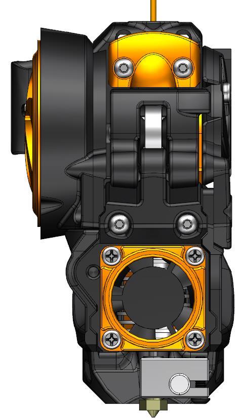
8 12 Install mmfanduct.stl to 2.1-LHlowercover.stl using 2x #2-32 x 3/8 Self Tapping Screws #2-32 x 3/8 screw #2-32 x 3/8 screw mmfanduct.stl 2.1-LH-lowercover.stl Lower Cover Assembly 13 Attach lower cover assembly using 1x #2-32 x 3/8 and 1x #2-32 x 5/16 Self Tapping Screw #2-32 x 5/16 screw #2-32 x 3/8 screw


.")

9 14 Press-fit 2.1-drilltemplate.stl over 94T main gear hub 2.1-drilltemplate.stl Note: Do not place holes on template in front of gear set screw (this ensures you can access set screw with an Allen Key after assembly). 15 Carefully drill holes in gear as shown Drill 3x holes using either a 3/32 or #42 drill bit. Drill hole using either a 9/64 or #28 drill bit.


10 16 Install 50mm shaft onto drive gear and tighten set screw 5mm Dia. Shaft 50mm length Note: Shaft should be flush with outer face of gear. 2.1-gearcover.stl #2-32 x 5/16 screw 17 Attach 2.1-gearcover.stl using 3x #2-32 x 5/16 Self Tapping Screws #2-32 x 5/16 screw #2-32 x 5/16 screw


11 18 Install 94T Main Gear Assembly and MK7 Drive Gear Note: Loosely tighten Mk7 Drive gear, final adjustment and tightening will be made at final extruder assembly. MK7 Drive Gear
 Gearset Version 1.1 Aluminum Gearset Print and use 1.0-spacer.")
12 18a Other Possible Gear Configurations for v2.0 Version 1.0 Acetal (Delrin) Gearset Version 1.1 Aluminum Gearset Print and use 1.0-spacer.stl Use a Stainless Steel M5 Washer


13 19 Press-Fit MR685ZZ Radial Bearing into 2.1-LH-bearingholder.stl LH-bearingholder.stl Note: To keep the bearing true, it is best to use a flat surface and set the bearing down on it. Simply press the bearing holder down over the bearing until it hits the flat surface - ensuring that the bearing does not tilt as it goes into the bearing holder hole. Install Bearing Holder Assembly 21 Install 2.1-washer-M5.stl and 5mm Shaft Collar and tighten set screw. Note: Tightly hold entire extruder gearset together onto extruder when tightening shaft collar set screw. Option: If you don t have the 5mm shaft collar, you can print 2.1-shaftcollar.stl and mount it to the shaft w/ an M3x3mm set screw. 2.1-washer-M5.stl 5mm Shaft Collar


14 22 Install heated M3x4 Knurl Nut into 2.1-LH-decorationcover.stl as shown M3x4 Knurl Nut Note: To melt the knurl nut in place, thread a long M3 screw through the knurl nut as shown. This allows the soldering iron to rest on the knurl nut edge while heating and installing the screw can also be used to control perpendicularity, guiding the knurl nut during installation. 2.1-LH-decorationcover.stl 23 Loosely Install 2.1-LH-decoration-spacer.stl and 2.1-LH-decorationcover.stl using 2x #4-20 x ¾ and 1x #4-20 x ½ Self Tapping Screws. Note: Do not yet fully-tighten self-tapping screws leave them slightly loose to allow cover adjustment in next step. Be sure screws are used in proper places to avoid damage to PTFE tubing 2.1-LH-decorationcover.stl #4-20 x 3/4 Self Tap Screw #4-20 x 3/4 Self Tap Screw 2.1-LH-decoration-spacer.stl #4-20 x 5/8 Self Tap Screw


15 24 Insert 2.1-ilderholder.stl into extruder and fasten it in place with a M3x40mm screw. M3x40 Screw 2.1-idlerholder.stl Note: Fastening the M3x40mm screw in place before tightening the decoration cover helps align system for hot-end installation and removal. 25 Fully tighten 2.1-LH-decorationcover.stl onto extruder by fully tightening self tapping screws from Step #23. Install #2-32 x 5/16 self-tapping screw. After fully-tightening cover, remove M3x40mm screw and 2.1-idlerholder.stl. Fully-tighten 3x screws #2-32 x 5/16 screw


16 26 Install 40x40x15mm Delta Bed Cooling Fan with 4x #4-20 x 3/4 Self Tapping Screws 4x #4-20 x 3/4 Self Tap Screws 40x40x15mm Delta AFB0412SHB cooling fan 27 3x M3x16 motor mount bolts Adjust gear-gear positioning by adjusting motor position and tightening 3x M3x16 motor mount bolts. Adjust motor position Note: The goal in this step is to adjust the motor and ensure the gap between gears is suitable. Once the motor is fully tightened, there should be EVER SO SLIGHT of gap between the two gears and they should rotate freely without binding. If this is not done properly, bound gears could cause the extruder motor to bind up and miss steps. Note: After your first long print, you should slightly re-tighten your motor mount bolts after the motor has set in place.


17 28 Install 2.1-LH-smallgearcover with 2x #2-32 x 5/16 self tapping screws #2-32 x 5/16 self tap screw #2-32 x 5/16 self tap screw 2.1-LH-smallgearcover.stl 29 Install heated M3x4 Knurl Nut into mmfanmount.stl using same method as shown in Step # Attach mmfanmount.stl to 2.1-idlerholder.stl using #2-32 x 3/8 Self Tapping Screw. M3x4 Knurl Nut #2-32 x 3/8 screw 2.1-idlerholder.stl mmfanmount.stl

. E3d-V6 Hot-end Assembly 2.1-30mmvent.stl 33 Attach 2.1-30mmvent-.")


18 x M3 Nuts Press-fit assembled E3D-v6 hot-end into assembly. Install 2x M3 nuts into mmvent.stl. Note: The v2.1 Toranado Extruder accepts genuine E3Dv6 1.75mm Hot-ends, as well as clone versions sold via ebay (clone version with threaded PTFE tube-holder shown). E3d-V6 Hot-end Assembly mmvent.stl 33 Attach mmvent-.stl using 2x M3x30 machine screws and 2x #2-32 x 3/8 Self Tapping Screws M3x30 screw Note: Tighten these 2x selftapping screws snugly, but do not over-tighten - they are in a delicate area on the 30mm vent and you don t want to crack the plastic! M3x30 screw Note: Tighten these 2x machine screws tightly as they are designed to clamp the hot-end in place on the assembly. #2-32 x 3/8 screw #2-32 x 3/8 screw


19 34 Insert 6255zz radial bearing onto 2.1-idler.stl using 25mm long 5mm diameter shafting zz Radial Bearing Attach idler assembly using M3x22 machine screw M3x22 Screw 5mm dia. shaft 25m length 2.1-idler.stl Note: Be sure to apply even pressure when self-threading machine screws. Do not over-tighten, just seat screw snugly. Idler should move freely but not wobble too much when screw is seated properly. 36 Install 30mm cooling fan using 4x #4-20 x ¾ Self-Tapping Screws mmfancoverlownoise.stl 30x30x10mm Cooling Fan 4x #4-20 x 3/4 Self-Tapping Screws Note: Proper 30mm fan wire exit location


20 37 Insert 3x JST Female Connectors into hot-end assembly slot locations Note: The JST connectors come with cut leads making them perfect for connecting your devices. With the JST connectors in place, begin planning and measuring the lengths for trimming the wires and connecting them to your Thermistor, 30mm Cooling Fan and Heater Cartridge. 3x JST Female Connectors I recommend soldering the connections and using heat-shrink tubing over the wiring, and then zip tying them in place in the slot location noted below. Recommended: When routing 30mm fan wires to back of assembly, use super-glue or some other adhesive in this area to isolate 30mm fan wires from heater-block. JST Female Connector Location for Zip Tie Wire-routing channel Notch in plastic captures nub on JST female connector. Wires routed in this area


21 conncover-hotend.stl 2x #2-32 x 3/8 self-tap screws After wiring is routed and connected, install 2.1- conncover-hotend.stl with 2x #2-32 x 3/8 Self Tapping Screws 39 Align Hot-End Assembly with dovetail slots in housing and pressfit into place. Dovetail slots are located on both extruder housing and hot-end assembly.


22 40 Install M3x40 screw and tighten firmly to extruder housing. 41 Install 1.75mm filament. Use filament to properly align MK7 drive gear. Fully tighten drive gear to shaft. MK7 Drive Gear 42 Close idler, mount your v2.1 Toranado to your printer be happy.


23 18a Hot-End Removal Instructions 1. Remove filament and open drive gear access. 2. Remove M3x40mm Hot- End Containment Screw 3. Insert same 40mm screw into jack-nut location and use it to unseat hot-end assembly from connection system in back. 4. Remove Hot-End From Extruder.
24 beautiful.
Assembly Instructions
 Assembly Instructions Note: Prior to assembly, be sure to remove all printing pads from the printed parts and also be sure to sort through and organize all of your hardware before assembly this will help
V4 Premium Kit. Prusa i3 Build Guide
 V4 Premium Kit Prusa i3 Build Guide Hi! Congratulations on your purchase of the DIYElectronics.co.za Prusa I3 kit, the best South African 3D Printer Kit! Hopefully this should serve as complete guide to
Part 7 Assembling the X axis
 Part 7 Assembling the X axis 1 2 The X axis is a key part of the printer, it carries the extruder on a carriage that moves the extruder laterally in the X axis. The x axis itself is moved vertically on
Code Product Qty 1 Top Vertex 3 2 Hot End Housing 1 3 Bottom Vertex 3 4 Print Platform Lock 3 5 End Stop Holder 3 6 Filament Feeder Motor Bracket 1 7
 List of Parts Code Product Qty 1 680mm Extrusion 3 2 Power Supply 1 3 240mm Extrusion 9 4 42mm Nema 17 Stepper Motor 3 5 Slider-Hotend Connecting Rod 6 6 48mm Nema 17 Stepper Motor 1 7 Linear Rail with
3. X-axis assembly. 3. X-axis assembly. Written By: Jakub Dolezal manual.prusa3d.com/ Page 1 of 13
 3. X-axis assembly Written By: Jakub Dolezal 2018 manual.prusa3d.com/ Page 1 of 13 Step 1 Tools necessary for this chapter Needle-nose pliers for zip tie trimming. 2.5mm Allen key for M3 screws 2mm Allen
Titan Aero Assembly. Titan Aero Assembly. Learn to assemble your Titan Aero. Written By: Gabe S e3d-online.dozuki.
 Titan Aero Assembly Learn to assemble your Titan Aero Written By: Gabe S. 2018 e3d-online.dozuki.com/ Page 1 of 26 INTRODUCTION The Titan Aero is a very similar build to a Titan and a V6 put together (which
Kossel Rev B Build Guide V1.0
 Kossel Rev B Build Guide V1.0 1 Table of Contents: Step 1: BASE ASSEMBLY Gathering parts: Building the Corners and Base: Step 2: UPPER ASSEMBLY Building Upper: Step 3: VERTICAL RAIL INSTALLATION Building
Written By: Brook Drumm
 Simple 1401 Assembly For kits produced between 1/15/14-6/1/14. This guide is for kits with the Fan Shroud. Instructions for metal and wood extruder (and bed) included below. Written By: Brook Drumm TOOLS:
Assembly Guide for Printrbot - Simple Maker s Edition 1405
 Assembly Guide for Printrbot - Simple Maker s Edition 1405 Last update: March 2016 Please Note: be careful on the steps that are underlined 1 Contents Tools Needed:... 3 First step: Check components and
Goal: Provide a visual guide of the steps needed to construct a Romscraj Extruder.
 V.0 (0 Jul 202) Document Version & Date: V.0 0 Jul 202 Goal: Provide a visual guide of the steps needed to construct a Romscraj Extruder. Original Authors: Md Noh design of the Romscraj Extruder Special
MINI-LATHE QUICK CHANGE TOOL POST
 MINI-LATHE QUICK CHANGE TOOL POST Cutting and assembly details Machinists should familiarize themselves with the contents of this section before jumping in to the drawings. Many details are described here
AndyMark DART 12.
 AndyMark DART 12 Part Number Description QTY These Parts Are Pre-Assembled by AndyMark am-0031 Bearing, 3/16"ID (R3) 1 am-0209 Bearing, 3/8"ID 1614ZZ 2 am-1028 Screw, #10-32x3/8 Pan Head Philips 8 am-1121
(Assembling Guide supplied by imakr ) with the support of MyMiniFactory.com
 with the support of MyMiniFactory.com") (Assembling Guide supplied by imakr ) with the support of MyMiniFactory.com Summary Congratulations on beginning on your journey into 3D printing with the STARTT 3D printer. In this guide, you will have
(Assembling Guide supplied by imakr ) with the support of MyMiniFactory.com Summary Congratulations on beginning on your journey into 3D printing with the STARTT 3D printer. In this guide, you will have
Assembly Instructions Beta Prusa Standard & Deluxe
 Assembly Instructions Beta Prusa Standard & Deluxe 3D Printer Version 2.6 Date Page 1 / 67 General data about the assembly instructions for an incomplete machine according to appendix VI of the EG machinery
Parts & Tools. O'Cello printing and assembly instructions. o-cello.com
 The O'Cello is a 3D-printable cello developed by Conor O'Kane, which is free to download and print for personal use. This document will show you how to print and assemble your own O'Cello. For the latest
How to change a PTFE tube - Original Prusa i3 MK3/MK2.5
 How to change a PTFE tube - Original Prusa i3 MK3/MK2.5 Written By: Jakub Dolezal 2018 manual.prusa3d.com/ Page 1 of 13 Step 1 Getting the correct PTFE tube This guide will take you through the entire
SatNOGS. SatNOGS Rotator v3 Mechanical Assembly. This is the assembly guide for the third version of the SatNOGS Rotator.
 SatNOGS SatNOGS Rotator v3 Mechanical Assembly This is the assembly guide for the third version of the SatNOGS Rotator. Written By: Pierros Papadeas 2017 satnogs.dozuki.com Page 1 of 19 INTRODUCTION Notes:
Droplit v2 Frame Assembly
 SeeMeCNC Guides Droplit v2 Frame Assembly Droplit v2 Frame Assembly Written By: JJ Johnson 2017 seemecnc.dozuki.com Page 1 of 22 Step 1 Droplit v2 Frame Assembly Locate the Projector Plate, Projector Joining
This manual will aid in the assembly of the FireBall V90 and FireBall X90. The assembly of both machines will be identical, unless specified.
 This manual will aid in the assembly of the FireBall V90 and FireBall X90. The assembly of both machines will be identical, unless specified. Step #1 Lay all parts out to verify quantities. (2) 2 x 25-1/4
Lumber Smith. Assembly Manual. If you are having problems assembling the saw and need assistance, please contact us at:
 Lumber Smith Assembly Manual If you are having problems assembling the saw and need assistance, please contact us at: 804-577-7398 info@lumbersmith.com 1 Step 1 Safety Carefully read the Owners Manual.
TIRE RACK INSTALLATION INSTRUCTIONS Dodge Sprinter
 Aluminess Products Inc 9402 Wheatlands Ct. #A Santee, CA 92071 619-449-9930 TIRE RACK INSTALLATION INSTRUCTIONS 07-11 Dodge Sprinter Please read before beginning Stainless steel hardware may bind together
Assembly Instructions. Beta Prusa DualX 3D Printer
 Assembly Instructions Beta Prusa DualX 3D Printer Version 2.6 Date Page 1 / 72 General data about the assembly instructions for an incomplete machine according to appendix VI of the EG machinery directive
5. Extruder Assembly
 5. Extruder Assembly Guide for the assembly of the Extruder. Written By: Josef Prusa 2017 manual.prusa3d.com Page 1 of 22 Step 1 Get the necessary tools 2.5 and 1.5 mm Allen key Needle-nose pliers Step
Assembly Instructions Beta Prusa Standard & Deluxe
 13/11/12 Assembly Instructions Beta Prusa Standard & Deluxe 3D Printer Version 1.0 Date 13/11/12 Page 1 / 66 General data about the assembly instructions for an incomplete machine according to appendix
Open Source Foam Cutter
 Open Source oam utter 4 axis, cheap, modular N hot wire foam cutter Ver. esc. y ate 0.2 OpenS version R. Lodde 22-10-15 Specifications This machine cuts foam (PS, PP, etc.) by moving a hot wire. The wire
LYMANBOT 3D PRINTER V3 Construction Manual
 LYMANBOT 3D PRINTER V3 Construction Manual Page 1 Read this whole Manual before starting to construct this Printer. User excepts all liability for the use of this Manual and the construction of this Printer.
The Portable Open Source 3D Printer
 http://web.archive.org/web/201502142011/http://www.tantillus.org/build_3.html Page 1 of 12 captures 12 Oct 12 - Feb 15 The Portable Open Source 3D Printer Home Start Case X/Y Axis Extruder Z Axis Electronics
Assemble Instruction of Geeetech Acrylic. Prusa I3 Pro C
 Assemble Instruction of Geeetech Acrylic Prusa I3 Pro C Version 04-11-2016 Safety Instructions Building the printer will require a certain amount of physical dexterity, common sense and a thorough understanding
Assemble Instruction of Geeetech Acrylic Prusa I3. Pro & pro B
 Assemble Instruction of Geeetech Acrylic Prusa I3 Pro & pro B Version 04-11-2016 Safety Instructions Shenzhen GETECH CO.,LTD Building the printer will require a certain amount of physical dexterity, common
Replacing the Reciprocator on an SWF Multi-head.
 Replacing the Reciprocator on an SWF Multi-head. Follow the instructions below to replace the reciprocator in the SWF multi-head machines. The tools required are found in the tool kit that came with the
Delta Rostock mini G2& G2s Building instruction
 Delta Rostock mini G2& G2s Building instruction Safety Instructions ShenZhen GETECH CO.,LTD Building the printer will require a certain amount of physical dexterity, common sense and a thorough understanding
Installing CNC Stepper Motor Mounts On A Sherline Lathe
 Installing CNC Stepper Motor Mounts On A Sherline Lathe P/N 6720 (6725 Metric) 4000/4100/4500/4600 Lathes P/N 6730 (6735 Metric) 4400/4410 Lathe USING THE TEMPLATE BLOCKS TO LOCATE NEW MOUNTING HOLES FOR
Nancy s Knit Knacks LLC 4 Yard Option Upgrade Kit Assembly Instructions and User Manual
 Nancy s Knit Knacks LLC 4 Yard Option Upgrade Kit Assembly Instructions and User Manual Thank you for purchasing our 4 Yard Option (4YO) Upgrade Kit. To install this upgrade you are simply going to assemble
1.75mm Direct Titan Assembly
 1.75mm Direct Titan Assembly Learn how to assemble your Titan for use with 1.75mm filament in a direct configuration. Written By: Gabe S. 2018 e3d-online.dozuki.com/ Page 1 of 20 TOOLS: Hex Wrench, 1.5mm
Installing CNC Stepper Motor Mounts On A Sherline Mill
 Installing CNC Stepper Motor Mounts On A Sherline Mill P/N 6700 (6710 Metric) 5000/5100/5400/5410 Mills P/N 6705 (6715 Metric) 2000/2010 Mills USING THE TEMPLATE BLOCKS TO LOCATE NEW MOUNTING HOLES FOR
INSTALLATION INSTRUCTIONS GRILLE GUARD 09-ON DODGE RAM PART #
 INSTALLATION INSTRUCTIONS GRILLE GUARD 09-ON DODGE RAM PART # PARTS LIST: Qty Description Qty Description 1 Grille Guard 8 12-1.75mm x 35mm Hex Bolts 2 Brackets (for trucks without 22 12mm x 30.1mm OD
Citabria Pro. Aerobatic Parkflyer. by Joel Dirnberger
 Citabria Pro Aerobatic Parkflyer by Joel Dirnberger Revision C: December 21, 2004 Citabria Pro Building Instructions Length: Wingspan: Wing Area: Flying Weight: Wing Loading: Functions: Specifications:
Document version: 1.1. Beagle Build manual
 Document version: 1.1 Beagle Build manual TABLE OF CONTENTS Table of contents...2 About the Beagle...3 Change history...4 Safety warnings...4 Required tools...5 1. Bars & Printed parts examination...6
Woodline USA Woodline Spacer Fence System
 Woodline USA Woodline Spacer Fence System MADE IN THE USA Includes: (1) ¼ Spacer Fence (1) 3/8 Spacer Fence (1) ½ Spacer Fence (1) Hardware Package (1) 3 Piece Brass bar set (2) Setup Blocks Visit Us Online
WorkBee CNC. Mechanical Assembly Instructions - Screw Driven
 WorkBee CNC Mechanical Assembly Instructions - Screw Driven Table of Contents 1.0 Getting Started 2 1.1 About The Kit 3 1.2 Check Product Contents 3 1.3 Tools Required 3 1.4 Notes on Assembly 3 2.0 Assembly
WPS crew Doors Installation instructions
 WPS-132-133 crew Doors Installation instructions ORDER OF INSTALLATION FOR A COMPLETE ENCLOSURE OF A CREW WPS (Weather Protection System) IS AS FOLLOWS: 1. Heater 2. Rear Thresholds - Right Hand & Left
Chain Drive Vise. Installation Instructions. (revised 11/29/2018)
") Chain Drive Vise Installation Instructions (revised 11/29/2018) Lie-Nielsen Chain Drive Vise Instructions Table of Contents page About Your Chain Drive Vise 3 Parts List 4 Exploded Parts Diagram 5 step
Chain Drive Vise Installation Instructions (revised 11/29/2018) Lie-Nielsen Chain Drive Vise Instructions Table of Contents page About Your Chain Drive Vise 3 Parts List 4 Exploded Parts Diagram 5 step
Chain Drive Vise. Installation Instructions. (revised 05/04/2016)
") Chain Drive Vise Installation Instructions (revised 05/04/2016) Lie-Nielsen Chain Drive Vise Instructions Table of Contents page About Your Chain Drive Vise 3 Parts List 4 Exploded Parts Diagram 5 step
Chain Drive Vise Installation Instructions (revised 05/04/2016) Lie-Nielsen Chain Drive Vise Instructions Table of Contents page About Your Chain Drive Vise 3 Parts List 4 Exploded Parts Diagram 5 step
Post-Paint>Fuselage>Interior>Controls>Fit rudder pedals
 Post-Paint>Fuselage>Interior>Controls>Fit rudder pedals Objectives of this task: To fit the rudder pedals and steering links to the aircraft, and fit the rudder cable to the rudder pedals and set the deflection
Ender-3 3D Printer. Instructions for assembly
 Ender-3 3D Printer Instructions for assembly This guide is for the Ender-3 3D printer. Select the correct input voltage to match your local mains (220V or 110V). Because of software/hardware upgrades and
LANDING GEAR. 1. Fit landing gear into slots on bottom of fuselage.
 LANDING GEAR 1. Fit landing gear into slots on bottom of fuselage. 4. Use channel-lock pliers to press blind nuts into position (note: drilled hole should be slightly smaller than shaft of blind nut for
INSTALLATION INSTRUCTIONS GRILLE GUARD RAM 1500 PART # 5058/5058-2
 INSTALLATION INSTRUCTIONS GRILLE GUARD PART # 5058/5058-2 PARTS LIST: Qty Description Qty Description 1 Grille Guard 8 12-1.75mm x 35mm Hex Bolts 2 Upper Frame Mounting s (for trucks without tow hooks
Assemble Instruction of Geeetech Acrylic Prusa I3. pro C
 Assemble Instruction of Geeetech Acrylic Prusa I3 pro C Safety Instructions Shenzhen GETECH CO.,LTD Building the printer will require a certain amount of physical dexterity, common sense and a thorough
CRP700 Benchtop Basic CNC Machine Assembly Instructions. Updated 10/24/2014 SHEET 1 of 24
 CRP700 Benchtop Basic CNC Machine Assembly Instructions Updated 0//0 SHEET of NOTE: This piece of extrusion is mounted wide side up Quick Tip: Lay extrusion on table as shown for easy assembly BASE ASSEMBLY:.
HQ Pole Upgrade Kit for HQ Adjustable Table and HQ QuilTable Assembly Instructions 1
 HQ Pole Upgrade Kit for HQ Adjustable Table and HQ QuilTable Assembly Instructions QF09775 The pole upgrade kit can be used with or without the QF09700 HQ Precison-Glide track upgrade kit. What s Included
Zen Toolworks CNC Carving Machine DIY Kit User Installation Manual
 User Installation Manual Visit Us At: http://www.zentoolworks.com or http://www.zentoolworks.com/zenwiki/mediawiki Contact Us At: zentoolworks@gmail.com 1 P-01, Nema 17 Stepper Motor, 3 P-02, Motor Shaft
The Useless Machine. Parts Only - Build Guide v0001
 TM The Useless Machine Parts Only - Build Guide v0001 For the best outcome, follow each step in order. We recommend reading this guide entirely before you get started. Tools required: One phillips screwdriver,
SR-1.0 Manual, a.doc 11/14/2006 Page 1 of 17
 SR-1.0 Manual, 20061108a.doc 11/14/2006 Page 1 of 17 ASSEMBLY INSTRUCTIONS, MODEL SR-1.0 EXTRUSION HEAD STREAMLINE EXTRUSION, INC. Following is a set of photos and verbal descriptions for assembling the
INVENT3D Printer Kit Disassembly Instructions
 INVENT3D Printer Kit Disassembly Instructions Version 6 AST2 10/26/16 1 I. General Disassembly Instructions Use the case layer drawings to ensure that components are stored in the appropriate location
Before returning this product to the store of purchase
 Before returning this product to the store of purchase Contact Dee Zee if you experience the following problems: Missing Parts Installation Problems/Questions Warranty Questions 1.800.779.2102 Hours of
Name Standard or Description QTY.
 Part List Part Number Name Standard or Description QTY. 1 Base - 1 2 Nut Hexagon Nut ISO - 4032 - M3 19 3 Motor/Encoder Assembly Mabuchi RS-645VA and Encoder 1 1 4 M3x10 Screw ISO 7045 - M3 x 10 2 5 Steel
Installation and Assembly - Universal Articulating Swivel Double-Arm for 42" - 60" Plasma Screens
 Installation and Assembly - Universal Articulating Swivel Double-Arm for 42" - 60" Plasma Screens Models: PLAV 70-UNL, PLAV 70-UNL-S PLAV 70-UNLP, PLAV 70-UNLP-S R This product is UL Listed. It must be
M2 Assembly. M2 Sub-Assemblies mm Belt Sub-Assembly mm Belt Sub-Assembly Spider Sub-Assembly... 4
 M2 Assembly Table of Contents M2 Sub-Assemblies... 3 630mm Belt Sub-Assembly... 3 702mm Belt Sub-Assembly... 3 Spider Sub-Assembly... 4 Idler Bolt Sub-Assembly... 8 Y Motor Sub-Assembly... 9 X Motor Sub-Assembly...
Installation for Full Size Polaris Ranger Crew Doors
 Installation for Full Size Polaris Ranger Crew Doors Order of Installation: Heater Doors Wiper on to Windshield Windshield Top & Back Panel Note: Most of the steps in these instructions need to be repeated
Jet-ski with motor boat engine
 117.178 Tools required: Vice with bending support Wood glue (water resistant) Scissors Ruler Pencil Round file ø2 ø3 ø4 Drills Jigsaw Sandpaper Super glue Please Note The OPITEC range of projects is not
Assembly Instructions: Bencher Skylark
 Assembly Instructions: Bencher Skylark Tools Required: Pop Rivet Tool Tape Measure Hex Wrenches Screwdriver Several Disposable Rags Two Saw Horses Several boxes or bowls to hold fasteners and small parts
Ford Pick Up Rear leaf Spring Kit Installation Instructions
 1948-1956 Ford Pick Up Rear leaf Spring Kit Installation Instructions 1-800-984-6259 www.totalcostinvolved.com Parts 48 inch leaf (2) springs (4) U-bolts 3/8-24 x l 1/4bolts (16) & nuts (2) 1/2-20 x 4
Heacent 3D printer assembly manual. Prusa i3
 Heacent 3D printer assembly manual Prusa i3 Y-axis assembly 1. Y axis motor section: Find the belowing parts bag, Y-axis motor Assembled parts are separated as shown below, note that the motor between
TOYOTA MOTOR EUROPE CA Products Division Tel : Fax :
 TOYOTA MOTOR EUROPE CA Products Division Tel : + 32 2 745 26 77 Fax : + 33 2 745 26 99 Ordering part numbers Comments Part Numbers Wooden floor one hatch PZ449-D3C42-11 one hatch with carpet PZ449-D3C42-01
AM8 Printer A metal frame for your Anet A8 By Pheneeny v1.0 April 20, 2017
 AM8 Printer A metal frame for your Anet A8 By Pheneeny v1.0 April 20, 2017 Please read this entire document before printing parts or building this frame Disclaimer: This guide is for informational purposes
Page 1. SureMotion Quick-Start Guide: LACPACC_QS 1st Edition - Revision A 03/15/16
 R K C T I Repair Kit Product Compatibility Repair Kit # Linear Actuator Assembly # LACPACC-002 LACPACC-003 LACP-16TxxLP5 (0.5-in lead screw pitch) LACP-16TxxL1 (1-in lead screw pitch) C P I R K 4 ea Flanged
0. Disassembly. Disassembly of the MK2 printer and upgrading to the MK2S using the upgrade kit. Written By: Jakub Dolezal
 0. Disassembly Disassembly of the MK2 printer and upgrading to the MK2S using the upgrade kit. Written By: Jakub Dolezal 2018 manual.prusa3d.com/ Page 1 of 12 Step 1 Preparing the printer Ensure the printer
Installation and Assembly - Universal Articulating Swivel Double-Arm for 42" - 60" Plasma Screens
 Installation and Assembly - Universal Articulating Swivel Double-Arm for 42" - 60" Plasma Screens Models: PLAV 70-UNL, PLAV 70-UNL-S PLAV 70-UNLP, PLAV 70-UNLP-S R This product is UL Listed. It must be
Inspiration taken from Reprap Mendel Sketchup Model by Capo: om/3dwarehous e/details? mid=86dc5e3cc ad914839c51e370
 Goal: Provide a visual guide of the steps needed to construct a Prusa Mendel Printer. The instructions contained within are copied verbatim from the reprap.org wiki: http://reprap.org/wiki/prusa as of
Installing the Onyx Heated Bed
 Installing the Onyx Heated Bed This short supplement will guide you through replacing the Phebe I heated bed on your Rostock MAX with the new Onyx heated bed. Your Onyx upgrade kit should include the following
END FRAMES. End frames built using pressure treated 2x4 (1 1/2" x 3 1/2") 36" 34" 7/16" pilot hole. 5 1/2" x 1/2" lag bolt 8" wheel 23"
 36 34 7/16 pilot hole. 5 1/2 x 1/2 lag bolt 8 wheel 23") END FRAMES End frames built using pressure treated 2x4 (1 1/2" x 3 1/2") 23" 17 1/2" (B) (B) Measure from the bottom of your stone to 1" below the lip to get your measurement. 17 1/2"(B) 36" 34" 1/2" flat
END FRAMES End frames built using pressure treated 2x4 (1 1/2" x 3 1/2") 23" 17 1/2" (B) (B) Measure from the bottom of your stone to 1" below the lip to get your measurement. 17 1/2"(B) 36" 34" 1/2" flat
3D PRINTER. Pack 11. Anything you can imagine, you can make! 3D technology is now available for you at home! BUILD YOUR OWN
 BUILD YOUR OWN Pack 11 Anything you can imagine, you can make! 3D PRINTER Compatible with Windows 7 & 8 Mac OS X 3D technology is now available for you at home! BUILD YOUR OWN 3D PRINTER CONTENTS PACK
Assembly Instructions 10 X 10 Aluminum Roof Support
 Assembly Instructions 10 X 10 Aluminum Roof Support Aluminum Roof Support Bolt Package 16-5/16 X 2 ¼ SS Bolt 24-5/16 X 1 SS Bolt 40-5/16 SS Nylon Lock Nuts 16-5/16 SS Flat Washers 28-4 ½ Wood Screws 36-1
Pickup Box Utility Rack Package Installation (Instruction ID: )
") 017 Chevrolet Colorado Pickup - WD (VIN S) Canyon, Colorado Accessory Installation Manual N America Document ID: 3966961 Pickup Box Utility Rack Package Installation (Instruction ID:3144879) Installation
017 Chevrolet Colorado Pickup - WD (VIN S) Canyon, Colorado Accessory Installation Manual N America Document ID: 3966961 Pickup Box Utility Rack Package Installation (Instruction ID:3144879) Installation
INSTALLATION INSTRUCTIONS
 TEL -866-XANATOS INSTALLATION INSTRUCTIONS PART#: 7D5000SS\7D500A GRILL GUARD FOR DODGE SPRINTER 07-09 PARTS LIST: 8 6 Grille Guard Driver/Left Frame Mounting Passenger/Right Frame Mounting Driver/Left
Bearing Overhaul Instructions for: Tallboy (.1) 2009
 2009") Bearing Overhaul Instructions for: Tallboy (.1) 2009 Tools Needed: 7900 Removal Tool 7902 Removal Tool 7900/7902/6902 Press Tool Grease Gun (included with frame) (2) ll/16" or adjustable wrenches 9/16"
Bearing Overhaul Instructions for: Tallboy (.1) 2009 Tools Needed: 7900 Removal Tool 7902 Removal Tool 7900/7902/6902 Press Tool Grease Gun (included with frame) (2) ll/16" or adjustable wrenches 9/16"
INSTALLATION INSTRUCTIONS
 INSTALLATION INSTRUCTIONS TM X-10 Type 1F HIGH SECURITY ELECTRONIC LOCK Table of Contents Introduction... 1 Basic Tools and Materials Needed... 1 Lock Parts for Installation... 1 Installation Kit Contents...
HotEnd. HotEnd docs.imade3d.com/ Page 1 of 19
 HotEnd 2018 docs.imade3d.com/ Page 1 of 19 INTRODUCTION JellyBOX uses a genuine E3D-Lite6 HotEnd with our own heat block upgrade for faster and easier printing. Assembly of the hotend should take a quarter
LU6X-130 Instructions and Parts List (including LU6X Basic) Operating Instructions
 Operating Instructions") LORTONE LU6X-130 Item # 061-092 LU6X Basic Item # 061-090 LU6X-130 Instructions and Parts List (including LU6X Basic) Operating Instructions Introduction The LU6X is one the most versatile pieces of equipment
LORTONE LU6X-130 Item # 061-092 LU6X Basic Item # 061-090 LU6X-130 Instructions and Parts List (including LU6X Basic) Operating Instructions Introduction The LU6X is one the most versatile pieces of equipment
INSTALLATION OF WELLS SUPER QUICK CHUCK LEFT HAND ON RED WING LATHE
 DENTAL, INC. TECHNICAL BULLETIN Q824-022510 5860 FLYNN CREEK ROAD READ ALL INSTRUCTIONS P.O. BOX 106 BEFORE PROCEEDING COMPTCHE, CALIFORNIA, U.S.A. 95427 SAVE THIS FOR FUTURE REFERENCE www.wellsdental.com
Installation Instructions
 Installation Instructions 000964 Revision F Installation Instructions for PIRIT Read this manual fully prior to starting installation. Call American eating Customer ervice with any questions. What you
The Useless Machine. DIY Soldering Edition. Instruction Guide v0004
 The Useless Machine DIY Soldering Edition Instruction Guide v0004 TM For the best outcome, follow each step in order. We recommend reading this guide entirely before you get started. Tools required: Soldering
The Astronomical League
 The Astronomical League www.astroleague.org Library Telescope Modifications Check the collimation with the eyepiece cap provided (the one with the hole in its center) before starting on any modifications.
SE5a Instrument Board part 2 - rev 1.1
 SE5a Instrument Board part 2 - rev 1.1 Fuel (Petrol) Valve This valve uses two circular name plates, eight brass screws, one black plastic base, copper wire and two black plastic risers. You can pick any
ABM International, Inc. Navigator Assembly Manual
 ABM International, Inc. 1 1.0: Parts List Tablet (Qty. 1) Tablet mount (Qty. 1) NOTE: Mount may appear and operate different then image below Control Box (Qty. 1) Motor Power Supply (Qty. 1) 2 X-axis motor
!! " # $ % & '! ( ) * +, -
 * +, -") !! " # $ % & '! ( ) * +, - North Pegasus This carton contains: (1) Instruction package. Response Curves North Creek Cabinet Handbook North Creek Wiring Guide (2) 6 oz. Rolls of Dacron stuffing. (1) Tube
!! " # $ % & '! ( ) * +, - North Pegasus This carton contains: (1) Instruction package. Response Curves North Creek Cabinet Handbook North Creek Wiring Guide (2) 6 oz. Rolls of Dacron stuffing. (1) Tube
Hatchback Wing Riser Kit
 Hatchback Wing Riser Kit 2015-06-11 Thank you for purchasing this PERRIN product for your car! Installation of this product should only be performed by persons experienced with installation of aftermarket
Assembly Instructions 10 X 10 Aluminum Frame Building
 Assembly Instructions 10 X 10 Aluminum Frame Building 27 97 9 8 47 36 74 52 10 10 X 10 Square Building W/ Dome Includes: The Steel Entry Door with a Dead Bolt Lock assembly and Aluminum Door Frame. Metal
3DR ArduCopter Quad-C
 3DR ArduCopter Quad-C 3DR ArduCopter Quad-C Thank you for purchasing a 3DR ArduCopter Quad kit. The 3DR ArduCopter Quad is a stable and supported multi-rotor frame in the ongoing development of the ArduCopter
Geeetech Delta Rostock mini G2 pro / G2s pro Building Instruction
 Geeetech Delta Rostock mini G2 pro / G2s pro Building Instruction (Document version: 04-11, 2016) CONTENT Safety Instructions... 1 Preparation... 2 1 Base Assembly... 3 1.1 Motor holder assembly... 3 1.2
15MM LINEAR MOTION SYSTEM
 222fg 15MM LINEAR MOTION SYSTEM September 20, 2017 15mm Linear Motion System Copyright 2017 REV Robotics, LLC 1 TABLE OF CONTENTS 1 INTRODUCTION... 3 2 ASSEMBLY INSTRUCTIONS... 4 3 How to drive Linear
SAFETY INSTRUCTIONS. Wear protective clothing, including safety glasses and steel toe boots.
 SAFETY INSTRUCTIONS Wear protective clothing, including safety glasses and steel toe boots. DO NOT allow loose clothing or long hair near machine operations. Keep work site and machine clean. Use brush
FUSELAGE CONSTRUCTION
 FUSELAGE CONSTRUCTION Note: prior to building and gluing on the work surface use protective covering on your building surface. (wax paper or clear wrap) Fit the laser cut Fuselage Front and Fuselage Rear
Elimination of Elevator Bounce
 For the Agilent Archon Autosampler Rework Instructions CAUTION This kit is intended for use by Agilent Service personnel only. Elevator Removal 1 Open top cover. 2 Open front lower door. 3 Remove vial
3/8-16 x 3/4 cap screw. 3/8-16 hex nut for above screws. 1/4-20 x 3/4 socket cap screw. 3/16 short arm hex key (not to scale)
") Super Slab Roller 24, 30 and 36 models Worktable Assembly Directions P.O. Box 89 Cheney, WA 99004 USA 509.235.9200/800.23.7896 Fax: 509.235.9203 www.northstarequipment.com Revised September, 2006. All
Super Slab Roller 24, 30 and 36 models Worktable Assembly Directions P.O. Box 89 Cheney, WA 99004 USA 509.235.9200/800.23.7896 Fax: 509.235.9203 www.northstarequipment.com Revised September, 2006. All
(W) INSTALLATION INSTRUCTIONS 3" ROUND & 4" OVAL SIDEBAR (90-DEG BENT END) DODGE RAM 1500 QUAD CAB PART #DZ /DZ /DZ /DZ
 INSTALLATION INSTRUCTIONS 3 ROUND & 4 OVAL SIDEBAR (90-DEG BENT END) DODGE RAM 1500 QUAD CAB PART #DZ /DZ /DZ /DZ") (W) INSTALLATION INSTRUCTIONS 3" ROUND & 4" OVAL SIDEBAR (90-DEG BENT END) PART #DZ 372231/DZ 372233/DZ 372237/DZ 372239 PARTS LIST: 3" ROUND & 4" OVAL SIDEBAR (90-DEG BENT END) Qty Description Qty Description
(W) INSTALLATION INSTRUCTIONS 3" ROUND & 4" OVAL SIDEBAR (90-DEG BENT END) PART #DZ 372231/DZ 372233/DZ 372237/DZ 372239 PARTS LIST: 3" ROUND & 4" OVAL SIDEBAR (90-DEG BENT END) Qty Description Qty Description
INSTALLATION INSTRUCTIONS 3 BULL BAR 99-04, 04 "HERITAGE" F-150/250LD 2WD, 97-04, 04 "HERITAGE" 4WD WD EXPEDITION/ WD EXPEDITION PART
 INSTALLATION INSTRUCTIONS 3 BULL BAR PART #B-F1971;B-F2971 PARTS LIST: 1 Bull Bar 2 12-1.75mm x 130mm x 40mm Hex Bolts 1 Driver/Left Mounting Bracket 4 12-1.75mm x 35mm Hex Bolts 1 Passenger/Right Mounting
RangerWare Fiberglass Door System Installation Instructions P/N
 Page 1 of 9 RangerWare Fiberglass Door System Installation Instructions P/N 2878016 ORDER OF INSTALLATION Note: To assure proper order, read all Accessory Installation Instructions before beginning. 1.
INSTALLATION INSTRUCTIONS DODGE RAM 2 & 4WD 1500 PART # P5058
 INSTALLATION INSTRUCTIONS 2009-13 DODGE RAM 2 & 4WD 1500 PART # P5058 PARTS LIST: Qty Description Qty Description 1 Grille Guard 12 12-1.75mm Hex Nuts 2 Upper Frame Mounting s (for trucks without tow hooks
Midwest RDH Handpiece Repair Procedure
 Midwest RDH Handpiece Repair Procedure The Midwest RDH handpiece is fairly common and is used by hygienists to clean teeth. The most common problems for this handpiece include a bad prophy head or a dirty