Welcome! Table of Contents
|
|
|
- Martin West
- 5 years ago
- Views:
Transcription
1 Welcome! The folks at Random Idea Generator Shop would like to thank you for purchasing our 3D printer kit. We are dedicated to providing an easy to build kit with customizable options to meet your requirements. If you have any questions during our build, please feel free to send us an . Table of Contents Welcome! Table of Contents Build your own desktop 3D printer Tools you will need Bill of Materials Assembly Instructions Electronics Wire it all up!: Calibration Print your first Thing! Resources on the internet Support Glossary of Terms and Components 1

2 Build your own desktop 3D printer This is a kit containing all materials and software to build and operate a 3D Printer. The printer is a Graber i3 - with certain modifications, based on the Prusa i3, with nearly all of the parts being laser cut. 2
3 Tools you will need Screw Driver Wrench or pliers (5/16 and 1/2") Bill of Materials Included in the kit you will find everything you need to build the basic kit: Laser cut Frame Includes nuts and bolts 5x stepper motors - 40 N-cm (56 oz-in) RAMPS 1.4 Controller includes: Arduino Mega 2560 R3, 4x Stepper drivers w/ heat sinks. 12V 30A Power Supply 2x belts and pullies 5x 608zz bearings 10x LM8UU linear bearings Extruder hot end Extruder cold end 3x Endstops with wires 5x Springs for extruder and bed 2x 5mm x 11.5 Threaded rodw/ nuts 6x 8mm smooth rod. 2x 12.5 (Z), 2x 13.5 (Y), 2x (X) Heated Build Platform, 8 x 8 glass not included Nuts and bolts - #6-32 (41x 3/4, 6x 1/2, 2x 1, 4x 1-1/4, 8x 1-3/4 ), M3 (20x 10mm, 4x 25mm, 4x 20mm), M4 (3x 12mm) Software and firmware Repetier is loaded on the controller and the host software is included on disc, but can be downloaded from Repetier.com. 3
 to left and right Z- axis stepper motor mounts (G). Chamfered corner will be the front outside corner.")
 6-32 x 3/4\" bolts (2) 6-32 nuts <insert better photo> 3. Attach the left and right uprights (B) to the base.")
4 Assembly Instructions The frame is designed to go together relatively quickly, but it s main benefits are its rigidity and ease of calibration. Assemble the Z motor mounts: 1. Attach brackets (H) to left and right Z- axis stepper motor mounts (G). Chamfered corner will be the front outside corner. Requires: (4) 6-32 x 3/4" bolts (4) 6-32 nuts <insert photo> 2. Attach the Z motor mounts to the main upright (F). Requires: (2) 6-32 x 3/4" bolts (2) 6-32 nuts <insert better photo> 3. Attach the left and right uprights (B) to the base. (A) Orient the base such that the two square holes near the middle are facing the front, and the low portions of the uprights are facing front. Requires: (6) 6-32 x 3/4" bolts (6) 6-32 nuts 4
 into the square hole on the rear of the base Requires: (2) 6-32 x 1/2\" bolts (2) 6-32 washers <attach photo showing how attached> 5. Attach front (D) and rear (E) faces.")
5 <insert photo of attached base and sides> 4. Put the Y-axis motor mount (K) into the square hole on the rear of the base Requires: (2) 6-32 x 1/2" bolts (2) 6-32 washers <attach photo showing how attached> 5. Attach front (D) and rear (E) faces. Secure idler and motor mount brackets to front and rear faces. Requires: (8) 6-32 x 3/4" bolts (3) 6-32 x 1/2" bolts (3) 6-32 washers (11) 6-32 nuts 6. Slide the main upright into position and secure to the left and right uprights. Requires: (6) 6-32 x 3/4" bolts (6) 6-32 nuts 5


6 7. Insert 2 threaded rod with 608zz bearing into the idler brackets and secure with 2 nuts each side as jam nuts. Don t over tighten, make sure the bearing is free to turn. This is a good time to put one of the GT2 belts around the bearing as you insert it. It will make getting the belt in easier, and it can also help you align the bearing to the threaded rod. 8. Attach Y-axis rod stops to front and back faces. Use one bolt in the bottom hole. Requires: (4) 6-32 x 3/4" bolts (4) 6-32 nuts (2) 13-1/2" M8 smooth rods (1) LM8UU bearing on the right (2) LM8UU bearings on the left (4) Zipties to secure rods 6
 M3 x 10mm bolts Assemble Y-axis and print bed: 1. Attach Y-axis endstop to back right side M8 smooth rod.")
. Requires: (1) 6-32 x 1 bolt (1) 6-32 nuts <insert photo> 3.")
7 9. Install Z and Y-axis motors. The Z motor with the longest lead should be on the right. Requires: (11) M3 x 10mm bolts Assemble Y-axis and print bed: 1. Attach Y-axis endstop to back right side M8 smooth rod. Requires: (1) 6-32 x 3/4" bolt (2) 6-32 x 1/2" bolts (3) 6-32 nuts (1) endstop with wire <insert photo> 2. Attach Y-axis enstop flag to Y-carriage base (M). Requires: (1) 6-32 x 1 bolt (1) 6-32 nuts <insert photo> 3. Attach the two belt brackets (P) to the Y-carriage base. Insert belt attachment bolts. Requires: (2) 6-32 x 3/4" bolts 7

 and resistor to board for power indicator. 8.")
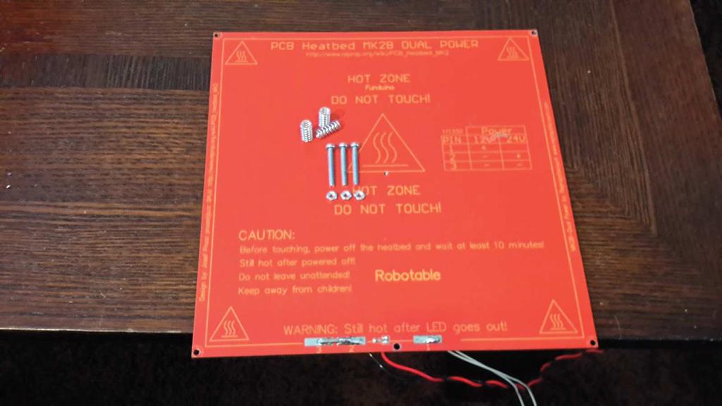
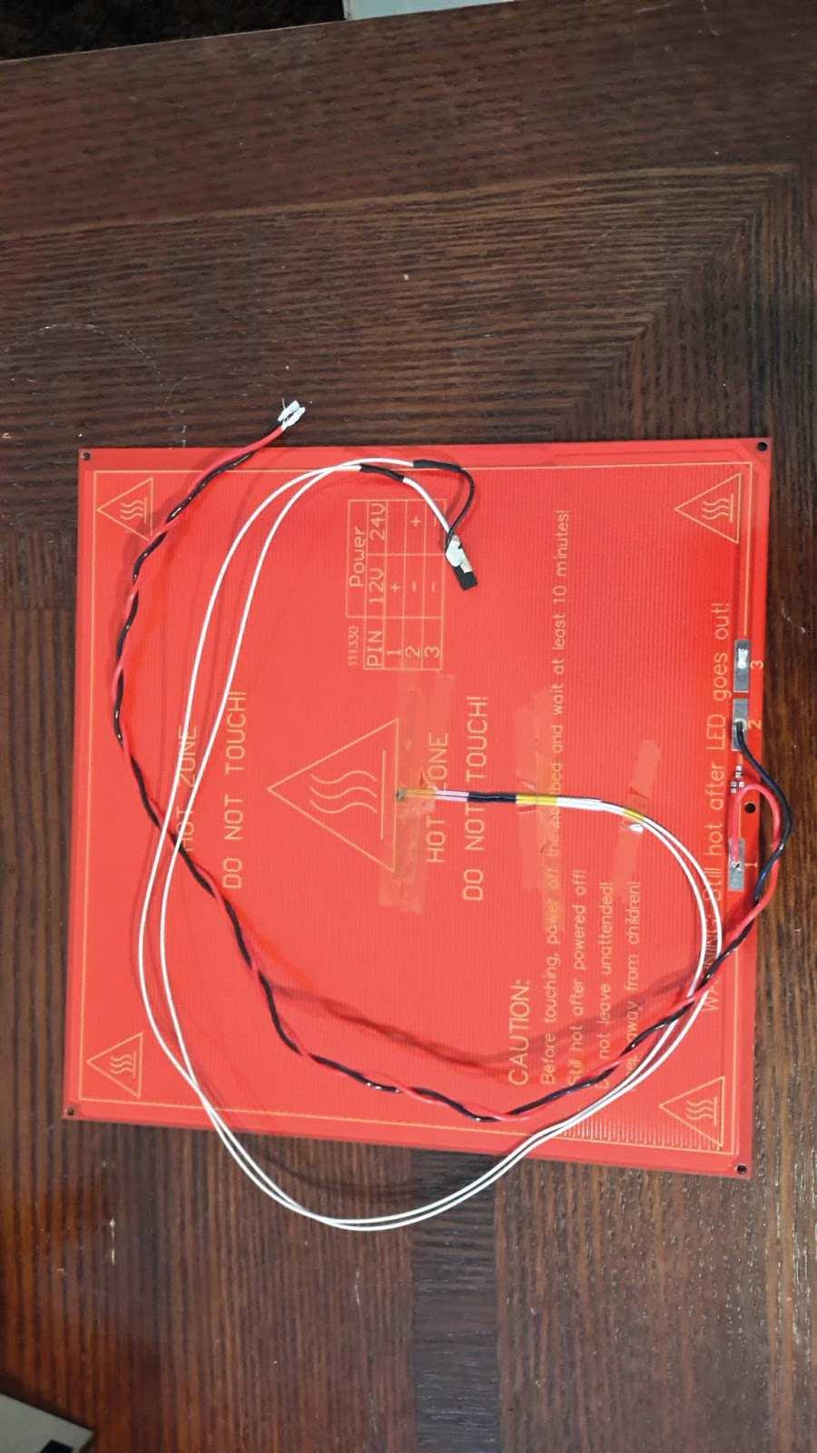
8 (2) 6-32 x 1 Bolts (4) 6-32 nuts. Attach to linear bearings using zip ties. 5. Insert thermistor into Heated Build Platform center hole and secure kapton tape. 6. Solder 18 wire to HBP, connecting the negative lead to both pads 2 and Solder LED(s) and resistor to board for power indicator. 8. Attach the heated build platform (HBP) to the Y-carriage base (3) M3-25 bolts (3) M3 nuts (3) springs inserted between the bed and the carriage 9. Place an 8 x 8 piece of glass on the HBP attach with (4) mini clips.. 8
9

10 I typically mount mine with the LED in the rear as it provides better movement for the wires. I also ziptie the wires to the back right hole on the carriage. Assemble X-axis Motor Mount: 1. Place the X-axis motor mount (Y) on a level surface. 10

")
11 2. Insert two the rod spacers (Q), large tab down, in the two large slots near the middle.. Insert X-axis motor bearing plate (X) into the X-motor mount sides (Z). 11
. 5.")

.")
12 . Insert the X-motor mount sides (Z) onto the.motor mount (Y). 5. Place (2) LM8UU bearings in slot and Insert (2) 6-32 x 3/4" bolts.. Insert Z-axis nut and threaded rod into outside facing recess and cover with (AA). I recommend using hot glue or something similar to secure the nut in place so it doesn t wiggle in the nut capture. 12

 on a")
, large")
13 7. Install X-axis motor mount top (W) and secure with 1-3/4 bolts. Assemble X-axis Idler: 1. Place the Y-axis idler base (T) on a level surface.. Insert two the rod spacers (Q), large tab down, in the two large slots near the middle. 13
 into the X-idler")
")
14 . Insert X-axis idler bearing plate (S) into the X-idler sides (U).. Insert the X-idler sides (U) onto the Idler mount (T). 14


15 . Insert two LM8UU bearings in slot.. Insert 3/8" x 1-3/4" threaded rod into idler cover and secure with a nut each side. Leave enough so the rod will be flush to the back of the idler assembly. 15
 and attach front plate (R)")

16 . Place (1) 608zz bearing between the back(t) and the bearing plate (S) and attach front plate (R) with (4) 6-32 X 1-3/4" bolts.. Insert Z-axis nut into outside facing recess and cover with (V). 16

.")
17 . Install X-axis idler top (R) and secure with 1-3/4" bolts. Assemble the X-carriage: 1. Insert (3) 6-32 x 1 bolts into the top and side holes of the X-carriage base (N1). The shorter slot on N1 will be up. 17
.. Insert three LM8UU bearings. 4.")
. 2. (1) LM8UU bearing will be the top, (2) bearings on the bottom. 3.")
18 . Attach Extruder Body to (N1) using (2) 6-32 x 1-3/4" bolts. I ve found it s better to put the bolts in from the back so the nuts are on the face of the extruder body (not as shown in the image below).. Insert three LM8UU bearings. 4. Install X-carriage back(n2) and secure with 1 bolts. The top bolt s nut can be secured with a wrench as long as you place a little tension on the bolt to keep it from turning. Assemble X and Z-axis: 1. Slide smooth rod into X-carriage bearings (X-carriage not shown for clarity). 2. (1) LM8UU bearing will be the top, (2) bearings on the bottom. 3. Insert X-carriage assembly into X-idler assembly. Idler will be on the right. 4. Insert X-carriage assembly into X-motor mount assembly. Motor will be on left. 5. Slide 12.5 smooth rod into X-axis motor mount bearings and X-axis idler bearings. 6. Insert M5 x 11.5 threaded rod into the captured nuts on the motor mount and idler assemblies. 18

 M3 x 10mm bolts. 11.")
19 . Insert assembly into the rod holes on Z-motor mounts (G).. Attach left and right Z-axis rod holders (I). 9. Using 1 length of tubing attach the threaded rod to Z-axis motors. I recommend some sort of adhesive to prevent the threads from backing out, though I ve never experienced this. 10. Mount X-axis motor with (4) M3 x 10mm bolts. 11. Attach X and Z endstops using (2) 6-32 x 1/2" bolts and (2) 6-32 x 3/4" bolts. <attach photos> 19


20 Extruder Cold End assembly: 1. Insert (2) 608zz bearings into recesses on extruder body. 2. Using 3/8 x 3/4" threaded rod place 608zz bearing into extruder idler. 3. mount idler to extruder body.. Mount extruder motor with (3) M3 x 10mm bolts, keep loose. 5. Attach extruder idler with (1) M3 x 25mm bolt. 6. Insert hobbed bolt into big gear. 7. Insert M3 nut and set screw into small gear. 8. Insert hobbed bolt and big gear into body and slide small gear into place on motor shaft. Use washers on hobbed bolt between extruder body and big gear to get correct spacing for good 20

 6-32 x 2 bolts with springs and washers through the top of the idler assembly to nuts in the extruder body.")
21 alignment of the hobbed area with the filament feed hole. Use (2) jam nuts on the back to secure hobbed bolt in place.. Tighten set screw on small gear to motor shaft. 10. Make sure the gears have good contact and tighten motor. 11. Insert (2) 6-32 nuts into nut capture slots on top of extruder body. 12. Use (2) 6-32 x 2 bolts with springs and washers through the top of the idler assembly to nuts in the extruder body. <insert photo> Attach belts: 1. Attach (1) GT2 pulley to Y-motor and tighten set screws. 2. Make sure Y-motor is loose in the mount to allow tightening later. 1


22 3. Attach one end of the belt to the Y-carriage bolt on (P) by folding over and zip tying in place. Make the excess as small as possible to allow as much movement as possible. 4. Run Y-axis belt through idler, around Y-motor pulley and back to Y-carriage, if not already.. Attach end of belt as above. Make sure it s taught.. Tighten belt by adjusting Y-motor before tightening motor mount bolts. 7. X-carriage is similar to above. Electronics Assemble Control Board 1. Attach RAMPS 1.4 control board to Arduino Mega 2. Install DRV8825 Stepper Drivers. The chip will be away from the power connectors. You can also look at the bottom of the driver to see the pin assignments and align them appropriately to the board. 3. Attach heatsinks using heatsink paste or adhesive. 4. Attach to left upright with (2) M3 x 25mm bolts. I prefer on in the top right and another in the bottom left. 22

23 nstall drivers, software and firmware: 1. Install Arduino software and USB drivers. 2. Install Repetier Host. This includes Slic3r, Skeinforge, and Cura Engine. 3. The Arduino already has the latest firmware loaded. 4. Connect the Control Board to your PC and verify it is recognized. 5. Open Repetier Host and connect to the Control Board and verify it is communicating. You can wait until you re finished wiring, but it s always good to verify everything is communicating. *If your status line says N Commands waiting you re having communications issues and you re not communicating with the Arduino. Assemble RAMPS board fan 1. Attach (1) 40mm fan to the fan mount peices using (4) M3 x 20mm bolts. Assemble the Extruder Hotend: Your hotend should be assembled with the exception of adding the fan and fan mount. 1. Attach fan to motor mount using (2) M3 x 20mm bolts 2. Attach the fan housing to the Aluminum body of the hot end. Secure with zip tie. 3. Insert hotend into base of extruder body and hold in place with (2) M3 x 20mm bolts. 4. Run hotend wireing along the inside of the extruder motor and combine wiring, secure with zip tie. Use wire wrap to make it look nice. Attach Power Supply 1. Screw onto right side with (3) M4 x 12mm bolts, wire connections on the bottom. 23


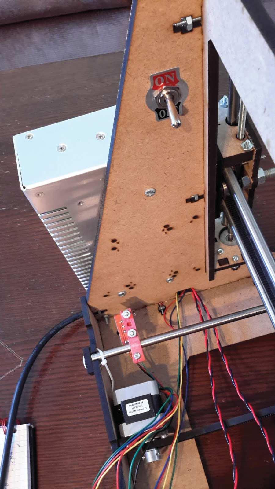
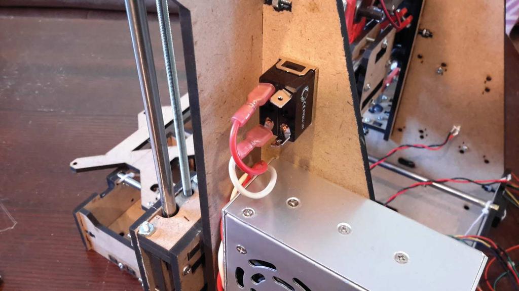
24 . Attach (2) positive and (2) negative wires to the output screw terminals. 3. Attach power cable to input. White is typical Line (L), Black is typically Neutral (N), Green or Black with Green stripe is typically Ground.. Optionally: buy a 125V 20A switch and place it in series with the Neutral. Mount it above the power supply. Needs (2) peices of wiring 18 long with connectors and solder. 24
25 25

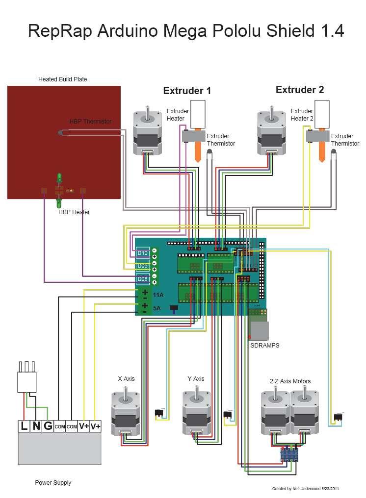
26 Wire it all up!: If the markings on RAMPS board are not clear, use the following images for reference. Polarity is very important in all cases except thermistors and the hotend heating cartridge. 6
27 7
28 1. Plug in Z motors, red wires at the top. 2. Plug in Hotend Thermistor to T0, polarity not important. 3. Plug in HBP Thermistor to T1, polarity not important 4. Plug in Y motor, red wire on top. 5. Plug in X motor, red wire on bottom. 6. plug in X-axis Min endstop, bottom most pins in endstop area, red wire on right. 7. Plug in Y-axis endstop, 3rd set of pins from bottom. 8. Plug in Z-axis endstop, 2nd set of pins from top. 9. Plug in Extruder motor, red wire on bottom. 10. Screw Extruder heater into D10 terminals, polarity not important. 11. Screw HBP wires into D8 terminals. Check polarity. 12. Screw Hotend Fan and 11A power supply wring into screw terminals. Check polarity. 13. Screw RAMPS Fan and 5A power supply wiring into screw terminals. Check polarity. 14. Wrap wiring. Calibration Verify that you are not driving too much voltage to your steppers. 1. Turn on, or plug in, your power supply. 2. Using a multimeter, measure the voltage from the center of the small trim potentiometer and ground. This should be set to approximately volts. 3. Turn clockwise to reduce the voltage. Connect to Repetier Host and check endstop functionality. 1. Once connected to Repetier Host, go to the Manual tab and enter M119 in the G-Code text box. 2. All endstops should report L. Adjust Endstop placement 1. X and Y endstops should be positioned such that the hotend s nozzle is in the front left corner when Homed. 2. Set Z endstop so the nozzle homes to slightly above the HBP on the left side. a. When finished bed leveling the Z endstop should be set so that the nozzle is close enough to the build platform that you can just slide a piece of paper between them with a slight bit of resistance. Bed leveling 1. Adjust the (3) bolts holding the HBP to the carriage so they are of equal height. 2. Set the nozzle at Home X and about 100mm Y. This will be on the right side about halfway up the Y-axis. 3. Adjust Z endstop so you can just feel it touching a piece paper between the nozzle and HBP. 4. Set the nozzle to X maximum, about mm, so the nozzle is all the way to the right side of the platform. 5. Adjust either the HBP screws or the right side Z-axis threaded rod so that it just touches the paper. 6. Do this several times until it is perfectly even from one side to the other. 7. Place nozzle at the center of the build platform and move it along the Y-axis and perform the same adjustments, turning the single center HBP screw and adjusting the endstop height as needed to level the bed from front to back. 28
29 8. Jog the nozzle around the HBP and make sure you feel the same amount of resistance on the piece of paper in every part of the bed. Print your first Thing! This is where you really begin to learn about fine tuning your printer to meet your needs. 1. Load the calibration cube in Repetier host. 2. Go to the Slicer tab and select Cura Engine (recommended) 3. Typical settings for: a. PLA are degrees for the extruder, and 55 for the HBP. b. ABS are degrees for the extruder, and 110 for the HBP. c. Play with these numbers as preferences vary. 4. Slice and Print. 5. Tweak Resources on the internet There is a fantastic support forum and wikis on RepRap.org to help you with tuning your 3D printer. There are many techniques and philosophies on the best approach to achieving great prints, it s up to you to decide what works best for you. If you are looking for places to find things to print that others have already created, try Thingiverse.com. There are many other repositories for objects, this is one of the more popular ones. Support For assistance or support you may reach us at info@randomideagenerator.com Glossary of Terms and Components This is a list of terms and definitions you may come across in your learning about 3D printers, this list is by no means comprehensive, but is meant to provide you with some basic information on common terms. RepRap - Open Source self-replicating machine. Uses FDM, fused deposition modeling. RepStrap - Similar to RepRap except mainly non-printable, such as this kit. Vitamins - Anything not printed or specifically generated, i.e. nuts and bolts, bearings, rod, and threaded rod. 3 Axis s of motion - X, Y, and Z. This is a standard Cartesian coordinate system. X axis is left and right movement 29
30 Y axis is forward and back movement Z axis is up and down movement Stepper Motors are motors with a specified number of steps per revolution that the controller uses to precisely track and position the print head. Extruder - Delivers the plastic to the print bed. Consists of a cold and hot end. Cold end - Has a stepper and toothed shaft to push plastic to the hot end. Hot end - Has an orifice that once the heating element heats the plastic in a reservoir it is then squeezed out of and onto the print bed. Build platform - The area that the plastic is extruded onto creating your model. Can be heated or not. Heated beds are best used with ABS to prevent the model from lifting or warping. Types of plastic - PLA (Polylactic acid) and ABS ( Acrylonitrile butadiene styrene) are the two most commonly used, but there are many more materials available and more coming to market. PLA - Is a biodegradable plastic derived from corn starch. It has a lower melting point, is harder and more brittle. It s not UV resistant and will warp in warm temperatures. It s very forgiving for the beginning 3D enthusiast. ABS - Is a petroleum based plastic and is very widely used. It has a higher melting point, is more durable as it s not as brittle. The parts tend to be more resilient. Models: STL files - any 3D model you create must be exported or converted to an STL file. CAD/CAM Software - There are many modeling programs available ranging from free to many thousands of dollars. Here is a short list of examples: OpenSCAD - Freeware, is a code based 3D modeling software. SketchUp - Freeware, with paid versions available, is a visual 3D modeling software that is widely used and supported. Blender - Freeware, used for many 3D applications including animation. FreeCAD - Freeware, I don t know much about this. 30
31 123D Design - A free Autodesk product, very limited in capabilities compared to thier other products. Is specifically aimed at the maker community, included in a suite of 123D programs. AutoCAD - Autodesk product, expensive but very robust modeling software. Does not do organic forms easily. 3DS Max - Autodesk product, aimed more at animation and 3D rendering, it s very complex with many options. Modeling can be difficult at first but results are very good. Solidworks - A mechanical engineering software that can be used to build a virtual mechanism to test functionality before exporting individual pieces for printing. 3D Scanning 123D Catch - Part of the Autodesk 123D suite. Takes a series of photos and stitches them together to generate a model you can print. Xbox Kinect - Uses stereoscopic imaging to scan an object. Other similar tools are on the market. Other forms of scanning include some laser and camera based options that can be DIY d or purchased. Slicers - Takes your STL file and generates G-code, for your control software to send to your printer. There are many slicers available. Slic3r - Open Source, is simplified, but does offer many advanced options. Skeinforge - Open Source, lots of variables, some can be obscure. Cura Open Source but maintained by Ultimaker. Printer Control - Includes host software and the firmware that is loaded on your microcontroller. Allows you to manually control your printer as well as sending the G-code commands. Host software Repetier - a package including both firmware, host software, it also has Slic3r, Skeinforge, and Cura embedded. Pronterface - Is host software and can speak to many different firmwares. Cura is also offered as a package but can be used as individual components. Firmware Loaded onto your microcontroller this receives and interprets the commands from the 31
32 print control, or host, software and sends it to the various components of your 3d printer. Repetier Teacup Marlin Sprinter Microcontrollers Programmed with the firmware it receives commands and then controls movement and temperature through the use of G-code. G-Code is used to send a command or a query to the microcontroller. Information is either movement, temperature, or fan control. The host software will also query the temperature inputs to precisely control the temperature of the extruder and the heated bed. 32
Kossel Rev B Build Guide V1.0
 Kossel Rev B Build Guide V1.0 1 Table of Contents: Step 1: BASE ASSEMBLY Gathering parts: Building the Corners and Base: Step 2: UPPER ASSEMBLY Building Upper: Step 3: VERTICAL RAIL INSTALLATION Building
Assembly Guide for Printrbot - Simple Maker s Edition 1405
 Assembly Guide for Printrbot - Simple Maker s Edition 1405 Last update: March 2016 Please Note: be careful on the steps that are underlined 1 Contents Tools Needed:... 3 First step: Check components and
V4 Premium Kit. Prusa i3 Build Guide
 V4 Premium Kit Prusa i3 Build Guide Hi! Congratulations on your purchase of the DIYElectronics.co.za Prusa I3 kit, the best South African 3D Printer Kit! Hopefully this should serve as complete guide to
Written By: Brook Drumm
 Simple 1401 Assembly For kits produced between 1/15/14-6/1/14. This guide is for kits with the Fan Shroud. Instructions for metal and wood extruder (and bed) included below. Written By: Brook Drumm TOOLS:
5. Extruder Assembly
 5. Extruder Assembly Guide for the assembly of the Extruder. Written By: Josef Prusa 2017 manual.prusa3d.com Page 1 of 22 Step 1 Get the necessary tools 2.5 and 1.5 mm Allen key Needle-nose pliers Step
BIGBOT ASSEMBLY INSTRUCTIONS. 1/18/2017 V0.5
 BIGBOT ASSEMBLY INSTRUCTIONS www.bigbot-3d.com 1/18/2017 V0.5 FOREWORD: PLEASE TAKE CARE WHEN HANDLING THE GANTRY. THE ASSEMBLY SHOULD BE HANDLED ONLY BY THE ALUMINUM FRAME, AND AVOID TOUCHING OR LIFTING
Delta Rostock mini G2& G2s Building instruction
 Delta Rostock mini G2& G2s Building instruction Safety Instructions ShenZhen GETECH CO.,LTD Building the printer will require a certain amount of physical dexterity, common sense and a thorough understanding
Assemble Instruction of Geeetech Acrylic Prusa I3. pro C
 Assemble Instruction of Geeetech Acrylic Prusa I3 pro C Safety Instructions Shenzhen GETECH CO.,LTD Building the printer will require a certain amount of physical dexterity, common sense and a thorough
Part 7 Assembling the X axis
 Part 7 Assembling the X axis 1 2 The X axis is a key part of the printer, it carries the extruder on a carriage that moves the extruder laterally in the X axis. The x axis itself is moved vertically on
AM8 Printer A metal frame for your Anet A8 By Pheneeny v1.0 April 20, 2017
 AM8 Printer A metal frame for your Anet A8 By Pheneeny v1.0 April 20, 2017 Please read this entire document before printing parts or building this frame Disclaimer: This guide is for informational purposes
(Assembling Guide supplied by imakr ) with the support of MyMiniFactory.com
 with the support of MyMiniFactory.com") (Assembling Guide supplied by imakr ) with the support of MyMiniFactory.com Summary Congratulations on beginning on your journey into 3D printing with the STARTT 3D printer. In this guide, you will have
(Assembling Guide supplied by imakr ) with the support of MyMiniFactory.com Summary Congratulations on beginning on your journey into 3D printing with the STARTT 3D printer. In this guide, you will have
Assemble Instruction of Geeetech Acrylic. Prusa I3 Pro C
 Assemble Instruction of Geeetech Acrylic Prusa I3 Pro C Version 04-11-2016 Safety Instructions Building the printer will require a certain amount of physical dexterity, common sense and a thorough understanding
Assemble Instruction of Geeetech Acrylic Prusa I3. Pro & pro B
 Assemble Instruction of Geeetech Acrylic Prusa I3 Pro & pro B Version 04-11-2016 Safety Instructions Shenzhen GETECH CO.,LTD Building the printer will require a certain amount of physical dexterity, common
Assembly Instructions Beta Prusa Standard & Deluxe
 Assembly Instructions Beta Prusa Standard & Deluxe 3D Printer Version 2.6 Date Page 1 / 67 General data about the assembly instructions for an incomplete machine according to appendix VI of the EG machinery
The Portable Open Source 3D Printer
 http://web.archive.org/web/201502142011/http://www.tantillus.org/build_3.html Page 1 of 12 captures 12 Oct 12 - Feb 15 The Portable Open Source 3D Printer Home Start Case X/Y Axis Extruder Z Axis Electronics
Assembly Instructions. Beta Prusa DualX 3D Printer
 Assembly Instructions Beta Prusa DualX 3D Printer Version 2.6 Date Page 1 / 72 General data about the assembly instructions for an incomplete machine according to appendix VI of the EG machinery directive
4. Z-axis assembly. 4. Z-axis assembly. Written By: Josef Prusa manual.prusa3d.com Page 1 of 18
 4. Z-axis assembly Written By: Josef Prusa 2017 manual.prusa3d.com Page 1 of 18 Step 1 Get the necessary tools 13/17mm spanners 3.6mm flathead screwdriver Needle-nose pliers 2.5 and 1.5mm Allen key Step
TL4100 Top 5 Build Tips
 TL4100 Top 5 Build Tips 1: Top Plate When assembling the top plate, align the top of the top plate brackets with the top of the rods. This can be done by placing a hard flat object (such as a ruler) on
M2 Assembly. M2 Sub-Assemblies mm Belt Sub-Assembly mm Belt Sub-Assembly Spider Sub-Assembly... 4
 M2 Assembly Table of Contents M2 Sub-Assemblies... 3 630mm Belt Sub-Assembly... 3 702mm Belt Sub-Assembly... 3 Spider Sub-Assembly... 4 Idler Bolt Sub-Assembly... 8 Y Motor Sub-Assembly... 9 X Motor Sub-Assembly...
Document version: 1.1. Beagle Build manual
 Document version: 1.1 Beagle Build manual TABLE OF CONTENTS Table of contents...2 About the Beagle...3 Change history...4 Safety warnings...4 Required tools...5 1. Bars & Printed parts examination...6
LYMANBOT 3D PRINTER V3 Construction Manual
 LYMANBOT 3D PRINTER V3 Construction Manual Page 1 Read this whole Manual before starting to construct this Printer. User excepts all liability for the use of this Manual and the construction of this Printer.
Geeetech Delta Rostock mini G2 pro / G2s pro Building Instruction
 Geeetech Delta Rostock mini G2 pro / G2s pro Building Instruction (Document version: 04-11, 2016) CONTENT Safety Instructions... 1 Preparation... 2 1 Base Assembly... 3 1.1 Motor holder assembly... 3 1.2
Printrbot Simple (Model 1403) Rev F Printrboard
 Rev F Printrboard") Printrbot Simple (Model 1403) Rev F Printrboard Printrbot Simple is currently shipping with the Rev F Printrboard. Check which rev Printrboard your Simple kit includes and use the corresponding instructions.
Printrbot Simple (Model 1403) Rev F Printrboard Printrbot Simple is currently shipping with the Rev F Printrboard. Check which rev Printrboard your Simple kit includes and use the corresponding instructions.
Assembly Instructions Beta Prusa Standard & Deluxe
 13/11/12 Assembly Instructions Beta Prusa Standard & Deluxe 3D Printer Version 1.0 Date 13/11/12 Page 1 / 66 General data about the assembly instructions for an incomplete machine according to appendix
3. X-axis assembly. 3. X-axis assembly. Written By: Jakub Dolezal manual.prusa3d.com/ Page 1 of 13
 3. X-axis assembly Written By: Jakub Dolezal 2018 manual.prusa3d.com/ Page 1 of 13 Step 1 Tools necessary for this chapter Needle-nose pliers for zip tie trimming. 2.5mm Allen key for M3 screws 2mm Allen
Assembly Instructions
 Assembly Instructions Note: Prior to assembly, be sure to remove all printing pads from the printed parts and also be sure to sort through and organize all of your hardware before assembly this will help
Code Product Qty 1 Top Vertex 3 2 Hot End Housing 1 3 Bottom Vertex 3 4 Print Platform Lock 3 5 End Stop Holder 3 6 Filament Feeder Motor Bracket 1 7
 List of Parts Code Product Qty 1 680mm Extrusion 3 2 Power Supply 1 3 240mm Extrusion 9 4 42mm Nema 17 Stepper Motor 3 5 Slider-Hotend Connecting Rod 6 6 48mm Nema 17 Stepper Motor 1 7 Linear Rail with
Titan Aero Assembly. Titan Aero Assembly. Learn to assemble your Titan Aero. Written By: Gabe S e3d-online.dozuki.
 Titan Aero Assembly Learn to assemble your Titan Aero Written By: Gabe S. 2018 e3d-online.dozuki.com/ Page 1 of 26 INTRODUCTION The Titan Aero is a very similar build to a Titan and a V6 put together (which
Step 1 Assemble Base Frame Parts: 2040 Aluminium profile 250mm 1pcs Base Plate 1pcs M4-8mm screw 3pcs M4 T-Nut 3pcs
 Step 1 Assemble Base Frame 2040 Aluminium profile 250mm 1pcs Base Plate 1pcs M4-8mm screw 3pcs M4 T-Nut 3pcs Put the aluminium profile on the base plate, secure them with 3pcs M4-10mm screws & T-Nut Step
0. Disassembly. Disassembly of the MK2 printer and upgrading to the MK2S using the upgrade kit. Written By: Jakub Dolezal
 0. Disassembly Disassembly of the MK2 printer and upgrading to the MK2S using the upgrade kit. Written By: Jakub Dolezal 2018 manual.prusa3d.com/ Page 1 of 12 Step 1 Preparing the printer Ensure the printer
IMPORTANT SAFETY INSTRUCTIONS
 ASSEMBLY MANUAL IMPORTANT SAFETY INSTRUCTIONS! WARNING SHARP EDGES Use caution during assembly and operation of the 3D printer to ensure no sharp edges will cut you. Inspect the printer for any damage
Step 1 Assemble Base Frame
 Step 1 Assemble Base Frame Parts: 2040 Aluminium profile 250mm 1pcs Base Plate 1pcs M4-8mm screw 3pcs M4 T-Nut 3pcs Put the aluminium profile on the base plate, secure them with 3pcs M4-10mm screws & T-Nut
Assembly Instructions
 Assembly Instructions Note: Prior to assembly, be sure to remove all printing pads from the printed parts and also be sure to sort through and organize all of your hardware before assembly this will help
re3d Assembling Gigabot: "Flatpack"
 re3d Assembling Gigabot: "Flatpack" Your Gigabot was assembled, calibrated, tested, and taken apart for shipping purposes. All you need to do is reassemble it, and you're ready to go! Written By: Chris
Shenzhen GETECH CO.,LTD GEEETECH. Building Instructions of Geeetech Prusa I3 X
 Building Instructions of Geeetech Prusa I3 X CONTENT CONTENT... 2 Safety Instructions...3 Preparation...4 Unfold the box and check the package list... 5 1. Assemble the threaded rods of Y axis... 6 2.
1.75mm Direct Titan Assembly
 1.75mm Direct Titan Assembly Learn how to assemble your Titan for use with 1.75mm filament in a direct configuration. Written By: Gabe S. 2018 e3d-online.dozuki.com/ Page 1 of 20 TOOLS: Hex Wrench, 1.5mm
Geeetech Acrylic I3 Pro C 3D Printer
 Geeetech Acrylic I3 Pro C 3D Printer Copyright Declaration The copyright of this manual belongs to the Shenzhen GETECH CO., LTD. (hereinafter referred to as the "Geeetech"), and all rights reserved. No
INVENT3D Printer Kit Disassembly Instructions
 INVENT3D Printer Kit Disassembly Instructions Version 6 AST2 10/26/16 1 I. General Disassembly Instructions Use the case layer drawings to ensure that components are stored in the appropriate location
SeeMeCNC Guides. Rostock Max v1/v2 HE280 Hotend Upgrade. This How-to Guide will walk you through the steps of upgrading to the HE280 Hotend.
 SeeMeCNC Guides Rostock Max v1/v2 HE280 Hotend Upgrade This How-to Guide will walk you through the steps of upgrading to the HE280 Hotend. Written By: SeeMeCNC 2018 seemecnc.dozuki.com/ Page 1 of 33 Step
Table of Contents CONTENTS
 Table of Contents CONTENTS Introduction... 2 Contact TKI... 2 Printer Features & Definitions... 3 Software Parameter Setup... 8 Setting Up A Printer Profile in Cura... 8 Printing Settings... 13 Printing
Heacent 3D printer assembly manual. Prusa i3
 Heacent 3D printer assembly manual Prusa i3 Y-axis assembly 1. Y axis motor section: Find the belowing parts bag, Y-axis motor Assembled parts are separated as shown below, note that the motor between
Lead Screw Upgrade. How to upgrade your ROBO R1 to the new Lead Screw Upgrade Pack. Written By: Harrison Team RoBo 3D
 Lead Screw Upgrade How to upgrade your ROBO R1 to the new Lead Screw Upgrade Pack. Written By: Harrison Team RoBo 3D 2017 guide.robo3d.com Page 1 of 14 Step 1 Lead Screw Upgrade Begin by powering off and
ABM International, Inc. Navigator Assembly Manual
 ABM International, Inc. 1 1.0: Parts List Tablet (Qty. 1) Tablet mount (Qty. 1) NOTE: Mount may appear and operate different then image below Control Box (Qty. 1) Motor Power Supply (Qty. 1) 2 X-axis motor
Open Source Foam Cutter
 Open Source oam utter 4 axis, cheap, modular N hot wire foam cutter Ver. esc. y ate 0.2 OpenS version R. Lodde 22-10-15 Specifications This machine cuts foam (PS, PP, etc.) by moving a hot wire. The wire
MatterHackers. How to Install an E3D v6 HotEnd on a Lulzbot. Upgrade your TAZ with a shiny new E3D hotend. Written By: Ryan Lutz
 MatterHackers How to Install an E3D v6 HotEnd on a Lulzbot TAZ 5 Upgrade your TAZ with a shiny new E3D hotend. Written By: Ryan Lutz 2017 matterhackers.dozuki.com Page 1 of 21 INTRODUCTION NOTE: This guide
3D Printing with the Lulzbot 4 Alyssa Schwartz on 7/2/2018
 3D Printing with the Lulzbot 4 Alyssa Schwartz on 7/2/2018 1. Find or Design your Object. This can come from almost any source, but needs to be in a.stl file format. a. Thingiverse.com b. https://3dprint.nih.gov/
3D PRINTER. Pack 11. Anything you can imagine, you can make! 3D technology is now available for you at home! BUILD YOUR OWN
 BUILD YOUR OWN Pack 11 Anything you can imagine, you can make! 3D PRINTER Compatible with Windows 7 & 8 Mac OS X 3D technology is now available for you at home! BUILD YOUR OWN 3D PRINTER CONTENTS PACK
Legacy Woodworking Machinery a division of Phantom Engineering. The Legacy CNC. Assembly Manual
 Legacy Woodworking Machinery a division of Phantom Engineering The Legacy CNC Assembly Manual New Orientation of the Legacy Step one: Re-orientation of the machine Remove the X-axis screw and supports.
SatNOGS. SatNOGS Rotator v3 Mechanical Assembly. This is the assembly guide for the third version of the SatNOGS Rotator.
 SatNOGS SatNOGS Rotator v3 Mechanical Assembly This is the assembly guide for the third version of the SatNOGS Rotator. Written By: Pierros Papadeas 2017 satnogs.dozuki.com Page 1 of 19 INTRODUCTION Notes:
The Useless Machine. Parts Only - Build Guide v0001
 TM The Useless Machine Parts Only - Build Guide v0001 For the best outcome, follow each step in order. We recommend reading this guide entirely before you get started. Tools required: One phillips screwdriver,
Inspiration taken from Reprap Mendel Sketchup Model by Capo: om/3dwarehous e/details? mid=86dc5e3cc ad914839c51e370
 Goal: Provide a visual guide of the steps needed to construct a Prusa Mendel Printer. The instructions contained within are copied verbatim from the reprap.org wiki: http://reprap.org/wiki/prusa as of
Provided: 1.3, 1.5 and 2 mm hex wrenches. Not Provided: Small flat head screw driver, pliers/adjustable. wrench.
 Note: These instructions are a work in progress, and DualStrusion is intended only for bleeding-edge experimenters. The MakerBot Stepstruder MK7 is the first extruder for the MakerBot Thing-O-Matic to
OX CNC. Mechanical Assembly Instructions. S.A. Brown & Maker Store
 OX CNC Mechanical Assembly Instructions S.A. Brown & Maker Store v1.2 07 2017 Contents About The Maker Store Ox CNC Kit... 2 Unpack and Check All Components... 2 Tools Required... 2 Pre-Assembly Notes...
3D Printing Instructions MANTIS CHENG
 3D Printing Instructions MANTIS CHENG CHAPTER 1 How to Print on Thing-O-Matic Our Makerbot Thing-O-Matic (TOM) 3D printer is now several years old. It is not running the latest firmware. It doesn t work
TVRR Prusa. Visual Assembly Guide
 TVRR Prusa Visual Assembly Guide November 2013 Copyright November 2013, David Price All sections are distributed under the Creative Commons Non Commercial Share Alike Attribution 3.0 license, which permits
How to change a PTFE tube - Original Prusa i3 MK3/MK2.5
 How to change a PTFE tube - Original Prusa i3 MK3/MK2.5 Written By: Jakub Dolezal 2018 manual.prusa3d.com/ Page 1 of 13 Step 1 Getting the correct PTFE tube This guide will take you through the entire
Depending on the size you ordered you will have either 5 Foot sections which will build the 10 Foot frame or 6 Foot sections which will build the 12
 XL Quilting Frame 1 Depending on the size you ordered you will have either 5 Foot sections which will build the 10 Foot frame or 6 Foot sections which will build the 12 Foot frame Printed 2 June 2014 Updated
Electric Skein Winder
 Electric Skein Winder Assembly and Use Package Contents 1 - Triangular Body (w/ motor) 1 - Cross Arm 1 - Left Foot (w/ yarn guide) 1 - Right Foot 1 - Adjustable Finger (w/ yarn clip) 3 - Adjustable Fingers
Bill of Materials: PWM Stepper Motor Driver PART NO
 PWM Stepper Motor Driver PART NO. 2183816 Control a stepper motor using this circuit and a servo PWM signal from an R/C controller, arduino, or microcontroller. Onboard circuitry limits winding current,
Droplit v2 Frame Assembly
 SeeMeCNC Guides Droplit v2 Frame Assembly Droplit v2 Frame Assembly Written By: JJ Johnson 2017 seemecnc.dozuki.com Page 1 of 22 Step 1 Droplit v2 Frame Assembly Locate the Projector Plate, Projector Joining
E3 CNC Router Assembly Instructions
 E3 CNC Router Assembly Instructions Specifications... 3 Getting Started... 3 Safety First... 3 Required Tools... 4 Building the E3 CNC Engraver... 4 1. Z Spindle Mount Assembly... 5 3. Frame Assembly...
Goal: Provide a visual guide of the steps needed to construct a Romscraj Extruder.
 V.0 (0 Jul 202) Document Version & Date: V.0 0 Jul 202 Goal: Provide a visual guide of the steps needed to construct a Romscraj Extruder. Original Authors: Md Noh design of the Romscraj Extruder Special
The Useless Machine. DIY Soldering Edition. Instruction Guide v0004
 The Useless Machine DIY Soldering Edition Instruction Guide v0004 TM For the best outcome, follow each step in order. We recommend reading this guide entirely before you get started. Tools required: Soldering
Aluminum frame packing list of Smart Laser CO2
 Aluminum frame packing list of Smart Laser CO2 1 805mm V-slot 20mm*40mm 1 2 780mm V-slot 20mm*40mm 2 3 860mm Aluminum frame 20mm*40mm 3 4 177mm Aluminum frame 20mm*40mm 1 5 85mm Aluminum frame 20mm*40mm
Dremel 3D Printer Digital Fabrication Lab College of Design, Iowa State University
 Dremel 3D Printer Digital Fabrication Lab College of Design, Iowa State University 3D Printing - The following steps will guide the user on how to transfer digital work from a design software to setting
Ultimaker 2+ / 3. Guide for. General Information. Self-service 3d printing at the AOC. Ultimaker 2+ UItimaker 3
 Guide for Ultimaker 2+ / 3 Self-service 3d printing at the AOC General Information Location:, 1232 Sullivan (see page 9 for full list of Ultimakers on campus) Access: You can walk-in or reserve the Ultimakers
3.2.3 Rear Door Window and Quarter Window Carrier Assembly
 Tighten all bolts. Tighten bolts marked -1- and -2- in specified sequence. Tightening torque: 8 Nm Remaining bolts can be tightened in any sequence. Insert door window -3- through window recess without
Assembling the Heated bed
 firepickdelta Assembling the Heated bed Instructions for building the heated bed Written By: Neil Jansen 2017 firepickdelta.dozuki.com Page 1 of 15 Step 1 Exploded View Reference Use the full-size PDF
For rapid-prototyping and production of low volume, low cost plastic objects.
 3D Printer Standard Operating Procedure Jonathan M. Cabot 10 January 2016 For rapid-prototyping and production of low volume, low cost plastic objects. 1.0 Material Requirements 1.1 Equipment needed for
User Manual Creatr HS
 1 Leapfrog BV Dear customer, Congratulations with the purchase of your very own Leapfrog Creatr HS! We would like to help you get started so you can make your first 3D print on the Creatr HS and many more.
Parts & Tools. O'Cello printing and assembly instructions. o-cello.com
 The O'Cello is a 3D-printable cello developed by Conor O'Kane, which is free to download and print for personal use. This document will show you how to print and assemble your own O'Cello. For the latest
Elimination of Elevator Bounce
 For the Agilent Archon Autosampler Rework Instructions CAUTION This kit is intended for use by Agilent Service personnel only. Elevator Removal 1 Open top cover. 2 Open front lower door. 3 Remove vial
AndyMark DART 12.
 AndyMark DART 12 Part Number Description QTY These Parts Are Pre-Assembled by AndyMark am-0031 Bearing, 3/16"ID (R3) 1 am-0209 Bearing, 3/8"ID 1614ZZ 2 am-1028 Screw, #10-32x3/8 Pan Head Philips 8 am-1121
Ender-3 3D Printer. Instructions for assembly
 Ender-3 3D Printer Instructions for assembly This guide is for the Ender-3 3D printer. Select the correct input voltage to match your local mains (220V or 110V). Because of software/hardware upgrades and
FC3920K and FC5539K Automatic Foam Cutting CNC Machines
 FC3920K and FC5539K Automatic Foam Cutting CNC Machines Disclaimer You accept all risks and responsibilities for looses, damages costs and other consequences resulting directly or indirectly from using
ABM International, Inc.
 ABM International, Inc. Lightning Stitch required 1 1.0: Parts List head and motor assembly (Qty. 1) Reel stand (Qty. 1) Needle bar frame clamp (Qty. 1) Motor drive (Qty. 1) 2 Cable harness with bracket
Shapeoko XXL Assembly Guide
 Shapeoko XXL Assembly Guide 04/27/2016 XXL Packing LIst Item Qty Description Y-Carriage (left) 1 Y-Carriage (right) 1 X/Z Assembly 1 40 Rail 3 1 rail has mounting holes for controller Wasteboard Half 2
Juki Quilting Frame. Assembly and Use Instruction Manual. Max Overall Dimensions: Length Crib: King: Tall: Wide: 42
 Juki Quilting Frame Assembly and Use Instruction Manual Max Overall Dimensions: Length Crib: 63 1 4 King: 128 1 4 Tall: 45 3 4-51 3 4 Wide: 42 Copyright January, 2015 Version 9.6 (Page 1) Contents Parts
This guide contains everything you need to set up and operate all three. Inspira Imperial Quilting Frame Assembly...2
 Congratulations on the purchase of your Husqvarna Viking Mega Quilter 18x8, Inspira Imperial Quilting Frame, and QBOT by Inspira! This guide contains everything you need to set up and operate all three.
Assembly Instructions
 P/N 8650/8655 Assembly Instructions NOTE: Your Sherline CNC Cam Grinder is double boxed and secured to a wooden shipping frame. Upon delivery, check the outer box for damage. If the box is damaged, take
NEW ALPHA 4HATCHBOX3D.COM FIND HATCHBOX ALPHA ON AMAZON. Look for the Camera icon within App. Download the Amazon App.
 2 3 NEW I N T R O D U C I N G ALPHA 4 FIND HATCHBOX ALPHA ON AMAZON 1 2 3 Download the Amazon App Look for the Camera icon within App 8 49344 05214 2 Scan this barcode WHY HATCHBOX ALPHA? Experience the
BY ALIEN TECHNOLOGIES CORP
 BY ALIEN TECHNOLOGIES CORP Assembly Instructions TopLift Pros YOU MAY ALSO REVIEW OUR ASSEMBLY VIDEO, PLAY AND PAUSE AT YOUR CONVENIENCE. JUST VISIT US AT WWW.TOPLIFTPROS.COM AND GO TO Customer Support
Rotary Fixture M/V/X CLASS LASER SYSTEMS. Installation and Operation Instructions
 Rotary Fixture M/V/X CLASS LASER SYSTEMS Installation and Operation Instructions 02/01/2000 Introduction The Rotary Fixture controls in the Printer Driver are used along with the optional Rotary Fixture
Replacing the build plate clamps
 Repair manual Replacing the build plate clamps Instructions The build plate clamps hold the glass plate in place on the heated bed. There are two fixed in place at the back of the heated bed and two at
F400 QUICK-START GUIDE
 F400 QUICK-START GUIDE PLEASE READ THIS DOCUMENT BEFORE OPERATING YOUR PRINTER Revision 10-1/31/18 Page 1 Table of Contents 1. Introduction... 3 2. What s in the Box... 3 3. Unboxing Your F400... 4 4.
Viki Holder Installation
 Viki Holder Installation tools & parts box # part Refer to packing list to identify parts quantity 3 3 3 6 Viki holder Magic T-nuts (attached to Viki) M5x12 BHCS (attached to Viki) 3mm Allen Key 1 2 2
Geeetech A30 3D Printer Building Instruction
 Geeetech A30 3D Printer Building Instruction Contents Safety Instructions... 1 Preparation... 2 1. Unfold the Box and Check the Package... 3 2. Assembly... 4 3. Wiring... 9 4. Warm Tips...16 Safety Instructions
Cabinet Mount Lifter Instructions
 PART LIST 2 @ Side Pivot Arms 1 @ Coupler Tube 1 @ Left Hand Bracket 1 @ Right Hand Bracket 2 @ Cover Support Arms w/ Foam Grip 1 set of Cover Saver 4 @ 4 Wood Screw 8 @ 1 Wood Screw 12 @ 1 Black Tek Screw
OpenROV. Guide 3 - Electronics. We will now move to the assembly of the electronics that will control the ROV. Written By: OpenROV
 OpenROV Guide 3 - Electronics We will now move to the assembly of the electronics that will control the ROV. Written By: OpenROV 2017 openrov.dozuki.com Page 1 of 33 INTRODUCTION We will introduce soldering
LCD LIFT Flat Panel Display System Installation Manual. Table of Contents
 LCD LIFT Flat Panel Display System Installation Manual Table of Contents Page Installation Overview... 2 Trim Ring Installation... 3 LCD Lift Installation....4 Actuator Switch Installation.5 Top Plate
Inventory (Figure 2)
") MODEL T10127 12" SPIRAL CUTTERHEAD INSTRUCTIONS The Model T10127 indexable insert spiral cutterhead is designed to replace the straightknife cutterhead from the Grizzly jointer Model G0609. The total procedure
MODEL T10127 12" SPIRAL CUTTERHEAD INSTRUCTIONS The Model T10127 indexable insert spiral cutterhead is designed to replace the straightknife cutterhead from the Grizzly jointer Model G0609. The total procedure
Training Ultimaker 3 to end-user
 Training Ultimaker 3 to end-user Hand-out Creation of the Ultimaker Training Program V1.1 Table of contents 3D print basics Setting up your Ultimaker 3 Features explained Calibrations Materials Cura Maintenance
Removing and Replacing the Y-truck
 Service Documentation Removing and Replacing the Y-truck To remove and replace the Y-truck you will need the following tools: 4mm Allen wrench 12mm stamped flat wrench #2 Phillips screwdriver (magnetic
Ohbot. Eyes turn. servo. Eyelids open. servo. Head tilt. servo Eyes tilt. servo. Mouth open servo. Head turn servo
 Making Instructions Ohbot Ohbot has six servo motors. The servos allow each part of the face to be positioned precisely. Eyelids open servo Eyes tilt servo Eyes turn servo Head tilt servo Mouth open servo
AX1001. Smith/Functional training Combo-free weight ASSEMBLY INSTRUCTIONS
 AX1001 Smith/Functional training Combo-free weight ASSEMBLY INSTRUCTIONS EXPLODED DIAGRAM 83 84 84 85/86 87 87 88 89 90 91 62 64 64 64 64 64 64 65 65 65 65 66 66 65 66 66 65 63 63 66 67 68 55 66 66 70
400A 40113V, 401A 40120V, & 401AL 40120VL ALUMINUM VERTICAL 4000 LB LIFT INCLUDES SCREW LEG ASSEMBLY INSTRUCTIONS
 12/11/07 PAGE 1 OF 12 400A 40113V, 401A 40120V, & 401AL 40120VL ALUMINUM VERTICAL 4000 LB LIFT INCLUDES SCREW LEG ASSEMBLY INSTRUCTIONS Thank you for purchasing our product! *Please read these instructions
Removing outter components
 Y Axis Motor Replacement Replacing the Y axis motor is a process that requires the individual to be somewhat mechanically inclined and can follow detailed instructions. If any of the following steps are
Wanhao D9. Assembly and installation manual. This work is licensed under a Creative Commons Attribution 4.0 International License.
 Wanhao D9 Assembly and installation manual This work is licensed under a Creative Commons Attribution 4.0 International License. Table of Contents Introduction 2 Compatibility 2 What s in the box? 2 Raise3D
Removing the Z-Axis lead screw
 Page 1 of 8 TITLE: Sabre Z-Axis Lead Screw Replacement Procedure Gerber FastFact #: 5048 Supplied by: Gerber Hardware Support Last Modified: June 14, 2007 Summary: Tools used: The following procedure explains
Mostly Printed CNC Assembly Instructions
 Index 0 Calculate the length of your conduits, belts, etc.... 2 Conduits... 2 Belts... 2 All-thread... 2 1 Parts you need... 2 Unit-independent... 3 Imperial... 3 Metric... 3 2 Part preparation... 4 4x