Operating Instructions For Lockformer Button Punch Flanger
|
|
|
- Theodore Ryan
- 6 years ago
- Views:
Transcription
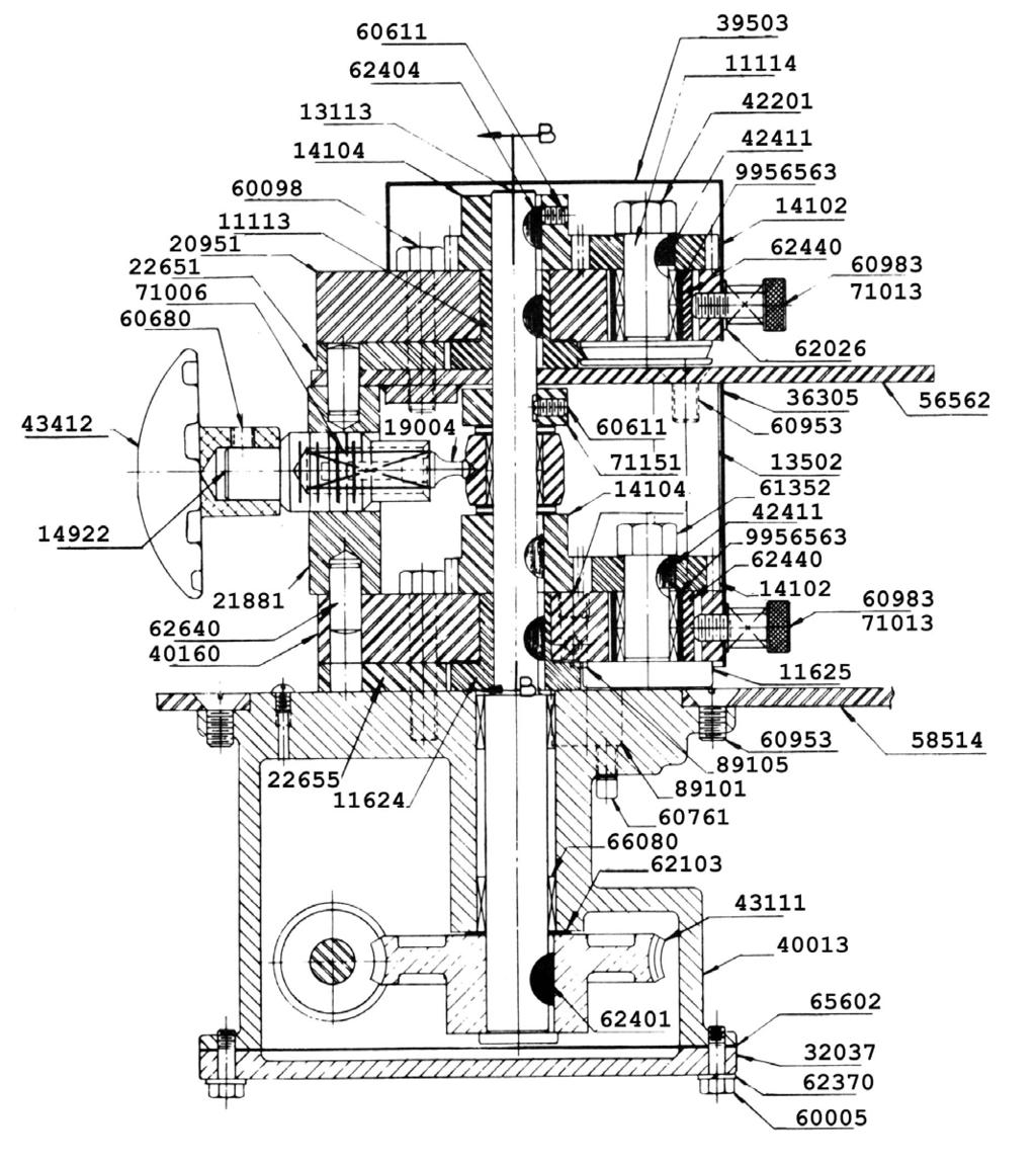
1 Capacity: 20 to 28 Gauge Galvanize Operating Instructions For Lockformer Button Punch Flanger To satisfactorily form the 90º button punch flange on light gauge materials, it was necessary to form the metal in two stages. Stage #1: To form the flange to the necessary height and Stage #2: To introduce the button punch to the flange. Operation Stage #1 (A) Adjust the Front Adjusting Screw ( on drawing ) to the gauge material to b flanged. Note: An Indicator punch mark is located on the end of the screw for reference. The reference mark will be on top when the adjusting screw is tight. To adjust tighten screw by hand. See Sketch A) Loosen screw required amount for the material being formed. *1/8 to 1/4 turn Gauge "B" *1/4 to 3/8 turn 24 Gauge C *3/8 to 1/2 turn 22/20 Gauge "D" *The above settings are approximate and will vary due to grades and type of galvanized sheets used. Practice and use will yield the exact setting for specific metals. Important: Do not set front adjusting screw too tight. It should be set just tight enough to draw the metal through the rolls. Too tight of a setting will stretch and wrinkle the material or stall the machine. (B) Adjust the Tension Screw (Hand Screw On Back Of Machine 14922). Tighten and loosen screw the required amount for material to be formed. 20 Gauge 1 Turn Loose 22 Gauge 1 Turn Loose 24 Gauge 11/4 to 2 Turns Loose 26 Gauge 3 Turns Loose 28 Gauge 31/4 Turns Loose (C) Turn Up A Starting Flange on the material before inserting it into the rolls. This is done by inserting the leading edge of the work to be flanged in the slot cut into the table and bending the piece away from the operator. It is most important to turn up a FULL 3/8 Flange at the beginning since this controls the height and also since button will not punch if flange is not at proper height. Start the material into the rolls on the lower stage of the machine. As the material passes through the rolls, the compensator arm will make contact with the material and guide it through the rolls. If the material pulls out of the rolls it is an indication that either front adjusting screw is too loose or the back tension screw is not tight enough. Important: Rated capacity of this machine is 20 to 28 Gauge galvanize. In running the lighter range of materials (26 to 28 gauge) it is most important that the back adjusting dial and front screw be at the proper settings. A wavy flange and an
2 incorrect height will result if these instructions are not carefully followed. To adjust tool for 28 gauge screw front adjusting screw (thumb screw in lower unit ) tight and loosen 1/8 turn. Adjust the tension screw (hand screw on back of machine ) tight and loosen 31/4 turns. Proper adjustments will result with a smooth regular flange. Too much pressure will create a buckled flange showing a heavy knurl marking on the flanged edge of the material. Insufficient pressure will cause the material to slip in the rolls and not be powered through the machine. The buckled flange can also be caused by too much pressure being exerted by the pressure arm ( ). Consult settings on screws and adjust accordingly. A slight variance of the indicated readings may be required for various materials. A buckled flange can be corrected by moving the compensator arm back to its lock out position. Then run flange through the rolls only. Do not apply any pressure to the material but only support the piece as it goes through the machine. If the buckle is minor Stage Number 2 will remove it. Operation Stage #2 Adjust the front adjusting screw (60983) on the upper stage same as for the lower stage. 1/8 to 1/4 turn from tight "B" Gauge 1/4 to 3/8 turn from tight "C" 24 Gauge 3/8 to 1/2 turn from tight "D" 22/20 Gauge Run material through the upper section for punching operation. To eliminate galvanize accumulation on knurled forming roll, it may be necessary from time to time to apply either kerosene or a light machine oil to the knurled roll. This will aid in keeping the roll from an over-deposit galvanized material. If galvanized material packs into knurl recesses, it is desirable to clean this part with a scraping tool or wire brush and then oil. When running materials, other than cold roll steel or galvanized, e.g. aluminum stainless or copper, a slight modification of the standard settings may be required to operate properly. For Running: Aluminum, Copper (soft) Materials: The above materials will require a looser setting on both the front gauge (thickness ) setting and pressure setting (spring pressure). Experience or test settings will be required. Should material shear at the corner, the damage could be caused by excessive pressure or metal pick-up and "galling" on the lifter button. Where "galling" or metal pick-up is evident. the material will require lubrication to the part of the material being formed. Lubricants such as kerosene or a light machine oil should prove adequate. For Running: Stainless Steel or Hard Brass Materials: Increased spring pressure may be required for running certain types of stainless. A standard thickness setting is adequate. A drawing compound may be necessary to eliminate pick-up. A special aluminum bronze lifter button may be necessary for prolonged use of stainless materials. (A special quotation would be required for this button.) It is very important that the body parts top and bottom be made to conform to the cheeks. The radius of the body may be over formed slightly to allow easier insertion of the cheek section. Note: If cheeks are continuous arcs, very little difficulty should be experienced. However, straight to curve (inside or outside) to straight will require care when forming the
3 body so that the arc will be formed to the tangent of the radius. A plus or minus factor will cause difficulty in the final closing of the final elbow. Do not crush snap lock with pinch rolls when forming arcs. Allow adequate clearance between front rolls to pass lock through. There will be a certain amount of closing when forming by back (3rd) roll but not enough to affect snap. On small radius curves it is better to control formed curve by running larger diameter and then with hand pressure diminish radius with several passes through slip rolls. Parts List and Description Part Description Pieces No. Per Unit Assembly Dwg Gear Housing Gear Housing Cover Gear Housing Gasket 1 Hor. Drive Shaft Worm Gear 1 Taper Pin Thrust Bearing Bronze Bushing Freeze Plug Oil Seal Vertical Drive Shaft Worm Wheel Washer Drive Gear Woodruff Key # Housing Pin Vertical Drive Shaft Collar Lower Space Plate Upper Space Plate Lifter Button Plain Forming Roll Knurled Forming Roll Woodruff Key # Thrust Race Thrust Bearing Compensator Arm Gear Flange Plate Weldment Vertical Spacer Inner Race Assembly Tension Screw Support Pivot Dowel Top Flanger Block Bottom Flanger Block Spring Tension Spring Push Rod Race Support Key Adjusting Handle Button Punch-Male Roll 1 Part Description Pieces No. Per Unit Button Punch-Female Roll Gear Adjusting Guide Roll Adjusting Guide Roll Shaft Sensory Head Screw Spring Modified Woodruff Key # Tension Screw Rd. Hd. Mach. Screw - # Hot. Pt. Hol. Set Screw - 1/ Hol. Pt. Hol. Set Screw - 5/ Hol. Pt. Sq. Hd. Set Screw - 5/ Hex Nut-Special - 1/ Hex Hd. Cap Screw Soc. Hd. Cap Screw Fl. Hd. Mach. Screw Hex Hd. Cap Screw Lock Washer - 1/ Cover Side Cover Stand Motor Motor Sheave Machine Pulley V Belt BX Connectors BX Cable Carriage Bolt - 3/ Hex Nut - 3/ Washer - 3/ Switch 1 M50 Handy Box Handy Box Cover Extension Cord x I-lY4 H. H. Cap Screw /16-18 HN. HVY. SF Washer 5/ Hex Hd. Cap Screw - 1/ Hex Jam Nut - 1/ Cup Pi. Hol. Set Screw - 7/ Washer - 3/ Hex Nut Special 1
4
5
6
7
8
TO OPERATE AUTO-GUIDE POWER. 24 Gauge Pittsburgh Operating Instructions FLANGING ATTACHMENT
 24 Gauge Pittsburgh Operating Instructions Holding the material against the angle gauge slide it into the forming head. Be sure that the material remains against the gauge until work is finished. Make
Operating Instructions
 Operating Instructions Holding the material against the angle gauge slide it into the forming head. Be sure that the material remains against the gauge until work is finished. NOTE: This machine will handle
24 GA. PITTS ROLLFORMER
 1 TIN KNOCKER 24 GA. PITTS ROLLFORMER INSTRUCTIONS & PARTS DIAGRAM Shown with Stand and Optional Flanging Attachment Rev. 092606 TAAG MACHINERY CO. (Master Distributor) 1257-B Activity Dr. Vista, CA 92081
INSTRUCTION MANUAL AND PARTS LIST MODEL 14-10
 VERTICAL BAND SAWS INSTRUCTION MANUAL AND PARTS LIST MODEL 1-10 DAKE/PARMA WHEN ORDERING PARTS GIVE COMPLETE SERIAL NUMBER OF MACHINE GIVE PART NUMBER AND NAME GIVE AMOUNT REQUIRED Unless the above data
Geology, Prospectors, Mining, Metallurgy, Assaying, Environmental, Geotechnical
 LEGEND INC. Geology, Prospectors, Mining, Metallurgy, Assaying, Environmental, Geotechnical 988 Packer Way Sparks, NV 89431 Tel: (786) 786-3003 Fax: (775) 786-3613 Email: info@lmine.com Web: www.lmine.com
Horizontal and Vertical. Metal Cutting Band Saw MODEL: BS-115
 Horizontal and Vertical Metal Cutting Band Saw MODEL: BS-5 SAFETY. Know your band saw. Read the operator s Manual carefully. Learn the operations, applications and limitation.. Use recommended accessories.
Astro-Physics Inc. 400QMD Lubrication/Maintenance Guide
 Astro-Physics Inc. 400QMD Lubrication/Maintenance Guide The following guidelines should be followed to lubricate the three main parts of the 400QMD mount. The QMD stands for Quartz Micro-Drive controller.
Lockformer / 16 Gauge Speednotch
 Lockformer / 16 Gauge Speednotch INSTALLATION PRELIMINARY: After uncrating, locate unit, with or without base skid, to area of operation. Unbind foot switch cord and cylinder hoses and remove gauge pin
OPERATION & MAINTENANCE MANUAL
 OPERATION & MAINTENANCE MANUAL AUTOMATIC PECAN CRACKER Food Processing Equipment and Machinery Specializing in the Pecan Industry Mailing: PO Box 817, Mansfield, Louisiana 71052 Located: 280 Independence
Number Wheeler P/N Description Set Rex P/N Notes Base 1 J Support, Right 1 J Support, Left 1 J Nut (M8)
") 1 603500 Base 1 J001 2 603501 Support, Right 1 J002 3 603502 Support, Left 1 J003 4 600328 Nut (M8) 4 5 600130 Spring Washer (8mm) 4 6 600344 Roll Pin (M6x30) 4 7 600129 Socket Hd Cap Screw (M8x25) 4 8
1 603500 Base 1 J001 2 603501 Support, Right 1 J002 3 603502 Support, Left 1 J003 4 600328 Nut (M8) 4 5 600130 Spring Washer (8mm) 4 6 600344 Roll Pin (M6x30) 4 7 600129 Socket Hd Cap Screw (M8x25) 4 8
ITEM NO. PART NO DESCRIPTION QTY.
 PUMP MAINTENANCE ITEM NO. PART NO DESCRIPTION QTY. 1 52002 Center Case 1 2 52052 Back End Plate 1 3 52051 Front End Plate 1 4 55090 Octagonal Nut 1 5 53001 Idler Gear 1 6 53002 Drive Gear 1 7 28062 Bushing
INSTRUCTIONS & PARTS LIST FOR HAND BRAKES
 INSTRUCTIONS & PARTS LIST FOR HAND BRAKES MODELS 144-22, 168-22, 192-22, 120-16, 120-14 When ordering repair parts, please refer to the item number, quantity, name of part, part number and serial number
RECOMMENDED SPARE PARTS FOR NORMAL ONE (1) YEAR OPERATION OF VD CRUSHER
 YEAR OPERATION OF VD CRUSHER") RECOMMENDED SPARE PARTS FOR NORMAL ONE (1) YEAR OPERATION OF VD CRUSHER 2 ea. VD-65 Toggle 2 ea. VD-70A Right Hand Bearing Split Bushing 2 ea. VD-70B Left Hand Bearing Split Bushing 2 ea. VD-82 Plate for
RECOMMENDED SPARE PARTS FOR NORMAL ONE (1) YEAR OPERATION OF VD CRUSHER 2 ea. VD-65 Toggle 2 ea. VD-70A Right Hand Bearing Split Bushing 2 ea. VD-70B Left Hand Bearing Split Bushing 2 ea. VD-82 Plate for
Parts Catalog. S-Series Slicer Manual Frozen Option S13. Model:
 , 07 995 ECN 08 Parts Catalog S S-Series Slicer Manual Frozen Option Model: S 05/0/07 Rev. G IMPORTANT! TO EXPEDITE SHIPMENT OF PARTS, ALWAYS SPECIFY MODEL, REV, PART NUMBER, AND SERIAL NUMBER OF UNIT.
SERVICE MANUAL AND PARTSLIST
 SERVICE MANUAL AND PARTSLIST Next 20 CONTENTS WHAT TO DO WHEN... 1~3 SERVICE ACCESS FACE COVER... 4 TOP COVER... 4 BASE COVER... 5 REAR COVER... 6 FRONT COVER... 7 MECHANICAL ADJUSTMENT NEEDLE THREAD TENSION...
Model No: TC10. Parts Information: Tyre Changer - Automatic
 Page 1 of 11 1 TC10.01 BODY 2 TC10.02 COLUMN 3 TC10.03 HORIZONTAL ARM ASS'Y 4 TC10.04 WASHER 5 TC10.05 RUBBER FOOT 6 TC10.06 COVER 7 TC10.07 SCREW M14x42 8 TC10.08 PRESS COVER 9 TC10.09 STOP-UP 10 TC10.10
MODEL 36 Di-Acro Hand Shear
 OPERATOR S MANUAL & INSTRUCTIONS MODEL 36 Di-Acro Hand Shear Di-Acro, Incorporated PO Box 9700 Canton, Ohio 44711 3713 Progress Street N.E. Canton, Ohio 44705 330-455-1942 330-455-0220 (fax) Revised 01/02
General Four-Way Operation, Maintenance & Service Manual
 General Four-Way Operation, Maintenance & Service Manual SCOPE Included in the following pages you will find assembly drawings, exploded views, parts lists, assembly tips, operational descriptions and
HANDWHEEL ASSEMBLY UPGRADE
 HANDWHEEL ASSEMBLY UPGRADE PURPOSE The purpose of the notice is to document the procedures involved in removing old handwheel assembly parts and replacing them with new parts. The new parts allow the handwheel
Model: 3-IN-1/1067x1.5 Model: 3-IN-1/1320x1.5
 SHEARER/PRESS BRAKE/ SLIP ROLL Model: 3-IN-1/1067x1.5 Model: 3-IN-1/1320x1.5 OPERATION MANUAL 1. USES This machine is used for shearing and bending low carbon plate (mild steel) or the other metal materials
SERVICE PARTS LIST PAGE 1 OF 6 BASE ASSEMBLY SPECIFY CATALOG NO. AND SERIAL NO. WHEN ORDERING PARTS 12" SLIDING COMPOUND MITER SAW
 PAGE 1 OF 6 BASE ASSEMBLY 00 0 CATALOG NO. EXAMPLE: SPECIFY CATALOG NO. AND NO. WHEN ORDERING PARTS 6955-20 1 02-80-0050 Thrust Bearing (1) 2 05-80-0510 M5 x 12mm Flat Head T-20 Screw (5) 3 05-81-0135
HYDRAULIC CONTROL DETAILS PARTS LIST
 Always give model number, serial number and part number when ordering repair parts. HYDRAULIC CONTROL DETAILS PARTS LIST REF NO. PART NUMBER DESCRIPTION 1 101939 Hydraulic Tank 2 101940 Hydraulic Tank
Lumber Smith. Assembly Manual. If you are having problems assembling the saw and need assistance, please contact us at:
 Lumber Smith Assembly Manual If you are having problems assembling the saw and need assistance, please contact us at: 804-577-7398 info@lumbersmith.com 1 Step 1 Safety Carefully read the Owners Manual.
Parts Catalog. S-Series Slicer Smart Manual SG13. Model:
 , 07 99507 ECN 065 Parts Catalog S-Series Slicer Smart Manual Model: SG SG 0/0/07 Rev. G IMPORTANT! TO EXPEDITE SHIPMENT OF PARTS, ALWAYS SPECIFY MODEL, REV, PART NUMBER, AND SERIAL NUMBER OF UNIT. GLOBE
CONCRETE SAW PARTS LIST
 CONCRETE SAW PARTS LIST MODEL CCXL-EE December 01 Part # 1 Intentionally Blank Table of Contents Description Page No. Frame Assembly... Carriage Assembly Motor Assembly.... Blade Shaft Assembly... Spring
PARTS LIST COMMANDER 20 VAC-TRAC COMMANDER 27 VAC-TRAC FH 541V
 PARTS LIST COMMANDER 20 VAC-TRAC COMMANDER 27 VAC-TRAC FH 541V UPPER ASSEMBLY 101 6190481 THROTTLE CABLE FOR MODELS WITH ADDITIONAL CHOKE CABLE 1 101 6190751 THROTTLE CABLE FOR MODELS WITH OUT ADDITIONAL
No. 412, 414, 416 Operations Manual
 No. 412, 414, 416 Operations Manual CARE: Occasional oiling of moving parts with machine oil will ease operation and extend the life of the brake. Occasionally check and tighten the lower beam bracket
PARTS G9729 Lathe Bed
 PARTS G9729 Lathe Bed 114 132 126 125 131 133 129 128 130 127 139 124 10 124 123 122 135 137 147 144 121 148 146 149 136 138 140 150 152 142 143 141 151 153 21 168 20 19 18 17 162 22 147 13315 14 13131
3850, Drum & Disc Brake Lathes. Parts Identification
 3850, 3860 Drum & Disc Brake Lathes Parts Identification READ these instructions before placing unit in service. KEEP these and other materials delivered with the unit in a binder near the machine for
Motorized M3 AX7200 Rotary-Style Gasket Cutter Operating Instructions
 Motorized M3 AX7200 Rotary-Style Gasket Cutter Operating Instructions INTRODUCTION Congratulations! You are the owner of the finest rotary-style gasket cutter in the world. Originally developed and patented
SERVICE PARTS LIST PAGE 1 OF 6 BASE ASSEMBLY SPECIFY CATALOG NO. AND SERIAL NO. WHEN ORDERING PARTS 12" DUAL BEVEL COMPOUND MITER SAW B27B
 PAGE 1 OF 6 BASE ASSEMBLY 00 0 EXAMPLE: Component Parts (Small #) Are Included When Ordering The Assembly (Large #). SPECIFY CATALOG NO. AND NO. WHEN ORDERING PARTS = Part number change from previous service
STARTING SERIAL NUMBER PARTS LIST FOR. Wellsaw MODEL 600 METAL CUTTING BAND SAW
 STARTING SERIAL NUMBER 11075 PARTS LIST FOR Wellsaw MODEL 600 METAL CUTTING BAND SAW Wellsaw 2829 N. Burdick, Kalamazoo, MI 49004 Phone: 269-345-1132 Fax: 269-345-0095 Rev 171005 INSTALLATION, OPERATION
c. Pins, bolts, and retaining rings b. Washers, locking nuts, and rivets
 62 20 HW 8: Fasteners / Force, Pressure, Density Mechanical Systems DUE Mon, 11/21/16 Start of class Check link on website for helpful fastener information Please use a scantron. Material is based primarily
CATALOG OF REPLACEMENT PARTS
 The Choice of Experience CATALOG OF REPLACEMENT PARTS MODELS 909A 919A 909E 919E 909M 919M SLICERS EFFECTIVE MARCH 2009 - 2 - Table of Contents 5 ELECTRICAL COMPONENTS (909A & 919A) 7 ELECTRICAL COMPONENTS
DRIVE COMPONENTS REMOVAL. 9. FXCW/C: see Figure Remove bolt (9), sprocket retainer (8), and thrust washer (7). NOTE PRIMARY DRIVE LOCKING TOOL
, sprocket retainer (8), and thrust washer (7). NOTE PRIMARY DRIVE LOCKING TOOL") DRIVE COMPONENTS REMOVAL PART NUMBER HD-7977 TOOL NAME PRIMARY DRIVE LOCKING TOOL S To remove the primary chain, remove compensating sprocket, clutch assembly and primary chain as an assembly:. Remove
DRIVE COMPONENTS REMOVAL PART NUMBER HD-7977 TOOL NAME PRIMARY DRIVE LOCKING TOOL S To remove the primary chain, remove compensating sprocket, clutch assembly and primary chain as an assembly:. Remove
DIAMOND MODEL CC1900 EARLY ENTRY CONCRETE SAW PARTS LIST P R O D U C T S. (March 2012) Part #
 Part #") DIAMOND P R O D U C T S EARLY ENTRY CONCRETE SAW PARTS LIST MODEL CC1900 (March 2012) Part #1801617 (Intentionally Blank) TABLE OF CONTENTS Description Page No. Frame Assembly....4-5 Engine Assembly......6
DIAMOND P R O D U C T S EARLY ENTRY CONCRETE SAW PARTS LIST MODEL CC1900 (March 2012) Part #1801617 (Intentionally Blank) TABLE OF CONTENTS Description Page No. Frame Assembly....4-5 Engine Assembly......6
How to program the digital speed display (This is factory set and will only need to be programmed if the unit is replaced)
") How to program the digital speed display (This is factory set and will only need to be programmed if the unit is replaced) 1. Press and hold the set button (top left corner) until the display shows Fun
How to program the digital speed display (This is factory set and will only need to be programmed if the unit is replaced) 1. Press and hold the set button (top left corner) until the display shows Fun
BABY WOLF LOOM. Assembly Instructions for Knocked-Down Looms
 BABY WOLF LOOM Assembly Instructions for Knocked-Down Looms BEFORE YOU BEGIN Please read through the directions before beginning to assemble your loom. Unpack the loom parts carefully. Do not throw away
RP-VE416FS/FSD VE416FS and VE416FSD Roll Grooving Tools
 PARTS ORDERING INFORMATION When ordering parts, the following information is necessary for Victaulic to process the order promptly: 1. Tool Model Number VE416FS or VE416FSD 2. Tool Serial Number The Serial
HOME WORKSHOP HANDBOOK Rugged BENCH GRINDER. By JOEL B. LONG
 6 HOME WORKSHOP HANDBOOK Rugged BENCH GRINDER W By JOEL B. LONG ITH this bench grinder you can keep your cutting tools sharp and do general offhand grinding, and can, with the aid of various attachments,
FOR YOUR SAFETY: READ ALL INSTRUCTIONS CAREFULLY
 MODEL 2020F FOR YOUR SAFETY: READ ALL INSTRUCTIONS CAREFULLY Table of Contents General safety instructions for Power Tools 1 Main specification 2 Unpacking and checking contents 2 List of loose parts in
Main Drive Components
 Pipe and Bolt Threading Machine Main Drive Components 0 0 Rear Centering Head Centering Jaw Set Spiral Pins () 00 Centering Scroll Retaining Ring 0 Rear Bearing 0 Oil Ball Valve () # - x / Screw Motor
DIAMOND CONCRETE SAW PARTS LIST MODEL CC1113-XL P R O D U C T S. June Part #
 DIAMOND P R O D U C T S CONCRETE SAW PARTS LIST MODEL CC1113-XL June 013 Part #10 TABLE OF CONTENTS Description Page No. Saw Assembly (Normal Cut).... - Saw Assembly (Up-Cut)...... - Gas Engine Assembly......
M2 Assembly. M2 Sub-Assemblies mm Belt Sub-Assembly mm Belt Sub-Assembly Spider Sub-Assembly... 4
 M2 Assembly Table of Contents M2 Sub-Assemblies... 3 630mm Belt Sub-Assembly... 3 702mm Belt Sub-Assembly... 3 Spider Sub-Assembly... 4 Idler Bolt Sub-Assembly... 8 Y Motor Sub-Assembly... 9 X Motor Sub-Assembly...
OPERATIONS MANUAL. Port-O-Slitter
 Tapco Products Company The World Leader in Specialty Tools for the Professional Port-O-Slitter OPERATIONS MANUAL General instructions, set up, accessories and guide to using your portable precision slitting,
RTI TECHNOLOGIES, INC.
 RTI TECHNOLOGIES, INC. BRC500 & BRC550 Arbor/Spindle Mechanism Adjustment & Service Technical Instructions The arbor/spindle mechanism of the BRC500/550 is designed to be robust for long life. Occasionally
Operating Instructions and Parts Manual 5-ft. Radial Arm Drill Press Models J-1600R, J-1600R-4
 Operating Instructions and Parts Manual 5-ft. Radial Arm Drill Press Models J-1600R, J-1600R-4 JET 427 New Sanford Road LaVergne, Tennessee 37086 Part No. M-320038 Ph.: 800-274-6848 Revision H 01/2016
32 FRONT DECK ASSEMBLY
 3 6 K 2 0 PARTS MANUAL 32 FRONT DECK ASSEMBLY 3 1 2 Belt Shield Prior to SN 33333 4 6 21 22 7 24 2 26 14 8 13 12 9 10 11 27 2 28 1 16 2 19 17 30 36 39 39 37 29 60 62 61 3 9 49 41 40 28 48 42 13 43 44 47
535A. Main Components. Pipe and Bolt Threading Machine. Printed in U.S.A. Ridge Tool Company/Elyria, Ohio, U.S.A.
 Pipe and Bolt Threading Machine A Main Components 0 Screw, Button Head /" - 0 x /" () Washer, Flat /" ()" Top Cover 0 Base Bottom Cover Screw, Pan Head # - x " () Carriage Assembly 0 Front Support Bar
535-Manual. Main Components. Pipe and Bolt Threading Machine. Printed in U.S.A. Ridge Tool Company/Elyria, Ohio, U.S.A.
 Pipe and Bolt Threading Machine -Manual Main Components 0 Screw, Button Head /" - 0 x /" () Washer, Flat /" ()" Top Cover 0 0 Cutter Assembly Stop Pin 0 Pin Reamer Assembly Carriage Assembly 0 Stop Screw
PET*STAR 4 OPERATOR MANUAL
 Operator Manual 17315060 Rev. 0 (PS - 4) PET*STAR 4 OPERATOR MANUAL Paragraph Page 1.0 INTRODUCTION... 2 2.0 INSTALLATION... 2 3.0 ALIGNMENT... 2 4.0 SPHERICAL ROLLER BEARING & PILLOW BLOCK... 5 5.0 OUTBOARD
400A 40113V, 401A 40120V, & 401AL 40120VL ALUMINUM VERTICAL 4000 LB LIFT INCLUDES SCREW LEG ASSEMBLY INSTRUCTIONS
 12/11/07 PAGE 1 OF 12 400A 40113V, 401A 40120V, & 401AL 40120VL ALUMINUM VERTICAL 4000 LB LIFT INCLUDES SCREW LEG ASSEMBLY INSTRUCTIONS Thank you for purchasing our product! *Please read these instructions
Tire Chain Kit. Replacing Shear Pins. Weight Kits. Drift Cutter
 Replacing Shear Pins The augers are secured to the spiral shaft with two shear pins and cotter pins. If the auger should strike a foreign object or ice jam, the snow thrower is designed so that the pins
ORTOP Modular Robot v3.0 Arm Assembly
 Base Plate Assembly Parts Needed: Arm Assembly BAG 1 2 Socket Head Cap Screw, 1-1/4" 2 Socket Head Cap Screw, 1/2" 2 Button Head Cap Screw, 3/8" 6 Nuts 1 Gear Hub Spacer 1 Flat Building Plate 1 Single
Inventory (Figure 2)
") MODEL T10127 12" SPIRAL CUTTERHEAD INSTRUCTIONS The Model T10127 indexable insert spiral cutterhead is designed to replace the straightknife cutterhead from the Grizzly jointer Model G0609. The total procedure
MODEL T10127 12" SPIRAL CUTTERHEAD INSTRUCTIONS The Model T10127 indexable insert spiral cutterhead is designed to replace the straightknife cutterhead from the Grizzly jointer Model G0609. The total procedure
PARTS LIST. Clarke CL500M 6 spd. Metal Lathe Part Number: HT HT HT
 PARTS LIST Clarke CL500M 6 spd. Metal Lathe Part Number: - 7610300 Quantity Description Part Number 1 Countersunk Hd, screw m5x14 HT3000101 1 Retaining Ring, 28 HT3000102 1 Bevel Gear HT3000103 1 Washer
OPERATION, PARTS & MAINTENANCE MANUAL MODELS HB73-16 HB97-18 HB97-16 HB97-12 HB HB HB HB145-18
 OPERATION, PARTS & MAINTENANCE MANUAL MODELS HB73-16 HB97-18 HB97-16 HB97-12 HB121-18 HB121-16 HB121-14 HB145-18 Proudly Made in the USA 2 3 4 FOREWORD This manual has been prepared for the owner and operators
Form No Assembly & Operating Instructions for: SAFETY PRECAUTIONS
 Form No. 0230 Assembly & Operating Instructions for: 833 20300 83 2220 837 0-0008 078 SHOP PRESS Max. Capacity: 2 Ton These instructions are intended for various shop presses. Some models are shipped assembled
400 SERIES GRINDER PUMPS 41502, 42202,43302, AND MODELS
 Section: MOYNO 500 PUMPS Page: 1 of 6 Date: March 1, 1998 SERVICE MANUAL MOYNO 500 PUMPS 400 SERIES GRINDER PUMPS 41502, 42202,43302, AND 44402 MODELS DESIGN FEATURES Housing: Cast iron Pump Rotor: Chrome
M-5 PRO CORE BORE PARTS LIST DRILLING MACHINE. (March 2017) Part #
 Part #") M- PRO CORE BORE DRILLING MACHINE PARTS LIST (March 07) Part #809 Table of Contents Description Page No. Carriage Assembly....... - Combo Base Assembly....... - 7 Anchor Base Assembly........8 Anchor
M- PRO CORE BORE DRILLING MACHINE PARTS LIST (March 07) Part #809 Table of Contents Description Page No. Carriage Assembly....... - Combo Base Assembly....... - 7 Anchor Base Assembly........8 Anchor
SECTION 9: PARTS. Table Breakdown REF PART # DESCRIPTION REF PART # DESCRIPTION
 SECTION 9: PARTS Table Breakdown 1 2 3 4 5 6 7 8 9 10 11 12 13 14 15 16 17 18 19 20 21 22 23 24 23 25 17 26 27 8 1 P0675001 CAP SCREW M8-1.25 X 30 15 P0675015 SUPPORT BLOCK 2 P0675002 TABLE SUPPORT BLOCK
MODEL H-9 HEAVY DUTY BENCH-TYPE UNDERCUTTER INSTRUCTIONS
 MODEL H-9 HEAVY DUTY BENCH-TYPE UNDERCUTTER INSTRUCTIONS CAPACITY: Between centers - 32" long x 12" diameter. Between roller V- supports - 35" long x 17" diameter. Maximum armature weight - 200 lbs. SAW
CATALOG OF REPLACEMENT PARTS
 CATALOG OF REPLACEMENT PARTS MODEL 6115 POTATO PEELER ML-137600 ML-137601 PRIOR MLS COVERED IN THIS CATALOG ML-19869 ML-19683 A product of HOBART 701 S. RIDGE AVENUE TROY, OHIO 45374-0001 FORM 43064 Rev.
Parts Catalog. S-Series Slicer Smart Manual SG13. Model:
 , 08 99507 ECN 065 Parts Catalog S-Series Slicer Smart Manual Model: SG SG /6/08 Rev. R IMPORTANT! TO EXPEDITE SHIPMENT OF PARTS, ALWAYS SPECIFY MODEL, REV, PART NUMBER, AND SERIAL NUMBER OF UNIT. GLOBE
BICO BADGER 5" X 7" JAW CRUSHER OPERATING INSTRUCTIONS
 BICO BADGER 5" X 7" JAW CRUSHER OPERATING INSTRUCTIONS The Bico Badger Jaw Crusher is designed to give long and efficient service. In order to secure the long life and excellent performance, which your
MODEL T " HELICAL CUTTERHEAD INSTALLATION INSTRUCTIONS
 MODEL T27696 12" HELICAL CUTTERHEAD INSTALLATION INSTRUCTIONS For questions or help with this product contact Tech Support at (570) 546-9663 or techsupport@grizzly.com Introduction The Model T27696 indexable
Inventory MODEL T10096 TAPER ATTACHMENT FOR G0509 & G0509G LATHE INSTRUCTIONS. Inventory (Figure 1) Needed Items
 Needed Items") MODEL T10096 TAPER ATTACHMENT FOR G0509 & G0509G LATHE INSTRUCTIONS Inventory The Model T10096 taper attachment was carefully packed when it left our warehouse. If you discover it is damaged after you
MODEL T10096 TAPER ATTACHMENT FOR G0509 & G0509G LATHE INSTRUCTIONS Inventory The Model T10096 taper attachment was carefully packed when it left our warehouse. If you discover it is damaged after you
Page 1. SureMotion Quick-Start Guide: LACPACC_QS 1st Edition - Revision A 03/15/16
 R K C T I Repair Kit Product Compatibility Repair Kit # Linear Actuator Assembly # LACPACC-002 LACPACC-003 LACP-16TxxLP5 (0.5-in lead screw pitch) LACP-16TxxL1 (1-in lead screw pitch) C P I R K 4 ea Flanged
SECTION 9: PARTS. Headstock A 126A 127A-1 REF PART # DESCRIPTION REF PART # DESCRIPTION
 SECTION 9: PARTS Headstock 120 121 113 115 112 111 110 109 108 105 106 107 135 101 119A 121 120 118 114 115 107 106 104 123 122 118 114 126A 105 126 103 102 126B 127A-1 131 127A 124 133 134 126C 129 130
30AUTO Speed Lathe Manual
 30AUTO Speed Lathe Manual Standard Features 3/4 HP Motor Air-Collet Closure 1800 RPM, Single Speed Electric Brake Cast Housing 5C Collets 3 Phase / 240 Volts DESCRIPTION: The Crozier Model 30AUTO Automotive
 Planer/Moulder Head USE helpers or power lifting equipment to lift this Planer/Moulder. Otherwise, serious personal injury may occur. To mount the Planer/Moulder head, do these steps: 1. Lay two 2x4 s
Maintenance & Parts list for:
 Maintenance & Parts list for: Industrial gun GB 2 Juni 2017 This Maintenance & Parts list for industrial gun is prepared by : Winchester Europe Service V. Parbst & Søn as a comprehensive maintenance guide
SECTION 9: PARTS. Electrical REF PART # DESCRIPTION REF PART # DESCRIPTION
 SECTION 9: PARTS Electrical 1 P4002001 START BUTTON 52 P4002052 CONTACTOR GSC1CJX4-D 110V 2 P4002002 INDICATOR LIGHT 53 P4002053 CONTACTOR JZC3-40D 110V 3 P4002003 JOG BUTTON 54 P4002054 FUSE HOLDER 4
REPAIR INSTRUCTIONS. Cat. No Cat. No MILWAUKEE ELECTRIC TOOL CORPORATION. SDS Max Demolition Hammer. SDS Max Rotary Hammer
 Cat. No. 9-0 SDS Max Demolition Hammer Cat. No. -0 SDS Max Rotary Hammer MILWAUKEE ELECTRIC TOOL CORPORATION W. LISBON ROAD BROOKFIELD, WISCONSIN 00-0 8-9-0 d 000 8-9-0 d Special Tools Require Forcing
Kossel Rev B Build Guide V1.0
 Kossel Rev B Build Guide V1.0 1 Table of Contents: Step 1: BASE ASSEMBLY Gathering parts: Building the Corners and Base: Step 2: UPPER ASSEMBLY Building Upper: Step 3: VERTICAL RAIL INSTALLATION Building
LU6X-130 Instructions and Parts List (including LU6X Basic) Operating Instructions
 Operating Instructions") LORTONE LU6X-130 Item # 061-092 LU6X Basic Item # 061-090 LU6X-130 Instructions and Parts List (including LU6X Basic) Operating Instructions Introduction The LU6X is one the most versatile pieces of equipment
LORTONE LU6X-130 Item # 061-092 LU6X Basic Item # 061-090 LU6X-130 Instructions and Parts List (including LU6X Basic) Operating Instructions Introduction The LU6X is one the most versatile pieces of equipment
G0513X2 Main -87- G0513 Series Bandsaws 82V V2 82-6V2 95A V2 82-5V2 82-1V2 82-4V V A
 G0513X2 Main 23 55 22 48 17 17-1 17-2 21 7 17-3 17-2 17-4 24 17-5 18-5 22 24 21 55A 50 8 9 49 11 12 13 14 15 47 16 10 46 45 3 44 43 39 38 37 39 40 32 33 36 42 34 35 2 25 28 18-4 18-2 18-3 31 30 29 18-1
TK 1014 A POWER SHEAR
 TIN KNOCKER TK 1014 A POWER SHEAR Parts Diagram & Operating Instructions TAAG INDUSTRIES CORP. 1550 SIMPSON WAY, ESCONDIDO, CA 92029 Tel: (800) 640-0746 Fax: (760) 727-9948 Website: www.tinknocker.com
FBX1104P FBX1104 FBX1106P FBX1106
 FBX1104P FBX1104 FBX1106P FBX1106 Second edition : September 2004 No. 040037 INTRODUCTION Thank you for your purchasing Kansai Special's FBX Series. Read and study this instruction manual carefully before
MM540 Installation Instructions IMPORTANT SAFETY INSTRUCTIONS - SAVE THESE INSTRUCTIONS
 MM50 Installation Instructions IMPORTANT SAFETY INSTRUCTIONS - SAVE THESE INSTRUCTIONS Please read this entire manual before you begin. Do not unpack any contents until you verify all requirements on PAGE.
INSTRUCTIONS AND PARTS LIST POWER HAMMER
 INSTRUCTIONS AND PARTS LIST POWER HAMMER DAKE (Division of JSJ) 724 Robbins Road Grand Haven, Michigan 49417 616.842.7110 Phone 800-937-3253 616.842.0859 Fax 800-846-3253 Web: www.dakecorp.com E-mail :
Di-Acro 18E Stylus Turret Punch Press
 OPERATOR S MANUAL & INSTRUCTIONS Di-Acro E Stylus Turret Punch Press Di-Acro, Incorporated PO Box 00 Canton, Ohio Progress Street N.E. Canton, Ohio 0 0-- 0--00 (fax) Revised 0/0 Sale or distribution of
SECTION 7. SAFETYING
 9/8/98 AC 43.13-1B SECTION 7. SAFETYING 7-122. GENERAL. The word safetying is a term universally used in the aircraft industry. Briefly, safetying is defined as: Securing by various means any nut, bolt,
MODEL NO.: MI PARTS BREAKDOWN
 MODEL NO.: MI-76350 PARTS BREAKDOWN MAGNUM DRILL PRESS ASSEMBLY INSTRUCTIONS MODEL MI-76350 Before you begin to assemble your drill press, review the parts breakdown and keep it ready for reference. Start
Inspection. Assembly Install the springs. 1. Discard the 0-rings. 2. Clean all parts in cleaning solvent.
 6010-34 Inspection 3. Install the springs. 1. Discard the 0-rings. 2. Clean all parts in cleaning solvent. 3. If spring test equipment is available, check the tension of each spring according to the specifications
The Phoenix. Professional Quilting Frame. Copyright January 1, 2016 Jim M. Bagley, GraceWood, Inc (Reproduction Prohibited) Version 2.
 Version 2.") The Phoenix Professional Quilting Frame Copyright January 1, 2016 Jim M. Bagley, GraceWood, Inc (Reproduction Prohibited) Version 2.1 1 The Phoenix Professional Quilting Frame Parts List Box 1...3 Box
The Phoenix Professional Quilting Frame Copyright January 1, 2016 Jim M. Bagley, GraceWood, Inc (Reproduction Prohibited) Version 2.1 1 The Phoenix Professional Quilting Frame Parts List Box 1...3 Box
Operation and Service Instructions With Replacement Parts List
 No. 700-F TUBE BENDER Operation and Service Instructions With Replacement Parts List Warning! Keep body parts away from pinch/bend areas while using. Ensure tubing is secure in tool before bending. Always
Main Breakdown. Model G0531B/G0566B V2 (G0531B) 80V2-2
 80V2-2") Main Breakdown 53 85-1 54 59 54 56 54 52 55 57 175 53 56 85 29 119-2 114 89 22 119-2 119 107 119-5 119-3 119-6 119-1 29 22 119-4 114 112 96 113 114 100 116 117 105 120 102 103 108 115 99 98 92 91 90 73
Main Breakdown 53 85-1 54 59 54 56 54 52 55 57 175 53 56 85 29 119-2 114 89 22 119-2 119 107 119-5 119-3 119-6 119-1 29 22 119-4 114 112 96 113 114 100 116 117 105 120 102 103 108 115 99 98 92 91 90 73
1822-I. Spindle Assembly. Pipe and Bolt Threading Machine. Ridge Tool Company/Elyria, Ohio, U.S.A. 2* 3 4 5* * *
 -I Pipe and Bolt Threading Machine Spindle Assembly * * * 0 * * * 0 * * 0* * * Rear Cover * Screw () * Washer () Top Cover w/clips (Includes,, ) * J Clip () Front Cover * Screw () Pivot Rod Support ()
CATALOG OF REPLACEMENT PARTS
 CATALOG OF REPLACEMENT PARTS 3000 SERIES AUTOMATIC SLICERS 3713 ML-136144 3713 (Canada) ML-136177 3713N ML-136181 3713N (Canada) ML-136184 3913 ML-136145 3913 (Canada) ML-136179 3913N ML-136183 3913N (Canada)
HD38, HD58, HD78 REV
 HD38, HD58, HD78 REV. 07.29.2014 COVER for HD38, HD58, HD78 5 P004868 1/4-20x3/4 Button Head Cap Screw Stainless Steel 2 6 P001450 Lockwasher - Internal Tooth.250 6 8 P005200 Wave Disc Washer 4 10 P004869
MM750 Installation Instructions
 MM750 Installation Instructions IMPORTANT SAFETY INSTRUCTIONS - SAVE THESE INSTRUCTIONS Please read this entire manual before you begin. Do not unpack any contents until you verify all requirements on
SUPER PRO GUN & SUPER PRO GUN II
 MAGNUM VENUS PRODUCTS Maintenance & Repair Manual Part No. M6707-1-1 Revision 04.14.01 Maintenance & Repair Corporate HQ & Mfg. Phone: (727) 573-2955 Fax: (727) 571-3636 Email: info@magind.com Web: www.magind.com
RYOBI 10 IN (254 MM) TABLE SAW MODEL NO. BT REPAIR SHEET
 TABLE SAW MODEL NO. BT REPAIR SHEET") RYOBI 0 IN (2 MM) TABLE SAW MODEL NO. BT00- REPAIR SHEET 2 RYOBI 0 in. (2 mm) TABLE SAW - MODEL NO. BT00- FOR MITER TABLE ASSEMBLY, REFER TO FIGURE B FOR BLADE GUARD ASSEMBLY, REFER TO FIGURE E FOR RIP
RYOBI 0 IN (2 MM) TABLE SAW MODEL NO. BT00- REPAIR SHEET 2 RYOBI 0 in. (2 mm) TABLE SAW - MODEL NO. BT00- FOR MITER TABLE ASSEMBLY, REFER TO FIGURE B FOR BLADE GUARD ASSEMBLY, REFER TO FIGURE E FOR RIP
CATALOG OF REPLACEMENT PARTS
 CATALOG OF REPLACEMENT PARTS HS4N SLICER ML-136338 HS4N A product of HOBART 701 S. RIDGE AVENUE TROY, OHIO 45374-0001 FORM 43311 (August 2015) F-43311 (August 2015) - 2 - HOBART 2015 Table of Contents
MODEL H " BYRD SHELIX CUTTERHEAD INSTRUCTIONS
 MODEL H9291 12" BYRD SHELIX CUTTERHEAD INSTRUCTIONS The Model H9291 12" Byrd Shelix cutterhead is designed to replace the straight-knife cutterhead on the Grizzly jointer Model G0609. The total procedure
MM340 Installation Instructions IMPORTANT SAFETY INSTRUCTIONS - SAVE THESE INSTRUCTIONS
 MM30 Installation Instructions IMPORTANT SAFETY INSTRUCTIONS - SAVE THESE INSTRUCTIONS Please read this entire manual before you begin. Do not unpack any contents until you verify all requirements on PAGE.
ABM International, Inc.
 ABM International, Inc. Lightning Stitch required 1 1.0: Parts List head and motor assembly (Qty. 1) Reel stand (Qty. 1) Needle bar frame clamp (Qty. 1) Motor drive (Qty. 1) 2 Cable harness with bracket
767, 777, DC-10, L-1011, MD-11 Tow Bar Equipment Manual
 514 MECKLEM LANE, ELLWOOD CITY, PENNSYLVANIA 16117 www.hallindustries.com E-mail: service@hallindustries.com 767, 777, DC-10, L-1011, MD-11 Tow Bar Equipment Manual Use This Manual for 1. Operating Procedures
Due to possible damage in shipping, the vertical stop assembly has been removed from this machine.
 Due to possible damage in shipping, the vertical stop assembly has been removed from this machine. To assemble, insert the threaded rod through the shroud opening in the top of the machine. Start the four