CNC Router Parts PRO Machine Kit Cable Track Installation Instructions
|
|
|
- Caroline Garrett
- 6 years ago
- Views:
Transcription


1 1

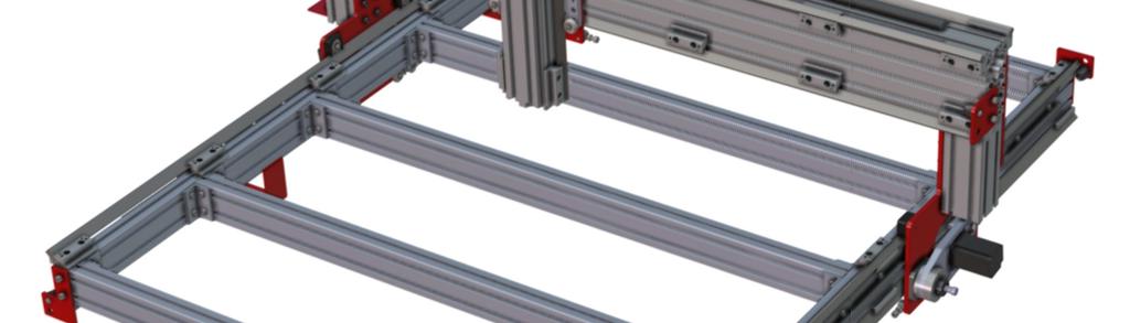
2 1 X CABLE TRACK TRAYS & BRACKETS The cable track on the side of the system is supported by a metal tray (or multiple trays for longer systems such as a PRO4896). These trays hang from brackets on the side of the machine. The cable track will attach to these trays and to a custom bracket on the gantry risers. Details on the installation of these trays and brackets are provided in the following steps. 2

3 1.1 INSERT T-NUTS INTO EXTRUSION First, install the roll-in t-nuts in the underside of the side rail extrusion. The Cable Tray Brackets will bolt into these t-nuts. Use the actual cable trays as a guide for where these will need to go. Install the brackets such that they support the trays close to the ends of the trays. Precise positioning of the trays is not important. Install the t-nuts such that you can avoid V-Con clamps and leg connections to your machine frame. 3

4 1.2 SLIDE BRACKET UNDER RAIL Slide the Cable Tray Brackets under the steel V-Con rail and position them so the holes align with the t-nuts you just installed. 4

5 1.3 LOOSELY FASTEN BRACKET TO EXTRUSION Loosely tighten the screws into the brackets. You will need to shift the brackets a little to get them to align with fastener holes in the Cable Trays, so don t overtighten at this point. 5

6 1.4 REPEAT STEPS 2 & 3 FOR REMAINING BRACKETS Repeat the installation for all of the Cable Tray Brackets in your kit. 6

7 1.5 SET CABLE TRAY ON SUPPORT BRACKETS Set the Cable Trays on the brackets you just installed. 7

8 1.6 FASTEN TRAY TO SUPPORT BRACKETS Slide the Cable Tray Brackets so the slots in the side of the bracket align with the side mounting holes in the Cable Trays. If you have a 4x8 or larger machine, install the Cable Trays such that they butt against each other. 8

9 1.7 TIGHTEN BRACKET FASTENERS Tighten the bolts to fasten the Cable Tray Brackets in position. 9

10 1.8 ATTACH RISER SUPPORT BRACKET TO EXTRUSION The next step is to attach the PRO Riser Cable Track Bracket. Fasten this to the gantry riser using the provided t-nuts and screws. If you installed the Cable Tray Bracket on the other side of your machine from this diagram, you can flip the PRO Riser Cable Track Bracket over. The bracket does not require precise positioning up and down, and can be adjusted later by sliding it in the t-slots of the gantry riser extrusion. 10

11 2 Y CABLE TRACK TRAY The gantry cable track rides in a tray that installs directly to the gantry. The following steps detail the installation of this tray. 11

12 2.1 INSERT T-NUTS INTO EXTRUSION First, install roll in t-nuts in the bottom t-slot on the back side of the gantry. 12

13 2.2 ALIGN T-NUTS WITH CABLE TRAY Shift the t-nuts with a screwdriver until they align with the mounting holes on the Cable Tray. 13

14 2.3 FASTEN CABLE TRAY TO EXTRUSION Fasten the Cable Tray to the gantry using the provided screws. 14
15 3 Z CABLE TRACK BRACKET The final bracket that needs to be installed is the Z-Axis Cable Track Support. This installation of this bracket depends on the type of motor being used on your Z axis. Instructions for systems with both NEMA 23 and NEMA 34 motors follow. 15

16 3.1 NEMA 23 MOTORS For NEMA 23 motors, use the provided 16mm screws to fasten through the bracket up into the mounting holes on the z axis motor plate. 16
17 3.2 NEMA 34 MOTORS For NEMA 34 motors, replace two of the M6 motor mounting screws with the longer 30mm M6 screws provided in the cable track kit. Slide the bracket over these screws and fasten in place with hex nuts. 17

18 4 CABLE TRACK Now that the brackets and trays are all installed, the cable track can be fastened to the machine. 18

19 4.1 OPENING CABLE TRACK Before installing the cable track, it can be helpful to open up the covers on it. This makes it easier to place cables into the track. The covers can be opened while the track is in the tray, but access is easier beforehand. 19

20 4.2 ATTACH X TRACK TO CABLE TRAY The cable track on the side of the machine should be fastened to the trays using the provided M6 hardware. The exact position in the tray is not critical. The front edge of the cable track should be roughly one third of the way back from the front of the machine. 20

21 4.3 ATTACH X TRACK TO RISER SUPPORT Once the cable track is attached to the tray, it should be router underneath the rack and pinion drive and attached to the PRO Riser Cable Track Bracket you installed in step

22 4.4 ATTACH Y TRACK TO CABLE TRAY The next step is to attach the gantry cable track. Like the previous connections, this is accomplished with the provided M6 socket heads, washers, and hex nuts. The end of the track should be positioned roughly one third of the way in from the right side of the gantry. 22

23 4.5 ATTACH Y TRACK TO GANTRY CARRIAGE The other end of the gantry cable track is attached simply with an M8 socket head screw, which fastens through the hole in the cable track and into the back gantry support. 23

24 4.6 ATTACH Z TRACK TO GANTRY CARRIAGE Attach the Z axis cable track to the back gantry support bracket with the supplied M6 screws. 24

25 4.7 ATTACH Z TRACK TO SUPPORT BRACKET Attach the other side of the z cable track to the Z Axis Cable Track support bracket with the supplied M6 screws. You should now be able to finish routing your cables through the system. 25
CRP700 Benchtop Basic CNC Machine Assembly Instructions. Updated 10/24/2014 SHEET 1 of 24
 CRP700 Benchtop Basic CNC Machine Assembly Instructions Updated 0//0 SHEET of NOTE: This piece of extrusion is mounted wide side up Quick Tip: Lay extrusion on table as shown for easy assembly BASE ASSEMBLY:.
CRP700 Benchtop Basic CNC Machine Assembly Instructions. Updated 9/11/2014 SHEET 1 of 25
 CRP700 Benchtop Basic CNC Machine Assembly Instructions Updated 9//0 SHEET of NOTE: This piece of extrusion is mounted wide side up Quick Tip: Lay extrusion on table as shown for easy assembly BASE ASSEMBLY:.
PRS X-Axis E-Chain Installation For Tools with a 12 Z-Axis
 888-680-4466 ShopBotTools.com PRS X-Axis E-Chain Installation For Tools with a 12 Z-Axis This kit is compatible with PRS Shopbots that have an X-axis cutting area of 96 to 144. It is not immediately compatible
PRS X-Axis Energy Chain (E-chain) Installation
 Installation") Page 1 PRS X-Axis Energy Chain (E-chain) Installation ShopBot Tools, Inc. 3333-B Industrial Drive, Durham NC 27704 ShopBotTools.com Technical Support support@shopbottools.com 1-888-680-4466 Page 2 Table
Page 1 PRS X-Axis Energy Chain (E-chain) Installation ShopBot Tools, Inc. 3333-B Industrial Drive, Durham NC 27704 ShopBotTools.com Technical Support support@shopbottools.com 1-888-680-4466 Page 2 Table
This manual will aid in the assembly of the FireBall V90 and FireBall X90. The assembly of both machines will be identical, unless specified.
 This manual will aid in the assembly of the FireBall V90 and FireBall X90. The assembly of both machines will be identical, unless specified. Step #1 Lay all parts out to verify quantities. (2) 2 x 25-1/4
CNC Router Parts. PRO Series Machine Expansion Instructions
 CNC Router Parts Tools List The following tools will be used during assembly of your machine: Metric Ball End Allen Wrench Set - 3mm, 4mm, 5mm, 6mm 6mm Ball-End Hex Driver Attachment for Drill/Impact Driver
CNC Router Parts. Standard Rack & Pinion Drive Assembly Instructions
 CNC Router Parts Standard Rack & Pinion Drive Tools List The following tools will be used for assembly and installation of the Standard Rack & Pinion Drive: Imperial Allen Wrench Set - 3/32", 5/32", 3/16",
PRS Retro Z-Axis Installation
 PRS Retro Z-Axis Installation Page -1- PRS Retro Z-Axis Installation This document is a guide to installing the PRS Retro Z-axis on early ShopBot models. It describes installation for PR models with PK299
Legacy Woodworking Machinery a division of Phantom Engineering. The Legacy CNC. Assembly Manual
 Legacy Woodworking Machinery a division of Phantom Engineering The Legacy CNC Assembly Manual New Orientation of the Legacy Step one: Re-orientation of the machine Remove the X-axis screw and supports.
Range height adjustable assembly
 Table of contents Digital handset operation 3 Height adjustable bench kit 4-5 Cable carrier 6 Ganging tray and ganging rail 7 Height adjustable return frame kit 8 Cable entry pole 9 24 and 30 d worksurfaces
Mounting the 6 or 12 Indexer on PRS Gantry Tools
 Page 1 Mounting the 6 or 12 Indexer on PRS Gantry Tools About this guide: This document illustrates several options for mounting an indexer onto your ShopBot. You can choose the technique that works best
ABM International, Inc. Navigator Assembly Manual
 ABM International, Inc. 1 1.0: Parts List Tablet (Qty. 1) Tablet mount (Qty. 1) NOTE: Mount may appear and operate different then image below Control Box (Qty. 1) Motor Power Supply (Qty. 1) 2 X-axis motor
GANTRY SYSTEM ASSEMBLY MANUAL
 LOPRO GNTRY SYSTEM SSEMBLY MNUL The LoPro gantry bracket enables LoPro linear motion systems to be connected together to form gantry systems. The gantry bracket allows numerous gantry system configurations
Cable Tray Kit: - Cable Tray - Cable Tray Cover - Power Block Support (x2) Top Support Kit: (x2) - 2 Top Supports. Quantities are per bench
 Top Support Kit: (x2) - 2 Top Supports. Quantities are per bench") Parts Included (per back to back bench) Column Kit: (x2) - 1 LH & 1 RH Column - Control Box - Hand Switch Cable Tray Kit: - Cable Tray - Cable Tray Cover - Power Block Support (x2) Depth Support Kit: -
Parts Included (per back to back bench) Column Kit: (x2) - 1 LH & 1 RH Column - Control Box - Hand Switch Cable Tray Kit: - Cable Tray - Cable Tray Cover - Power Block Support (x2) Depth Support Kit: -
CTTR Tire Rack Required tools
 CTTR Tire Rack Required tools Torque wrench, ratchet, 9/16 socket, tape measure, and square edge. ASSEMBLY REQUIREMENTS *Torque all T-bolt nuts to 35-40 foot pounds. Failure to follow the assembly instructions
INSTALL LOAD BED TRACKS
 Universal LOAD BED TRAY & Load BArs TRBU001 / KRLBUNI1 INSTALL TIME: 2.5 Hours READ ME FIRST: Thank you for purchasing a Front Runner Slimline II Load Bed Rack or Load Bar Kit. Your Kit will contain the
M2 Assembly. M2 Sub-Assemblies mm Belt Sub-Assembly mm Belt Sub-Assembly Spider Sub-Assembly... 4
 M2 Assembly Table of Contents M2 Sub-Assemblies... 3 630mm Belt Sub-Assembly... 3 702mm Belt Sub-Assembly... 3 Spider Sub-Assembly... 4 Idler Bolt Sub-Assembly... 8 Y Motor Sub-Assembly... 9 X Motor Sub-Assembly...
v1.0 ASSEMBLY GUIDE Mia Wide Bookcase
 v1.0 ASSEMBLY GUIDE Mia Wide Bookcase Components Upon unpacking your bookcase from it s delivery box, you should have the pieces shown. Follow the steps on the next pages to assemble your new bookcase.
RANGE DIGITAL HANDSET OPERATION. 1. Panel. 2. Initialization Procedure. 3. Move Up & Down. 4. Set Memory Positions. 5. Move to the Memorized Positions
 INSTRUCTION SHEET #2577INS PART #1730534 DIGITAL HANDSET OPERATION OPERATION INSTRUCTIONS 1. Panel 1 Button: Preset 1 2 Button: Preset 2 3 Button: Preset 3 S Button: Select Display: Reads in 1 / 2 " Increments
Installation Instructions - Model V4JSD 1
 Installation Instructions - Model V4JSD 1 Support Assemblies: Parts list: (Note see enclosed cut sheet for quantities and dimensional information) A vertical structural member (1 ½ x 1 ½ modular frame)
Hatch Whiteboard: Portable Stand Installation Instructions
 Hatch Whiteboard: Portable Stand Installation Instructions Remove Projector Wall Plate 1. Open the wall mount for the projector. 2. Remove the shipping screw from the front center of the mount arm. 1 P
Kai Installation Instructions
 Kai Installation Instructions Before Beginning Installation Read through the entire instruction thoroughly A minimum of 2 people are required for this assembly These instructions reflect typical assemblies;
MPA-9000 Universal Ceiling Projector Mount Kit
 I N S T R U C T I O N M A N U A L Universal Ceiling Projector Mount Kit The Universal Ceiling Projector Mount provides a unique, simplified method of ceiling mounting your inverted projector. This low
55000/55010 Installation Instructions
 A. Install 55015 B. Bolt roof rails, 55020/55025, to front hoop. C. Assemble 55026 D. To install without drilling into bumper. E. If mounting directly to bumper. A. 55015 Installation Instructions 55000/55010
VC-TABLE. Assembly Instructions
 VC-TABLE Assembly Instructions Thank you for purchasing AVFI's Video Conferencing Table. This product was designed for multiple configurations. Connecting furniture will have its own instructions. Page
Pickup Box Utility Rack Package Installation (Instruction ID: )
") 017 Chevrolet Colorado Pickup - WD (VIN S) Canyon, Colorado Accessory Installation Manual N America Document ID: 3966961 Pickup Box Utility Rack Package Installation (Instruction ID:3144879) Installation
017 Chevrolet Colorado Pickup - WD (VIN S) Canyon, Colorado Accessory Installation Manual N America Document ID: 3966961 Pickup Box Utility Rack Package Installation (Instruction ID:3144879) Installation
STEP 1 STEP 2 LEVELER KIT OPTION MOBILE CASTER KIT OPTION
 B SERIES INDUSTRIAL BENCHES TOOLS REQUIRED FOR ASSEMBLY Socket set, Open end wrench set, Cordless drill with 3/8" socket bit (Magnetic recommended). BEFORE ASSEMBLY Read through the assembly instructions
GMQ 16 Adapter Set Assembly Instructions Copyright November, 2003 GraceWood, Inc. Table of Contents
 GMQ 16 Adapter Set Assembly Instructions Copyright November, 2003 GraceWood, Inc. Table of Contents Parts List.................................................................. 1 Assembly Instructions.......................................................3
Side Winder R o u t e r L i f t.
 Woodpeckers PRECISION WOODWORKING TOOLS Side Winder R o u t e r L i f t. INSTALLATION INSTRUCTIONS The wrench handle must be pointing left in order to fully insert or remove it. Lift Wrench Once fully
Ford Pick Up Rear leaf Spring Kit Installation Instructions
 1948-1956 Ford Pick Up Rear leaf Spring Kit Installation Instructions 1-800-984-6259 www.totalcostinvolved.com Parts 48 inch leaf (2) springs (4) U-bolts 3/8-24 x l 1/4bolts (16) & nuts (2) 1/2-20 x 4
43107 Rhino Jerry Can Holder Rhino Jerry Can Holder - Horizontal
 Important: Please read these instructions carefully prior to installation. Check the contents of kit before commencing fitment and report any discrepancies. Clean the alloy tray prior to installation.
Desk/Wall-Mount Rack
 Desk/Wall-Mount Rack Patent(s) Pending Installation Instructions Post P/N: 119-1752 119-1781 119-1782 119-4014 Frame P/N: 119-1591 119-1754 119-1755 Kit Contents (2) Frames (4) Posts Assembly Hardware
VC-Table. Assembly Instructions
 VC-Table Assembly Instructions Thank you for purchasing VFI's Video Conferencing Table. This product was designed for multiple configurations. Connecting furniture will have its own instructions. Page
For additional assistance call
 The following pages will help guide you through the process of assembling your new 48 custom prize wheel. Choose an assembly area with plenty of room to lay your pieces on the floor and also a bench or
Shapeoko XXL Assembly Guide
 Shapeoko XXL Assembly Guide 04/27/2016 XXL Packing LIst Item Qty Description Y-Carriage (left) 1 Y-Carriage (right) 1 X/Z Assembly 1 40 Rail 3 1 rail has mounting holes for controller Wasteboard Half 2
INSTALLATION INSTRUCTIONS
 Do not attempt to install this product on any vehicle other than the one it is designed for and listed above! Parts List 10 3/8 X 1 1/4 Hex Bolt 10 3/8 Lock Washer 4 3/8 Hex Nut 4 3/8 Flat Washer 2 3169)
ASSEMBLY INSTRUCTIONS FOR SERVICE BODY A MOUNT RACKS
 ASSEMBLY INSTRUCTIONS FOR SERVICE BODY A MOUNT RACKS T12 Service Body A shown with optional middle crossbar Package Contents: HARDWARE KIT PARTS (8) 3/8-16 x 3 CARRAIGE BOLTS (1) RAIL DRIVER S SIDE ASSEMBLIES
User Instructions Multiline Otter Scoreboard Caddy Assembly
 List of parts: User Instructions Multiline Otter Scoreboard Caddy Assembly Single Caddy Double Caddy 1 1 Base assembly with attached wheels 2 4 1 1 2 4 4 8 10 20 12 Uprights (60 or 74 aluminum extrusion)
INSTALLATION INSTRUCTIONS GRILLE GUARD 09-ON DODGE RAM PART #
 INSTALLATION INSTRUCTIONS GRILLE GUARD 09-ON DODGE RAM PART # PARTS LIST: Qty Description Qty Description 1 Grille Guard 8 12-1.75mm x 35mm Hex Bolts 2 Brackets (for trucks without 22 12mm x 30.1mm OD
40670 Transit Connect/NV200/City Express/ProMaster City Partition
 40670 Transit Connect/NV200/City Express/ProMaster City Partition Top Panel (1) Bottom Panel (1) Transit Connect (2014) Top Angle (1) TC Top MNT BRKT (2) TC Bottom MNT PLT (2) NV200/City Express Top Mount
INSTALLATION INSTRUCTIONS
 NOTE: Bolts should remain hand tight until all bolts are installed. STEP 1 Installing the door base (both sides). 1. Locate the outer, roll cage, mounting bolt (passenger side is shown in the illustration).
Installing the CACS Ceiling with Aisle Ducts
 Installing the CACS Ceiling with Aisle Ducts Complete these instructions to install the Cold Aisle Containment System (CACS) Ceiling with Aisle Ducts. The CACS Ceiling and Aisle Ducts are designed to work
ASSEMBLY AND ADJUSTMENT
 EPPA MONITOR ARM EPPA Rev A 10/17 Model EPPA-XXX ASSEMBLY AND ADJUSTMENT EPPA MONITOR ARM PARTS AND TOOLS PLEASE REVIEW these instructions before beginning the assembly and adjustment procedures. Check
K-Emily Twin Nkl Canopy Bed K-Emily Twin Pink Canopy Bed K-Emily Purple Twin Canopy Bed
 Parts and Hardware List A. Headboard 1 pc B. Footboard 1 pc C. Side Rails 2 pcs D. Support Slats 3 pcs E. Leg Supports 3 pcs F. Long Canopy Rails 2 pcs G. Short Canopy Rails 2 pcs H. Long Posts 2 pcs I.
Load Bed Nut Kit READ ME! IMPORTANT WARNING! ENG
 Load Bed Nut Kit Toyota Tacoma 2004+ / Tundra 2007+ ENG RRAC90 READ ME! Thank you for purchasing a Front Runner Load Bed Nut Kit. Before you start, take a moment to familiarize yourself with the Fitting
RBP-1215B-RX DODGE RAM QUAD CAB RX3
 RBP-1215B-RX3 2002-2017 DODGE RAM 15-3500 QUAD CAB RX3 Passenger side RX-3 Side Step Drill Template Passenger side rear Modular Bracket (6) L Support Brackets Driver side rear Modular Bracket Driver side
ASSEMBLY GUIDE. Mia Narrow Bookcase
 ASSEMBLY GUIDE Mia Narrow Bookcase Components: Upon unpacking your bookcase from it s delivery box, you should have the pieces shown. Follow the steps on the next pages to assemble your new bookcase. Step
BIFOLD FUTON FRAME TRINITY ARM. Seat Rails and Slats x 1. *Note: Use 4pc of 100mm Bolts and 4pc of 60mm Bolts to attach the arms to the Stretchers.
 1A Parts in this box. 2pc with extra holes 2pc with extra holes & plastic stoppers Arms x 2 Back Rails and Slats x 1 Full Size: Slat Supports x 6 3pc are longer for the Back deck Back Side Rails x 2 Seat
788XL Dado Jig Owners Manual Please Read Carefully!
 788XL Dado Jig Owners Manual Please Read Carefully! 788XL Dado Jig Hardware List: Identify and verify that you have all of the hardware shown below prior to assembly. Tools needed for assembly: #2 & 3
INSTALLATION INSTRUCTIONS
 INSTALLATION INSTRUCTIONS SPORTSMAN WINCH MOUNT GRILLE GUARD APPLICATION: 2016-2018 Toyota Tacoma PART NUMBER: 40-93885, 45-93880, 46-23885 ITEM QUANTITY DESCRIPTION TOOLS NEEDED 1 1 WINCH TRAY 15MM SOCKET
ASSEMBLY INSTRUCTIONS FOR HAULER II SERVICE BODY A RACK
 ASSEMBLY INSTRUCTIONS FOR HAULER II SERVICE BODY A RACK T12USBA-1 shown above Package Contents: HARDWARE KIT PARTS (4) 3/8-16 x 3 CARRAIGE BOLTS (1) RAIL DRIVER S SIDE ASSEMBLY (20) 3/8-16 x 2 CARRAIGE
EPPA2-KIT DUAL MONITOR ARM CONVERSION
 EPPA2-KIT DUAL MONITOR ARM CONVERSION EPPA2-KIT Rev A 10/17 Model EPPA2-KIT-XXX ASSEMBLY AND ADJUSTMENT EPPA2-KIT PARTS AND TOOLS PLEASE REVIEW these instructions before beginning the assembly and adjustment
UPM 6X. UPM 6X Standard stock Tee socket sized for 5" schedule 40 or 80 Pipe. Page 1 of 8
 Page 1 of 8 UPM 6X A. TEE SOCKET: 6 O.D. PIPE SOCKET TO FIT OVER 5 SCHEDULE 40 OR 80 STEEL PIPE B. CROSS PIECE: 2 X 2 X 1/8, LENGTH DEPENDENT ON MODULE USED, SQ. TUBE 2 PLACES C. LONGITUDINAL: 2 X 2 X
Removing the Z-Axis lead screw
 Page 1 of 8 TITLE: Sabre Z-Axis Lead Screw Replacement Procedure Gerber FastFact #: 5048 Supplied by: Gerber Hardware Support Last Modified: June 14, 2007 Summary: Tools used: The following procedure explains
Bend-Tech Dragon Assembly Manual
 p.1 Bend-Tech Dragon Assembly Manual IMPORTANT: Please read before unpacking. Place shipping container in a wide open area where you will have room to work and assemble this product. Shipping The Dragon
Assembly Instructions & General Overview
 Assembly Instructions & General Overview 1. General Overview & Assembly Order...Page 3 2. Assembling the Structural Components Page 4-11 3. Power, Data, Power Poles and Cable Floor Boxes.Page 12-17 4.
INSTALLATION INSTRUCTIONS FOR FRONT CASTING DECK RAIL Ranger
 INSTALLATION INSTRUCTIONS FOR FRONT CASTING DECK RAIL Ranger TOOLS REQUIRED FOR INSTALLATION: Drill motor, (1) 5/16 inch drill bit, (1) 13/64 drill bit, (1) 3/16 inch hex wrench (1) 3/32 inch hex wrench.
UTILITY RIG RACK STANDARD INSTALLATION INSTRUCTIONS. (800)
") UTILITY RIG RACK PACE EDWARDS RETRACTABLE HARD TRUCK BED COVER & UTILITY RACK SYSTEM STANDARD INSTALLATION INSTRUCTIONS IMPORTANT! The Pace Edwards truck bed cover and Explorer Series Rails MUST be installed
UTILITY RIG RACK PACE EDWARDS RETRACTABLE HARD TRUCK BED COVER & UTILITY RACK SYSTEM STANDARD INSTALLATION INSTRUCTIONS IMPORTANT! The Pace Edwards truck bed cover and Explorer Series Rails MUST be installed
INSTALLING THE DRIVE SYSTEM
 In addition to the hardware kit that you received with the QBOT, you will need the hardware in this kit to complete the installation on your frame. The hardware kit for the NewJoy frame includes: (5) 1/4
Assembly Instructions 10 X 10 Aluminum Roof Support
 Assembly Instructions 10 X 10 Aluminum Roof Support Aluminum Roof Support Bolt Package 16-5/16 X 2 ¼ SS Bolt 24-5/16 X 1 SS Bolt 40-5/16 SS Nylon Lock Nuts 16-5/16 SS Flat Washers 28-4 ½ Wood Screws 36-1
Mounting a BalanceBox 400 to a brick wall
 Unpack the BalanceBox 400 and remove the Wall frame cover and its bag of screws. Slide the cover out at the top. NOTE: the cover is NOT included with the BalanceBox 400H LOCK SCREW HOLE MOBILE STAND MOUNTING
Topo Freestanding Applications - Private Office
 4 3 2 Topo Freestanding Applications - Private Office Combo Wrench If you have a problem, question, or request, call your local dealer, or Coalesse at 1.800.627.6770 Or visit our website: www.coalesse.com
3/8-16 x 3/4 cap screw. 3/8-16 hex nut for above screws. 1/4-20 x 3/4 socket cap screw. 3/16 short arm hex key (not to scale)
") Super Slab Roller 24, 30 and 36 models Worktable Assembly Directions P.O. Box 89 Cheney, WA 99004 USA 509.235.9200/800.23.7896 Fax: 509.235.9203 www.northstarequipment.com Revised September, 2006. All
Super Slab Roller 24, 30 and 36 models Worktable Assembly Directions P.O. Box 89 Cheney, WA 99004 USA 509.235.9200/800.23.7896 Fax: 509.235.9203 www.northstarequipment.com Revised September, 2006. All
Installing the Profile Privacy Panel. Assemble top mounting bracket. Prerequisites. Tools
 Installing the Profile Privacy Panel Complete these instructions to install the Profile Privacy Panel. Privacy panels are available in various heights to match tiers and include mounting hardware for slat
UPM 6X Custom. UPM 6X CUSTOM Standard stock Tee socket sized for 5" schedule 40 or 80 Pipe. Page 1 of 8
 Page 1 of 8 UPM 6X Custom A. TEE SOCKET: 6 O.D. PIPE SOCKET TO FIT OVER 5 SCHEDULE 40 or 80 STEEL PIPE B. CROSS PIECE: 2 X 2 X 3/16, LENGTH DEPENDENT ON MODULE USED, SQUARE TUBE 2 PLACES C. LONGITUNDINAL:
GlideRite Retractable Cover System For Hot Spot Spas (SE & SLX only)
") List of Contents Quantity Description 12 #10 x 1 ½ Flat Head Phillips Screw (see pg. 2) 2 #10 x ½ Pan Head Phillips Screw (see pg. 2) 8 ¼ x 2 ½ Lag Bolt (see pg. 2) 7 ¼ 20 x 5 / 8 Hex Head Bolt (see pg.
List of Contents Quantity Description 12 #10 x 1 ½ Flat Head Phillips Screw (see pg. 2) 2 #10 x ½ Pan Head Phillips Screw (see pg. 2) 8 ¼ x 2 ½ Lag Bolt (see pg. 2) 7 ¼ 20 x 5 / 8 Hex Head Bolt (see pg.
ASSEMBLY INSTRUCTIONS FOR T-10, T-11 & T-12 SERIES RACKS
 ASSEMBLY INSTRUCTIONS FOR T-10, T-11 & T-12 SERIES RACKS T12SHD-1 with 26 Legs shown above. Package Contents: HARDWARE KIT PARTS (8) 3/8-16 x 3 CARRAIGE BOLTS (1) RAIL DRIVER S SIDE ASSEMBLIES (20) 3/8-16
ULTRA SPACE SAVER SQUARED Installation Instructions
 Installation Instructions The Ultra Space Saver Squared has several steps for installation. Note that the single and double sided setups and parts are different. Make sure you follow the instructions according
08+ KAWASAKI KLR PD NERF
 08+ KAWASAKI KLR PD NERF 0505-1299 Before you begin, place the bike on a hard level surface where you have room to work. Lay out the parts included in this kit and compare to the parts list on page 5 of
SIGNATURE FRONT BUMPER INSTALL
 SIGNATURE FRONT BUMPER INSTALL JL **PLEASE READ THROUGH THE INSTRUCTIONS BEFORE BEGINNING ANY PART OF THE INSTALLATION PROCESS** 1. You can now remove the trim strip (2 vertical clips, 4 horizontal, 2
installation guide 1 GUIDE#: pwb-assault-001
 assault WAKEBOARD tower installation guide INSTALLATION SUPPORT 1 important information This Aerial wakeboard tower fits motor boats with 76-108 inch wide beam widths. This measurement is taken from the
INSTALLATION INSTRUCTIONS GRILLE GUARD RAM 1500 PART # 5058/5058-2
 INSTALLATION INSTRUCTIONS GRILLE GUARD PART # 5058/5058-2 PARTS LIST: Qty Description Qty Description 1 Grille Guard 8 12-1.75mm x 35mm Hex Bolts 2 Upper Frame Mounting s (for trucks without tow hooks
Queen Wingback Bed King Wingback Bed
 Parts and Hardware List A. Side Rails with Attachment Hooks 2 pcs B. Foot Rail 1 pc C. Head Rail 1 pc D. Center Support Slat 1 pc E. Leg Supports 3 pcs F. Support Slats 4 pcs G. Flat Washers 8 pcs H. Lock
Note: This assembly instruction will cover all configurations of Alloy adjustable height double bases.
 Note: This assembly instruction will cover all configurations of adjustable height double bases. 1 Screw in the provided adjustable glides into each leg as shown in Figure A. Two glides per leg. Figure
Motorized or Crank Operated Fortress Zipper Track Shade with Housing and Side Track Installation Instructions
 Motorized or Crank Operated Fortress Zipper Track Shade with Housing and Side Track Installation Instructions Tools Needed Drill 3/8 Metal Drill Bit ¼ Masonry Drill Bit Measuring Tape Pencil 4 Level Phillips
General Features. Low Profile. The SMART BOXX stands only 1.5 off of the bed of your truck so cargo space is maximized
 General Features Low Profile. The SMART BOXX stands only 1.5 off of the bed of your truck so cargo space is maximized Two Sizes Short Box :74 L X 47 W X 7 T and Long Box 92 L X 47 W X 7 T All Aluminium
BMW R1100/R1150GS Instructions for Mounting Medium or Large Pack Rack and Micatech Top Case with Mount Kit
 BMW R1100/R1150GS Instructions for Mounting Medium or Large Pack Rack and Micatech Top Case with Mount Kit Thank you for purchasing the Micatech Pack Rack and Top Case, with R1100/1150GS mount kit. Please
GlideRite Retractable Cover System For HotSpring & Tiger River Spas (except Classic & pre-2000 Landmark Spas)
") List of Contents Quantity Description 12 #10 x 1 ½ Flat Head Phillips Screw (see pg. 2) 2 #10 x ½ Pan Head Phillips Screw (see pg. 2) 8 ¼ x 2 ½ Lag Bolt (see pg. 2) 7 ¼ 20 x 5 / 8 Hex Head Bolt (see pg.
List of Contents Quantity Description 12 #10 x 1 ½ Flat Head Phillips Screw (see pg. 2) 2 #10 x ½ Pan Head Phillips Screw (see pg. 2) 8 ¼ x 2 ½ Lag Bolt (see pg. 2) 7 ¼ 20 x 5 / 8 Hex Head Bolt (see pg.
DOOR KIT P/N APPLICATION BEFORE YOU BEGIN KIT CONTENTS. Instr Rev Page 1 of 6. Verify accessory fitment at Polaris.com.
 DOOR KIT P/N 2882528 APPLICATION Verify accessory fitment at Polaris.com. BEFORE YOU BEGIN Read these instructions and check to be sure all parts and tools are accounted for. Please retain these installation
ASSEMBLY INSTRUCTIONS FOR HAULER II UNIVERSAL CAMPER SERIES RACKS
 ASSEMBLY INSTRUCTIONS FOR HAULER II UNIVERSAL CAMPER SERIES RACKS C11U2873-1 shown above Package Contents: HARDWARE KIT PARTS (4) 3/8-16 x 3 CARRAIGE BOLTS (1) RAIL DRIVER S SIDE ASSEMBLY (20) 3/8-16 x
JEEP JK ( 5 DOOR ) SLIMLINE II - FULL TRAY EXTREME RACK KIT
 SLIMLINE II - FULL TRAY EXTREME RACK KIT") JEEP JK ( 5 DOOR ) SLIMLINE II - FULL TRAY EXTREME RACK KIT FAJK001 / KRJW014T INSTALL TIME: 2.5 Hours NOTE: Your Jeep JK (5 Door) Extreme Roof Rack Kit consists of four boxes. (1) the Tray, (2) the Roll
JEEP JK ( 5 DOOR ) SLIMLINE II - FULL TRAY EXTREME RACK KIT FAJK001 / KRJW014T INSTALL TIME: 2.5 Hours NOTE: Your Jeep JK (5 Door) Extreme Roof Rack Kit consists of four boxes. (1) the Tray, (2) the Roll
MODEL T28173/T28174 ROLLER TABLES INSTRUCTIONS
 MODEL T28173/T28174 ROLLER TABLES INSTRUCTIONS FOR MODELS MFD. SINCE 10/17 For questions or help with this product contact Tech Support at (570) 546-9663 or techsupport@grizzly.com Rails Rollers Reversible
4832A Installation Sheet Part List
 4832A Installation Sheet Part List (1) 4016A-43-003 Qty 1- (2) 4016A-43-002 Qty 1- (3) 4016A-43-001 Qty 2- (4) 4016A-10-005 Qty 1- (5) 4016A-43-004L Qty 1- Mounting Bolt Kit (A) (K) Qty 2 - Qty 6 - M10
Trak-Slider Instructions
 Trak-Slider Instructions 1/4-20 x 3/4" Hex Head Bolt 1/4-20 Flanged Hex Nut Gusset 1/4-20 x 1/2" Allen Cap Screw 1/4-20 Nylock Nut Rivet 1/4-20 x 3/8" Pan Head Phillips Machine Screw 1/4 USS Flat Washer
HOMECREST STYLE SLING 3J300 Installation Instructions
 1 HOMECREST STYLE SLING 3J300 Installation Instructions Before beginning, take careful note of how the chaise is assembled, particularly the adjustment hardware. An additional set of hands to help during
6000 Horizontal Router Table Owners Manual Please Read Carefully!
 6 Horizontal Router Table Owners Manual Please Read Carefully! Parts List Please identify and verify that you have all of the hardware & parts shown prior to assembly. The parts described in this box are
Riverside. Oakmont Queen Storage Bed Assembly Instructions
 Queen Storage Bed Page 1 of 7 8 pcs. 8 pcs. 1 pc. 1 pc. 8 pcs. 8 pcs. 8 pcs. 8 pcs. 1 pc. 1 pc. 20270 --5/0 Sleigh Headboard 20274 --5/0-6/6 Bed Rails 20273 -- 5/0 Storage Footboard, Panels, Slats Queen
Your order will be shipped with the supports and rail components packaged inside the ramp package. Each accessory package is labeled.
 instructions About Your Order. Your order will be shipped with the supports and rail components packaged inside the ramp package. Each accessory package is labeled. Check the Order Before the Carrier leaves!
INSTALLATION GUIDE PREMIUM FRONT BUMPER. AEV30103AE Last Updated: 09/08/14 US PATENTS: D683281, D CHINESE PATENT: ZL
 PREMIUM FRONT BUMPER US PATENTS: D683281, D697842 CHINESE PATENT: ZL 2012 3 0026081.4 AEV30103AE Last Updated: 09/08/14 INSTALLATION GUIDE PLEASE READ BEFORE YOU START TO GUARANTEE A QUALITY INSTALLATION,
WARNING: Prior to installation, turn the power off to the vending machine and unplug it from its power source. Also, make sure to level the machine.
 Installation of Gum and Mint Tray for National 147, 157, 167 Important Note: Please read all instructions thoroughly before continuing with installation of kit. If you are having problems installing the
Zen Toolworks CNC Carving Machine DIY Kit User Installation Manual
 User Installation Manual Visit Us At: http://www.zentoolworks.com or http://www.zentoolworks.com/zenwiki/mediawiki Contact Us At: zentoolworks@gmail.com 1 P-01, Nema 17 Stepper Motor, 3 P-02, Motor Shaft
Pack Mount Instructions:
 Pack Mount Instructions: STEP 1 Mounting upright base to desired surface If mounting to a surface with an accessible backside (such as a thin walled container): Option 1 Discard the Round Mounting Disk
SwingSafe Swing-Away Mailbox Support Diagram
 SwingSafe Swing-Away Mailbox Support Diagram Wood Mounting Plates Top Arm (B) Muffler Clamps (A) Carriage Bolts and Nuts Bottom Arm 4-Foot U-Channel Post USPS Recommended 42-44 Height Ground Slope Hex
Swivel Bracket (1) Ladder frame (1) Wrench or Socket (2) 9/16inch 13mm
 Ladder frame (1) Wrench or Socket (2) 9/16inch 13mm") XLD-Base Assembly and Instructions Thank you for purchasing VFI's XLD display mounting system. This product was designed for mobile mounting of a single flatscreen TV sized 52-70+" or dual flatscreens
XLD-Base Assembly and Instructions Thank you for purchasing VFI's XLD display mounting system. This product was designed for mobile mounting of a single flatscreen TV sized 52-70+" or dual flatscreens
7902 Dado Jig. Owners Manual Please Read Carefully! Hardware List: 7902 Parts List:
 7902 Dado Jig Owners Manual Please Read Carefully! 7902 Dado Jig Hardware List: Identify and verify that you have all of the hardware shown below prior to assembly. Please read the instructions at least
`48-`56 Ford Pickup Rear leaf Spring Kit Installation Instructions Tech Line:
 `48-`56 Ford Pickup Rear leaf Spring Kit Installation Instructions Tech Line: 1-855-693-1259 www.totalcostinvolved.com CHECK ALL PARTS INCLUDED IN THIS KIT TO THE PARTS LIST BEFORE INSTALLING THE KIT.
Code Product Qty 1 Top Vertex 3 2 Hot End Housing 1 3 Bottom Vertex 3 4 Print Platform Lock 3 5 End Stop Holder 3 6 Filament Feeder Motor Bracket 1 7
 List of Parts Code Product Qty 1 680mm Extrusion 3 2 Power Supply 1 3 240mm Extrusion 9 4 42mm Nema 17 Stepper Motor 3 5 Slider-Hotend Connecting Rod 6 6 48mm Nema 17 Stepper Motor 1 7 Linear Rail with
Assembly Guide For PRSalpha and PRSstandard Tools
 888-680-4466 ShopBotTools.com Assembly Guide For PRSalpha and PRSstandard Tools Copyright 2016 ShopBot Tools, Inc. page 1 Assembly Guide for PRS Alpha and Standard Tools May 2, 2016 Copyright 2016 ShopBot
Installing The Aliens Extermination Deluxe 50" Cabinet with Sintra Marquee
 Installing The Aliens Extermination Deluxe 50" Cabinet with Sintra Marquee Document Part #: 040-0262-01 This document describes how to install The Aliens Extermination Deluxe Cabinet with Sintra Marquee
Bunk Pod Front Entry Assembly Instructions
 Bunk Pod Front Entry Assembly Instructions www.podtime.co.uk enquiries@podtime.co.uk Working House Ltd How to assemble your pod This step by step guide will show how to assemble your pod(s) on site. It