Hatch Whiteboard: Portable Stand Installation Instructions
|
|
|
- Emery Golden
- 5 years ago
- Views:
Transcription


1 Hatch Whiteboard: Portable Stand Installation Instructions Remove Projector Wall Plate 1. Open the wall mount for the projector. 2. Remove the shipping screw from the front center of the mount arm. 1 P a g e


2 3. Disassemble the arm assembly by first removing the four screws attaching the arm to the wall plate. Note: One screw has a spring washer and flat washer. When we reattach the arm to the plate, we will need to return it to this position. 4. Once the screws are removed, pull the wall plate away from the arm and slide it downward, moving the tab in the arm from the slot in the plate to remove it. 5. Set the arm to the side you will need the wall plate starting at step 8. 2 P a g e

3 Stand Assembly: The Full Install Guide can be found here for your reference: WARNING: DO NOT OVER TIGHTEN THE SCREWS 6. Attach the wheels to the legs with provided hardware. 7. Assemble the legs to the frame as shown using the 5/16x1-1/2 Button Head Screws 8. Next, assemble the Hitachi Adapter to the Turret head then the projector plate to the Hitachi Adapter before mounting the turret head to the stand (This will take two people). 3 P a g e


4 a. Below are the hole positions in the Turret Head for the Hitachi Adapter 4 P a g e


5 Note: Small washers on the Hitachi Adapters connecting to the Turret Head b. The bottom hole of the projector plate will be here. This is the middle set of holes using the bottom hole of that set. c. You will use 4 Joro Button head Screws and 4 large washers to mount the projector plate to the Hitachi Adapter - see step D (These are self-tapping screws). 5 P a g e

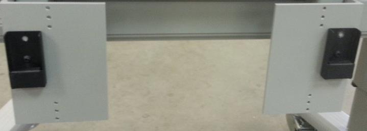
6 d. Once attached the projector plate should look like this. 9. Now mount the Turret head to the stand using the M6 x 20mm Socket Cap Screws Note: if these holes do not line up you will need to loosen the 4 screws on the back of one the braces and move it slightly left or right (See below) 6 P a g e


 7")
7 10. Next attach the CPU Shelf using the M6 x 20mm Socket Cap Screws Note: if these holes do not line up you will need to loosen the screws on the back of one the braces and move it slightly left or right (See Below) 7 P a g e


8 11. Attach the L Brackets at the bottom of the Stand as shown 12. Raise both bracket to the highest point and tighten the screws. 8 P a g e


9 13. Now install the WB Hanger. This will mount in the top holes of the Stand but should be positioned at the bottom (for the Modified Turret use the third hole). 14. Make sure to tighen the Silver button Head Screw on the left and right once the WB hanger is installed 15. Next make sure the Turret assembly and CPU shelf are relatively centered. It does not have to be exact and if it looks center when looking from a distance you are fine. To adjust use the note: instructions under steps 4 and 5. 9 P a g e

10 16. If a Keyboard Tray was ordered attach it now. The 5/16 Hex Head Bolt is a very tight fit. 10 P a g e


11 17. Mount 2 Brackets for the Board on to the WB Hanger. You will use the bottom hole of the first set of holes on the far left and far right. Use the Joro Button head Screws to attach. These are self-tapping holes also. 11 P a g e

12 18. Now mount 2 Brackets for the Board on to the L Brackets at the bottom. You will use the top hole of the middle set of holes. (For the Modified Turret use the top hole of the bottom set of holes). 12 P a g e

13 13 P a g e


14 19. Next attach 4 Hangers to the back of the board (2 on top and 2 on bottom) 20. Position the top brackets so the center of the lip is 6-7/8 from left and right of the inside center of the frame Tighten the bracket screws now 21. Position the bottom brackets so the center of the lip is 21-7/8 from left and right of the inside center of the frame Tighten the bracket screws now 22. Now hang the board on the stand and attach the locking screws at the top. 23. Remove the adjusting block assembly from the mount arm by removing the four screws that secures it to the mount arm. Note: One screw has a spring and flat washer. This will need to be returned to the same location later. 14 P a g e


15 24. Slide the adjusting block assembly from the arm. 25. Remove the projector from the projector box and place it on a stable surface. Take the projector mounting bracket and secure it to the projector as shown below, aligning the screw holes on the projector with the center of the slots on the bracket. 15 P a g e


16 26. Secure it using the four hex head screws in the wall mount box. 27. Slide the adjustment block on the projector as shown below. Slide the adjustment block from right to left, aligning the bracket on the projector with the screw holes. 16 P a g e


17 28. Secure the projector to the adjustment block using the remaining four round head screws provided in the wall mount box. 17 P a g e
 to re-secure it ensuring that the screw with the spring and flat")

18 29. Slide the projector mounting arm onto the mounting plate, taking note to align the tab on the arm with the slot on the plate. Use the screws that you removed when you separated the wall from the arm (see step 9) to re-secure it ensuring that the screw with the spring and flat washer is returned to the original placement. 30. Recheck that the mounting arm is level using the straight edge level from your kit to ensure no shifting has occurred. 31. Attach the tether cable to the mounting arm with the appropriate hardware. 32. Secure the other end of the tether to the top center hole on the Turret head 18 P a g e
.")
19 33. Route your power cable and HDMI Cable 34. Slide the projector, now attached to the adjusting block, onto the mounting arm. Secure it by using the screws that you removed earlier to separate the mounting arm from the adjusting block arm (See Mounting Projector Arm, Step 9). Do not lock the screws as this will need to be done once the projector has been aligned properly. 19 P a g e


20 35. Guide the projector power cable from the back of the board up through the middle of the wall plate. Pull the cable from the back of the wall plate and plug it into the projector. Front View of Cables through Arm on plate 20 P a g e

 Back View of Arm")

21 Top View of Cables going through arm (Note the PC power cable will mount to the stand) Back View of Arm with Cables 36. Do the same for the hdmi and usb cables. 21 P a g e


22 37. Assemble the cable management cover that will go on the side of the projector. 38. Attach the cable management cover to the projector as shown 22 P a g e

23 39. Cover the cables between the projector arm and the board with a length of loom and tighten it at the top and bottom using Velcro strips that have been provided. 23 P a g e

24 40. Route the loom directly behind the board to the computer and cut off excess 41. Connect the USB cable to the board and use remaining Loom and Velcro to secure the cable 42. The power cables will connect to the main power strip on the stand 43. Now installed the computer on the shelf using the double sided sticky Velcro. You will need to cut to size and it will be placed on the bottom out of view. 24 P a g e


25 44. Using the Velcro we want to attach the computer power brick on the stand between the display and the stand. 25 P a g e

26 45. Using the black Velcro organize the main cables from the stand at the surge protector 46. Projector Alignment Steps a. Power on the computer and projector. b. Once the desktop is on the screen, use the following steps to adjust the image as needed until the screen lines up on the board properly: c. Loosen the securing screws at the locations in the image below: 26 P a g e

27 47. Slide the arm forward to adjust the image size until it is large enough to fill the whiteboard. 27 P a g e
28 48. Using the items below, adjust the image until it aligns properly with the whiteboard: 28 P a g e
29 29 P a g e
WB Fastener Kit (ONLY available with G5W & G5W-PRO Models)
") Thank you for purchasing a Pro LIFT G5. The Pro LIFT product line is designed to enhance your interactive whiteboards and projectors or LCD. Please follow all assembly instructions correctly to provide
Thank you for purchasing a Pro LIFT G5. The Pro LIFT product line is designed to enhance your interactive whiteboards and projectors or LCD. Please follow all assembly instructions correctly to provide
ABM International, Inc. Navigator Assembly Manual
 ABM International, Inc. 1 1.0: Parts List Tablet (Qty. 1) Tablet mount (Qty. 1) NOTE: Mount may appear and operate different then image below Control Box (Qty. 1) Motor Power Supply (Qty. 1) 2 X-axis motor
CNC Router Parts PRO Machine Kit Cable Track Installation Instructions
 1 1 X CABLE TRACK TRAYS & BRACKETS The cable track on the side of the system is supported by a metal tray (or multiple trays for longer systems such as a PRO4896). These trays hang from brackets on the
Depending on the size you ordered you will have either 5 Foot sections which will build the 10 Foot frame or 6 Foot sections which will build the 12
 XL Quilting Frame 1 Depending on the size you ordered you will have either 5 Foot sections which will build the 10 Foot frame or 6 Foot sections which will build the 12 Foot frame Printed 2 June 2014 Updated
For additional assistance call
 The following pages will help guide you through the process of assembling your new 48 custom prize wheel. Choose an assembly area with plenty of room to lay your pieces on the floor and also a bench or
+ - 1a. 1b. c. 1d. 1e. Runway Suspended / Surface Cont. Run Installation. 2.0mm DIL DIL Revision - M 23/11/2018 Page 1
 230-240V / 50-60Hz IP20 IK00 + - 2.0mm WARNING - THIS LUMINAIRE MUST BE EARTHED This luminaire has been tested and is manufactured to comply with BS EN 60598 : specification for general requirements and
User Instructions Multiline Otter Scoreboard Caddy Assembly
 List of parts: User Instructions Multiline Otter Scoreboard Caddy Assembly Single Caddy Double Caddy 1 1 Base assembly with attached wheels 2 4 1 1 2 4 4 8 10 20 12 Uprights (60 or 74 aluminum extrusion)
Box Track INSTALLATION INSTRUCTIONS
 Box Track INSTALLATION INSTRUCTIONS BOX TRACK Recommended Tools Level Tape Measure Pencil Drill with 1/8, and 1/4, Drill Bits, Phillips Bit and Slotted Bit Socket Wrench with 9/16 Socket 9/16 and 5/8 Wrench
Range height adjustable assembly
 Table of contents Digital handset operation 3 Height adjustable bench kit 4-5 Cable carrier 6 Ganging tray and ganging rail 7 Height adjustable return frame kit 8 Cable entry pole 9 24 and 30 d worksurfaces
Cable Tray Kit: - Cable Tray - Cable Tray Cover - Power Block Support (x2) Top Support Kit: (x2) - 2 Top Supports. Quantities are per bench
 Top Support Kit: (x2) - 2 Top Supports. Quantities are per bench") Parts Included (per back to back bench) Column Kit: (x2) - 1 LH & 1 RH Column - Control Box - Hand Switch Cable Tray Kit: - Cable Tray - Cable Tray Cover - Power Block Support (x2) Depth Support Kit: -
Parts Included (per back to back bench) Column Kit: (x2) - 1 LH & 1 RH Column - Control Box - Hand Switch Cable Tray Kit: - Cable Tray - Cable Tray Cover - Power Block Support (x2) Depth Support Kit: -
3 wide x 3 deep Video Wall Display Installation Guide
 HoverTrack Series 3 wide x 3 deep Video Wall Display Installation Guide VWD-3X3-X462 This display kit mounts NEC X461UN and X462UNS LCD monitors in a 3 wide by 3 deep landscape configuration. The frame
HQ Pole Upgrade Kit for HQ Adjustable Table and HQ QuilTable Assembly Instructions 1
 HQ Pole Upgrade Kit for HQ Adjustable Table and HQ QuilTable Assembly Instructions QF09775 The pole upgrade kit can be used with or without the QF09700 HQ Precison-Glide track upgrade kit. What s Included
BLT ERGO-E.EAZY
 1 BLT-82493 Adjustable Pneumatic Computer Desk Assembly Instructions Computer Desk Part Drawing Description Qty Part Drawing Description Qty P1 Top Platform 1 EA P11 Cable Management Tray 1 EA P2 Upper
STEP 1 : DESTROYER FRONT BUMPER INSTALL GATHER YOUR TOOLS AND LAY OUT YOUR PARTS... *shorty bumper to show hardware* Tools Required:
 DESTROYER FRONT BUMPER INSTALL JL STEP 1 : GATHER YOUR TOOLS AND LAY OUT YOUR PARTS... Tools Required: - Utility knife - 11/16 Deep socket - Ratchet - 11/16 Crescent wrench - Ratchet Extension - 1/4 socket
v1.0 ASSEMBLY GUIDE Mia Wide Bookcase
 v1.0 ASSEMBLY GUIDE Mia Wide Bookcase Components Upon unpacking your bookcase from it s delivery box, you should have the pieces shown. Follow the steps on the next pages to assemble your new bookcase.
Assembly Instructions 10 X 10 Aluminum Roof Support
 Assembly Instructions 10 X 10 Aluminum Roof Support Aluminum Roof Support Bolt Package 16-5/16 X 2 ¼ SS Bolt 24-5/16 X 1 SS Bolt 40-5/16 SS Nylon Lock Nuts 16-5/16 SS Flat Washers 28-4 ½ Wood Screws 36-1
SmartView Mounting Frame 3 Wide x 3 Deep Video Wall Display Installation Guide
 SmartView Mounting Frame 3 Wide x 3 Deep Video Wall Display Installation Guide WMK-034 This display kit mounts ViewSonic 46 Video Wall displays in a 3 wide by 3 deep landscape configuration. The frame
ASSEMBLY GUIDE. Mia Narrow Bookcase
 ASSEMBLY GUIDE Mia Narrow Bookcase Components: Upon unpacking your bookcase from it s delivery box, you should have the pieces shown. Follow the steps on the next pages to assemble your new bookcase. Step
INSTALLATION GUIDE 8IWBM-EL. phone: (02) fax: (02)
 fax: (02)") INSTALLATION GUIDE 8IWBM-EL www.gilkon.com.au email: sales@gilkon.com.au phone: (02) 99140900 fax: (02) 99140901 CONTENTS 1. DISCLAIMER Page 2 2. WARNINGS & SAFETY INSTRUCTIONS Page 3 3. PACKAGE CONTENTS
INSTALLATION GUIDE 8IWBM-EL www.gilkon.com.au email: sales@gilkon.com.au phone: (02) 99140900 fax: (02) 99140901 CONTENTS 1. DISCLAIMER Page 2 2. WARNINGS & SAFETY INSTRUCTIONS Page 3 3. PACKAGE CONTENTS
INSTALLATION MANUAL PBL-UMP
 INSTALLATION MANUAL PBL-UMP Table of Contents Warning Statements... 4 Parts List... 5 Installation Tools... 5 Features... 7 Projector Preparation... 8 Bracket Installation... 10 Leveling the Mounting Bracket...
PORTABLE ADJUSTABLE BASKETBALL SYSTEM
 Instruction Manual PORTABLE ADJUSTABLE BASKETBALL SYSTEM P A R T S L I S T 5 1/2 and 8 safe play clearance Item Qty Description Item Qty Description A 1 Portable Base Assembly M 4 1/2 Lock Nut B 2 Front
INSTALLATION INSTRUCTIONS 1PC FRONT BUMPER JEEP JK WRANGLER
 INSTALLATION INSTRUCTIONS PARTS LIST: 1 1PC Bumper 2 8mm x 25mm Hex Bolts 1 Bull Nose Hoop 2 8mm x 16mm Hex Bolts 1 Fairlead Mounting Bracket 6 8mm x 24mm x 2mm Flat Washers 8 12mm x 35mm Hex Bolts 4 8mm
MODEL 1703E THE CHAMBERLAIN ARM TM INSTALLATION INSTRUCTIONS To be used in conjunction with the Lift-Master Garage Door Operator Owner's Manual
 MODEL 1703E THE CHAMBERLAIN ARM TM INSTALLATION INSTRUCTIONS To be used in conjunction with the Lift-Master Garage Operator Owner's Before you begin, please read this ENTIRE instruction manual. One- Piece
ABM International, Inc.
 ABM International, Inc. Lightning Stitch required 1 1.0: Parts List head and motor assembly (Qty. 1) Reel stand (Qty. 1) Needle bar frame clamp (Qty. 1) Motor drive (Qty. 1) 2 Cable harness with bracket
SAM. Model: STV-C65 LCD Mobile Visualized Stand Instruction Manual. Weight Capacity: 1251bs / 56.7kg Suits LCD Flat Panel Display: 42"-55" Page 20
 SAM Model: STV-C65 LCD Mobile Visualized Stand Instruction Manual Weight Capacity: 1251bs / 56.7kg Suits LCD Flat Panel Display: 42"-55" 20 Step 6 LCD Mobile Lift Stand Model: STV-C65 Cable management
TITAN2-EDGE Public Access Computer Station Dual Track
 TITAN2-EDGE Public Access Computer Station Dual Track TITAN2-EDGE Rev A 6/17 Model TITAN2-EDGE ASSEMBLY AND ADJUSTMENT TITAN2-EDGE PARTS AND TOOLS PLEASE REVIEW these instructions before beginning the
Installing Brackets to Minimize Distortion in Your SMART Board 685ix Interactive Whiteboard System s Projected Image
 UX60-RFK-685 Installing Brackets to Minimize Distortion in Your SMART Board 685ix Interactive Whiteboard System s Projected Image Follow these instructions to install brackets on your SMART Board 685ix
IMPULSE G2/PULSE STATIC BRIDGE & RETURN MODULE. Drill. Desk Connecting. Outside by fastening the supplied wood screws from the HK-67 kit through the
 PART # 1608990 STATIC BRIDGE & RETURN MODULE 1. This sheet covers the steps to install a static bridge or return module with the FX no hinged access panel back option to a height adjustable freestanding
The Phoenix. Professional Quilting Frame. Copyright January 1, 2016 Jim M. Bagley, GraceWood, Inc (Reproduction Prohibited) Version 2.
 Version 2.") The Phoenix Professional Quilting Frame Copyright January 1, 2016 Jim M. Bagley, GraceWood, Inc (Reproduction Prohibited) Version 2.1 1 The Phoenix Professional Quilting Frame Parts List Box 1...3 Box
The Phoenix Professional Quilting Frame Copyright January 1, 2016 Jim M. Bagley, GraceWood, Inc (Reproduction Prohibited) Version 2.1 1 The Phoenix Professional Quilting Frame Parts List Box 1...3 Box
MANUAL e130. Wallstation
 MANUAL 07.29.13 e130 Wallstation The Enovate Medical e130 Wallstation was designed to set a new standard in quality. Enovate Medical s goal is to provide a wallstation that is ready for years of use,
LCD TV WALL MOUNT INSTALLATION INSTRUCTIONS. DUAL Swing Arm (RFWD-110) WARNING
 WARNING") INSTALLATION INSTRUCTIONS LCD TV WALL MOUNT DUAL Swing Arm (RFWD-110) WARNINGS WARNING WARNING CAUTION CAUTION The maximum weight to be installed on the RFWD wall mount is 40 lbs. (18.1 kg). The RFWD is
INSTALLATION INSTRUCTIONS LCD TV WALL MOUNT DUAL Swing Arm (RFWD-110) WARNINGS WARNING WARNING CAUTION CAUTION The maximum weight to be installed on the RFWD wall mount is 40 lbs. (18.1 kg). The RFWD is
STEP 1 STEP 2 LEVELER KIT OPTION MOBILE CASTER KIT OPTION
 B SERIES INDUSTRIAL BENCHES TOOLS REQUIRED FOR ASSEMBLY Socket set, Open end wrench set, Cordless drill with 3/8" socket bit (Magnetic recommended). BEFORE ASSEMBLY Read through the assembly instructions
e997 Articulating Wall Arm MANUAL IM004-03
 e997 Articulating Wall Arm MANUAL 10.18.16 IM004-03 0 WELCOME The Enovate Medical e997 Articulating Wall Arm was designed to set a new standard in quality. Enovate Medical s goal is to provide a wall arm
RBP-1215B-RX DODGE RAM QUAD CAB RX3
 RBP-1215B-RX3 2002-2017 DODGE RAM 15-3500 QUAD CAB RX3 Passenger side RX-3 Side Step Drill Template Passenger side rear Modular Bracket (6) L Support Brackets Driver side rear Modular Bracket Driver side
Copyright Black Box Corporation. All rights reserved Park Drive Lawrence, PA Fax
 Copyright 2004. Black Box Corporation. All rights reserved. 1000 Park Drive Lawrence, PA 15055-1018 724-746-5500 Fax 724-746-0746 JANUARY 2004 RF500A RF507A RF514A RF521A RF501A RF508A RF515A RF522A RF502A
MPA-9000 Universal Ceiling Projector Mount Kit
 I N S T R U C T I O N M A N U A L Universal Ceiling Projector Mount Kit The Universal Ceiling Projector Mount provides a unique, simplified method of ceiling mounting your inverted projector. This low
INSTALLATION INSTRUCTIONS
 INSTALLATION INSTRUCTIONS PARTS REQUIRED Single QuickStand Lite Parts A (1) Lower Arm A B C D B (1) Upper Arm C (1) Base D (1) Base Plate E (1) M8 Dynamic Arm Long F (1) Clamp Bracket G H (1) VESA Plate
RANGE DIGITAL HANDSET OPERATION. 1. Panel. 2. Initialization Procedure. 3. Move Up & Down. 4. Set Memory Positions. 5. Move to the Memorized Positions
 INSTRUCTION SHEET #2577INS PART #1730534 DIGITAL HANDSET OPERATION OPERATION INSTRUCTIONS 1. Panel 1 Button: Preset 1 2 Button: Preset 2 3 Button: Preset 3 S Button: Select Display: Reads in 1 / 2 " Increments
INSTALLATION MANUAL PBC-UMS
 INSTALLATION MANUAL. PBC-UMS Premier Mounts 3130 E. Miraloma Avenue Anaheim, CA 92806 Phone: (800) 368-9700 Fax: (800) 832-4888 mounts@mounts.com www.mounts.com Rev. 01 PBL-110 Projector Mount Page 2 Installation
PRS Retro Z-Axis Installation
 PRS Retro Z-Axis Installation Page -1- PRS Retro Z-Axis Installation This document is a guide to installing the PRS Retro Z-axis on early ShopBot models. It describes installation for PR models with PK299
Assembly Instructions 10 X 10 Aluminum Frame Building
 Assembly Instructions 10 X 10 Aluminum Frame Building 27 97 9 8 47 36 74 52 10 10 X 10 Square Building W/ Dome Includes: The Steel Entry Door with a Dead Bolt Lock assembly and Aluminum Door Frame. Metal
LCD MONITOR/TV WALL MOUNT
 INSTALLATION INSTRUCTIONS LCD MONITOR/TV WALL MOUNT DUAL DESK CLAMP (RFCD-110) S CAUTION CAUTION A alerts you to the possibility of serious injury or death if you do not follow the instructions. A CAUTION
PERSONAL RECORD KEEPING
 2 P R O 3 7 0 A s s e m b l y i n s t r u c t i o n s PERSONAL RECORD KEEPING Tip: Record the serial numbers of your Octane Fitness elliptical in the spaces below. This will make it easier for you to obtain
MAG-CONV Basic, 48, 48R & Midline Front Mount
 Parts Required: Tools Used: Mag Wheels Brakes Brake Rods Mounting Bracket Anti Tippers 7/16" Wrench Screw Driver Rubber Mallet 5/8 Wrench 5mm Allen Wrench Step Execution Figures 1 Remove front 5" total
Legacy Woodworking Machinery a division of Phantom Engineering. The Legacy CNC. Assembly Manual
 Legacy Woodworking Machinery a division of Phantom Engineering The Legacy CNC Assembly Manual New Orientation of the Legacy Step one: Re-orientation of the machine Remove the X-axis screw and supports.
Projector Flush Mount
 Projector Flush Mount ABtUS SIGAPORE PTE LTD Model: AV819 www.abtussingapore.com Patent Pending Revision 21/05/2012 ABtUS SINGAPORE PTE LTD www.abtussingapore.com User Operation Guide IMPORTANT NOTES Thank
Motorized or Crank Operated Fortress Zipper Track Shade with Housing and Side Track Installation Instructions
 Motorized or Crank Operated Fortress Zipper Track Shade with Housing and Side Track Installation Instructions Tools Needed Drill 3/8 Metal Drill Bit ¼ Masonry Drill Bit Measuring Tape Pencil 4 Level Phillips
Office Partitions WARNING. Assembly Instructions. Customer Service A S S E M B LY HARDWARE H1 H2 H3 H4 H5 H8 H9 H10 H11 H12
 Customer Service 1-800-645-2986 Assembly Instructions WARNING In order to prevent structural failure, instability, t i p - o v e r, and/or serious injury, please follow i n s t ructions care f u l l y.
OXYGEN INSTALLATION. Revision date
 12345 1 Hardware List 12345 Flat head wood screw #9 x 7/8 long with #2 Phillips drive, silver Used to attach surfaces and end panels Hex set screw ½-13 x 2 long with 1/4 hex drive, black Used on Legs Hex
Fixed Wall Arm. Installation Guide. Part number Rev E 2012 PolyVision Corporation All rights reserved
 Fixed Wall Arm Installation Guide Part number 2002003-001 Rev E 2012 PolyVision Corporation All rights reserved Table of contents Important Safety Instructions... 3 Overview... 4 Important considerations...
Passenger/Right Front Mounting Bracket
 PARTS LIST: 1 Driver side running board 1 8mm Insert Installation Tool 1 Passenger side running board 4 10-1.50mm x 35mm Hex Bolt 1 Driver 10 10mm x 24mm OD x 2.2mm Flat Washer 1 Passenger 6 10mm Lock
The Bowflex Revolution XP Home Gym Assembly Instructions. P/N: Rev ( /0 )
") P/N: 001-7057 Rev ( /0 ) The Bowflex Revolution XP Home Gym Assembly Instructions 2 Table of Contents Before You Start... 2 Tools You Will Need / Hardware Contents... 3 Box Contents... 6 Assembling Your
P/N: 001-7057 Rev ( /0 ) The Bowflex Revolution XP Home Gym Assembly Instructions 2 Table of Contents Before You Start... 2 Tools You Will Need / Hardware Contents... 3 Box Contents... 6 Assembling Your
Installation Instruction
 Tools Needed for Assembly Stud finder (for wood stud wall) Pencil Mark Electric drill Wood Stud Wall Installation Step 1. Locate the Wood Studs Installation Instruction Drill bit (for wood stud wall) Masonry
Flat Panel Mobile Cart and Accessories
 INSTALLATION MANUAL Flat Panel Mobile Cart and Accessories Optional Accessories TCH01 TDV01 TLP01 TCR01 Note: The accessories are not standard. The accessories will be selected according to user requirement.
KWIK-KIT KK-S INSTALLATION INSTRUCTION PACKAGE
 KWIK-KIT KK-S-120-02 INSTALLATION INSTRUCTION PACKAGE INSTALLATION INSTRUCTIONS HAVIS KWIK-KIT KK-S-120-02 2002-2007 DODGE/FREIGHTLINER SPRINTER VAN PLEASE READ COMPLETE INSTRUCTIONS PRIOR TO INSTALLATION
ēno one Adjustable Wall Mount and Adjustable Mobile Stand Installation Guide
 Installation Guide Part number 2002105-001 Rev B 2011 PolyVision Corporation All rights reserved Table of contents Overview... 3 Important considerations... 3 Adjustable Wall Mount considerations... 3
Mounting a BalanceBox 400 to a brick wall
 Unpack the BalanceBox 400 and remove the Wall frame cover and its bag of screws. Slide the cover out at the top. NOTE: the cover is NOT included with the BalanceBox 400H LOCK SCREW HOLE MOBILE STAND MOUNTING
 Menu Board Tilt or Fixed Mount Installation Instructions MDS1T-200, MDS1T-300, MDS1T-400 MDS2T-200, MDS2T-300, MDS2T-400 MDS3T-200, MDS3T-300, MDS3T-400 MDS4T-200, MDS4T-300, MDS4T-400 MDS5T-200, MDS5T-300,
Mounting Instructions For 3-Piece Namur Style Mounting Bracket To 2-Way 60 Series Valves
 Mounting Instructions For 3-Piece Namur Style Mounting Bracket To 2-Way 60 Series Valves NOTE: These instructions apply only to 60 series ball valves with bodies containing external mounting nibs. External
EmagiKit. Privacy Pod Plus. Quiet. Easy. Affordable. INSTRUCTIONS ASSEMBLY
 EmagiKit Privacy Pod Plus Quiet. Easy. Affordable. INSTRUCTIONS ASSEMBLY DIMENSIONS AND COMPONENTS 47 47 Ceiling Unit 2-B 2-L 2-R Glass Door Corner Trim Door Handle 90 Adjustable Height Work Surface 1-B
WARNING: Prior to installation, turn the power off to the vending machine and unplug it from its power source. Also, make sure to level the machine.
 Installation of Gum and Mint Tray for National 147, 157, 167 Important Note: Please read all instructions thoroughly before continuing with installation of kit. If you are having problems installing the
Mirage Installation Manual
 Mirage Installation Manual General Information This installation manual provides necessary information for the safe installation of the Mirage product. WARNING: Failure to follow the instructions in this
Replacing the Reciprocator on the SWF Compact Series Machine (601C and 1201C)
") Follow the instructions below to replace the reciprocator in the SWF Compact series machines. The tools required can be found in the tool kit that came with the machine. Preparation 1. First, place the
Follow the instructions below to replace the reciprocator in the SWF Compact series machines. The tools required can be found in the tool kit that came with the machine. Preparation 1. First, place the
WOLF PUP LOOM TM & WOLF PUP LT LOOM TM
 WOLF PUP LOOM TM & WOLF PUP LT LOOM TM Assembly Instructions FL3000 FL3006 FL3009 WOLF PUP WOLF PUP LT Find out more at schachtspindle.com Schacht Spindle Company 6101 Ben Place Boulder, CO 80301 p. 303.442.3212
Star Trac Turbo Trainer Assembly & Setup
 Star Trac Turbo Trainer Use the following procedures to unpack and assemble your Turbo Trainer manufactured by Star Trac. UNPACKING AND PARTS LIST Position the shipping carton so the Heavy End logo is
Otter Pro XT Cottage Installation and Set-Up Instructions
 Otter Pro XT Cottage Installation and Set-Up Instructions Otter Pro XT Cottage Fits Small Ultra-Wide Otter Pro and Otter II Sled Only Parts Identification and Check List MODEL NUMBERS: Complete Pkg Pro
INSTALLATION INSTRUCTIONS KK-K9-F14-K K9 KIT FOR FORD EXPEDITION
 INSTALLATION INSTRUCTIONS KK-K9-F14-K-32 32 K9 KIT FOR 2003-2016 FORD EXPEDITION TOOLS REQUIRED: Power Drill Drill Bit Set Standard & Metric Socket Sets Phillips Screw Driver Open End Wrench Set Wire Cutters
INSTALL INSTRUCTIONS WELCOME TO THE NEWAGE PERFORMANCE CABINETRY SERIES NEWAGE STEEL WELDED CABINETRY
 NEWAGE STEEL WELDED CABINETRY WELCOME TO THE NEWAGE PERFORMANCE CABINETRY SERIES ALL CABINETS MUST BE MOUNTED TO STUDS ON A SECURE WALL, AS PER THESE INSTRUCTIONS. FAILURE TO DO SO MAY RESULT IN SERIOUS
Assembly Instructions Nevins Phone Booth
 Assembly Instructions Nevins Phone Booth Included Hardware Tools Required supplied by installer Drill & Bit Bolt A - (16) 1/4-20 x 1-1/2 hex head Bolt B - (20) 1/4-20 x 2-1/2 phillips head Screw 1 - (24)
Baby Grande or Grande Crank Shade with Cables and Housing Installation Instructions
 Baby Grande or Grande Crank Shade with Cables and Housing Installation Instructions Tools Needed Drill 3/8 Metal Drill Bit Screwdriver (Flat & Phillips) Measuring Tape Pencil 4 Level Plumb Line ¼ Masonry
7878 K940. Checkpoint Antenna. Kit Instructions. Issue B
 7878 K940 Checkpoint Antenna Kit Instructions Issue B Revision Record Issue Date Remarks A July 7, 2009 First issue B Nov2013 Revised the Checkpoint installation procedures for 7878 and 7874 scanners Added
BX2173 Installation Instructions Ford Focus (including the 2.3L engine) 2003 Ford Focus SVT
 2003 Ford Focus SVT") BX2173 Installation Instructions 2000-04 Ford Focus (including the 2.3L engine) 2003 Ford Focus SVT Serial No. The front fascia, coolant line bracket and anti-pollution devices are removed for baseplate
BX2173 Installation Instructions 2000-04 Ford Focus (including the 2.3L engine) 2003 Ford Focus SVT Serial No. The front fascia, coolant line bracket and anti-pollution devices are removed for baseplate
APS Small Seeds Box Assembly Instructions
 APS Small Seeds Box Assembly Instructions For APS15 Series All Purpose Seeder Manual No. 313-473M Before You Start! When you see this symbol, the subsequent instructions and warnings are serious - follow
How to assemble PIANO
 Before you begin, make sure there is a clean, carpeted floor to work on, or use clean cardboard or blankets to protect the furniture surfaces during the assembly process. Unpack and Identify the parts
Machine Quilting Frame assembly, and instruction manual
 Machine Quilting Frame assembly, and instruction manual Table of Contents Parts List................. Pg. 2 Step 1 - Legs............... Pg. 4 Step 2 - Lower Leg Brace....... Pg. 5 Step 3 - Frame Ends..........
EPPA2-KIT DUAL MONITOR ARM CONVERSION
 EPPA2-KIT DUAL MONITOR ARM CONVERSION EPPA2-KIT Rev A 10/17 Model EPPA2-KIT-XXX ASSEMBLY AND ADJUSTMENT EPPA2-KIT PARTS AND TOOLS PLEASE REVIEW these instructions before beginning the assembly and adjustment
Installation and Assembly - Universal Articulating Swivel Double-Arm for 42" - 60" Plasma Screens
 Installation and Assembly - Universal Articulating Swivel Double-Arm for 42" - 60" Plasma Screens Models: PLAV 70-UNL, PLAV 70-UNL-S PLAV 70-UNLP, PLAV 70-UNLP-S R This product is UL Listed. It must be
RC4WD Diablo V2 Instruction Manual
 Version 1.1 RC4WD Diablo V2 Instruction Manual Thank you for your purchase. Welcome to the RC4WD family. This kit is a combination of many specially engineered and manufactured parts. Enjoy your build.
Gared Pro Portable Backstop
 Models: 5016, 5017, & 5018 Installation, Operation and Maintenance Instructions Please read all instructions before attempting installation or operation of these units PUBLICATION NO. 551754436 SAVE THESE
INSTALLATION INSTRUCTIONS HEAVY DUTY TILT WALL MOUNT Model: PPH-2000
 INSTALLATION INSTRUCTIONS HEAVY DUTY TILT WALL MOUNT Model: PPH-2000 Specifications: Accomodates Akira and Orion 84" displays without interface bracket; accomodates other large flat panel displays with
Oxford Stalls Installation Instructions
 Oxford Stalls Installation Instructions RAMM Horse Fencing and Stalls 13150 Airport Hwy. Swanton, OH 43558-9615 1-800-434-8456 Rev. 8/15/17 Before You Start Typical stall sizes are 10 x 10, 12 x 12 or
Fortress Fe Posts must always be secured to the deck framing. Fortress Fe Posts should never be attached to only the deck boards.
 Installation Instructions for FortressCable H-Series Stair Panels with Simplified Stair Bracket SSB-05 and Fe Posts It is the responsibility of the installer to meet all code and safety requirements, and
PERSONAL RECORD KEEPING
 PRO3700 2 P R O 3 7 0 0 A s s e m b l y i n s t r u c t i o n s PERSONAL RECORD KEEPING Tip: Record the serial numbers of your Octane Fitness elliptical in the spaces below. This will make it easier for
Install Instructions. NewAge Steel Welded Tall Locker
 Kit Contains Full Width Adjustable Steel Shelves (4) Height-Adjustable Steel Leveling Legs (4) Aluminum Door Trim (2) 2.5 x ¼ Cabinet Mounting Lag Bolts (4) Large Zinc Plated Mounting Washers (4) 5/8 x
(2) Plastic Plugs (2) Frame Bracket. Spacers. License Plate Bracket. (2) 12mm Single Bolt Plates. (2) 12mm Double Bolt Plates
 Plastic Plugs (2) Frame Bracket. Spacers. License Plate Bracket. (2) 12mm Single Bolt Plates. (2) 12mm Double Bolt Plates") LDB-CSIL26-FB PARTS LIST: 1 LD1 Bumper Assembly 10 12mm Hex Nuts 1 Driver/left Frame Mounting 6 10-1.5mm x 35mm Hex Bolts 1 Passenger/right Frame Mounting 12 10mm x 27mm OD x 3mm Flat Washers 2 Spacers
LDB-CSIL26-FB PARTS LIST: 1 LD1 Bumper Assembly 10 12mm Hex Nuts 1 Driver/left Frame Mounting 6 10-1.5mm x 35mm Hex Bolts 1 Passenger/right Frame Mounting 12 10mm x 27mm OD x 3mm Flat Washers 2 Spacers
Tools Required: - Utility knife - 11/16 Deep socket - Ratchet - 11/16 Crescent wrench - Ratchet Extension - 1/4 socket - Electrical tape
 DESTROYER FRONT BUMPER INSTALL JL STEP 1 : GATHER YOUR TOOLS AND LAY OUT YOUR PARTS... Tools Required: - Utility knife - 11/16 Deep socket - Ratchet - 11/16 Crescent wrench - Ratchet Extension - 1/4 socket
IMPULSE G2/PULSE STATIC BRIDGE & RETURN MODULE. Drill. Desk Connecting. Outside by fastening the supplied wood screws from the HK-67 kit through the
 PART # 1608990 STATIC BRIDGE & RETURN MODULE 1. This sheet covers the steps to install a static bridge or return module with the FX no hinged access panel back option to a height adjustable freestanding
INSTALLATION INSTRUCTIONS Flat Panel Static Wall Mount Model: GSM-111
 INSTALLATION INSTRUCTIONS Flat Panel Static Wall Mount Model: GSM-111 The GSM-111 static wall mount fits most 23" to 30" displays. The GSM-111 is designed to adapt to VESA 200mm/ 100mm compliant displays.
Calf-Tel Pen System Assembly Instructions
 Calf-Tel Pen System Assembly Instructions (Instructions work for 4, 6, and the 7 Pen Systems) 1 ASSEMBLY OF PEN FRONT AND WALLS START THE ASSEMBLY BY LINING UP THE TWO UNI-DIRECTIONAL ARROWS IN THE TOP,
Baby Grande or Grande Crank Shade with Cables and Housing Installation Instructions
 Baby Grande or Grande Crank Shade with Cables and Housing Installation Instructions Tools Needed Drill 3/8 Metal Drill Bit Screwdriver (Flat & Phillips) Measuring Tape Pencil 4 Level Plumb Line ¼ Masonry
Step 1: The larger tower box contains the tower machine, a set of Silver 100 Lid Keys, and a set of Black 002 Coin Box Keys
 2 3 Step 1: Each tower is shipped as two boxes the large tower box and the smaller stand box. Open each of the boxes and inventory each of the parts before starting assembly to ensure all parts have arrived.
PRS X-Axis E-Chain Installation For Tools with a 12 Z-Axis
 888-680-4466 ShopBotTools.com PRS X-Axis E-Chain Installation For Tools with a 12 Z-Axis This kit is compatible with PRS Shopbots that have an X-axis cutting area of 96 to 144. It is not immediately compatible
Please read BOTH these Installation Instructions and the General Instructions prior to installing or operating this equipment.
 Serial Number BX3620 Please read BOTH these and the General Instructions prior to installing or operating this equipment. 1. Blue Ox towing products and accessories are intended to be installed by Blue
INSTRUCTION BOOKLET #34. For Wallbed models: KING SIZE SIERRA WITH STORAGE HEADBOARD
 For Wallbed models: KING SIZE SIERRA WITH STORAGE HEADBOARD INSTRUCTION BOOKLET #34 WARNING! ALL MURPHY/WALLBED SYSTEMS CONTAIN STORED ENERGY. FAILURE TO USE AND FOLLOW THESE INSTRUCTIONS DURING THE INSTALLATION
Installing The Aliens Extermination Deluxe 50" Cabinet with Sintra Marquee
 Installing The Aliens Extermination Deluxe 50" Cabinet with Sintra Marquee Document Part #: 040-0262-01 This document describes how to install The Aliens Extermination Deluxe Cabinet with Sintra Marquee
Heavy Duty I-Beam Trolley
 Heavy Duty I-Beam Trolley ASSEMBLY INSTRUCTIONS I-BEAM TROLLEY Recommended Tools Level Tape Measure Pencil Drill with 1/8, 1/4, and 3/8, Drill Bits and Phillips Bit Socket Wrench with 9/16 Socket I-BEAM
Heavy-Duty Bypass Track System
 Heavy-Duty Bypass Track System Please Note: This track system must be installed with the screws going into a solid surface such as studs or a header. Due to the spacing of the holes on these Brackets,
Gared Pro-S Portable Backstop
 Models: 9616 & 9618 Installation, Operation and Maintenance Instructions Please read all instructions before attempting installation or operation of these units SAVE THESE INSTRUCTIONS FOR FUTURE USE PUBLICATION
Tilting & Swiveling Plasma/LCD Flat Panel Wall Mount Installation Guide Model: A380SM
 Tilting & Swiveling Plasma/LCD Flat Panel Wall Mount Installation Guide Model: A380SM Easy installation Built-in level for easy positioning Corrective leveling adjustments after installation Forward /
FIRST TEAM SPORTS, INC.
 FIRST TEAM SPORTS, INC. INVADER EZ-CRANK PORTABLE BASKETBALL GOAL ASSEMBLY INSTRUCTIONS Revised - 08/04/10 BILL OF MATERIALS (1) BASE TANK (1) BACKBOARD MOUNT (2) 5/16 X ¾ HEX BOLT (1) LOWER POST (2) SPRING