RC4WD Diablo V2 Instruction Manual
|
|
|
- Ambrose Turner
- 5 years ago
- Views:
Transcription

1 Version 1.1 RC4WD Diablo V2 Instruction Manual Thank you for your purchase. Welcome to the RC4WD family. This kit is a combination of many specially engineered and manufactured parts. Enjoy your build. This is a complete instruction manual for the Diablo truck kit. We have tried to detail as many things in the build process as possible. Since the kit has so many options available it is hard to cover all of them. This manual covers the basic kit. If for some reason you don t find enough detail here, or you are having issues with your build please visit RC4WD Diablo forum here. You will need to have a few things for this build. Metric Hex Wrenches Regular Wrenches, or Nut Drivers Pliers Monster Lube RC4WD #X-0317 Blue Thread locker The first thing you will want to do is unpack your truck kit. Be careful with the parts when unpacking and make sure to inventory all your items. Skid plate and axles not shown in photo. Some items may have changed, photo is for example only. This doesn t represent what you have received, as the kits are custom built.
2 When you build this kit you will want to use some Blue thread locker on the metal to metal parts. The included nuts have nylon inserts to prevent them from backing off, but all other metal to metal surfaces will stay in place better with the thread locker. Anytime you see an *, this notes the need for thread locker. (please be sure to get blue thread locker, it is removable.) Hardware Listing (12) M3 Nylock nut (2) Black Motor Screws (12) M3 X 16mm SHCS (30) M3 X 8mm SHCS Miscellaneous parts listing (1) 89mm Steering Link (4) Body posts (4) Curved rod ends (4) 79mm Lower Links (4) M3 X 16mm SSS (28) M3 conical washers (6) M3 X 12mm SHCS (4) M3 X 25mm SHCS (12) M3 X 20mm SSS (6) M3 X 10mm SHCS (4) (1) (4) (4) (1) 33mm Steering link (12) Black straight Rod ends (2) 3 link Y s (2) Single point 3 link mount 70mm long Silver links Bottom Skid Velcro Straps 60mm Upper Links Additional Hardware Included with R2D II Items included with the R2 Dig (1) 8t 32 pitch pinion gear (1) Set screw for pinion (1) Optional spring (2) Motor screws Items included for the Sideway Servo Mount (1) (1) (1) (3) 40mm Link M3 short rod ends M3 X 10 SSS Different size dig sliders (1) (5) (5) (7) Two stage collar M3 Nylock nuts M3 X 12mm SHCS M3 Flat washers (1) M3 Long rod end (1) M3 X 25mm SHCS (1) M3 X 20 SSS Misc. other set screws Assembly Steps Step 1. Motor Installation Items needed R2 Transmission (1) Pinion set screw (2) Motor screws 8t 32 pitch pinion gear Now you can install the motor into the R2 tranny. Use an Allen wrench to install the set screw into the Pinion gear supplied. Then install the Pinion gear onto the motor and tighten the set screw. If the motor has the flat on the shaft, make sure and align the set screw up with the flat of the motor shaft.


3 Next install the motor into the tranny on the side with the small hole. Using the black motor screws supplied insert the screws thru the holes in the tranny then into the motor. Make sure to tighten the screws only part way. You will want to align the pinion and R2 gear mesh, then tighten the screws all the way down. Proper gear mesh can make the R2D gears last a long time, and will reduce gear noise. If you set the lash to tight it will wear the gears and be very loud. The mesh in the photo is just about right. You will want to use some Monster Lube to lubricate the gears. More lube is better. At this point the shafts will be almost impossible to turn by hand. Step 2. Dig unit installation Here we will add the servo and linkage to the R2D tranny. You will need to get your servo and R2D tranny for this assembly. A. Sideway servo mount Items needed Sideway servo mount


4 Remove the two screws on the R2D that are above and below the front hole. With these screws removed you can install the servo mount like shown in this photo. Reinstall the screws to secure the servo mount. * B. Servo installation Items needed (4) M3 x 12mm SHCS (4) M3 flat washer (4) M3 Nylock nuts For this step you will need a servo with at least 60 oz of torque, or more. You will also want a servo arm that has some holes close to the center of the arm mount. Install the servo with the mounts to the back of the servo mount like shown in the photo below. Use the 4 screws, washers, and nuts to secure the servo.


 M3 Flat washers onto the M3 X 25mm SHCS then install into the short link.")
5 C. Linkage assembly Items needed (1) short M3 rod end (1) long M3 rod end (1) M3 X 10mm SSS (1) M3 X 20mm SSS (1) Short link Assemble like shown in the second photo. * D. Link install onto servo and R2D Items needed M3 X 12mm SHSC M3 Nylock nut Special two stage collar M3 X 25mm SHCS (3) M3 Flat washer Large dig collar In some cases your set-up might require you to change a few things. There are plenty of additional parts in the bag for extra set-ups. You can see in the photo below that you need to insert (2) M3 Flat washers onto the M3 X 25mm SHCS then install into the short link. Install the end of the screw into the two stage collar and add another M3 flat washer. Now thread the screw into the large dig collar. Slide the dig collar onto the dig shaft coming out the back of the R2D and tighten. * Use the M3 X 12mm SHCS to install the

 Curved rod ends (8) M3 Long rod ends (2) 3 link Y s A.")
 black long straight M3 rod ends, (8) M3 X 20mm SSS, and (4) 79mm long links.")
6 other end of the link onto the servo arm. Use the nut to secure the SHCS and link to the servo arm. * Additional tips Be careful when using the dig collars provided that you don t tighten the screws to much, as they may strip. Using a Dremel and a grinding bit you could apply a flat spot on the dig shaft. Check your alignment before performing any modifications. Step 3. Link Assembly A. Items needed (4) Curved rod ends (8) M3 Long rod ends (2) 3 link Y s A. (4) M3 X 16mm SSS (8) M3 X 20mm SSS (4) 60mm Upper Links (4) 79mm Lower Links You can now assemble the links. The lower links are first. Pull out (8) black long straight M3 rod ends, (8) M3 X 20mm SSS, and (4) 79mm long links. You can insert the set screws into the rod ends and then assemble into each end of the link. * They should look like the rod in the top of the first photo.
 Black curved M3 Rod ends, (8) M3 X 16mm SSS, and (4) 60mm long links.")

 89mm Steering Link (1) 33mm Steering Link Onto the steering links. These are just as easy to assemble.")
7 The upper links use the curved rod ends, and the 3 link Y s. Get (4) Black curved M3 Rod ends, (8) M3 X 16mm SSS, and (4) 60mm long links. You can insert the set screws into the straight rod ends, then into the curved rod ends. * Now install the links into the 3 link Y s. * They should look like the link in the third photo. B. Items needed (4) M3 Long rod ends (4) M3 X 20mm SSS B. (1) 89mm Steering Link (1) 33mm Steering Link Onto the steering links. These are just as easy to assemble. Use the Black Long straight M3 Rod ends, the M3 X 20mm SSS, and the Steering links. You can insert the set screws into the rod ends and then assemble into each end of the link. * They should look like the rods in the second photo.


8 Step 4. Shock Fluid You can now fill your shocks with fluid. This is a simple thing. You can remove the shock cap and put your favorite shock fluid into the shock. Make sure that all the air and air bubbles are out of the shocks before you reinstall the cap. Make sure the shocks are not locked and then set them aside for final assembly. Additional Tip. These shocks typically work best with a small amount of fluid to help them move. Most that use them do not fill them with fluid. This is up to the user. Step 5. Axle Lubrication Lubrication of the axle gears is a very important step in the assembly of your kit. Remove the screws holding the cover onto the axles (like in the second photo). Use some Monster Lube on the main gear, and reinstall the cover. Be careful not to tighten the screws to much, you can strip the plastic.
 Step 6.")
 M3 X 16mm SHCS (4) upper part")


9 (There are washers included with the axles. Use these as shims if needed) Step 6. Axle Servo 4 Link mount assembly Items needed (4) M3 X 12mm SHCS (4) M3 X 16mm SHCS (4) upper part of the 4 link mounts (2) servo/link mounts (2) Single point 3 link mount You can install each lower 4 link mount to the sides of the servo mounts. Use the M3 X 12mm SHCS in the back hole and the M3 X 16mm in the front hole. * Make sure that the link mounts are all facing the same way like in the second photo. Once these are installed on the axles they can t be changed unless removed from the axles. Now you can remove the old 4 link mount and install the new Single point 3 link mount. Remove the screws holding the 4 link in. Install the 3 link in the same location with the same screws. * Step 7. Chassis assembly

 M3 X 8mm")


10 Items needed (12) M3 X 8mm SHCS (4) M3 nylock nuts R2D transmission (2) Diablo side plates Lower skid plate You can install one side of the Diablo chassis at a time using (4) M3 X 8mm SHCS on each side. * It only lines up one way. Before installing the other chassis plate, install the lower skid with (2) M3 X 8mm SHCS and (2) M3 nylock nuts. Once again, the chassis only allows the skid in one spot for mounting. Now you can install the other Diablo chassis plate the same way you did the first using the remaining screws. * Step 8. 4 Link Placement onto the Diablo chassis Here you can install the front and rear 4 links to the Diablo Chassis. This will require several pieces of hardware.


 Now use the M3 X 16mm SHCS and install the rest of the upper links.")
11 A. Items needed (3) M3 X 16mm SHCS (1) M3 X 12mm SHCS A. (4) M3 conical washers (4) M3 nylock nuts. Install the upper links first. In this step it may be easiest to turn the chassis over on its top. We will be using the 3 link mounts. When sliding the curved rod ends onto the Diablo chassis you may find it hard to install. This will take a little time and patience, but it is meant to be tight. Install the only M3 X 12mm SHCS into one of the curved rod ends. Then install a M3 conical washer with the beveled face toward the rod end. Then insert the screw into the first hole on the motor side like in the second photo. This will go on the outside of the chassis. Install the M3 nylock nut to secure the link. (Add a little thread locker to the nut before installing. This will help secure the bolt.) Now use the M3 X 16mm SHCS and install the rest of the upper links. Use a conical washer on each one making sure the bevel is toward the rod end. Then use the M3 nylock nuts to secure the links. B. Items Needed (4) M3 X 20mm SHCS (8) M3 conical washers

 Tip. If the links are to close to the skid plate, you may have to bend the plate a small amount. Step 9.")

12 A. Now install the lower links to the Diablo chassis. Use the remaining 4 long links for this step. Insert a M3 X 20mm SHCS into the chassis were marked in the first photo. Then insert a M3 conical washer with the bevel facing to the screws end. Slide the rod end onto the screw and then another conical washer with bevel facing the link end and then secure with a M3 nylock nut. Do the same for the other 3 links. (See the third photo) Tip. If the links are to close to the skid plate, you may have to bend the plate a small amount. Step 9. Shock mounting Items Needed (2) 70mm links (4) M3 X 16mm SHCS (4) M3 conical washers (4) Dual stage shocks Now you can install the shocks to the Diablo chassis. The 2 links will run in-between the chassis plates. Insert the M3 X 16mm SHCS into the top of the shock body, then install a M3 conical washer with the beveled edge toward the shock. Insert the screw into the second hole like shown in the photo below and tighten into the support shaft. * Repeat this step 3 more times using the same screws and into the same holes.
 M3 X 25mm SHCS B.")

13 Step Link Placement/Shocks onto servo mounts Now install the front and rear 4 links to the servo mounts. A Items needed (2) M3 X 10mm SHCS A. Install the upper 3 link first. Insert a M3 X 10mm SHCS into the single point 3 link mount and then into the 3 link Y mount. * Repeat this step for the other end. B. Items Needed (4) M3 X 25mm SHCS B. (12) M3 conical washers The lower links and shocks can be mounted to the lower 4 link mounts. Insert a M3 X 25mm SHCS into the end of the shock bottom. Then slide a M3 conical washer onto the screw with the beveled edge facing the shock end. Install another conical washer on the screw with the bevel facing the screw end. Now install the lower rod end onto the screw and slide another conical washer onto the screw with the beveled facing the rod end. Now insert the screw into the end hole of the lower link mount. *
 M3 X 8mm SHCS (4) lower 4 link axle mount")


14 You should have something that looks like this. Step 11. Installation of the axles Items Needed (8) M3 X 8mm SHCS (4) lower 4 link axle mount The lower 4 link mounts have a small lip inside them shown in the first photo. The lip lines up with a groove on the bottom of the axles. Put the axle up to the servo mount making sure the grooves are facing down. Install the lower mount using the M3 X 8mm SHCS. * Repeat this step until you have all the screws secured for the lower link mounts and your axles are installed. *
 M3 X 8mm SHCS (4)")


15 Step 12. Servo and Servo Mount Install Items Needed (2) M3 X 8mm SHCS (4) M3 X 10mm SHCS (4) M3 nylock nuts Line the servo mounts up similar to the photo below. Use the M3 X 8mm SHCS to secure the mount. This may require some repositioning once you install the servo and steering links. You may want to add two small regular nuts too the screws (not included) To install your servo you can use the M3 X 10mm SHCS, and nylock nuts like shown below. (you may choose to use some flat washers here, not provided in the kit)


16 Step 13. Installation of the Punisher shaft You can install the Punisher shafts that were included with your kit. These already have the set screws installed into them. You may want to use a small amount of thread locker on the set screws when installing the shafts. The female shaft needs to be installed to the axle. While the male side attaches to the transmission. Please be sure that the set screw is secured to the flat spot on the pinion shaft sticking out from both the axles and the transmission. The rear shaft will need the Pinion extension installed. This allows the punisher shaft to fir when using the large dig collar. Front Rear
 M3 X 16mm SHCS")


17 Step 14. Installing the Front Steering links Items Needed (1) M3 X 16mm SHCS (1) M3 X 12mm SHCS You can install the steering links you made earlier. Use the M3 X 16mm SHCS into one end of the short rod end and then into the long rod end. You can now install the screw into the steering knuckle like shown in the first photo below. Use the M3 X 12mm SHCS to secure the other end of the long link to the opposite steering knuckle. (Use your own hardware to attach the short link to your servo arm) Step 15. Bracing and body mounts Items Needed (8) M3 X 8mm SHCS


18 You can use the additional 70mm links to support the Diablo chassis. Use the M3 X 8mm SHCS to secure the links. * You can see the additional link in the photo below. Where you place these are up to you. The body mounts included in the kit uses the M3 X 8mm SHCS. * You may install them anywhere you like. Step 17. Wheel and Tire Installation Make sure when mounting the tires on any wheel that you look at the tread pattern and make sure that when the wheels are installed that each are facing the right direction. It will take a little work to install your tires to the beadlock wheels. Remove all the screws on the front and back ring. Wrap the tire over the wheel and then insert the bead into the outer ring of the wheel. Carefully place the ring back on and reinstall the screws. I use a cross pattern and carefully tighten the screws slowly. Make sure not to tighten anyone screw all the way down until you have all screws installed, then slowly tighten them all in a star shape until they are completely secured. Tightening one screw farther than others can cause the bead to come out of its seat. Repeat for both the front and rear rings and the other 3 wheels and tires.

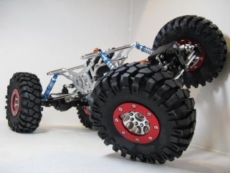
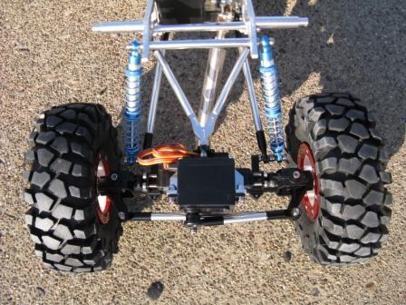
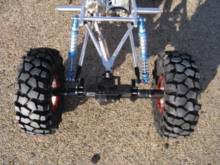
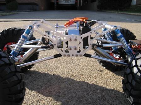
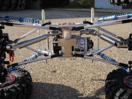
19 After you have your tires mounted, you can remove the nuts and washers from the axles and install the wheels to your Diablo. It should look something like this. You will need to install your body and the rest of your electronics. Please understand that the steering servo will require some adjustment to work properly. When you install your Radio and ESC you will need to refer to there operating manuals for proper setup. Enjoy your new kit and please post up photos of your finished build on our forum here. Please also use the forum if you have questions about your build. Thanks Team RC4WD Below are some additional photos of this Diablo built.
20
21
RC4WD (R2D) R2 Disconnect Transmission Sideway Servo Mount Installation
 R2 Disconnect Transmission Sideway Servo Mount Installation") RC4WD (R2D) R2 Disconnect Transmission Sideway Servo Mount Installation In this manual you will find out how to install the R2D Sideway servo mount. The disconnect tranny is used to help in competition
RC4WD (R2D) R2 Disconnect Transmission Sideway Servo Mount Installation In this manual you will find out how to install the R2D Sideway servo mount. The disconnect tranny is used to help in competition
RC4WD R2 Disconnect Transmission parts replacement guide
 RC4WD R2 Disconnect Transmission parts replacement guide Version 1.1 Thank you for your purchase. Welcome to the RC4WD family. This transmission is a combination of many specially engineered and manufactured
RACER TECH COMMANDER HD TIE ROD INSTALLATION
 RACER TECH COMMANDER HD TIE ROD INSTALLATION NOTE: These instructions are a universal explanation of how to install our HD Tie Rods. All kits are identical for all inner joints and nearly identical for
"The Stick" Assembly Instructions
 Back to Main Page "The Stick" Assembly Instructions In Japanese (pdf): right click and save target as. Introduction: Hello and thank you for buying a Stick chassis from TCS. We appreciate your business
TROLLA LEAVY 97 CM Lawn sweeper
 TROLLA LEAVY 97 CM Lawn sweeper Artikel nr.: 1008 EN Operating manual 014/1 Dear Customer, Congratulations on your new Trolla product. We hope you will enjoy it. Checkout with your new Trolla product may
Replacing the Reciprocator on an SWF Multi-head.
 Replacing the Reciprocator on an SWF Multi-head. Follow the instructions below to replace the reciprocator in the SWF multi-head machines. The tools required are found in the tool kit that came with the
Hardware and Components:
 Hardware and Components: (A) 5/16 x 2 Hex Bolt (B) 5/16 x 2-1/4 Hex Bolt (C) 5/16 x 2-1/2 Hex Bolt (D) 4X 5/16 x 3/4 Hex Bolt (E) 4X 5/16 x 1-1/4 Hex Bolt (F) 11X 5/16 Flat Washer (G) 12X 5/16 Nylock Nut
Sole Fitness E95 Elliptical Trainer TurnKey Delivery and Setup Training
 Sole Fitness E95 Elliptical Trainer TurnKey Delivery and Setup Training Delivery Requirements Ground delivery Inside delivery to customer-specified location Unpack and assemble machine, and remove packing
AX80041 AXA433 AXA433
 42 AX30499 AX30578 AXA083 AXA083 20 AXA465 AXA465 AX80026B AX80078 AX30410 AX30410 AX80078 AX80078 AXA0414 AXA0414 AXA0414 AX80046E AX80046E AX30785 AX30785 AXA175 AXA175 43 AX80044 AX80031 AX80031 AX30531
USE THE PARTS LIST BELOW TO MAKE SURE YOUR KIT IS COMPLETE BEFORE INSTALLATION. IF ANY PIECES ARE MISSING, PLEASE CONTACT:
 1963-1972 C10 Chevy Truck Custom IFS Installation Instructions Tech line: 1-855-693-1259 www.totalcostinvolved.com Read and understand these instructions before starting any work! USE THE PARTS LIST BELOW
RZR 900 Trail / XC / 900 / 1000 S/4
 RZR 900 Trail / XC / 900 / 1000 S/4 Polaris RZR 900 Trail - Trail Fox Edition - XC - 900 S/4-1000 S 2015+ Part #: 5601513, 5601514 Rev. 031417 491 W. Garfield Ave., Coldwater, MI 49036. Phone: 517-278-7768
HQ Pole Upgrade Kit for HQ Adjustable Table and HQ QuilTable Assembly Instructions 1
 HQ Pole Upgrade Kit for HQ Adjustable Table and HQ QuilTable Assembly Instructions QF09775 The pole upgrade kit can be used with or without the QF09700 HQ Precison-Glide track upgrade kit. What s Included
MAG-CONV Basic, 48, 48R & Midline Front Mount
 Parts Required: Tools Used: Mag Wheels Brakes Brake Rods Mounting Bracket Anti Tippers 7/16" Wrench Screw Driver Rubber Mallet 5/8 Wrench 5mm Allen Wrench Step Execution Figures 1 Remove front 5" total
INSTALLATION INSTRUCTIONS CHEVY C-10 INDEPENDENT FRONT SUSPENSION
 INSTALLATION INSTRUCTIONS 73-87 CHEVY C-10 INDEPENDENT FRONT SUSPENSION Please read these instructions completely before starting your installation. Assemble suspension on vehicle before powder-coating
This manual will aid in the assembly of the FireBall V90 and FireBall X90. The assembly of both machines will be identical, unless specified.
 This manual will aid in the assembly of the FireBall V90 and FireBall X90. The assembly of both machines will be identical, unless specified. Step #1 Lay all parts out to verify quantities. (2) 2 x 25-1/4
x4 AX31148 AX30435 Outdrive Shaft AX30435 Outdrive Shaft AX30146 Shock Shaft 3x50mm x4 AX30162 Pin 1.5x8mm AX30163 Pin 2x10mm
 AX30146 Shock Shaft 3x50mm AX30435 Outdrive Shaft AX30435 Outdrive Shaft AX30162 Pin 1.5mm AX30163 Pin 20mm AX31028 Pin 21mm x6 AX30408 Input Shaft 59mm Universal joint Axle Pin holder Joint 10X15MM Joint
Lynx 300X Ultra Main Frame Assembly Manual v1.1
 Lynx 300X Ultra Main Frame Assembly Manual v1.1 Please read this manual fully before commencing assembly. Congratulations on your purchase of the Lynx 300X Ultra Main Frame! This main frame adds a whole
INSTALLATION INSTRUCTIONS
 AUTOMOTIVE PRODUCTS, INSTALLATION INSTRUCTIONS PLATINUM 4 OVAL STEP BAR (90 BENT END) APPLICATION: 2010-2015 Dodge Ram 2500/3500 Mega Cab PART NUMBER: 21-3570, 21-3575, 23-3570, 23-3575, 25-3570, 25-3575,
OPERATOR'S MANUAL 46" SNOW BLADE. Model Numbers OEM IMPORTANT: READ SAFETY RULES AND INSTRUCTIONS CAREFULLY
 OPERATOR'S MANUAL 46" SNOW BLADE Model Numbers 190-833-OEM IMPORTANT: READ SAFETY RULES AND INSTRUCTIONS CAREFULLY MTD PRODUCTS INC. P.O. BOX 368022 CLEVELAND, OHIO 44136-9722 PRINTED IN U.S.A. FORM NO.
DUAL ADJUSTABLE PULLEY IP-D9302 INSTALLATION INSTRUCTIONS
 DUAL ADJUSTABLE PULLEY IP-D9302 INSTALLATION INSTRUCTIONS Copyright 2010. Star Trac by Core Industries, Inc. All rights reserved, including those to reproduce this book or parts thereof in any form without
KWM Gutterman Inc. 5 /6 IRONMAN COMBO CONVERSION
 5 /6 IRONMAN COMBO CONVERSION SECTION: 2 6 To 5 Conversion This section will direct you in converting your combo machine from a 6 to 5 machine. BEFORE BEGINNING CHANGEOVER Eliminate electrical power source
LANDING GEAR. 1. Fit landing gear into slots on bottom of fuselage.
 LANDING GEAR 1. Fit landing gear into slots on bottom of fuselage. 4. Use channel-lock pliers to press blind nuts into position (note: drilled hole should be slightly smaller than shaft of blind nut for
This instruction manual is an in-depth look and explanation of how to assemble and install the Murphy Bed properly and efficiently.
 This instruction manual is an in-depth look and explanation of how to assemble and install the Murphy Bed properly and efficiently. Don t be put off by the size of the instruction manual as the large diagrams
Arc Trainer Main Frame Assembly
 Arc Trainer Main Frame Assembly Kit No. 610AK019-4 Kit No. 630AK019-4 NOTE: This instruction sheet describes how to replace the main frame assembly in the Arc Trainer 610A. Tools Required 3/16 Allen wrench
Hatch Whiteboard: Portable Stand Installation Instructions
 Hatch Whiteboard: Portable Stand Installation Instructions Remove Projector Wall Plate 1. Open the wall mount for the projector. 2. Remove the shipping screw from the front center of the mount arm. 1 P
Patton Robotics ESRA II Expressive System for Robotic Animation
 Patton Robotics ESRA II Expressive System for Robotic Animation Assembly and Operation Instructions Version 1.0 Patton Robotics, LLC. 61 Hagan Drive New Hope, PA 18938 Copyright 2015 Patton Robotics, LLC.
OpenROV. Guide 3 - Electronics. We will now move to the assembly of the electronics that will control the ROV. Written By: OpenROV
 OpenROV Guide 3 - Electronics We will now move to the assembly of the electronics that will control the ROV. Written By: OpenROV 2017 openrov.dozuki.com Page 1 of 33 INTRODUCTION We will introduce soldering
XHD Bull Bar w/ Dual Row LED Light Bar (10-17 Jeep JK)
") XHD Bull Bar w/ Dual Row LED Light Bar (10-17 Jeep JK) PARTS LIST: 1 Driver/Left Side Bull Bar Upright 8 10-1.5mm Hex Nuts 1 Side Bull Bar Upright 4 10-1.5mm Nylon Lock Nuts 1 Top Cross Bar 2 Light Bar
XHD Bull Bar w/ Dual Row LED Light Bar (10-17 Jeep JK) PARTS LIST: 1 Driver/Left Side Bull Bar Upright 8 10-1.5mm Hex Nuts 1 Side Bull Bar Upright 4 10-1.5mm Nylon Lock Nuts 1 Top Cross Bar 2 Light Bar
RPS. XR Front Drive Updates CORPORATION
 FACTORY CAT 1. To start a replacement of the XR Front Wheel Drive, make sure the machine is on level ground with the rear wheels chocked and always disconnect the batteries. 2. Locate the Positive and
INSTALLATION INSTRUCTIONS FOR FRONT CASTING DECK RAIL Ranger
 INSTALLATION INSTRUCTIONS FOR FRONT CASTING DECK RAIL Ranger TOOLS REQUIRED FOR INSTALLATION: Drill motor, (1) 5/16 inch drill bit, (1) 13/64 drill bit, (1) 3/16 inch hex wrench (1) 3/32 inch hex wrench.
For additional assistance call
 The following pages will help guide you through the process of assembling your new 48 custom prize wheel. Choose an assembly area with plenty of room to lay your pieces on the floor and also a bench or
ORTOP Modular Robot v3.0 Arm Assembly
 Base Plate Assembly Parts Needed: Arm Assembly BAG 1 2 Socket Head Cap Screw, 1-1/4" 2 Socket Head Cap Screw, 1/2" 2 Button Head Cap Screw, 3/8" 6 Nuts 1 Gear Hub Spacer 1 Flat Building Plate 1 Single
Hardware and Components:
 Hardware and Components: (A) 4X 5/16 x 1 Carriage Bolt (B) 2X 5/16 x 2-1/4 Carriage Bolt (C) 2X 5/16 x 3-1/4 Hex Bolt (D) 2X 5/16 x 3/4 Hex Bolt (E) 2X 5/16 x 1-1/4 Hex Bolt (F) 5/16 x 2-1/4 Hex Bolt (G)
Assembly & Installation Instructions FOR VEHICLE MOUNT KIT USING VEHICLE CENTER MEMBER
 Assembly & Installation Instructions FOR VEHICLE MOUNT KIT 991002 USING VEHICLE CENTER MEMBER 9910092 TO FIT 99 - LATER Chevrolet 2500 Silverado 4x4 and 3500 Pickup 4x4 99 - LATER GM 2500 Sierra 4x4 and
08+ KAWASAKI KLR PD NERF
 08+ KAWASAKI KLR PD NERF 0505-1299 Before you begin, place the bike on a hard level surface where you have room to work. Lay out the parts included in this kit and compare to the parts list on page 5 of
FLOE DOCK FURNITURE WARNING ASSEMBLY INSTRUCTIONS
 FLOE DOCK FURNITURE ASSEMBLY INSTRUCTIONS KIT P/N 510-00400-02 KIT P/N 510-00405-02 KIT P/N 510-00406-02 KIT P/N 510-00410-02 WARNING IT IS THE INSTALLER S RESPONSIBILITY TO PROPERLY INSTALL this chair
CONTROLS KIT FOR ALL # & # HARLEY DAVIDSON SPORTSTER MODELS
 INSTALLATION INSTRUCTIONS TC BROS. CHOPPERS PART #0-0075 & #0-0076 (No Pegs) FORWARD CONTROLS KIT FOR ALL 00-0 HARLEY DAVIDSON SPORTSTER MODELS If downloading & printing these instructions online, be sure
OPERATIONS MANUAL. Port-O-Slitter
 Tapco Products Company The World Leader in Specialty Tools for the Professional Port-O-Slitter OPERATIONS MANUAL General instructions, set up, accessories and guide to using your portable precision slitting,
Hollywood Swing Away 2 and 4 Bike Racks Assembly and Installation Guide
 Hollywood Swing Away 2 and 4 Bike Racks Assembly and Installation Guide Tools Required: two adjustable wrenches, pliers, ¾ socket wrench recommended Note: please do assembly near your vehicle as you Can
IDR assembly instructions:
 IDR assembly instructions: Required Tools: 2 X 12mm Open End Wrench 14mm open end wrench #2 Phillips Head Screw Driver (Drill with adjustable torque clutch recommended) 8mm nut driver (Supplied in IDR-AK)
E4-WM5-Y525A00 MOUNTING INSTRUCTION
 RAM 2500/3500 4WD B8 5100 (Dual Steering Damper Kit) The installation of these steering dampers must be performed only by experienced and qualified personnel. Read and follow the installation instructions
Hiniker Company th St. P.O. Box 3407 Mankato, MN VEHICLE INSTALLATION INSTRUCTIONS FOR: CHEV/GMC 4x4: K1500 SILVERADO/SIERRA
 VEHICLE INSTALLATION INSTRUCTIONS FOR: CHEV/GMC x: 007 03 K500 SILVERADO/SIERRA Page of 5 Hiniker Company 58766 0th St. P.O. Box 307 Mankato, MN 5600 INSTRUCTION SHEET NO: 505 Rev. A August 0, 03 IMPORTANT:
The Portable Open Source 3D Printer
 http://web.archive.org/web/201502142011/http://www.tantillus.org/build_3.html Page 1 of 12 captures 12 Oct 12 - Feb 15 The Portable Open Source 3D Printer Home Start Case X/Y Axis Extruder Z Axis Electronics
Bushwacker Jeep Flat Style Fender Flares Rear Pair (JK Wrangler 2dr)
") Bushwacker Jeep Flat Style Fender Flares Rear Pair (JK Wrangler 2dr) Note: These instructions involve cutting parts of your vehicle. Please read all instructions prior to starting. Installation Time: 3-4
Bushwacker Jeep Flat Style Fender Flares Rear Pair (JK Wrangler 2dr) Note: These instructions involve cutting parts of your vehicle. Please read all instructions prior to starting. Installation Time: 3-4
EZ-HAUL GARDEN CRATE WAGON
 099 EZ-HAUL GARDEN CRATE WAGON 855 00 FarmTek All Rights Reserved. Reproduction is prohibited without permission. STK# Description 099 Garden Wagon Revision date: 09.0.0 CARE AND MAINTENANCE READ THIS
RYOBI. 10 in. (254 mm) TABLE SAW MODEL NO. BTS15 REPAIR SHEET
 TABLE SAW MODEL NO. BTS15 REPAIR SHEET") RYOBI 0 in. ( mm) TABLE SAW MODEL NO. BTS REPAIR SHEET FIGURE A 0 0 0 0 The model number will be found on a plate attached to the motor housing. Always mention the model number in all correspondence regarding
RYOBI 0 in. ( mm) TABLE SAW MODEL NO. BTS REPAIR SHEET FIGURE A 0 0 0 0 The model number will be found on a plate attached to the motor housing. Always mention the model number in all correspondence regarding
INSTALLATION INSTRUCTIONS GRILLE GUARD 09-ON DODGE RAM PART #
 INSTALLATION INSTRUCTIONS GRILLE GUARD 09-ON DODGE RAM PART # PARTS LIST: Qty Description Qty Description 1 Grille Guard 8 12-1.75mm x 35mm Hex Bolts 2 Brackets (for trucks without 22 12mm x 30.1mm OD
FORZA 700 SPEED Supplemental manual
 The FORZA 700 has evolved into a Speed Monster. The finely honed form minimizes air resistance, and the forward tilting rotor head helps transform all available power into speed. Fly beyond limits with
Medium HoneyBadger Chase Rack Installation Instructions
 PREPARATION Medium HoneyBadger Chase Rack Installation Instructions 1. Disconnect the negative terminal on the battery. Park the vehicle on level ground and set the emergency brake. 2. We recommend reading
INSTALLATION INSTRUCTIONS / DODGE RAM CREW CAB 2500/3500
 INSTALLATION INSTRUCTIONS 225019 / 225019-2 2010 DODGE RAM CREW CAB 2500/3500 PARTS LIST: Qty Description Qty Description 1 Driver/Left Side Bar 4 Plastic Square Retainer 1 Side Bar 2 12mm x 120mm Hex
INSTALLATION INSTRUCTIONS DODGE RAM 2 & 4WD 1500 PART # P5058
 INSTALLATION INSTRUCTIONS 2009-13 DODGE RAM 2 & 4WD 1500 PART # P5058 PARTS LIST: Qty Description Qty Description 1 Grille Guard 12 12-1.75mm Hex Nuts 2 Upper Frame Mounting s (for trucks without tow hooks
INSTALLATION INSTRUCTIONS GRILLE GUARD RAM 1500 PART # 5058/5058-2
 INSTALLATION INSTRUCTIONS GRILLE GUARD PART # 5058/5058-2 PARTS LIST: Qty Description Qty Description 1 Grille Guard 8 12-1.75mm x 35mm Hex Bolts 2 Upper Frame Mounting s (for trucks without tow hooks
Bushwacker Jeep Flat Style Fender Flares Front Pair
 Bushwacker Jeep Flat Style Fender Flares Front Pair Note: These instructions involve cutting parts of your vehicle. Please read all instructions prior to starting. Installation Time: 3-4 Hours Tools Required:
Big Block Installation Manual For Systems without A/C
 Big Block Installation Manual For Systems without A/C Billet Specialties, Inc. 500 Shawmut Ave. La Grange, IL 60526 Tech Line (708) 588-0505 Fax (708) 588-7181 Hardware List For Chevrolet Big Block Tru
TIRE RACK INSTALLATION INSTRUCTIONS Dodge Sprinter
 Aluminess Products Inc 9402 Wheatlands Ct. #A Santee, CA 92071 619-449-9930 TIRE RACK INSTALLATION INSTRUCTIONS 07-11 Dodge Sprinter Please read before beginning Stainless steel hardware may bind together
Otter Pro XT Cottage Installation and Set-Up Instructions
 Otter Pro XT Cottage Installation and Set-Up Instructions Otter Pro XT Cottage Fits Small Ultra-Wide Otter Pro and Otter II Sled Only Parts Identification and Check List MODEL NUMBERS: Complete Pkg Pro
RBP-1215B-RX DODGE RAM QUAD CAB RX3
 RBP-1215B-RX3 2002-2017 DODGE RAM 15-3500 QUAD CAB RX3 Passenger side RX-3 Side Step Drill Template Passenger side rear Modular Bracket (6) L Support Brackets Driver side rear Modular Bracket Driver side
Installation instructions for FC14S Forward Controls for Shadow ACE and Aero 1100
 Installation instructions for FC14S Forward Controls for Shadow ACE and Aero 1100 It is highly recommended that you use a thread lock compound such as Loctite brand on all threads to keep them from vibrating
400GTO Lubrication Guide
 400GTO Lubrication Guide Lubrication Guidelines for the following equatorial mounting: 400GTO Servo with GTOCP2 or CP3 Controller For other 400 models please review other postings as they become available.
JK Rear Inner Fenders
 INSTALLATION INSTRUCTIONS INST-17-05-080_A JK Rear Inner Fenders IMPORTANT: Thank you for purchasing this Poison Spyder product. Please read through this entire document before proceeding with installation.
REPAIR INSTRUCTIONS. Cat. No Cat. No MILWAUKEE ELECTRIC TOOL CORPORATION. SDS Max Demolition Hammer. SDS Max Rotary Hammer
 Cat. No. 9-0 SDS Max Demolition Hammer Cat. No. -0 SDS Max Rotary Hammer MILWAUKEE ELECTRIC TOOL CORPORATION W. LISBON ROAD BROOKFIELD, WISCONSIN 00-0 8-9-0 d 000 8-9-0 d Special Tools Require Forcing
Installation Guide. Mounting Kit for Mounting Philips Avalon CTS Cordless Fetal Transducer System on Wall, 2'' Post, Rail, or Slide-on Mounting Plate
 Installation Guide Mounting Kit for Mounting Philips Avalon CTS Cordless Fetal Transducer System on Wall, 2'' Post, Rail, or Slide-on Mounting Plate The purpose of this guide is to: 1. Describe mounting
Code Product Qty 1 Top Vertex 3 2 Hot End Housing 1 3 Bottom Vertex 3 4 Print Platform Lock 3 5 End Stop Holder 3 6 Filament Feeder Motor Bracket 1 7
 List of Parts Code Product Qty 1 680mm Extrusion 3 2 Power Supply 1 3 240mm Extrusion 9 4 42mm Nema 17 Stepper Motor 3 5 Slider-Hotend Connecting Rod 6 6 48mm Nema 17 Stepper Motor 1 7 Linear Rail with
Side Mount INSTRUCTION BOOKLET #C122 BED STYLE: PARK CITY
 Side Mount BED STYLE: PARK CITY INSTRUCTION BOOKLET #C1 WARNING! ALL MURPHY/WALLBED SYSTEMS CONTAIN STORED ENERGY. FAILURE TO USE AND FOLLOW THESE INSTRUCTIONS DURING THE INSTALLATION PROCESS COULD RESULT
Installation Guide for Rough Country 1.25 inch Body Lift Kit w/o Shocks (07-15 Wrangler JK 4 Door) Item # J10048 Option B; Manual
 Item # J10048 Option B; Manual") Installation Guide for Rough Country 1.25 inch Body Lift Kit w/o Shocks (07-15 Wrangler JK 4 Door) Item # J10048 Option B; Manual Installation Time: 3 Hours Tools Required: Jack (Tall enough to reach body
Installation Guide for Rough Country 1.25 inch Body Lift Kit w/o Shocks (07-15 Wrangler JK 4 Door) Item # J10048 Option B; Manual Installation Time: 3 Hours Tools Required: Jack (Tall enough to reach body
4600 Series Rim Narrow Stile Exit Device Installation Instructions I-ED01162
 DEVICES COVERED IN THIS DOCUMENT: 4600 Series Rim Panic Narrow Stile Exit Device 4600 Series Rim Fire Narrow Stile Exit Device OVERVIEW Outside of Door RHR LHR Inside of Door APPLICATIONS 4950 BLADE STOP
ASSEMBLY & INSTALLATION INSTRUCTIONS
 ASSEMBLY & INSTALLATION INSTRUCTIONS VEHICLE MOUNT KIT 118 AND VEHICLE CENTER MEMBER 6050 TO FIT 2008 & LATER FORD F250-F550 4X4 Sno-Way, Down Pressure and EIS are registered trademarks of Sno-Way International,
Thor Audi A4/S4 Skid Plate Installation Instructions
 Thor Audi A4/S4 Skid Plate Installation Instructions Parts List: 1 Aluminum Skid Plate 2 Aluminum Side Wings 10 10mm Flat Washers 3 8mm Flat Washers 3 8mm Speed Clips 2 10x40mm Bolts 3 8x35mm Bolts 2 Rivet-nuts
EmagiKit. Privacy Pod Plus. Quiet. Easy. Affordable. INSTRUCTIONS ASSEMBLY
 EmagiKit Privacy Pod Plus Quiet. Easy. Affordable. INSTRUCTIONS ASSEMBLY DIMENSIONS AND COMPONENTS 47 47 Ceiling Unit 2-B 2-L 2-R Glass Door Corner Trim Door Handle 90 Adjustable Height Work Surface 1-B
Star Trac Turbo Trainer Assembly & Setup
 Star Trac Turbo Trainer Use the following procedures to unpack and assemble your Turbo Trainer manufactured by Star Trac. UNPACKING AND PARTS LIST Position the shipping carton so the Heavy End logo is
Midwest RDH Handpiece Repair Procedure
 Midwest RDH Handpiece Repair Procedure The Midwest RDH handpiece is fairly common and is used by hygienists to clean teeth. The most common problems for this handpiece include a bad prophy head or a dirty
A500 ASSEMBLY & INSTALLATION INSTRUCTIONS
 ASSEMBLY & INSTALLATION INSTRUCTIONS 1 CONTENTS 2 Component Parts A B Canopy Mounting Plate C Cap (3) D Threaded Nipple E Threaded Standoffs (2) F Anchors (8) G #10 Screws (8) H Safety Cable (2) I Safety
INSTALLATION INSTRUCTIONS GRILLE GUARD CHEVY TAHOE / AVALANCHE 1500/ SUBURBAN 1500 PART # /502795
 (W) INSTALLATION INSTRUCTIONS GRILLE GUARD PART # 502794/502795 PARTS LIST: 1 Grille Guard 2 12-1.75mm x 140mm Hex Bolts 2 Frame Mounting Brackets 8 12-1.75mm x 30mm Hex Bolts 2 Lower Support Brackets
2017 Current Ford Raptor ADD Pro Front Bumper Installation Instructions
 2017 Current Ford Raptor ADD Pro Front Bumper Installation Instructions PREPARATION 1. Disconnect the negative terminal on the battery. Park the vehicle on level ground and set the emergency brake. 2.
INSTALLATION INSTRUCTIONS 3 ROUND & 4 OVAL SIDEBAR (90-DEG BENT END) DODGE RAM MEGA CAB PART NUMBER SB1214S SB1214B
 DODGE RAM MEGA CAB PART NUMBER SB1214S SB1214B") INSTALLATION INSTRUCTIONS PART NUMBER SB1214S SB1214B PARTS LIST: Qty Description Qty Description 1 Driver/Left Sidebar 4 12mm x 32mm OD x 3mm Flat Washers 1 Passenger/Right Sidebar 4 12mm Lock Washers
INSTALLATION INSTRUCTIONS PART NUMBER SB1214S SB1214B PARTS LIST: Qty Description Qty Description 1 Driver/Left Sidebar 4 12mm x 32mm OD x 3mm Flat Washers 1 Passenger/Right Sidebar 4 12mm Lock Washers
FM2113PC/FM2114PC SBC Top Mount Alt, w/ A/C & Power Steering
 10) At this time assemble the power steering bracket and pump assembly from the instructions provided with the power steering bracket beginning at step 7. Return to step 10 on this sheet when complete.
Square Wheel Belt Grinder Models: 4103, 4106, and 4126AC
 This Manual is Bookmarked Operating Instructions Parts Manual Square Wheel Belt Grinder Models: 4103, 4106, and 4126AC WHM TOOL GROUP 2420 Vantage Drive Elgin, Illinois 60123 Ph.: 800-274-6848 www.wmhtoolgroup.com
Required Tools: Procedure:
 Depending on the materials you process through your chipper, their moisture content, the climate you live in, and many other factors you may have difficulty removing the rotor from the engine shaft. The
Rudder Pedal Kit. Assembly Manual. V1.0 July 2010.
 Rudder Pedal Kit Assembly Manual V1.0 July 2010. Introduction: Thank you for your purchase of our Boeing 737 Rudder Pedal Kit. many years of faithful service from our product. We hope you will have Our
DYNATRAC BALL JOINT REBUILD INSTRUCTIONS V4.0
 DYNATRAC PRODUCTS 2007-2016 4X4 JEEP JK HEAVY DUTY BALL JOINT JP44-2X3050-C DYNATRAC BALL JOINT REBUILD INSTRUCTIONS V4.0 WARNING: Improper use or installation of this product can cause major failures
LB. POLY PRO DROP SPREADER
 owners manual Model No. -02882 17 LB. POLY PRO DROP SPREADER CAUTION: Read Rules for Safe Operation and Instructions Carefully Safety Assembly Operation Maintenance Parts the fastest way to purchase parts
It is highly recommended that you use a thread lock compound such as Loctite brand on all threads to keep them from vibrating loose.
 Installation instructions for FC12 Forward Controls for Kawasaki Vulcan 750 It is highly recommended that you use a thread lock compound such as Loctite brand on all threads to keep them from vibrating
Ford Pick Up Rear leaf Spring Kit Installation Instructions
 1948-1956 Ford Pick Up Rear leaf Spring Kit Installation Instructions 1-800-984-6259 www.totalcostinvolved.com Parts 48 inch leaf (2) springs (4) U-bolts 3/8-24 x l 1/4bolts (16) & nuts (2) 1/2-20 x 4
FM2113PC/FM2114PC SBC Top Mount Alt, w/ A/C & Power Steering
 10) At this time assemble the power steering bracket and pump assembly from the instructions provided with the power steering bracket beginning at step 7. Return to step 10 on this sheet when complete.
RC-TEK Ltd. SKYSHARK 450 REFERENCE MANUAL. Copyright 2007 RC-TEK, All Rights Reserved
 RC-TEK Ltd. SKYSHARK 450 REFERENCE MANUAL Frame Assembly On each page of this manual the parts required for each step will be listed below along with a set of images showing the stages of each part of
* Drill and 3/32" drill bit: for drilling holes in the factory plastic upper for the screws to secure the brackets (factory upper installation only)
") * Two slider windows (four sliders windows for the 4-door kit) * Four brackets to secure the windows to the upper door frames (8 brackets for the 4-door kit) * Weatherstrip to seal the windows to the half
* Two slider windows (four sliders windows for the 4-door kit) * Four brackets to secure the windows to the upper door frames (8 brackets for the 4-door kit) * Weatherstrip to seal the windows to the half
Installation Instructions
 TOYOTA 16K Industry Standard Rail Custom Mounting Kit #2748 Gross Trailer Weight (Maximum)...16,000 lbs. Vertical Load Weight (Max. Pin Weight)...4,000 lbs. SYSTEM TOW CAPACITY Please note, in order to
Rugged Ridge Engine Transmission Skid Plate JK
 Installation Time: 1-2 Hours Tools Required: Rugged Ridge Engine Transmission Skid Plate 2012-2017 JK Sockets: 16mm, 17mm, 18mm deep well Socket Wrench Wrenches: 16mm, 18mm Torque Wrench Drill ½ Drill
For installation assistance, contact SARGENT at DOORS SHOWN HERE SWING IN FOR ILLUSTRATION PURPOSES ONLY.
 SARGENT Installation Instructions for LP8600 x LR8600 & 12-LP8600 x 12-LR8600 Series Low Profile Panic and Fire Exit Devices on Double Egress & Double Doors or LS8600 & 12-LS8600 Low Profile Exit Device
Your new. Rose. spinning wheel. majacraft. all you need to spin your dreams... majacraft
 Your new Rose spinning wheel all you need to spin your dreams... 1 Welcome to the Majacraft family Congratulations on purchasing a new Majacraft Rose. We are very proud of this wheel and hope that it allows
PROSTEER BALL JOINT REBUILD INSTRUCTIONS V1.0
 DYNATRAC PRODUCTS 2003-2010 4X4 DODGE 2500/3500 HEAVY DUTY BALL JOINT PROSTEER BALL JOINT REBUILD INSTRUCTIONS V1.0 WARNING: Improper use or installation of this product can cause major failures that could
Installation Instructions
 DODGE 16K Industry Standard Rail Custom Mounting Kit #2728 Gross Trailer Weight (Maximum)...16,000 lbs. Vertical Load Weight (Max. Pin Weight)...4,000 lbs. SYSTEM TOW CAPACITY Please note, in order to
w w w. h d o n l i n e s h o p. d e TIMKEN BEARING CONVERSION TOOL GENERAL INSTALLATION -J04672 REV Kit Number Models
 -J067 REV. 008-07- GENERAL Kit Number 8-08 Models TIMKEN BEARING CONVERSION TOOL For model fitment information, see the P&A Retail Catalog or the Parts and Accessories section of www.harley-davidson.com
Installation Instructions
 CHEVY / GMC 20K Industry Standard Rail Custom Mounting Kit #2724 Gross Trailer Weight (Maximum)...20,000 lbs. Vertical Load Weight (Max. Pin Weight)...5,000 lbs. SYSTEM TOW CAPACITY Please note, in order
SERVICE PARTS LIST PAGE 1 OF 6 BASE ASSEMBLY SPECIFY CATALOG NO. AND SERIAL NO. WHEN ORDERING PARTS 12" DUAL BEVEL COMPOUND MITER SAW B27B
 PAGE 1 OF 6 BASE ASSEMBLY 00 0 EXAMPLE: Component Parts (Small #) Are Included When Ordering The Assembly (Large #). SPECIFY CATALOG NO. AND NO. WHEN ORDERING PARTS = Part number change from previous service
Installation instructions for FC17 Forward Controls for Triumph Rocket III Roadster
 Installation instructions for FC17 Forward Controls for Triumph Rocket III Roadster It is highly recommended that you use a thread lock compound such as Loctite brand on all threads to keep them from vibrating
WILDING WALLBEDS INSTALLATION INSTRUCTION Side Mount
 WILDING WALLBEDS INSTALLATION INSTRUCTION Side Mount For Wallbed models: Do-It-Yourself Insturction booklet C92 WARNING! ALL MURPHY/WALLBED SYSTEMS CONTAIN STORED ENERGY. FAILURE TO USE AND FOLLOW THESE
Owner s Manual LSP38 38 Lawn Sweeper
 Owner s Manual LSP38 38 Lawn Sweeper Manual Contents Safety Instructions Assembly Operation Maintenance Parts Warranty 2 4-13 2 11 14-15 16 Your Lawn Sweeper Congratulations on your purchase of a new Precision
Fig A ADDICTIVE DESERT DESIGNS. Preparation: Removal:
 Preparation: Disconnect the negative battery terminal. Park the vehicle on level ground and set the emergency brake. We recommend reading through the installation instructions in whole before performing
TRIUMPH TIGER 800 PD NERF
 TRIUMPH TIGER 800 PD NERF 0505-0 Step Before you begin, place the bike on a hard level surface where you have room to work. Lay out the parts included in this kit and compare to the parts list on page