IC Logic Families and Characteristics. Dr. Mohammad Najim Abdullah
|
|
|
- Griselda Copeland
- 5 years ago
- Views:
Transcription

1 IC Logic Families and Characteristics Introduction miniature, low-cost electronics circuits whose components are fabricated on a single, continuous piece of semiconductor material to perform a high-level function. usually referred to as a monolithic IC. first introduced in 1958 categorized as digital or linear ICs or according to the level of complexity of the IC Packaging 1. protect the chip from mechanical damage and chemical contamination. 2. provides a completed unit large enough to handle. 3. so that it is large enough for electrical connections to be made. 4. material is molded plastic, epoxy, resin, or silicone. Ceramic used if higher thermal dissipation capabilities required. Metal/glass used in special cases. Three most common packages for ICs are dual-in-line (DIPS) (most common) flat pack axial lead (TO5) Digital IC terminology Although there are many manufacturers of digital ICs and several logic families, a fair amount of terminology associated with digital ICs is somewhat standardized between the various manufacturers and logic families. Common digital IC terminology Voltage and Current Levels
2 Symbol VIH VIL VOH VOL IIH IIL IOH IOL Definition HIGH-state input voltage, corresponding to logic 1 at input LOW-state input voltage, corresponding to logic 0 at input HIGH-state output voltage, corresponding to logic 1 at output LOW-state output voltage, corresponding to logic 0 at output HIGH-state input current; current flowing from input when the input voltage corresponds to logic 1. LOW-state input current; current flowing from an input when the input voltage corresponds to logic 0. HIGH-state output current; current flowing from output when the output voltage corresponds to logic 1. LOW-state output current; current flowing from an output when the output voltage corresponds to logic 0. Properties of Digital ICs Fan-in Fan-in (input load factor) is the number of input signals that can be connected to a gate without causing it to operate outside its intended operating range. expressed in terms of standard inputs or units loads (ULs) Example: for standard TTL one unit load is defined as 1 UL = 40µA in the HIGH state 1.6mA in the LOW state to determine the fan-in (or fan-out) for a gate, take the lower of A fan-in of 8 means that 8 unit loads can be safely connected to the gate inputs. Fan-out Fan-out (output load factor) is the maximum number of inputs that can be driven by a logic gate. A fan out of 10 means that 10 unit loads can be driven by the gate while still maintaining the output voltage within specifications for logic levels 0 and 1. Example: A unit load for some particular logic family is as follows:
3 Determine the fan-in and fan-out for a gate in this family that has the following parameters: IOH = 400µA IOL = 10mA IIH = 150µA IIL = 4 ma Solution: fan-in = 150/50 = 3 UL or 4/1 = 4 UL therefore fan-in = 3. fan-out = 400/50 = 8 UL or 10/1 = 10 UL therefore fan-out = 8 UL. Propagation Delays. - the delay before a change in the input is reflected in the output. tphl : delay time in going from logic 1 to logic 0 (turn-off delay). tplh : delay time in going from logic 0 to logic 1(turn-on delay). Noise Margin/Immunity - ability of the gate to tolerate fluctuations of the voltage levels. VNH = HIGH-state noise margin VNL = LOW-state noise margin VIL = LOW-state input voltage VIH = HIGH-state input voltage VOL = LOW-state output voltage VOH = HIGh-state output voltage where
4 VNH = VOH VIH VNL = VIL VOL Manufacturers specify voltage limits to represent the logical 0 or 1. These limits are not the same at the input and output sides. For example, a particular gate A may output a voltage of 4.8V when it is supposed to output a HIGH but, at its input side, it can take a voltage of 3V as HIGH. In this way, if any noise should corrupt the signal, there is some margin for error. Consider the following case where the output of logic circuit A is connected to the input of logic circuit B. When the output of A is low, VO, the input to B, Vi, should also be low. But because of noise Vi is not exactly VO but could higher. As long as Vi is not more than VIL, B will still take the signal as a LOW. If Vi is more than VIL though, then the signal may not appear as a LOW. The effect of noise is shown in the following figure.
5 Power Dissipation Power dissipation is the amount of heat (in mill watts) that the IC dissipates in the form of heat. IC Logic Families Thus far, we have specified the logic level as either 0 or 1, or HIGH or LOW. In circuit implementation, we will have to specify the actual voltage/current levels that constitute a HIGH or a LOW. These standardized voltage/current levels are grouped in families of digital ICs so that ICs belonging to the same family will have the same characteristics. Common families are TTL: transistor-transistor logic ECL: emitter-coupled logic. IIL integrated injection logic. MOS ICs: metal-oxide-semiconductor ICs. TTL - most popular and widely used IC logic family. - introduced by Texas Instruments in operate from a +5V supply. - Standardized labeling system starting with 54 or 74. For example 7400, 7401, A HIGH is nominally +5V while a LOW is nominally 0V or GROUND. - to provide greater flexibility with regard to speed and power dissipation considerations, the following sub-families have been developed: 7400 standard series. 74L00 low-power series 74H00 high-speed series 74S00 Schottky series 74LS00 low-power Schottky series.
6 Totem Pole TTL The basic TTL NAND gate circuit is shown below: Transistors Q3 and Q4 form what is known as a totem pole arrangement.
7 The features of this arrangement are low power consumption fast switching low output impedance Noise Margins maximum logic 0 output, VOL = 0.4 V maximum logic 0 input, VIL = 0.8 V therefore, the LOW state noise margin is VNL= 0.8V - 0.4V = 400 mv. Similarly, minimum logic 1 output, VOH = 2.4 V minimum logic 1 input, VIH = 2.0 V therefore, the HIGH state noise margin is VNH = = 400 mv. These are the guaranteed worse case. The actual values typically are VNL= 1 V and VNH = 1.6 V. Low-power TTL designated as 74L00. essentially same as standard TTL except that the resistor values are increased. This will decrease power consumption (typical 1 mw) but there is a corresponding decrease in speed (propagation delay of 33 ns). low-power TTL gates have a fan-out of 10 other low-power TTL gates but will only drive two standard series TTL gate. High-speed TTL designated as 74H00 resistor values have been decreased. Speed is increased (delay = 6 ns) but power dissipation will increase (22 mw). Summary of fan-out capabilities for the TTL series
8 Unused Inputs on TTL devices Unused inputs on TTL gates behave as though a logic 1 is connected to them. This present a problem with OR or NOR gates. With AND or NAND gates, the logic would not pose a problem but for better noise immunity, the inputs should not be allowed to "float". It is advisable to connect unused HIGH inputs to +5V through resistors ( pull-up resistors) of 1kΩ. Unused inputs should be connected as follows: TTL open-collector devices In some applications, it is necessary to connect the output of the gates together. In such cases, TTL open-collector devices are used as the output of standard totempole TTL gates cannot be connected together. To connect the output of standard totem-pole TTL gates together, we can use an AND gate as below, but this is impractical if more signals need to be ANDed.
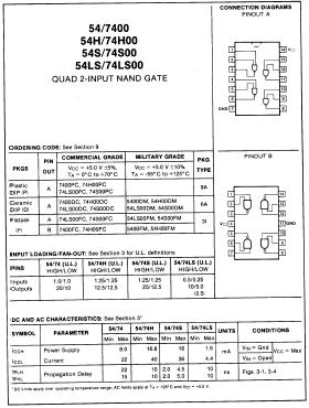
9 To overcome this problem, TTL manufacturers have developed a series of open collector logic devices. As can be seen from the diagram, an external resistor, called a pull-up resistor must be connected from the power supply to the output of the device. Wiring the open-collector NAND gate output directly will accomplish the same result as the circuit earlier. We call such circuit wired AND or wired OR. IC Data Sheets All manufacturers of ICs print data sheets for each type of IC they manufacture. The purpose of the data sheet is to provide the user with information about the IC such as the pin assignments, electrical and mechanical specifications, logic function and ratings. The following is a sample data sheet of the 7400 IC.
10
1 IC Logic Families and Characteristics
 2141 Electronics and Instrumentation IC1 1 IC Logic Families and Characteristics 1.1 Introduction miniature, low-cost electronics circuits whose components are fabricated on a single, continuous piece
SN55451B, SN55452B, SN55453B, SN55454B SN75451B, SN75452B, SN75453B, SN75454B DUAL PERIPHERAL DRIVERS
 PERIPHERAL DRIVERS FOR HIGH-CURRENT SWITCHING AT VERY HIGH SPEEDS Characterized for Use to 00 ma High-Voltage Outputs No Output Latch-Up at 0 V (After Conducting 00 ma) High-Speed Switching Circuit Flexibility
Module-1: Logic Families Characteristics and Types. Table of Content
 1 Module-1: Logic Families Characteristics and Types Table of Content 1.1 Introduction 1.2 Logic families 1.3 Positive and Negative logic 1.4 Types of logic families 1.5 Characteristics of logic families
Logic Families. Describes Process used to implement devices Input and output structure of the device. Four general categories.
 Logic Families Characterizing Digital ICs Digital ICs characterized several ways Circuit Complexity Gives measure of number of transistors or gates Within single package Four general categories SSI - Small
4-bit counter circa bit counter circa 1990
 Digital Logic 4-bit counter circa 1960 8-bit counter circa 1990 Logic gates Operates on logical values (TRUE = 1, FALSE = 0) NOT AND OR XOR 0-1 1-0 0 0 0 1 0 0 0 1 0 1 1 1 0 0 0 1 0 1 0 1 1 1 1 1 0 0 0
Note that none of the above MAY be a VALID ANSWER.
 ECE 270 Learning Outcome 1-1 - Practice Exam / Solution LEARNING OUTCOME #1: an ability to analyze and design CMOS logic gates. Multiple Choice select the single most appropriate response for each question.
Logic Families. A-PDF Split DEMO : Purchase from to remove the watermark. 5.1 Logic Families Significance and Types. 5.1.
 A-PDF Split DEMO : Purchase from www.a-pdf.com to remove the watermark 5 Logic Families Digital integrated circuits are produced using several different circuit configurations and production technologies.
Digital Integrated Circuits - Logic Families (Part II)
") Digital Integrated Circuits - Logic Families (Part II) MOSFET Logic Circuits MOSFETs are unipolar devices. They are simple, small in size, inexpensive to fabricate and consume less power. MOS fabrication
Digital Integrated Circuits - Logic Families (Part II) MOSFET Logic Circuits MOSFETs are unipolar devices. They are simple, small in size, inexpensive to fabricate and consume less power. MOS fabrication
SN54LS06, SN74LS06, SN74LS16 HEX INVERTER BUFFERS/DRIVERS WITH OPEN-COLLECTOR HIGH-VOLTAGE OUTPUTS
 Convert TTL Voltage Levels to MOS Levels High Sink-Current Capability Clamping Diodes Simplify System Design Open-Collector Driver for Indicator Lamps and Relays s Fully Compatible With Most TTL Circuits
4-bit counter circa bit counter circa 1990
 Digital Logic 4-bit counter circa 1960 8-bit counter circa 1990 Logic gates Operates on logical values (TRUE = 1, FALSE = 0) NOT AND OR XOR 0-1 1-0 0 0 0 1 0 0 0 1 0 1 1 1 0 0 0 1 0 1 0 1 1 1 1 1 0 0 0
SN54LS07, SN74LS07, SN74LS17 HEX BUFFERS/DRIVERS WITH OPEN-COLLECTOR HIGH-VOLTAGE OUTPUTS
 Convert TTL Voltage Levels to MOS Levels High Sink-Current Capability Clamping Diodes Simplify System Design Open-Collector Driver for Indicator Lamps and Relays description These hex buffers/drivers feature
SN75374 QUADRUPLE MOSFET DRIVER
 SLRS28 SEPTEMBER 1988 Quadruple Circuits Capable of Driving High-Capacitance Loads at High Speeds Output Supply Voltage Range From 5 V to 24 V Low Standby Power Dissipation V CC3 Supply Maximizes Output
Chapter 15 Integrated Circuits
 Chapter 15 Integrated Circuits SKEE1223 Digital Electronics Mun im/arif/izam FKE, Universiti Teknologi Malaysia December 8, 2015 Overview 1 Basic IC Characteristics Packaging Logic Families Datasheets
SN55115, SN75115 DUAL DIFFERENTIAL RECEIVERS
 SN, SN7 Choice of Open-Collector or Active Pullup (Totem-Pole) Outputs Single -V Supply Differential Line Operation Dual-Channel Operation TTL Compatible ± -V Common-Mode Input Voltage Range Optional-Use
Module-3: Metal Oxide Semiconductor (MOS) & Emitter coupled logic (ECL) families
 & Emitter coupled logic (ECL) families") 1 Module-3: Metal Oxide Semiconductor (MOS) & Emitter coupled logic (ECL) families 1. Introduction 2. Metal Oxide Semiconductor (MOS) logic 2.1. Enhancement and depletion mode 2.2. NMOS and PMOS inverter
1 Module-3: Metal Oxide Semiconductor (MOS) & Emitter coupled logic (ECL) families 1. Introduction 2. Metal Oxide Semiconductor (MOS) logic 2.1. Enhancement and depletion mode 2.2. NMOS and PMOS inverter
IC Logic Families. Wen-Hung Liao, Ph.D. 5/16/2001
 IC Logic Families Wen-Hung Liao, Ph.D. 5/16/2001 Digital IC Terminology Voltage Parameters: V IH (min): high-level input voltage, the minimum voltage level required for a logic 1 at an input. V IL (max):
High Voltage CMOS Logic. <Logic Gate> General-purpose CMOS Logic IC Series (BU4S,BU4000B Series)
") General-purpose CMOS Logic IC Series (BUS,BUB Series) High Voltage CMOS Logic ICs BUB/F,BUB/F/FV,BUB/F,BU7B/F, BUB/F/FV,BU9B/F/FV,BU9UB/F/FV,BUB/F/FV No.9EAT Description BUB series ICs are
General-purpose CMOS Logic IC Series (BUS,BUB Series) High Voltage CMOS Logic ICs BUB/F,BUB/F/FV,BUB/F,BU7B/F, BUB/F/FV,BU9B/F/FV,BU9UB/F/FV,BUB/F/FV No.9EAT Description BUB series ICs are
SN5414, SN54LS14, SN7414, SN74LS14 HEX SCHMITT-TRIGGER INVERTERS
 Operation From Very Slow Edges Improved Line-Receiving Characteristics High Noise Immunity SN5414, SN54LS14, SN5414, SN54LS14...J OR W PACKAGE SN7414... D, N, OR NS PACKAGE SN74LS14... D, DB, OR N PACKAGE
74AC20M DUAL 4-INPUT NAND GATE
 DUAL 4-INPUT NAND GATE HIGH SPEED: t PD = 4 ns (TYP.) at V CC =5V LOW POWER DISSIPATION: I CC =4µA (MAX.) at T A =25 o C HIGH NOISE IMMUNITY: V NIH =V NIL = 28% V CC (MIN.) 50Ω TRANSMISSION LINE DRIVING
DELD UNIT 2. Question Option A Option B Option C Option D Correct Option. Current controlled. high input impedance and high output impedance
 Class : S.E.Comp Matoshri College of Engineering and Research Center Nasik Department of Computer Engineering Digital Elecronics and Logic Design (DELD) UNIT - II Subject : DELD Sr. No. 1 Transistor is
SN54HC00, SN74HC00 QUADRUPLE 2-INPUT POSITIVE-NAND GATES
 Package Options Include Plastic Small-Outline (D), Thin Shrink Small-Outline (PW), and Ceramic Flat (W) Packages, Ceramic Chip Carriers (FK), and Standard Plastic (N) and Ceramic (J) 00-mil DIPs description
SN54ALS00A, SN54AS00, SN74ALS00A, SN74AS00 QUADRUPLE 2-INPUT POSITIVE-NAND GATES
 Package Options Include Plastic Small-Outline (D) Packages, Ceramic Chip Carriers (FK), and Standard Plastic (N) and Ceramic (J) 00-mil DIPs description These devices contain four independent 2-input positive-nand
SN5407, SN5417, SN7407, SN7417 HEX BUFFERS/DRIVERS WITH OPEN-COLLECTOR HIGH-VOLTAGE OUTPUTS SDLS032A DECEMBER 1983 REVISED NOVEMBER 1997
 Converts TTL Voltage Levels to MOS Levels High Sink-Current Capability Clamping Diodes Simplify System Design Open-Collector Driver for Indicator Lamps and Relays s Fully Compatible With Most TTL Circuits
NOT RECOMMENDED FOR NEW DESIGNS LOW-POWER HEX ECL-to-TTL TRANSLATOR
 NOT RECOMMENDED FOR NEW DESIGNS LOW-POWER HEX ECL-to-TTL TRANSLATOR FEATURES DESCRIPTION Max. propagation delay of 3.7ns IEE min. of 37mA TTL outputs Extended supply voltage option: VEE = 4.2V to 5.5V
SN75C1406 TRIPLE LOW-POWER DRIVERS/RECEIVERS
 Meet or Exceed the Requirements of TIA/EIA-232-F and ITU Recommendation V.28 Very Low Power Consumption... 5 mw Typ Wide Driver Supply Voltage Range... ±4.5 V to ±15 V Driver Output Slew Rate Limited to
EN: This Datasheet is presented by the m anufacturer. Please v isit our website for pricing and availability at ore.hu.
 EN: This Datasheet is presented by the m anufacturer. Please v isit our website for pricing and availability at www.hest ore.hu. Convert TTL Voltage Levels to MOS Levels High Sink-Current Capability Clamping
SN75158 DUAL DIFFERENTIAL LINE DRIVER
 SN78 Meets or Exceeds the Requirements of ANSI EIA/TIA--B and ITU Recommendation V. Single -V Supply Balanced-Line Operation TTL Compatible High Output Impedance in Power-Off Condition High-Current Active-Pullup
SN54HC132, SN74HC132 QUADRUPLE POSITIVE-NAND GATES WITH SCHMITT-TRIGGER INPUTS
 Operation From Very Slow Input Transitions Temperature-Compensated Threshold Levels High Noise Immunity Same Pinouts as HC00 Package Options Include Plastic Small-Outline (D), Shrink Small-Outline (DB),
The entire range of digital ICs is fabricated using either bipolar devices or MOS devices or a combination of the two. Bipolar Family DIODE LOGIC
 Course: B.Sc. Applied Physical Science (Computer Science) Year & Sem.: IInd Year, Sem - IIIrd Subject: Computer Science Paper No.: IX Paper Title: Computer System Architecture Lecture No.: 10 Lecture Title:
SN5407, SN5417, SN7407, SN7417 HEX BUFFERS/DRIVERS WITH OPEN-COLLECTOR HIGH-VOLTAGE OUTPUTS
 Converts TTL Voltage Levels to MOS Levels High Sink-Current Capability Clamping Diodes Simplify System Design Open-Collector Driver for Indicator Lamps and Relays s Fully Compatible With Most TTL Circuits
SN75150 DUAL LINE DRIVER
 Meets or Exceeds the Requirement of ANSI EIA/TIA-232-E and ITU Recommendation V.28 Withstands Sustained Output Short Circuit to Any Low-Impedance Voltage Between 25 V and 25 V 2-µs Max Transition Time
AM26LS31 QUADRUPLE DIFFERENTIAL LINE DRIVER
 AM6LS SLLSG JANUARY 979 REVISED FEBRUARY Meets or Exceeds the Requirements of ANSI TIA/EIA--B and ITU Recommendation V. Operates From a Single -V Supply TTL Compatible Complementary Outputs High Output
54ACT11020, 74ACT11020 DUAL 4-INPUT POSITIVE-NAND GATES
 Inputs Are TTL-Voltage Compatible Flow-Through Architecture to Optimize PCB Layout Center-Pin V CC and GND Configurations to Minimize High-Speed Switching Noise EPIC (Enhanced-Performance Implanted CMOS)
SN75150 DUAL LINE DRIVER
 Meets or Exceeds the Requirement of TIA/EIA-232-F and ITU Recommendation V.28 Withstands Sustained Output Short Circuit to Any Low-Impedance Voltage Between 25 V and 25 V 2-µs Maximum Transition Time Through
TC74ACT74P,TC74ACT74F,TC74ACT74FN,TC74ACT74FT
 TOSHIBA CMOS Digital Integrated Circuit Silicon Monolithic TC74ACT74P/F/FN/FT TC74ACT74P,TC74ACT74F,TC74ACT74FN,TC74ACT74FT Dual D-Type Flip Flop with Preset and Clear The TC74ACT74 is an advanced high
SN54HC365, SN74HC365 HEX BUFFERS AND LINE DRIVERS WITH 3-STATE OUTPUTS
 High-Current -State s Drive Bus Lines, Buffer Memory Address Registers, or Drive up to LSTTL Loads True s Package Options Include Plastic Small-Outline (D) and Ceramic Flat (W) Packages, Ceramic Chip Carriers
TC74ACT139P,TC74ACT139F,TC74ACT139FN,TC74ACT139FT
 TOSHIBA CMOS Digital Integrated Circuit Silicon Monolithic TC74ACT39P/F/FN/FT TC74ACT39P,TC74ACT39F,TC74ACT39FN,TC74ACT39FT Dual 2-to-4 Line Decoder The TC74ACT39 is an advanced high speed CMOS 2 to 4
SN75C1406 TRIPLE LOW-POWER DRIVERS/RECEIVERS
 Meet or Exceed the Requirements of ANSI EIA/TIA-232-E and ITU Recommendation V.28 Very Low Power Consumption 5 mw Typ Wide Driver Supply Voltage Range ±4.5 V to ±15 V Driver Output Slew Rate Limited to
Abu Dhabi Men s College, Electronics Department. Logic Families
 bu Dhabi Men s College, Electronics Department Logic Families There are several different families of logic gates. Each family has its capabilities and limitations, its advantages and disadvantages. The
SN54ALS08, SN54AS08, SN74ALS08, SN74AS08 QUADRUPLE 2-INPUT POSITIVE-AND GATES
 SNALS0, SNAS0, SN7ALS0, SN7AS0 Package Options Include Plastic Small-Outline (D) Packages, Ceramic Chip Carriers (FK), and Standard Plastic (N) and Ceramic (J) 00-mil DIPs description These devices contain
SN75C185 LOW-POWER MULTIPLE DRIVERS AND RECEIVERS
 Meets or Exceeds the Requirements of ANSI EIA/TIA-232-E and ITU Recommendation V.28 Single Chip With Easy Interface Between UART and Serial Port Connector Less Than 9-mW Power Consumption Wide Driver Supply
EXPERIMENT 12: DIGITAL LOGIC CIRCUITS
 EXPERIMENT 12: DIGITAL LOGIC CIRCUITS The purpose of this experiment is to gain some experience in the use of digital logic circuits. These circuits are used extensively in computers and all types of electronic
CD4063BMS. CMOS 4-Bit Magnitude Comparator. Pinout. Features. Functional Diagram. Applications. Description. December 1992
 CD3BMS December 99 Features CMOS -Bit Magnitude Comparator Pinout High Voltage Type (V Rating) Expansion to 8,,... N Bits by Cascading Units CD3BMS TOP VIEW Medium Speed Operation - Compares Two -Bit Words
Place answers on the supplied BUBBLE SHEET only nothing written here will be graded.
 ECE 270 Learning Outcome 1-1 - Practice Exam B OUTCOME #1: an ability to analyze and design CMOS logic gates. Multiple Choice select the single most appropriate response for each question. Note that none
TC74AC00P,TC74AC00F,TC74AC00FN,TC74AC00FT
 TOSHIBA CMOS Digital Integrated Circuit Silicon Monolithic TC74AC00P/F/FN/FT TC74AC00P,TC74AC00F,TC74AC00FN,TC74AC00FT Quad 2-Input NAND Gate The TC74AC00 is an advanced high speed CMOS 2-INPUT NAND GATE
CD74HCT4514, CD74HCT LINE TO 16-LINE DECODERS/DEMULTIPLEXERS WITH INPUT LATCHES
 4.5-V to 5.5-V V CC Operation Fanout (Over Temperature Range) Standard s... 0 LSTTL Loads Bus-Driver s... 5 LSTTL Loads Wide Operating Temperature Range of 55 C to 25 C Balanced Propagation Delays and
SN54HC175, SN74HC175 QUADRUPLE D-TYPE FLIP-FLOPS WITH CLEAR
 Contain Four Flip-Flops With Double-Rail Outputs Applications Include: Buffer/Storage Registers Shift Registers Pattern Generators Package Options Include Plastic Small-Outline (D), Thin Shrink Small-Outline
SN54/74LS353 DUAL 4-INPUT MULTIPLEXER WITH 3-STATE OUTPUTS DUAL 4-INPUT MULTIPLEXER WITH 3-STATE OUTPUTS FAST AND LS TTL DATA 5-510
 DUAL 4-INPUT MULTIPLEXER WITH 3-STATE OUTPUTS The LSTTL/ MSI SN54/ LS353 is a Dual 4-Input Multiplexer with 3-state outputs. It can select two bits of data from four sources using common select inputs.
Digital logic families
 Digital logic families Digital logic families Digital integrated circuits are classified not only by their complexity or logical operation, but also by the specific circuit technology to which they belong.
SN54221, SN54LS221, SN74221, SN74LS221 DUAL MONOSTABLE MULTIVIBRATORS WITH SCHMITT-TRIGGER INPUTS
 Dual Versions of Highly Stable SN542 and SN742 One Shots SN5422 and SN7422 Demonstrate Electrical and Switching Characteristics That Are Virtually Identical to the SN542 and SN742 One Shots Pinout Is Identical
Basic Characteristics of Digital ICs
 ECEN202 Section 2 Characteristics of Digital IC s Part 1: Specification of characteristics An introductory look at digital IC s: Logic families Basic construction and operation Operating characteristics
TC74ACT540P,TC74ACT540F,TC74ACT540FW,TC74ACT540FT TC74ACT541P,TC74ACT541F,TC74ACT541FW,TC74ACT541FT
 TOSHIBA CMOS Digital Integrated Circuit Silicon Monolithic TC74ACT540,541P/F/FW/FT TC74ACT540P,TC74ACT540F,TC74ACT540FW,TC74ACT540FT TC74ACT541P,TC74ACT541F,TC74ACT541FW,TC74ACT541FT Octal Bus Buffer TC74ACT540P/F/FW/FT
CD40174BMS. CMOS Hex D -Type Flip-Flop. Features. Pinout. Applications. Functional Diagram. Description. December 1992
 SEMICONDUCTOR CD17BMS December 199 CMOS Hex D -Type Flip-Flop Features Pinout High Voltage Type (V Rating) 5V, and 15V Parametric Ratings CD17BMS TOP VIEW Standardized, Symmetrical Output Characteristics
NOTE: The Flatpak version has the same pinouts (Connection Diagram) as the Dual In-Line Package.
 as the Dual In-Line Package.") DECADE COUNTER; 4-BIT BINARY COUNTER The SN54/ and SN54/ are high-speed 4-bit ripple type counters partitioned into two sectio. Each counter has a divide-by-two section and either a divide-by-five () or
DECADE COUNTER; 4-BIT BINARY COUNTER The SN54/ and SN54/ are high-speed 4-bit ripple type counters partitioned into two sectio. Each counter has a divide-by-two section and either a divide-by-five () or
LOW POWER SCHOTTKY. GUARANTEED OPERATING RANGES ORDERING INFORMATION
 The SN74LS298 is a Quad 2-Port Register. It is the logical equivalent of a quad 2-input multiplexer followed by a quad 4-bit edge-triggered register. A Common Select input selects between two 4-bit input
. HIGH SPEED .LOW POWER DISSIPATION .COMPATIBLE WITH TTL OUTPUTS M54HCT30 M74HCT30 8 INPUT NAND GATE. tpd = 15 ns (TYP.
 M54HCT30 M74HCT30 8 INPUT NAND GATE. HIGH SPEED tpd = 15 ns (TYP.) AT VCC =5V.LOW POWER DISSIPATION I CC =1µA (MAX.) AT T A =25 C.COMPATIBLE WITH TTL OUTPUTS VIH = 2V (MIN.) VIL = 0.8V (MAX) OUTPUT DRIVE
Basic Logic Circuits
 Basic Logic Circuits Required knowledge Measurement of static characteristics of nonlinear circuits. Measurement of current consumption. Measurement of dynamic properties of electrical circuits. Definitions
SN75C185 LOW-POWER MULTIPLE DRIVERS AND RECEIVERS
 Meets or Exceeds the Requirements of TIA/EIA-232-F and ITU Recommendation V.28 Single Chip With Easy Interface Between UART and Serial-Port Connector Less Than 9-mW Power Consumption Wide Driver Supply
Classification of Digital Circuits
 Classification of Digital Circuits Combinational logic circuits. Output depends only on present input. Sequential circuits. Output depends on present input and present state of the circuit. Combinational
These devices contain four independent 2-input NAND gates. The devices perform the Boolean function Y = A B or Y = A + B in positive logic.
 Package Optio Include Plastic Small-Outline (D, NS, PS), Shrink Small-Outline (D), and Ceramic Flat (W) Packages, Ceramic Chip Carriers (FK), and Standard Plastic (N) and Ceramic (J) DIPs SN00...J PCKGE
CD4028. CMOS BCD-To-Decimal Decoder. Pinout. Features. Functional Diagram. Applications. Description.
 CD CMOS BCD-To-Decimal Decoder Features Pinout High Voltage Type (V Rating) BCD-to-Decimal Decoding or Binary-to-Octal Decoding TOP VIEW High Decoded Output Drive Capability Positive Logic Inputs and Outputs
HIGH-PERFORMANCE CMOS BUS TRANSCEIVERS
 Integrated Device Technology, Inc. HIGH-PERFORMAE CMOS BUS TRANSCEIVERS IDT54/74FCT86A/B IDT54/74FCT863A/B FEATURES: Equivalent to AMD s Am2986-64 bipolar registers in pinout/function, speed and output
PRODUCT PREVIEW SN54AHCT257, SN74AHCT257 QUADRUPLE 2-LINE TO 1-LINE DATA SELECTORS/MULTIPLEXERS WITH 3-STATE OUTPUTS. description
 Inputs Are TTL-Voltage Compatible EPIC (Enhanced-Performance Implanted CMOS) Process Package Options Include Plastic Small-Outline (D), Shrink Small-Outline (DB), Thin Very Small-Outline (DGV), Thin Shrink
NOTE: The Flatpak version has the same pinouts (Connection Diagram) as the Dual In-Line Package.
 as the Dual In-Line Package.") BCD DECADE/MODULO BINARY SYNCHRONOUS BI-DIRECTIONAL COUNTERS The SN54/ 74LS8 and SN54/ 74LS9 are fully synchronous 4-stage up/down counters featuring a preset capability for programmable operation, carry
BCD DECADE/MODULO BINARY SYNCHRONOUS BI-DIRECTIONAL COUNTERS The SN54/ 74LS8 and SN54/ 74LS9 are fully synchronous 4-stage up/down counters featuring a preset capability for programmable operation, carry
CD4585BMS. CMOS 4-Bit Magnitude Comparator. Features. Pinout. Functional Diagram. Applications. Description. December 1992
 CD55BMS December 199 Features High Voltage Type (V Rating) Expansion to, 1, 1...N Bits by Cascading Units Medium Speed Operation - Compares Two -Bit Words in 1ns (Typ.) at 1% Tested for Quiescent Current
INTEGRATED-CIRCUIT LOGIC FAMILIES
 C H A P T E R 8 INTEGRATED-CIRCUIT LOGIC FAMILIES OUTLINE 8-1 Digital IC Terminology 8-2 The TTL Logic Family 8-3 TTL Data Sheets 8-4 TTL Series Characteristics 8-5 TTL Loading and Fan-Out 8-6 Other TTL
QUICKSWITCH BASICS AND APPLICATIONS
 QUICKSWITCH GENERAL INFORMATION QUICKSWITCH BASICS AND APPLICATIONS INTRODUCTION The QuickSwitch family of FET switches was pioneered in 1990 to offer designers products for high-speed bus connection and
SN54ALS273, SN74ALS273 OCTAL D-TYPE FLIP-FLOPS WITH CLEAR SDAS218A APRIL 1982 REVISED DECEMBER 1994
 WITH CLEA SDAS2A APIL 2 EVISED DECEMBE 4 Contain Eight Flip-Flops With Single-ail Outputs Buffered Clock and Direct-Clear Inputs Individual Data Input to Each Flip-Flop Applications Include: Buffer/Storage
SN54HC245, SN74HC245 OCTAL BUS TRANSCEIVERS WITH 3-STATE OUTPUTS
 High-Current -State s Drive Bus Lines Directly or up to LSTTL Loads Package Options Include Plastic Small-Outline (DW), Shrink Small-Outline (DB), Thin Shrink Small-Outline (PW), and Ceramic Flat (W) Packages,
SN54ACT00, SN74ACT00 QUADRUPLE 2-INPUT POSITIVE-NAND GATES
 SCAS AUGUST 99 REVISED MAY 99 Inputs Are TTL-Voltage Compatible EPIC (Enhanced-Performance Implanted CMOS) -µm Process Package Options Include Plastic Small-Outline (D), Shrink Small-Outline (DB), Thin
Architecture of Computers and Parallel Systems Part 9: Digital Circuits
 Architecture of Computers and Parallel Systems Part 9: Digital Circuits Ing. Petr Olivka petr.olivka@vsb.cz Department of Computer Science FEI VSB-TUO Architecture of Computers and Parallel Systems Part
Quad 2-Input NAND Gate High-Voltage Silicon-Gate CMOS
 TECHNICAL DATA Quad 2-Input NAND Gate High-oltage Silicon-Gate CMOS The NAND gates provide the system designer with direct emplementation of the NAND function. Operating oltage Range:.0 to 18 Maximum input
MC3487 QUADRUPLE DIFFERENTIAL LINE DRIVER
 Meets or Exceeds Requirements of ANSI EIA/TIA-422-B and ITU Recommendation V. -State, TTL-Compatible s Fast Transition Times High-Impedance Inputs Single -V Supply Power-Up and Power-Down Protection Designed
Chapter 6 Digital Circuit 6-6 Department of Mechanical Engineering
 MEMS1082 Chapter 6 Digital Circuit 6-6 TTL and CMOS ICs, TTL and CMOS output circuit When the upper transistor is forward biased and the bottom transistor is off, the output is high. The resistor, transistor,
SN54ALS688, SN74ALS688 8-BIT IDENTITY COMPARATORS
 Compare Two -Bit Words Totem-Pole Outputs () ALS Are Identical to ALS2 Package Options Include Plastic Small-Outline (DW) Packages, Ceramic Chip Carriers (FK), and Standard Plastic (N) and Ceramic (J)
SN54HC04, SN74HC04 HEX INVERTERS
 SCLS07B DECEMBER 92 REVISED MAY 997 Package Options Include Plastic Small-Outline (D), Shrink Small-Outline (DB), Thin Shrink Small-Outline (PW), and Ceramic Flat (W) Packages, Ceramic Chip Carriers (FK),
SN54LS245, SN74LS245 OCTAL BUS TRANSCEIVERS WITH 3-STATE OUTPUTS
 3-State s Drive Bus Lines Directly PNP s Reduce dc Loading on Bus Lines Hysteresis at Bus s Improves Noise Margins Typical Propagation Delay Times Port to Port, 8 ns TYPE IOL (SINK CURRENT) IOH (SOURCE
NOTE: The Flatpak version has the same pinouts (Connection Diagram) as the Dual In-Line Package.
 as the Dual In-Line Package.") PRESETTABLE BCD/DECADE UP/DOWN COUNTER PRESETTABLE 4-BIT BINARY UP/DOWN COUNTER The SN54/74LS192 is an UP/DOWN BCD Decade (8421) Counter and the SN54/74LS193 is an UP/DOWN MODULO- Binary Counter. Separate
PRESETTABLE BCD/DECADE UP/DOWN COUNTER PRESETTABLE 4-BIT BINARY UP/DOWN COUNTER The SN54/74LS192 is an UP/DOWN BCD Decade (8421) Counter and the SN54/74LS193 is an UP/DOWN MODULO- Binary Counter. Separate
description 1G 1A1 2Y4 1A2 2Y3 1A3 2Y2 1A4 2Y1 GND V CC 2G/2G 1Y1 2A4 1Y2 2A3 1Y3 2A2 1Y4 2A1 1Y1 2A4 1Y2 2A3 1Y3 1A2 2Y3 1A3 2Y2 1A4 2A2 2G/2G 2Y1
 SN54LS240, SN54LS241, SN54LS244, SN54S240, SN54S241, SN54S244 3-State s Drive Bus Lines or Buffer Memory Address Registers PNP s Reduce DC Loading Hysteresis at s Improves Noise Margins description These
DATASHEET CD4013BMS. Pinout. Features. Functional Diagram. Applications. Description. CMOS Dual D -Type Flip-Flop. FN3080 Rev 0.
 DATASHEET CD013BMS CMOS Dual D -Type Flip-Flop FN300 Rev 0.00 Features High-Voltage Type (0V Rating) Set-Reset Capability Static Flip-Flop Operation - Retains State Indefinitely With Clock Level Either
DATASHEET CD4069UBMS. Features. Pinout. Applications. Functional Diagram. Description. Schematic Diagram. CMOS Hex Inverter
 DATASHEET CD9UBMS CMOS Hex Inverter FN331 Rev. December 199 Features Pinout High Voltage Types (V Rating) Standardized Symmetrical Output Characteristics CD9UBMS TOP VIEW Medium Speed Operation: tphl,
SN54LS373, SN54LS374, SN54S373, SN54S374, SN74LS373, SN74LS374, SN74S373, SN74S374 OCTAL D-TYPE TRANSPARENT LATCHES AND EDGE-TRIGGERED FLIP-FLOPS
 Choice of Eight Latches or Eight D-Type Flip-Flops in a Single Package 3-State Bus-Driving Outputs Full Parallel Access for Loading Buffered Control Inputs Clock-Enable Input Has Hysteresis to Improve
CDC337 CLOCK DRIVER WITH 3-STATE OUTPUTS
 Low Output Skew, Low Pulse Skew for Clock-Distribution and Clock-Generation Applications TTL-Compatible Inputs and CMOS-Compatible Outputs Distributes One Clock Input to Eight Outputs Four Same-Frequency
SN54HC373, SN74HC373 OCTAL TRANSPARENT D-TYPE LATCHES WITH 3-STATE OUTPUTS
 Eight High-Current Latches in a Single Package High-Current -State True s Can Drive up to LSTTL Loads Full Parallel Access for Loading Package Options Include Plastic Small-Outline (DW), Shrink Small-Outline
TIL306, TIL307 NUMERIC DISPLAYS WITH LOGIC
 SOLID-STATE DISPLAYS WITH INTEGRAL TTL MSI CIRCUIT CHIP FOR USE IN ALL SYSTEMS WHERE THE DATA TO BE DISPLAYED IS THE PULSE COUNT 6,9-mm (0.270-Inch) Character Height High Luminous Inteity TIL306 Has Left
TC74AC05P,TC74AC05F,TC74AC05FN
 TOSHIBA CMOS Digital Integrated Circuit Silicon Monolithic TC74AC05P/F/FN TC74AC05P,TC74AC05F,TC74AC05FN Hex Inverter (open drain) The TC74AC05 is an advanced high speed CMOS INVERTER fabricated with silicon
Quad 2-input AND gate
 Quad 2-input AND gate BU40B / BU40BF / BU40BF The BU40B, BU40BF, and BU40BF are dual-input positive-logic AND gates with four circuits mounted on a single chip. An inverter-type buffer is added to the
Digital Electronics Part II - Circuits
 Digital Electronics Part II - Circuits Dr. I. J. Wassell Gates from Transistors 1 Introduction Logic circuits are non-linear, consequently we will introduce a graphical technique for analysing such circuits
TC74AC367P,TC74AC367F,TC74AC367FN,TC74AC367FT
 TOSHIBA CMOS Digital Integrated Circuit Silicon Monolithic TC74AC367P/F/FN/FT TC74AC367P,TC74AC367F,TC74AC367FN,TC74AC367FT Hex Bus Buffer (3-state) The TC74AC367 is an advanced high speed CMOS HEX BUS
L293, L293D QUADRUPLE HALF-H DRIVERS
 Featuring Unitrode L and LD Products Now From Texas Instruments Wide Supply-Voltage Range:.5 V to V Separate Input-Logic Supply Internal ESD Protection Thermal Shutdown High-Noise-Immunity Inputs Functional
Applications Suitable for use where low power consumption and a high degree of noise tolerance are required. BU4S01G2 BU4S11G2 BU4SU69G2 BU4S71G2
 TECHNICAL NOTE General-purpose CMOS Logic IC Series (BUS Series) Single Gate CMOS Logic ICs BUSG, BUSG, BUSU9G, BUS7G, BUS8G, BUS8G Description The BUSxxxG are ch logic ICs encapsulated in
SN54LS373, SN54LS374, SN54S373, SN54S374, SN74LS373, SN74LS374, SN74S373, SN74S374 OCTAL D-TYPE TRANSPARENT LATCHES AND EDGE-TRIGGERED FLIP-FLOPS
 SN54LS373, SN54LS374, SN54S373, SN54S374, Choice of Eight Latches or Eight D-Type Flip-Flops in a Single Package 3-State Bus-Driving s Full Parallel Access for Loading Buffered Control s Clock-Enable Has
description V CC 2CLR 2D 2CLK 2PRE 2Q 2Q 1CLR 1D 1CLK 1PRE 1Q 1Q GND 2CLR 1CLR 1CLK NC 1PRE NC 1Q 2CLK 2PRE GND
 Package Optio Include Plastic Small-Outline (D) Packages, Ceramic Chip Carriers (FK), and Standard Plastic (N) and Ceramic (J) 00-mil DIPs TYPE TYPICAL MAXIMUM CLOCK FREUEY (CL = 0 pf) (MHz) TYPICAL POWER
TC74AC14P,TC74AC14F,TC74AC14FN,TC74AC14FT
 Hex Schmitt Inverter TOSHIBA CMOS Digital Integrated Circuit Silicon Monolithic TC74AC14P/F/FN/FT TC74AC14P,TC74AC14F,TC74AC14FN,TC74AC14FT The TC74AC14 is an advanced high speed CMOS SCHMITT INVERTER
CD4051BMS, CD4052BMS and CD4053BMS analog multiplexers/demultiplexers
 CDBMS, CDBMS CDBMS December Features Logic Level Conversion High-Voltage Types (V Rating) CDBMS Signal -Channel CDBMS Differential -Channel CDBMS Triple -Channel Wide Range of Digital and Analog Signal
SN54HC377, SN74HC377 OCTAL D-TYPE FLIP-FLOPS WITH CLOCK ENABLE
 Eight Flip-Flops With Single-Rail Outputs Clock Enable Latched to Avoid False Clocking Applications Include: Buffer/Storage Registers Shift Registers Pattern Generators Package Options Include Plastic
Dual Processor Supervisors with Watchdog ADM13305
 Dual Processor Supervisors with Watchdog ADM335 FEATURES Dual supervisory circuits Supply voltage range of 2.7 V to 5.5 V Pretrimmed threshold options:.8 V, 2.5 V, 3.3 V, and 5 V Adjustable.6 V voltage
ULN2804A DARLINGTON TRANSISTOR ARRAY
 HIGH-VOLTAGE, HIGH-CURRENT 500-mA-Rated Collector Current (Single ) High-Voltage s...50 V Clamp Diodes Inputs Compatible With Various Types of Logic Relay Driver Applications Compatible With ULN2800A-Series
SN74S ASYNCHRONOUS FIRST-IN, FIRST-OUT MEMORY WITH 3-STATE OUTPUTS
 Independent Asychronous Inputs and Outputs 16 Words by 5 Bits DC to 10-MHz Rate 3-State Outputs Packaged in Standard Plastic 300-mil DIPs description This 80-bit active-element memory is a monolithic Schottky-clamped
74ACT373 OCTAL D-TYPE LATCH WITH 3 STATE OUTPUT NON INVERTING
 OCTAL D-TYPE LATCH WITH 3 STATE OUTPUT NON INVERTING HIGH SPEED: t PD = 6 ns (TYP.) at V CC =5V LOW POWER DISSIPATION: I CC =8µA (MAX.) at T A =25 o C COMPATIBLE WITH TTL OUTPUTS V IH =2V(MIN),V IL = 0.8V