Satellite Tuner Single Chip Simulation with Advanced Design System
|
|
|
- Ami Wilkinson
- 5 years ago
- Views:
Transcription
1 Turning RF IC technology into successful design Satellite Tuner Single Chip Simulation with Advanced Design System Cédric Pujol - Central R&D March 2002 STMicroelectronics
2 Outline ❽ STMicroelectronics at a glance ❽ STV0399 satellite tuner description ❽ ADS platform ❽ Simulation results ❽ What we learnt

3 ST in figures

4 ST market segments

5 ST portfolio
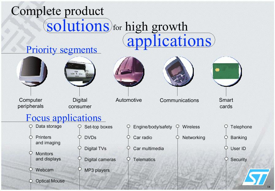
6 ST applications

7 ST and SOCs
8 ADS ST design kit deliveries 0.35u 0.25u 0.18u 0.13u BiCMOS6G BiCMOS7 RFCMOS8 HCMOS8D HCMOS9GP BiCMOS Available Under development IFF + Dynamic Link + ADS schematic capture Dynamic Link version only
9 Outline ❽ STMicroelectronics at a glance ❽ STV0399 Satellite Tuner description Specifications, Architecture, Layout, Board ❽ ADS platform ❽ Simulation results ❽ Conclusion
10 Motivation ❽ To simulate a whole front-end RF of a single chip satellite tuner for digital TV At system level: To specify RF block parameters To verify RFIC / Digital blocks interface To study digital feedback equalization loop At electrical level: To evaluate performance degradation with transistor level blocks ❽ To define and validate a design flow based on Agilent Advanced Design System simulators
11 ❽ ❽ Satellite Tuner Description Challenging Design Objective: Fully integrated tuner from RF signals to decoded digital data Very low cost external components Low cost CMOS process (0.18u) Integrated System Architecture: Analog/RF design constraints traded with digital architecture RF/analog blocks, ADC,digital blocks, frequency synthesizers ❽ Main features: Input frequency bandwidth: MHz Zero IF integration Multi standard link (B/Q/8 PSK) : symbol rate from 1 to 30 Mbauds Analog part (including ADC and PLL): devices Digital part: 200K Gates, Clock frequency up to 150MHz
12 Block diagram 900 MHz W 2150 MHz LNA Loop through AGC cos(ζt) sin(ζt) Low Pass Filter & AGC Low Pass Filter & AGC I Q A/D A/D Nyquist Filter + Derotator + 8PSK/QPSK/BPSK Demodulator AGC Control Forward Error Correction = Viterbi Deinterleaver + Reed Solomon Zero Intermediate Frequency (ZIF) MPEG Stream Architecture with AGC equalization
13 STV0399 board RF input to MPEG data stream RF Test (I,Q) STV0399 MPEG Loop-Through Very few external components Board size = 60mm x 45mm (die size = 16 mm2) Very low sensitivity to other RF signals 27 MHz crystal Crolles

14 STV0399 chip picture
15 Outline ❽ STMicroelectronics at a glance ❽ STV0399 Satellite Tuner description ❽ ADS platform Digital co-simulation Circuit envelope ❽ Simulation results ❽ Conclusion
")
 domain for")

16 Agilent Ptolemy ❽ ❽ ❽ Based on the Ptolemy code from UC Berkeley ADS Ptolemy uses the Synchronous Dataflow (SDF) domain for Digital Signal Processing analysis Agilent enhancements: Timed Synchronous Dataflow (TSDF) domain for RFIC co-simulation (Envelope) Large library of behavioral and timedomain models for newest communication standards I/O Interfaces: Matlab, VHDL
17 ADS Ptolemy Data Flow Domains ❽ ❽ Synchronous Data Flow domain Tokens (data units) are consumed (inputs) and produced (outputs) by each actor (functional block) Schedule is constructed once and repeatedly executed Digital simulator is launched for each arriving input token during a pre-defined time step Timed Synchronous Data Flow domain Timed data tokens produced from a timed actor are equally spaced in time Timed data type that can represent a signal as an envelope and carrier frequency (f c ), just like Transient and Circuit Envelope
18 ADS Co-simulation - I/O Interfaces C++ Matlab HDL RFIC SDF Models TSDF Agilent Ptolemy top-level description ADS Ptolemy simulations can incorporate: ❽ ❽ ❽ ❽ VHDL code by launching Mentor Graphics ModelSim or Cadence Verilog-XL + NCsim digital simulators Matlab models C++ code RFIC or transistor level simulators using ADS Envelope or Transient simulators

19 ADS and ModelSim GUI
 analysis provides the initial condition at t=0 Modified HB equations are solved independently in the time domain, generating a complex")
20 ADS Circuit Envelope ❽ ❽ ❽ ❽ To co-simulate with transistor level description Each input signal is converted into a Fund. harmonic + a time-varying envelope An Harmonic Balance (HB) analysis provides the initial condition at t=0 Modified HB equations are solved independently in the time domain, generating a complex envelope for each frequency t0 t1 t2 t3 Harmonic Balance t4 time fm coupling Fourier series with time-varying (digitally modulated) coefficients N j k t v(t) = real V (t)e k = 0 k ω fn
21 Outline ❽ STMicroelectronics at a glance ❽ STV0399 Satellite Tuner description ❽ ADS platform ❽ Simulation results System level simulations Circuit level simulations ❽ Conclusion
 sin(ζt) Low Pass Filter & AGC A/D Nyquist Filter Derotator 8PSK/QPSK/BPSK Demodulator AGC Control Forward Error Correction =")
22 System simulation of the STV0399 Simulation of the entire signal path from input MPEG bits to output MPEG bits into a single simulation environment MPEG 2 data Encoder Modulator B/QPSK/8PSK Fc=1 to 2GHz BW=1to30Msps LNA AGC Low Pass Filter & A/D AGC ADS Ptolemy cos(ζt) sin(ζt) Low Pass Filter & AGC A/D Nyquist Filter Derotator 8PSK/QPSK/BPSK Demodulator AGC Control Forward Error Correction = Viterbi Deinterleaver + Reed Solomon VHDL: VHDL: ModelSim ModelSim or NCSim MPEG Stream Error Estimation Spectrum Constellation
23 Transmission characteristics Q EVM: Error Vector Magnitude + BER: Bit Error Rate I C/N Estimator Carrier to Noise Estimator is computed internally by the digital part using a look-up table. It can be correlated to SNR: > SNR = 23dB
24 Simulation vs. Measurement Carrier to Noise Estimator versus symbol rate compared with DVB_S standard C/N estimator vs. symbol rate STV0399 with F synthe = 108 MHz Digital Video Broadcasting (DVB) standard C/N estimator Symbol rate (Mbauds)
25 Parasitic noise simulation Symbol rate = 4 Mbauds Time = symbols C/N Estimator AGC0 Control Signal C/N = MHz bandwidth noise added (-25 dbc) Input Spectrum Output Constellation
26 Parasitic noise simulation Time = symbols for each symbol rate ADS simulations C/N estimator Symbol rate (Mbauds) Symbol rate (Mbauds) Measurement
27 Clock spurious 27 MHz crystal

28 Clock spurious Symbol rate = 27.5 Mbauds Time = symbols PLL spectrum Spurious F crystal = 27 MHz F rate = 27.5 MHz Some spurious appear at 500 khz and degrade the performances. Input spectrum Output constellation
29 Clock spurious ADS simulations with spurious ADS simulations without spurious C/N = 3331 C/N estimator Symbol rate (Mbauds) Symbol rate (Mbauds) Measurement

30 Phase noise simulation Symbol rate = 6.25 Mbauds Time = symbols Spec C/N Estimator C/N = 2372 AGC0 Control Signal Measurement Measured phase noise was added in ADS simulations Input Spectrum Output Constellation
31 Circuit simulation of the STV0399 Simulation of the entire signal path from input MPEG bits to output MPEG bits into a single simulation environment MPEG 2 data Encoder Modulator BPSK/QPSK/8PSK Fc=1 to 2GHz BW=1 to 30Msps ADS Ptolemy LNA AGC Low Pass Filter & A/D AGC cos(ζt) sin(ζt) ADS Envelope : transistor level Low Pass Filter & AGC A/D Nyquist Filter Derotator BPSK/QPSK/8PSK Demodulator AGC Control Forward Error Correction = Viterbi Deinterleaver + Reed Solomon VHDL: VHDL: ModelSim ModelSim or NCSim MPEG Stream Error Estimation Spectrum Constellation
32 Circuit simulation of the STV0399 MPEG 2 data Encoder Modulator B/QPSK/8PSK Fc=1 to 2GHz BW=1to30Msps ADS Ptolemy RFIC Dynamic Link LNA AGC cos(ζt) sin(ζt) ADS Envelope : transistor level Low Pass Filter & AGC Low Pass Filter & AGC EnvOut Selector A/D A/D The EnvOut selector allows to choose the carrier frequency Cadence database IFF translation ADS ADS database


33 Circuit simulation : time-domain results Input bit stream I channel MPEG 2 data Encoder Modulator B/QPSK/8PSK Fc=1 to 2GHz BW=1to30Msps LNA AGC cos(ζt) sin(ζt) Low Pass Filter & AGC Low Pass Filter & AGC Q channel ADS Ptolemy Modulated signal ADS Envelope : transistor level
34 Circuit level simulation Aim : To see «real life» designs impact on performances. BUT real time consuming task CPU Time Ratio System level amplifier 1 x = 47 mn Transistor level amplifier 29 x Find a trade-off between speed and accuracy
35 Behavioral models Aim : To save time without loss of accuracy 0 db switch 6 db switch 12 db switch 18 db switch Used accurate table-based models derived from standard simulations CPU Time Ratio System level amplifier 1 x «Model» level amplifier 1.6 x
36 What we learnt ❽ Agilent Advanced Design System let simulate a whole front-end RF of a satellite receiver for digital TV At system level using ADS Ptolemy SDF and ModelSim VHDL simulators At electrical level using ADS Envelope simulator and table based behavioral models to speed-up simulation Good correlation between simulation and measurements Improved the design itself Allowed to explain some problems found in measurement phase
37 What we learnt ❽ However, simulation times are still very long for BER estimation including phase noise and RFIC co-simulation ❽ Need Agilent tools to easily extract table-based models ❽ Next ST developments using ADS as reference platform: cable, terrestrial, home television wireless distribution (HiperLAN2: 6GHz WLAN)...
Bridging the Gap between System & Circuit Designers
 Bridging the Gap between System & Circuit Designers October 27, 2004 Presented by: Kal Kalbasi Q & A Marc Petersen Copyright 2003 Agilent Technologies, Inc. The Gap System Communication System Design System
Chapter 6. Case Study: 2.4-GHz Direct Conversion Receiver. 6.1 Receiver Front-End Design
 Chapter 6 Case Study: 2.4-GHz Direct Conversion Receiver The chapter presents a 0.25-µm CMOS receiver front-end designed for 2.4-GHz direct conversion RF transceiver and demonstrates the necessity and
26.8: A 1.9GHz Single-Chip CMOS PHS Cellphone
 26.8: A 1.9GHz Single-Chip CMOS PHS Cellphone William W. Si, Srenik Mehta, Hirad Samavati, Manolis Terrovitis, Michael Mack, KeithOnodera, SteveJen, Susan Luschas, Justin Hwang, SuniMendis, DavidSu, BruceWooley
TSEK02: Radio Electronics Lecture 8: RX Nonlinearity Issues, Demodulation. Ted Johansson, EKS, ISY
 TSEK02: Radio Electronics Lecture 8: RX Nonlinearity Issues, Demodulation Ted Johansson, EKS, ISY 2 RX Nonlinearity Issues, Demodulation RX nonlinearities (parts of 2.2) System Nonlinearity Sensitivity
Behzad Razavi, RF Microelectronics, Prentice Hall PTR, 1998
 2008/Sep/17 1 Text Book: Behzad Razavi, RF Microelectronics, Prentice Hall PTR, 1998 References: (MSR) Thomas H. Lee, The Design of CMOS Radio-Frequency Integrated Circuits, 2/e, Cambridge University Press,
TSEK02: Radio Electronics Lecture 8: RX Nonlinearity Issues, Demodulation. Ted Johansson, EKS, ISY
 TSEK02: Radio Electronics Lecture 8: RX Nonlinearity Issues, Demodulation Ted Johansson, EKS, ISY RX Nonlinearity Issues: 2.2, 2.4 Demodulation: not in the book 2 RX nonlinearities System Nonlinearity
Using GoldenGate to Verify and Improve Your Designs Using Real Signals
 Using GoldenGate to Verify and Improve Your Designs Using Real Signals Enabling more complete understanding of your designs Agilent EEsof EDA 1 Outline What problems do designers face? Main point of this
Final Circuit & System Simulation - with Optional
 Final Circuit & System Simulation - with Optional Co-Simulation Slide 9-1 What is the final topic in this class? Simulation of your amp_1900 and filters in the receiver system to verify analog performance.
From Antenna to Bits:
 From Antenna to Bits: Wireless System Design with MATLAB and Simulink Cynthia Cudicini Application Engineering Manager MathWorks cynthia.cudicini@mathworks.fr 1 Innovations in the World of Wireless Everything
Payload measurements with digital signals. Markus Lörner, Product Management Signal Generation Dr. Susanne Hirschmann, Signal Processing Development
 Payload measurements with digital signals Markus Lörner, Product Management Signal Generation Dr. Susanne Hirschmann, Signal Processing Development Agenda ı Why test with modulated signals? ı Test environment
Case Study: and Test Wireless Receivers
 Case Study: Using New Technologies to Design and Test Wireless Receivers Agenda Architecture of a receiver Basic GPS Receiver Measurements Case Study 1: GPS Simulation How Testing Works Simulation vs.
Session 3. CMOS RF IC Design Principles
 Session 3 CMOS RF IC Design Principles Session Delivered by: D. Varun 1 Session Topics Standards RF wireless communications Multi standard RF transceivers RF front end architectures Frequency down conversion
ISSCC 2006 / SESSION 33 / MOBILE TV / 33.4
 33.4 A Dual-Channel Direct-Conversion CMOS Receiver for Mobile Multimedia Broadcasting Vincenzo Peluso, Yang Xu, Peter Gazzerro, Yiwu Tang, Li Liu, Zhenbiao Li, Wei Xiong, Charles Persico Qualcomm, San
Cosimulating Synchronous DSP Applications with Analog RF Circuits
 Presented at the Thirty-Second Annual Asilomar Conference on Signals, Systems, and Computers - November 1998 Cosimulating Synchronous DSP Applications with Analog RF Circuits José Luis Pino and Khalil
Thank you for downloading one of our ANSYS whitepapers we hope you enjoy it.
 Thank you! Thank you for downloading one of our ANSYS whitepapers we hope you enjoy it. Have questions? Need more information? Please don t hesitate to contact us! We have plenty more where this came from.
TSTE17 System Design, CDIO. General project hints. Behavioral Model. General project hints, cont. Lecture 5. Required documents Modulation, cont.
 TSTE17 System Design, CDIO Lecture 5 1 General project hints 2 Project hints and deadline suggestions Required documents Modulation, cont. Requirement specification Channel coding Design specification
Research and Development Activities in RF and Analog IC Design. RFIC Building Blocks. Single-Chip Transceiver Systems (I) Howard Luong
 Howard Luong") Research and Development Activities in RF and Analog IC Design Howard Luong Analog Research Laboratory Department of Electrical and Electronic Engineering Hong Kong University of Science and Technology
Research and Development Activities in RF and Analog IC Design Howard Luong Analog Research Laboratory Department of Electrical and Electronic Engineering Hong Kong University of Science and Technology
Verification of the RF Subsystem within Wireless LAN System Level Simulation
 Verification of the RF Subsystem within Wireless LAN System Level Simulation Uwe Knöchel Thomas Markwirth Fraunhofer IIS, Dept. EAS Dresden, Germany uwe.knoechel@eas.iis.fhg.de Jürgen Hartung Cadence Design
D2.5. Description of MaMi digital modulation and architectures for efficient MaMi transmission MAMMOET. 36 months FP7/ WP 2
 This project has received funding from the European Union s Seventh Framework Programme for research, technological development and demonstration under grant agreement no 619086. D2.5 Description of MaMi
RF/IF Terminology and Specs
 RF/IF Terminology and Specs Contributors: Brad Brannon John Greichen Leo McHugh Eamon Nash Eberhard Brunner 1 Terminology LNA - Low-Noise Amplifier. A specialized amplifier to boost the very small received
An FPGA Case Study: Narrowband COFDM Video Transceiver for Drones, UAV, and UGV. Produced by EE Times
 An FPGA Case Study: Narrowband COFDM Video Transceiver for Drones, UAV, and UGV #eelive Produced by EE Times An FPGA Case Study System Definition Implementation Verification and Validation CNR1 Narrowband
SETTING UP A WIRELESS LINK USING ME1000 RF TRAINER KIT
 SETTING UP A WIRELESS LINK USING ME1000 RF TRAINER KIT Introduction S Kumar Reddy Naru ME Signal Processing S. R. No - 05812 The aim of the project was to try and set up a point to point wireless link.
22. VLSI in Communications
 22. VLSI in Communications State-of-the-art RF Design, Communications and DSP Algorithms Design VLSI Design Isolated goals results in: - higher implementation costs - long transition time between system
TSEK38 Radio Frequency Transceiver Design: Project work B
 TSEK38 Project Work: Task specification A 1(15) TSEK38 Radio Frequency Transceiver Design: Project work B Course home page: Course responsible: http://www.isy.liu.se/en/edu/kurs/tsek38/ Ted Johansson (ted.johansson@liu.se)
The wireless industry
 From May 2007 High Frequency Electronics Copyright Summit Technical Media, LLC RF SiP Design Verification Flow with Quadruple LO Down Converter SiP By HeeSoo Lee and Dean Nicholson Agilent Technologies
2002 IEEE International Solid-State Circuits Conference 2002 IEEE
 Outline 802.11a Overview Medium Access Control Design Baseband Transmitter Design Baseband Receiver Design Chip Details What is 802.11a? IEEE standard approved in September, 1999 12 20MHz channels at 5.15-5.35
LOW NOISE BLOCKDOWN CONVERTER
 LOW NOISE BLOCKDOWN CONVERTER Europe: LNB for Broadcasting Satellite (1) Wide band type receiving all broadcasting channels (analog & digital) of Europe. [Universal LNB] (2) Originally developed feed-horn
Agilent EEsof EDA.
 Agilent EEsof EDA This document is owned by Agilent Technologies, but is no longer kept current and may contain obsolete or inaccurate references. We regret any inconvenience this may cause. For the latest
Understanding Low Phase Noise Signals. Presented by: Riadh Said Agilent Technologies, Inc.
 Understanding Low Phase Noise Signals Presented by: Riadh Said Agilent Technologies, Inc. Introduction Instabilities in the frequency or phase of a signal are caused by a number of different effects. Each
EXPERIMENT WISE VIVA QUESTIONS
 EXPERIMENT WISE VIVA QUESTIONS Pulse Code Modulation: 1. Draw the block diagram of basic digital communication system. How it is different from analog communication system. 2. What are the advantages of
120W UHF Transmitter/Repeater
 Product Features 470 MHz - 860 MHz Broadband Transmitter/Repeater LDMOS Power Amplifier provides 120 Watt output for ATSC, ATSC-M/H, CMMB, DTMB, DVB-T/H, DVB-T2, DVB-SH, ISDB-T/TB,, DAB, DAB+ and T-DMB
Keysight Technologies Understanding the SystemVue To ADS Simulation Bridge. Application Note
 Keysight Technologies Understanding the To Simulation Bridge Application Note Introduction The Keysight Technologies, Inc. is a new system-level design environment that enables a top-down, model-based
VLSI Chip Design Project TSEK01
 VLSI Chip Design Project TSEK01 Project description and requirement specification Version 1.0 Project: 250mW ISM Band Class D/E Power Amplifier Project number: 4 Project Group: Name Project members Telephone
A 65nm CMOS RF Front End dedicated to Software Radio in Mobile Terminals
 A 65nm CMOS RF Front End dedicated to Software Radio in Mobile Terminals F. Rivet, Y. Deval, D. Dallet, JB Bégueret, D. Belot IMS Laboratory, Université de Bordeaux, Talence, France STMicroelectronics,
Antenna Measurements using Modulated Signals
 Antenna Measurements using Modulated Signals Roger Dygert MI Technologies, 1125 Satellite Boulevard, Suite 100 Suwanee, GA 30024-4629 Abstract Antenna test engineers are faced with testing increasingly
Advanced Design System - Fundamentals. Mao Wenjie
 Advanced Design System - Fundamentals Mao Wenjie wjmao@263.net Main Topics in This Class Topic 1: ADS and Circuit Simulation Introduction Topic 2: DC and AC Simulations Topic 3: S-parameter Simulation
Advanced RF Measurements You Didn t Know Your Oscilloscope Could Make. Brad Frieden Philip Gresock
 Advanced RF Measurements You Didn t Know Your Oscilloscope Could Make Brad Frieden Philip Gresock Agenda RF measurement challenges Oscilloscope platform overview Typical RF characteristics Bandwidth vs.
VLSI Chip Design Project TSEK06
 VLSI Chip Design Project TSEK06 Project Description and Requirement Specification Version 1.1 Project: 100 MHz, 10 dbm direct VCO modulating FM transmitter Project number: 4 Project Group: Name Project
LNS ultra low phase noise Synthesizer 8 MHz to 18 GHz
 LNS ultra low phase noise Synthesizer 8 MHz to 18 GHz Datasheet The LNS is an easy to use 18 GHz synthesizer that exhibits outstanding phase noise and jitter performance in a 3U rack mountable chassis.
Analog and Telecommunication Electronics
 Politecnico di Torino Electronic Eng. Master Degree Analog and Telecommunication Electronics C5 - Synchronous demodulation» AM and FM demodulation» Coherent demodulation» Tone decoders AY 2015-16 19/03/2016-1
Optimized BPSK and QAM Techniques for OFDM Systems
 I J C T A, 9(6), 2016, pp. 2759-2766 International Science Press ISSN: 0974-5572 Optimized BPSK and QAM Techniques for OFDM Systems Manikandan J.* and M. Manikandan** ABSTRACT A modulation is a process
DEVELOPMENT OF A DIGITAL TERRESTRIAL FRONT END
 DEVELOPMENT OF A DIGITAL TERRESTRIAL FRONT END ABSTRACT J D Mitchell (BBC) and P Sadot (LSI Logic, France) BBC Research and Development and LSI Logic are jointly developing a front end for digital terrestrial
Adoption of this document as basis for broadband wireless access PHY
 Project Title Date Submitted IEEE 802.16 Broadband Wireless Access Working Group Proposal on modulation methods for PHY of FWA 1999-10-29 Source Jay Bao and Partha De Mitsubishi Electric ITA 571 Central
MODELING AND SIMULATION FOR RF SYSTEM DESIGN
 MODELING AND SIMULATION FOR RF SYSTEM DESIGN Modeling and Simulation for RF System Design by RONNY FREVERT Fraunhofer Institute for Integrated Circuits, Dresden, Germany JOACHIM HAASE Fraunhofer Institute
Wavedancer A new ultra low power ISM band transceiver RFIC
 Wavedancer 400 - A new ultra low power ISM band transceiver RFIC R.W.S. Harrison, Dr. M. Hickson Roke Manor Research Ltd, Old Salisbury Lane, Romsey, Hampshire, SO51 0ZN. e-mail: roscoe.harrison@roke.co.uk
ISSCC 2003 / SESSION 20 / WIRELESS LOCAL AREA NETWORKING / PAPER 20.5
 ISSCC 2003 / SESSION 20 / WIRELESS LOCAL AREA NETWORKING / PAPER 20.5 20.5 A 2.4GHz CMOS Transceiver and Baseband Processor Chipset for 802.11b Wireless LAN Application George Chien, Weishi Feng, Yungping
SPECIFICATION. DVB-C / Worldwide NIM Tuner
 1.Feature * All-in-one full NIM function with compact size, optimal solution for cost reduction and shortening product development lead-time. * ITU J.83 Annex A/C and DVB-C (ETSI EN 300 429) compliant
DVB-S2 Demodulator VHDL RTL/structural Macro
 Technical Specifications DVB-S2 Demodulator VHDL RTL/structural Macro DVB-S2 Macro is a DVB-S2 Demodulator VHDL design capable of Demodulating, on a single FPGA device of a suitable family, in CCM, VCM
High Data Rate QPSK Modulator with CCSDS Punctured FEC channel Coding for Geo-Imaging Satellite
 International Journal of Advances in Engineering Science and Technology 01 www.sestindia.org/volume-ijaest/ and www.ijaestonline.com ISSN: 2319-1120 High Data Rate QPSK Modulator with CCSDS Punctured FEC
Modeling Your Systems in ADS
 Modeling Your Systems in ADS Challenges for Aerospace and Defense Applications Custom signal formats required for design & testing Bring user s IP in ADS Unique signal processing Evaluating and Modeling
COMTECH TECHNOLOGY CO., LTD. DVBS SPECIFICATION
 1.SCOPE The DVBS2-6899 supports QPSK in DIRECTV and DVB-S legacy transmission (up to 45 Mbauds), plus 8PSK in DVB-S2 transmissions (up to 30 Mbauds). DVB-S2 demodulation uses robust symbols probust by
CMOS RFIC ARCHITECTURES FOR IEEE NETWORKS
 CMOS RFIC ARCHITECTURES FOR IEEE 82.15.4 NETWORKS John Notor, Anthony Caviglia, Gary Levy Cadence Design Systems, Inc. 621 Old Dobbin Lane, Suite 1 Columbia, Maryland 2145, USA 23 IEEE CMOS RFIC ARCHITECTURES
BPSK_DEMOD. Binary-PSK Demodulator Rev Key Design Features. Block Diagram. Applications. General Description. Generic Parameters
 Key Design Features Block Diagram Synthesizable, technology independent VHDL IP Core reset 16-bit signed input data samples Automatic carrier acquisition with no complex setup required User specified design
Reconfigurable and Simultaneous Dual Band Galileo/GPS Front-end Receiver in 0.13µm RFCMOS
 Reconfigurable and Simultaneous Dual Band Galileo/GPS Front-end Receiver in 0.13µm RFCMOS A. Pizzarulli 1, G. Montagna 2, M. Pini 3, S. Salerno 4, N.Lofu 2 and G. Sensalari 1 (1) Fondazione Torino Wireless,
Multiple Reference Clock Generator
 A White Paper Presented by IPextreme Multiple Reference Clock Generator Digitial IP for Clock Synthesis August 2007 IPextreme, Inc. This paper explains the concept behind the Multiple Reference Clock Generator
TV Test Receiver EFA, Models 40/43 (DVB-T)
") TV Test Receiver EFA, Models 40/43 (DVB-T) Comprehensive analysis/demodulation/monitoring of digital terrestrial TV signals All DVB-T modes supported according to ETS300744 High-end demodulator High-end
TV Test Receiver EFA, Models 40/43 (DVB-T) Comprehensive analysis/demodulation/monitoring of digital terrestrial TV signals All DVB-T modes supported according to ETS300744 High-end demodulator High-end
3250 Series Spectrum Analyzer
 The most important thing we build is trust ADVANCED ELECTRONIC SOLUTIONS AVIATION SERVICES COMMUNICATIONS AND CONNECTIVITY MISSION SYSTEMS 3250 Series Spectrum Analyzer > Agenda Introduction
MODELING AND SIMULATION FOR RF SYSTEM DESIGN
 MODELING AND SIMULATION FOR RF SYSTEM DESIGN Modeling and Simulation for RF System Design by RONNY FREVERT Fraunhofer Institute for Integrated Circuits, Dresden, Germany JOACHIM HAASE Fraunhofer Institute
Addressing the Challenges of Wideband Radar Signal Generation and Analysis. Marco Vivarelli Digital Sales Specialist
 Addressing the Challenges of Wideband Radar Signal Generation and Analysis Marco Vivarelli Digital Sales Specialist Agenda Challenges of Wideband Signal Generation Challenges of Wideband Signal Analysis
Crest Factor Reduction
 June 2007, Version 1.0 Application Note 396 This application note describes crest factor reduction and an Altera crest factor reduction solution. Overview A high peak-to-mean power ratio causes the following
PGT313 Digital Communication Technology. Lab 3. Quadrature Phase Shift Keying (QPSK) and 8-Phase Shift Keying (8-PSK)
 and 8-Phase Shift Keying (8-PSK)") PGT313 Digital Communication Technology Lab 3 Quadrature Phase Shift Keying (QPSK) and 8-Phase Shift Keying (8-PSK) Objectives i) To study the digitally modulated quadrature phase shift keying (QPSK) and
PGT313 Digital Communication Technology Lab 3 Quadrature Phase Shift Keying (QPSK) and 8-Phase Shift Keying (8-PSK) Objectives i) To study the digitally modulated quadrature phase shift keying (QPSK) and
Simulation of Radio Frequency Integrated Circuits
 Simulation o Radio Frequency Integrated Circuits Based on: Computer-Aided Circuit Analysis Tools or RFIC Simulation: Algorithms, Features, and Limitations, IEEE Trans. CAS-II, April 2000. Outline Introduction
High-Performance Analog and RF Circuit Simulation using the Analog FastSPICE Platform at Columbia University. Columbia University
 High-Performance Analog and RF Circuit Simulation using the Analog FastSPICE Platform at Columbia University By: K. Tripurari, C. W. Hsu, J. Kuppambatti, B. Vigraham, P.R. Kinget Columbia University For
Digital Signal Analysis
 Digital Signal Analysis Objectives - Provide a digital modulation overview - Review common digital radio impairments Digital Modulation Overview Signal Characteristics to Modify Polar Display / IQ Relationship
Keysight Technologies
 Keysight Technologies Generating Signals Basic CW signal Block diagram Applications Analog Modulation Types of analog modulation Block diagram Applications Digital Modulation Overview of IQ modulation
CMOS Analog to Digital Converters : State-of-the-Art and Perspectives in Digital Communications ADC
 CMOS Analog to Digital Converters : State-of-the-Art and Perspectives in Digital Communications ADC Hussein Fakhoury and Hervé Petit C²S Research Group Presentation Outline Introduction Basic concepts
GSM Transmitter Modulation Quality Measurement Option
 Performs all required measurements for GSM transmitters Outputs multiple time mask parameters for process control analysis Obtains frequency error, rms phase error, and peak phase error with one command
Outline / Wireless Networks and Applications Lecture 3: Physical Layer Signals, Modulation, Multiplexing. Cartoon View 1 A Wave of Energy
 Outline 18-452/18-750 Wireless Networks and Applications Lecture 3: Physical Layer Signals, Modulation, Multiplexing Peter Steenkiste Carnegie Mellon University Spring Semester 2017 http://www.cs.cmu.edu/~prs/wirelesss17/
Exploring Trends in Technology and Testing in Satellite Communications
 Exploring Trends in Technology and Testing in Satellite Communications Aerospace Defense Symposium Giuseppe Savoia Keysight Technologies Agenda Page 2 Evolving military and commercial satellite communications
Technical Article A DIRECT QUADRATURE MODULATOR IC FOR 0.9 TO 2.5 GHZ WIRELESS SYSTEMS
 Introduction As wireless system designs have moved from carrier frequencies at approximately 9 MHz to wider bandwidth applications like Personal Communication System (PCS) phones at 1.8 GHz and wireless
MIMO RFIC Test Architectures
 MIMO RFIC Test Architectures Christopher D. Ziomek and Matthew T. Hunter ZTEC Instruments, Inc. Abstract This paper discusses the practical constraints of testing Radio Frequency Integrated Circuit (RFIC)
Understanding Probability of Intercept for Intermittent Signals
 2013 Understanding Probability of Intercept for Intermittent Signals Richard Overdorf & Rob Bordow Agilent Technologies Agenda Use Cases and Signals Time domain vs. Frequency Domain Probability of Intercept
Today s mobile devices
 PAGE 1 NOVEMBER 2013 Highly Integrated, High Performance Microwave Radio IC Chipsets cover 6-42 GHz Bands Complete Upconversion & Downconversion Chipsets for Microwave Point-to-Point Outdoor Units (ODUs)
Satellite Communications: Part 4 Signal Distortions & Errors and their Relation to Communication Channel Specifications. Howard Hausman April 1, 2010
 Satellite Communications: Part 4 Signal Distortions & Errors and their Relation to Communication Channel Specifications Howard Hausman April 1, 2010 Satellite Communications: Part 4 Signal Distortions
FEATURES DESCRIPTION BENEFITS APPLICATIONS. Preliminary PT4501 Sub-1 GHz Wideband FSK Transceiver
 Preliminary PT4501 Sub-1 GHz Wideband FSK Transceiver DESCRIPTION The PT4501 is a highly integrated wideband FSK multi-channel half-duplex transceiver operating in sub-1 GHz license-free ISM bands. The
PORTING OF AN FPGA BASED HIGH DATA RATE DVB-S2 MODULATOR
 Proceedings of the SDR 11 Technical Conference and Product Exposition, Copyright 2011 Wireless Innovation Forum All Rights Reserved PORTING OF AN FPGA BASED HIGH DATA RATE MODULATOR Chayil Timmerman (MIT
A 1.7-to-2.2GHz Full-Duplex Transceiver System with >50dB Self-Interference Cancellation over 42MHz Bandwidth
 A 1.7-to-2.2GHz Full-Duplex Transceiver System with >50dB Self-Interference Cancellation Tong Zhang, Ali Najafi, Chenxin Su, Jacques C. Rudell University of Washington, Seattle Feb. 8, 2017 International
Commsonic. DVB-C/J.83 Cable Demodulator CMS0022. Contact information
 DVB-C/J.83 Cable Demodulator CMS0022 DVB-C EN 300 429 ITU J83 Annexes A/B/C DOCSIS 1.1 / 2.0 IF sub-sampling or I/Q baseband interface. Standard 188-byte MPEG Transport Stream output. Variable ADC width
A 1.9GHz Single-Chip CMOS PHS Cellphone
 A 1.9GHz Single-Chip CMOS PHS Cellphone IEEE JSSC, Vol. 41, No.12, December 2006 William Si, Srenik Mehta, Hirad Samavati, Manolis Terrovitis, Michael Mack, Keith Onodera, Steve Jen, Susan Luschas, Justin
High-Linearity CMOS. RF Front-End Circuits
 High-Linearity CMOS RF Front-End Circuits Yongwang Ding Ramesh Harjani iigh-linearity CMOS tf Front-End Circuits - Springer Library of Congress Cataloging-in-Publication Data A C.I.P. Catalogue record
SiNANO-NEREID Workshop:
 SiNANO-NEREID Workshop: Towards a new NanoElectronics Roadmap for Europe Leuven, September 11 th, 2017 WP3/Task 3.2 Connectivity RF and mmw Design Outline Connectivity, what connectivity? High data rates
LTE: System Specifications and Their Impact on RF & Base Band Circuits Application Note
 LTE: System Specifications and Their Impact on RF & Base Band Circuits Application Note Products: R&S FSW R&S SMU R&S SFU R&S FSV R&S SMJ R&S FSUP RF physical layer specifications (such as 3GPP TS36.104)
SIMULATION AND IMPLEMENTATION OF LOW POWER QPSK ON FPGA Tushar V. Kafare*1 *1( E&TC department, GHRCEM Pune, India.)
") www.ardigitech.inissn 2320-883X, VOLUME 1 ISSUE 4, 01/10/2013 SIMULATION AND IMPLEMENTATION OF LOW POWER QPSK ON FPGA Tushar V. Kafare*1 *1( E&TC department, GHRCEM Pune, India.) tusharkafare31@gmail.com*1
www.ardigitech.inissn 2320-883X, VOLUME 1 ISSUE 4, 01/10/2013 SIMULATION AND IMPLEMENTATION OF LOW POWER QPSK ON FPGA Tushar V. Kafare*1 *1( E&TC department, GHRCEM Pune, India.) tusharkafare31@gmail.com*1
ADI 2006 RF Seminar. Chapter VI A Detailed Look at Wireless Signal Chain Architectures
 DI 2006 R Seminar Chapter VI Detailed Look at Wireless Chain rchitectures 1 Receiver rchitectures Receivers are designed to detect and demodulate the desired signal and remove unwanted blockers Receiver
Direct-Conversion I-Q Modulator Simulation by Andy Howard, Applications Engineer Agilent EEsof EDA
 Direct-Conversion I-Q Modulator Simulation by Andy Howard, Applications Engineer Agilent EEsof EDA Introduction This article covers an Agilent EEsof ADS example that shows the simulation of a directconversion,
ADI 2006 RF Seminar. Chapter II RF/IF Components and Specifications for Receivers
 ADI 2006 RF Seminar Chapter II RF/IF Components and Specifications for Receivers 1 RF/IF Components and Specifications for Receivers Fixed Gain and Variable Gain Amplifiers IQ Demodulators Analog-to-Digital
A 1.55 GHz to 2.45 GHz Center Frequency Continuous-Time Bandpass Delta-Sigma Modulator for Frequency Agile Transmitters
 RMO2C A 1.55 GHz to 2.45 GHz Center Frequency Continuous-Time Bandpass Delta-Sigma Modulator for Frequency Agile Transmitters RFIC 2009 Martin Schmidt, Markus Grözing, Stefan Heck, Ingo Dettmann, Manfred
mm-wave Transceiver Challenges for the 5G and 60GHz Standards Prof. Emanuel Cohen Technion
 mm-wave Transceiver Challenges for the 5G and 60GHz Standards Prof. Emanuel Cohen Technion November 11, 11, 2015 2015 1 mm-wave advantage Why is mm-wave interesting now? Available Spectrum 7 GHz of virtually
Challenges in Designing CMOS Wireless System-on-a-chip
 Challenges in Designing CMOS Wireless System-on-a-chip David Su Atheros Communications Santa Clara, California IEEE Fort Collins, March 2008 Introduction Outline Analog/RF: CMOS Transceiver Building Blocks
SYSTEM ARCHITECTURE ADVANCED SYSTEM ARCHITECTURE LUO Chapter18.1 and Introduction to OFDM
 SYSTEM ARCHITECTURE ADVANCED SYSTEM ARCHITECTURE LUO Chapter18.1 and 18.2 Introduction to OFDM 2013/Fall-Winter Term Monday 12:50 Room# 1-322 or 5F Meeting Room Instructor: Fire Tom Wada, Professor 12/9/2013
USE OF MATLAB IN SIGNAL PROCESSING LABORATORY EXPERIMENTS
 USE OF MATLAB SIGNAL PROCESSG LABORATORY EXPERIMENTS R. Marsalek, A. Prokes, J. Prokopec Institute of Radio Electronics, Brno University of Technology Abstract: This paper describes the use of the MATLAB
VERIFICATION OF RECEIVER EQUALIZATION BY INTEGRATING DATAFLOW SIMULATION AND PHYSICAL CHANNELS. A Thesis. presented to.
 VERIFICATION OF RECEIVER EQUALIZATION BY INTEGRATING DATAFLOW SIMULATION AND PHYSICAL CHANNELS A Thesis presented to the Faculty of California Polytechnic State University, San Luis Obispo In Partial Fulfillment
June 09, 2014 Document Version: 1.1.0
 DVB-T2 Analysis Toolkit Data Sheet An ideal solution for SFN network planning, optimization, maintenance and Broadcast Equipment Testing June 09, 2014 Document Version: 1.1.0 Contents 1. Overview... 3
ELT Radio Architectures and Signal Processing. Motivation, Some Background & Scope
 Introduction ELT-44007/Intro/1 ELT-44007 Radio Architectures and Signal Processing Motivation, Some Background & Scope Markku Renfors Department of Electronics and Communications Engineering Tampere University
Design Considerations for 5G mm-wave Receivers. Stefan Andersson, Lars Sundström, and Sven Mattisson
 Design Considerations for 5G mm-wave Receivers Stefan Andersson, Lars Sundström, and Sven Mattisson Outline Introduction to 5G @ mm-waves mm-wave on-chip frequency generation mm-wave analog front-end design
RADIO RECEIVERS ECE 3103 WIRELESS COMMUNICATION SYSTEMS
 RADIO RECEIVERS ECE 3103 WIRELESS COMMUNICATION SYSTEMS FUNCTIONS OF A RADIO RECEIVER The main functions of a radio receiver are: 1. To intercept the RF signal by using the receiver antenna 2. Select the
Fully integrated UHF RFID mobile reader with power amplifiers using System-in-Package (SiP)
") Fully integrated UHF RFID mobile reader with power amplifiers using System-in-Package (SiP) Hyemin Yang 1, Jongmoon Kim 2, Franklin Bien 3, and Jongsoo Lee 1a) 1 School of Information and Communications,
Fully integrated UHF RFID mobile reader with power amplifiers using System-in-Package (SiP) Hyemin Yang 1, Jongmoon Kim 2, Franklin Bien 3, and Jongsoo Lee 1a) 1 School of Information and Communications,
Multiband multistandard direct-conversion TV tuner
 SPECIFICATION 1 FEATURES TSMC 0.18 um SiGe BiCMOS technology Direct conversion receiver A few number of external components 0.18 um SiGe BiCMOS technology Integrated 75 Ω input matched LNAs Integrated
TD-SCDMA DesignGuide May 2007
 TD-SCDMA DesignGuide May 2007 Notice The information contained in this document is subject to change without notice. Agilent Technologies makes no warranty of any kind with regard to this material, including,
Wireless Communication Systems: Implementation perspective
 Wireless Communication Systems: Implementation perspective Course aims To provide an introduction to wireless communications models with an emphasis on real-life systems To investigate a major wireless