Agilent EEsof EDA.
|
|
|
- Hilda Armstrong
- 6 years ago
- Views:
Transcription
1 Agilent EEsof EDA This document is owned by Agilent Technologies, but is no longer kept current and may contain obsolete or inaccurate references. We regret any inconvenience this may cause. For the latest information on Agilent s line of EEsof electronic design automation (EDA) products and services, please go to:
2 Advanced Design System for Wireline and High Speed Analog Design Tuesday, May 21, 2002Title of Page 1
3 TRENDS AND CHALLENGES ADS VALUE ADS DESIGN FLOW SOLUTIONS PRODUCT OFFERINGS CONCLUSIONS Page 2
4 The need for ADS in Wireline Most optical systems contain 80% electronics. Waguih Ishak Technology director Agilent Communications and Optics Networks Lab Page 3
5 High-speed Lightwave Transmission Switching and Routing Semiconductors (SRS) 10 Gbit/s Transmitter Clock Optical Transport Semiconductors (OTS) Laser Driver nm (long haul) 850 nm (short haul, board level) Optical Components (OC) Laser CMOS Data Source 16:1 Mux 622 MB/s 10 GB/s Re-timing circuit Modulator Driver Modulator Fiber Optic Channel CPU 622 MB/s 1:16 DMux 10 GB/s Limiting Amp TIA Photo Detector Receiver Det Page 4
6 TRENDS AND CHALLENGES FEC = Forward Error Correction Multi-Rate Support (FEC) Power Dissipation Block Diagram Integration CMOS Data Source FEC Coding Gain improves BER CPU Clock 16:1 622 MB/s Mux 10 GB/s 622 MB/s Jitter (VCO Phase Noise) Multi-Rate Support (FEC) 6-7Vpp drive level at high freq Power Dissipation Waveform distortion / dispersion Active Device Model 1:16 DMux High-Speed Integration Power Dissipation 10 GB/s Det Laser Driver TIA Laser BiCMOS GaAs HBT SiGe - infrastructure InP - instrumentation Power Control Eye Quality RZ Modulation for Long Haul Modulator Photo Detector Tunable Laser Optical Signal Separation Dynamic range of modulator Electrical / Optical interface Fiber Attenuation Chromatic Dispersion (CD) Polarization Mode Dispersion Optical Non-linearities Sensitivity, Dynamic Range Signal Detect Accuracy Optical-Electrical Integration Page 5
7 TRENDS AND CHALLENGES ADS VALUE Applications Simulations ADS DESIGN FLOW SOLUTIONS PRODUCT OFFERINGS CONCLUSIONS Page 6
8 Benefits of ADS / IC-CAP for Wireline Leading edge simulation technologies Time Domain / Frequency Domain / EM / Optimization under one environment IC package analysis Board analysis Foundry partners for latest models Design Flow - Cadence Dynamic Link Active Device Model capability (IC-CAP) Page 7
9 Application Examples Reference design examples Page 8
10 Multiplexer 16:1 MUX 2:1 MUX 2:1 MUX 2:1 MUX 2:1 MUX 2:1 MUX 2:1 MUX 2:1 MUX 2:1 Data Selector Data Selector Data Selector Data Selector Data Selector Data Selector ADS can be used to design complete MUX/DEMUX Data Selector Amplifier Design Challenges: Signal Timing Jitter Eye diagram Good Impedance match Page 9


11 Laser Modulator ADS can be used to design electrical portions of the Laser Modulator Design Challenges: CPW Bond Wire model Optical Measured Data Good Impedance match Page 10
12 Modulator Driver Laser Driver Laser Mod. Driver Optical Modulator ADS can be used to design complete MUX/DEMUX Design Challenge: High Speed Signal and Large Output Signal Requirements Short rise time and Fall time requirements for good eye Opening Minimal Jitter ( Phase Noise) Good impedance match Wide Bandwidth design Page 11
13 Limiting Amplifier Limiting Amplifier ADS can be used to design Limiting Amplifier for 10 GB/s and 40 GB/s system Limiting Amplifier is the main amplifier in OC-192 & OC768 Limiting Amplifier is used to reshape NRZ data Design Challenges: Ultra wide bandwidth with High gain Minimum Phase shift deviation to achieve small timing jitter Output Power must be constant over a wide dynamic range Page 12
14 Amplifier with Gain Control Variable Amplifier ADS can be used to design Variable Gain Amplifier Design Challenges: Linear channel flat response over very wide bandwidth Constant group delay throughout band Good input and output return loss Wide gain control dynamic range Low noise figure design Page 13
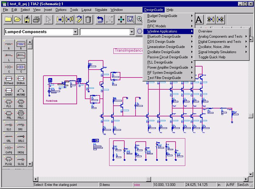
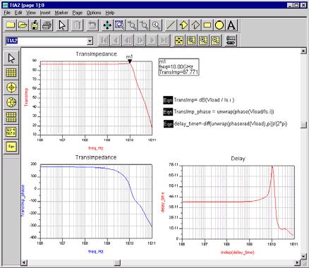
15 Trans-Impedance Amplifier Trans-Imp. Amplifier ADS can be used to design Trans-Impedance Amplifier Design Challenges: High Gain over wide Bandwidth High Speed with wide Dynamic Range To achieve lowest possible noise while retaining Bandwidth performance Good Input/Output Return Loss Low Power Consumption Effects of distributed models Include measured S-Parameters from Network analysers or EM simulators Include E/O measurements of laser, detector from Agilent Lightwave analysers. Create and use a behavioral model from simulation or from Data Sheet Create and use an Encoded Model of the TIA Page 14


16 OEIC Package Design Uses ADS Capability On chip signal distribution, Vias, Coplanar waveguide, Multilayer structures, Spiral Inductors, Bond Wires BGA and other packages Page 15
17 TRENDS AND CHALLENGES ADS VALUE Applications Simulations ADS DESIGN FLOW SOLUTIONS PRODUCT OFFERINGS CONCLUSIONS Page 16
18 High Frequency Spice with Convolution Analysis In standard Spice all the frequency-dependent components are approximated with lumped element equivalents High frequency effects such as dispersion and loss at higher frequencies are not taken into account The Convolution engine in ADS High Frequency Spice models accurately all frequency-dependent components (microstrip, S-parameter blocks etc.) Impulse response for all distributed components is calculated, then convolved with input signal to yield output Y ( s) X ( s) H ( s) y( t) x( t) h( t ) d t 0 Unique in ADS Page 17

19 ADS Simulation of Transimpedance Amplifier (TIA) or Laser Driver Time Domain (using High Frequency Spice and Convolution Simulator) Jitter, Gain, Skew, delay, Eye diagram, Eye Closure Rise time, overshoot, ringing etc. Effects of distributed models of on chip transmission lines and Packages such as BGA Page 18

20 ADS Simulation of Transimpedance Amplifier (TIA), or Laser Driver Time Domain (using High Frequency Spice and Convolution Simulator) Differential circuits and LVDS Include measured S-Parameters from Network analysers or other sources such as EM simulators Include E/O measurements of laser, detector from Agilent Lightwave analysers. Use a behavioral model of TIA from simulation or from Data Sheet Create and use an Encoded Model of the TIA Page 19
21 ADS Simulation of Oscillator and Clock Recovery circuits Time Domain (using High Frequency Spice and Convolution Simulator) Jitter, Oscillator start up time, Waveform, Rise time, overshoot, ringing etc. Effects of distributed models of on chip transmission lines and Package such as BGA Include measured S-Parameters from Network analysers or other sources such as EM simulators Create and use an Encoded Model of the Oscillator Page 20


22 ADS Simulation of Oscillator and Clock Recovery circuits Frequency Domain (Linear and Non-Linear Harmonic Balance, and Circuit Envelope Simulator) Loop gain and phase in Oscillator circuit, Oscillating frequency, level, waveform and spectrum. Ring Oscillators. Phase Noise VS frequency offset Jitter Calculated from Phase Noise PLL circuits, Lock time, Frequency vs Time Effects of distributed models (transmission lines, vias etc) of on chip transmission lines and Package such as BGA Include measured S-Parameters from Network analysers or other sources such as EM simulators Create and use a behavioral model of Oscillator from simulation or from Data Sheet Create and use an Encoded Model of the Oscillator Page 21
23 Harmonic Balance Operation V V j CV 0 R V V, V... V ) ( 1 2 k The circuit is described by deriving Kirchoff s current law in the frequency domain at each node The system of nonlinear equations so obtained is solved using the Newton-Raphson method Since most nonlinear devices are described by time domain (Spice) models, the simulator has to transform (inverse FFT) the voltage spectrum into the time domain, evaluate the response of the device then transform it back to the frequency domain (FFT) Page 22


24 HB Oscillator Analysis Phase Noise Simulation FM Flicker noise 1/f 3 Pts/decade FM white noise 1/f 2 PM Flicker noise 1/f PM White noise Start Stop Page 23
25 Transient-Assisted Harmonic Balance How it works: Runs transient to generate an initial guess Initial guess is transformed from time to frequency domain Use the initial guess with harmonic balance Applications: Highly nonlinear analog/rf circuits Digital circuits (i.e. dividers, phase detectors) Available in ADS Unique in ADS Page 24

26 TAHB Example Divide by 8 chain of three flip-flops CMOS, 76 MOSFETs examine phase noise after division Run times, P3-500 transient: 96 sec HB signal: 21 sec HB noise: 122 sec for 4 phase noise analyses Page 25


27 ADS Simulation of IC and PC Board structures Distributed Models and EM simulation In Time or Frequency Domain. PC Board transmission lines and traces, multilayer vias and routing LVDS traces and signals Creating lumped element equivalent models of all of the above. TAPERED LINES MULTI- COUPLED LINES COUPLED CROSSOVER COUPLE D CORNER S Page 26


28 Agilent Ptolemy Unique in ADS Based on the Ptolemy code from UC Berkeley Simulation environment that supports multiple domains ADS Ptolemy uses the Synchronous Dataflow (SDF) domain for Digital Signal Processing analysis We have added: Timed Synchronous Dataflow (TSDF) domain for co-simulation Large library of behavioral and timedomain models I/O Interfaces Page 27
29 TRENDS AND CHALLENGES ADS VALUE ADS DESIGN FLOW SOLUTIONS PRODUCT OFFERINGS CONCLUSIONS Page 28
) db(s(1,2)) 20")


30 Electronic Design Tools ADS, IC-CAP db(s(2,1)) db(s(1,2)) freq, GHz frequency domain view (S 11, S 22 etc.), Non-linear response modelled interconnect. LVDS laser driver with transmission lines time domain view of data and crosstalk Simulation of Clock Phase noise and Jitter Page 29
31 A World Class Integrated Simulation Tools Linear Harmonic Balance Krylov Solver Transient Assisted HB Circuit Envelope Convolution High Frequency SPICE RF System Simulator Ptolemy Ptolemy Fixed Point Digital Filter E-Syn Domain Physical Numeric Time Frequency AC / S-Parameters HF SPICE High Speed Interconnect Library New Harmonic Balance Convolution Momentum Circuit Envelope Ptolemy Synchronous Dataflow Model Composer Ptolemy Timed Synchronous Dataflow (TSDF) Planar EM Advancing Capabilities Page 30
32 ADS Foundry Support SiGe GaAs HBT GaAs HBT Maxim GST2 & MBIC-1 Clock Optical Transport Semiconductors (OTS) BiCMOS SiGe HBT GaAs HBT Laser Driver SiGe - infrastructure InP - instrumentation TQTRx 0.18um & 0.25um CMOS 16:1 Mux 10 GB/s Re-timing circuit 0.18um & 0.25um CMOS 5AM, 5HP, 6HP & 7HP SiGe BiCMOS SiGe HBT GaAs HBT SiGe - infrastructure InP - instrumentation HCMOS7 0.25um & HCMOS8 0.13um BICMOS 6M & SiGe 6G 0.35um 1:16 DMux 10 GB/s TIA 0.8u BYX SiGe QBIC3 & QBIC4 Det Page 31
33 ADS Design Flow with Cadence Dynamic Link Cadence Dynamic Link ADS schematic layout Simulations Design Kit DRC / LVS Harmonic Balance Design Kit Parasitic extraction Transient Convolution DesignGuides Interconnect Models Planar EM Post Processing Ptolemy Page 32

34 xxx xx xxx xxx xxx x xx xxx x xxx x xxx xxx xx xxx xxx xxxx xxx x xxx xxxx IC-CAP Parameter Extraction Methodology for Accurate Device Models Support extraction of industry standard and customized simulation models Open environment customizable to each process Characterize process variations with statistical modeling Modeling System Test Setups Measured Data IC-CAP Integrated Circuit Characterization and Analysis Program Model Parameters XXXXXXX Model Libraries Circuit Design Device Design Process Control Page 33
35 TRENDS AND CHALLENGES ADS VALUE ADS DESIGN FLOW SOLUTIONS PRODUCT OFFERINGS CONCLUSIONS Page 34
36 PRODUCT SOLUTIONS HIGH SPEED ANALOG DESIGNER PRODUCT BUNDLES HSAD HSAD Pro HSAD Premier Design Environment X X X Data Display X X X Linear Simulator X X X High Frequency Spice X X X Spice Netlist Translator X X X Passive Circuit DesignGuide X X X Convolution Simulator X X Multi-Layer interonnect Models X X Statistical Design X X RF Passive Circuit Models X X Layout X X Layout Translators X X Momentum X X Momentum Visualization X X Momentum Optimization X Harmonic Balance X RF System Models X Ptolemy X Ptolemy Matrix Models X Analog Model Development X E-Syn X Page 35
37 E9008A - Agilent High Speed Analog Design Simulation Technology Accurate devices and distributed transmission line models for 40 GB/s design. Linear Simulators to evaluate small signal Performance. Harmonic Balance Simulator for accurate output power characterization and Optimization. Spice and Convolution time domain simulators for accurate time domain simulation for 10 GB/s and 40 GB/s designs. EM simulation capability in integrated environment for package characterization and interconnect modeling. Interconnect Model library. Ptolemy Simulator and Matrix Models Design Flow Design kits supportfrom many commercial foundry. Powerful data processing capabilities for circuit performance characterization. Integrated environment for system and circuit design. Page 36
38 TRENDS AND CHALLENGES ADS VALUE ADS DESIGN FLOW SOLUTIONS PRODUCT OFFERINGS CONCLUSIONS Page 37
39 Accurate and Efficient High Speed Analog Design Model 10 & 40 Gb/s with ADS Trans-Impedance Amplifier Distributed Travelling Wave Amplifier Limiting Amplifier Multiplexer/Demultiplexer Design Laser Driver Modulator Driver (large voltage swings) Variable gain Amplifier Variable Attenuators Ring Oscillator (jitter) Clock Recovery Circuit (jitter) Error correction encoders & decoders Interconnect & Package Design Semiconductor Parameters and More.. Page 38
40 ADS Simulation Capabilites for Optical Wireline Summary Frequency and time domain simulators: Pick the right tool for the job at hand Can do much more than Spice Distributed models and EM simulation Account for high frequency effects that can no longer be ignored Do System, on board, and IC all in one tool Combine everything for end to end simulation with all physical effects Complete Simulation of Transmit and Receive sections Eye Diagram/Eye Closure Jitter Measurements/Transfer Functions Page 39
41 ADS Capabilities Additional Slides
42 DC Analysis Operation Capacitors, inductors eliminated Topology checked for circuits with no unique DC solution Iteratively find solution such that sum of all DC currents into each circuit node is zero Uses Newton-Raphson convergence algorithm to find solution for nonlinear devices (BJTs, FETs, diodes) Sum of DC currents must be zero Page 41
43 AC/S-Parameter Analysis DC analysis is performed to find the bias point Nonlinear devices linearized at the bias point Assumes signal does not perturb the bias Components characterized by their small-signal [S] or [Y] Finds solution such that sum of all AC currents into each circuit node is zero (not iterative) Computes [S] and [Y] of the overall circuit at external ports Calculates response to small sinusoidal signals Page 42
44 Transient Analysis (SPICE) - Simple RC Circuit Kirchoff s current equations are derived at each node in differential form v(t) v( t) R C dv( t) dt 0 (1) The time derivatives are replaced with discrete-time approximations (integration) The solution in the case of a complex circuit will consist of a system of nonlinear equations which is solved using the Newton-Raphson method Page 43
45 HB Nonlinear Noise Analysis Large signals at harmonics Small signals on either side harmonics large signals and non-linearities causes mixing Noise from nf translates to IF LO f IF Noise from all components translates to output 0 IF LO RF 2LO 3LO Page 44
46 Phase Noise as Frequency Modulation All oscillators exhibit sensitivity of oscillation frequency to voltage (VCO) Noise acts to randomly modulate the oscillator frequency db/dec Hz 10 khz 1 MHz Page 45
47 Phase Noise Mixing Noise mixes with oscillator harmonics fosc 2fosc 3fosc 100 Hz 10 khz 1 MHz Page 46
48 TAHB example (2) Transceiver-on-chip: includes RF, analog and digital circuitry Total # of Devices = 14, ,000+ linear devices including interconnect and substrate parasitics non-linear devices 400 BJT s, 60 MOSFET s, 800 diodes Single-tone analysis with 56 harmonics 4.5 hours on an HP J210 workstation with 1GB of RAM Page 47
49 Spice Vs Harmonic Balance: ADS has them BOTH Standard Spice Solves KCL by Newton Raphson Time Steps determine rise time resolution Error Residuals determine Accuracy Frequencies determined by Fourrier transform-needs long sim. period Standard Spice Models Used Used for decades by Analog and Digital designers Can t simulate non-linear noise such as phase noise ADS HFSPICE CAN SIMULATE JITTER! Harmonic Balance Solves KCL by Newton Raphson # of Harmonics determine rise time resolution Error Residuals Determine Accuracy Frequencies solved for explicitly. Standard Spice Models used Used for decades by RF and Microwave designer. Excellent for non-linear noise and phase noise. Page 48
50 What ADS can Simulate in Transimpedance Amplifier (TIA) or Laser Driver Frequency Domain (Linear and Non-Linear Harmonic Balance Simulator) Effects of distributed models (transmission lines, vias etc) of on chip transmission lines and Package such as BGA, Crosstalk, Bounce Include measured S-Parameters from Network analysers or other sources such as EM simulators Include E/O measurements of laser, detector from Agilent Lightwave analysers. Create and use a behavioral model of TIA from simulation or from Data Sheet Create and use an Encoded Model of the TIA Page 49
51 What ADS can Simulate in Mux/Demux and SerDes circuits Time Domain (using High Frequency Spice and Convolution Simulator) Jitter, Rise time, overshoot, ringing etc. Skew, delay Effects of distributed models of on chip transmission lines and Package such as BGA Include measured S-Parameters from Network analysers or other sources such as EM simulators Create and use an Encoded Model of the circuit Create and use behavioral digital model using Ptolemy (instead of transistor level circuit) Page 50
52 What ADS can Simulate in Mux/Demux and SerDes circuits Frequency Domain Using Harmonic balance (TAHB) Additive Phase noise Additive Jitter calculated from Phase noise Page 51

53 What ADS can Simulate in Data Source, Encoding and Error Correction circuits Ptolemy Data flow Simulator Develop and create algorithms Implement as high level functional circuits and gates Generate and output HDL Use in end to end simulation of physical layer by cosimulating with analog circuits Page 52
54 What ADS can Simulate in IC and PC Board structures: EVAL, DUT, and Demo boards Simulate IC on Board Isolate IC and Board effects Correlate simulation with measurements On Evaluation Boards in R&D On DUT boards in Manufacturing Test On customer DEMO boards Page 53
55 For more information about Agilent EEsof EDA, visit: Agilent Updates Get the latest information on the products and applications you select. Agilent Direct Quickly choose and use your test equipment solutions with confidence. For more information on Agilent Technologies products, applications or services, please contact your local Agilent office. The complete list is available at: Americas Canada (877) Latin America United States (800) Asia Pacific Australia China Hong Kong India Japan 0120 (421) 345 Korea Malaysia Singapore Taiwan Thailand Europe & Middle East Austria Belgium 32 (0) Denmark Finland 358 (0) France * *0.125 /minute Germany ** **0.14 /minute Ireland Israel /544 Italy Netherlands 31 (0) Spain 34 (91) Sweden Switzerland United Kingdom 44 (0) Other European Countries: Revised: March 27, 2008 Product specifications and descriptions in this document subject to change without notice. Agilent Technologies, Inc. 2008
EM Insights Series. Episode #1: QFN Package. Agilent EEsof EDA September 2008
 EM Insights Series Episode #1: QFN Package Agilent EEsof EDA September 2008 Application Overview Typical situation IC design is not finished until it is packaged. It is now very important for IC designers
Agilent EEsof EDA.
 Agilent EEsof EDA This document is owned by Agilent Technologies, but is no longer kept current and may contain obsolete or inaccurate references. We regret any inconvenience this may cause. For the latest
UWB Antenna Measurements with the 20 GHz E5071C ENA Network Analyzer
 UWB Antenna Measurements with the 20 GHz E5071C ENA Network Analyzer Application Note Minimize cost of test with the 20 GHz ENA s high performance and fast measurement speed Quickly leverage your current
Agilent EEsof EDA.
 Agilent EEsof EDA This document is owned by Agilent Technologies, but is no longer kept current and may contain obsolete or inaccurate references. We regret any inconvenience this may cause. For the latest
Fundamentals of RF Design RF Back to Basics 2015
 Fundamentals of RF Design 2015 Updated January 1, 2015 Keysight EEsof EDA Objectives Review Simulation Types Understand fundamentals on S-Parameter Simulation Additional Linear and Non-Linear Simulators
Radar System Design and Interference Analysis Using Agilent SystemVue
 Radar System Design and Interference Analysis Using Agilent SystemVue Introduction Application Note By David Leiss, Sr. Consultant EEsof EDA Anurag Bhargava, Application Engineer EEsof EDA Agilent Technologies
Agilent U9397A/C FET Solid State Switches (SPDT)
") Agilent U9397A/C FET Solid State Switches (SPDT) U9397A 300 khz to 8 GHz U9397C 300 khz to 18 GHz Technical Overview Key Features Prevent damage to sensitive components with low video leakage < 10 mvpp
Agilent U9397A/C FET Solid State Switches (SPDT) U9397A 300 khz to 8 GHz U9397C 300 khz to 18 GHz Technical Overview Key Features Prevent damage to sensitive components with low video leakage < 10 mvpp
Two-Way Radio Testing with Agilent U8903A Audio Analyzer
 Two-Way Radio Testing with Agilent U8903A Audio Analyzer Application Note Introduction As the two-way radio band gets deregulated, there is a noticeable increase in product offerings in this area. What
Agilent N8480 Series Thermocouple Power Sensors. Technical Overview
 Agilent N8480 Series Thermocouple Power Sensors Technical Overview Introduction The new N8480 Series power sensors replace and surpass the legacy 8480 Series power sensors (excluding the D-model power
ADS-SystemVue Linkages
 ADS-SystemVue Linkages Uniting System, Baseband, and RF design flows for leading-edge designs Superior RF models and simulators Convenient, polymorphic algorithmic modeling, debug, and test May 2010 Page
MEMS On-wafer Evaluation in Mass Production Testing At the Earliest Stage is the Key to Lowering Costs
 MEMS On-wafer Evaluation in Mass Production Testing At the Earliest Stage is the Key to Lowering Costs Application Note Recently, various devices using MEMS technology such as pressure sensors, accelerometers,
Optical Modulator Driver Amplifier
 Preliminary data sheet for Optical Modulator Driver Amp. Optical Modulator Driver Amplifier MDA-1-8S Features Wide Bandwidth: 3kHz 15GHz Rise Time: 15 ps Eye Amplitude: 7.5 pp Accepts RZ input signal Crossover
Keysight Technologies Understanding the SystemVue To ADS Simulation Bridge. Application Note
 Keysight Technologies Understanding the To Simulation Bridge Application Note Introduction The Keysight Technologies, Inc. is a new system-level design environment that enables a top-down, model-based
MMIC/RFIC Packaging Challenges Webcast (July 28, AM PST 12PM EST)
") MMIC/RFIC Packaging Challenges Webcast ( 9AM PST 12PM EST) Board Package Chip HEESOO LEE Agilent EEsof 3DEM Technical Lead 1 Agenda 1. MMIC/RFIC packaging challenges 2. Design techniques and solutions
MMIC/RFIC Packaging Challenges Webcast ( 9AM PST 12PM EST) Board Package Chip HEESOO LEE Agilent EEsof 3DEM Technical Lead 1 Agenda 1. MMIC/RFIC packaging challenges 2. Design techniques and solutions
Advanced Design System - Fundamentals. Mao Wenjie
 Advanced Design System - Fundamentals Mao Wenjie wjmao@263.net Main Topics in This Class Topic 1: ADS and Circuit Simulation Introduction Topic 2: DC and AC Simulations Topic 3: S-parameter Simulation
ISSCC 2006 / SESSION 13 / OPTICAL COMMUNICATION / 13.2
 13.2 An MLSE Receiver for Electronic-Dispersion Compensation of OC-192 Fiber Links Hyeon-min Bae 1, Jonathan Ashbrook 1, Jinki Park 1, Naresh Shanbhag 2, Andrew Singer 2, Sanjiv Chopra 1 1 Intersymbol
Agilent HMMC-3124 DC-12 GHz Packaged High Efficiency Divide-by-4 Prescaler 1GC TR1-7" diameter reel/500 each 1GC BLK-bubble strip/10 each
 Agilent HMMC-3124 DC-12 GHz Packaged High Efficiency Divide-by-4 Prescaler 1GC1-8207-TR1-7" diameter reel/500 each 1GC1-8207-BLK-bubble strip/10 each Data Sheet Features Wide Frequency Range: 0.2-12 GHz
Agilent Correlation between TDR oscilloscope and VNA generated time domain waveform
 Agilent Correlation between TDR oscilloscope and VNA generated time domain waveform Application Note Introduction Time domain analysis (TDA) is a common method for evaluating transmission lines and has
Agilent AN Balanced Circuit Measurement with an Impedance Analyzer/LCR Meter/Network Analyzer Application Note
 Agilent AN 346-2 Balanced Circuit Measurement with an Impedance Analyzer/LCR Meter/Network Analyzer Application Note Introduction How a balanced circuit differs from an unbalanced circuit A balanced circuit
Appendix. Harmonic Balance Simulator. Page 1
 Appendix Harmonic Balance Simulator Page 1 Harmonic Balance for Large Signal AC and S-parameter Simulation Harmonic Balance is a frequency domain analysis technique for simulating distortion in nonlinear
Agilent N8973A, N8974A, N8975A NFA Series Noise Figure Analyzers. Data Sheet
 Agilent N8973A, N8974A, N8975A NFA Series Noise Figure Analyzers Data Sheet Specifications Specifications are only valid for the stated operating frequency, and apply over 0 C to +55 C unless otherwise
Agilent U1881A and U1882A Power Measurement Application for Agilent InfiniiVision and Infiniium Oscilloscopes
 Agilent U1881A and U1882A Power Measurement Application for Agilent InfiniiVision and Infiniium Oscilloscopes Data Sheet Fast, automatic and reliable characterization of switching mode power devices Today
Agilent 87405B. Preamplifier 10 MHz to 4 GHz. Technical Overview. Features. Benchtop/General Purpose Use
 Agilent 8705B Preamplifier 10 MHz to GHz Technical Overview Features db Gain 5 db Noise Figure Probe-power bias connection via probe port from Agilent s spectrum analyzers Compact Size Benchtop/General
Agilent EEsof EDA.
 Agilent EEsof EDA This document is owned by Agilent Technologies, but is no longer kept current and may contain obsolete or inaccurate references. We regret any inconvenience this may cause. For the latest
A Time-Saving Method for Analyzing Signal Integrity in DDR Memory Buses
 A Time-Saving Method for Analyzing Signal Integrity in DDR Memory Buses Application Note 1591 This application note covers new tools and measurement techniques for characterizing and validating signal
Satellite Tuner Single Chip Simulation with Advanced Design System
 Turning RF IC technology into successful design Satellite Tuner Single Chip Simulation with Advanced Design System Cédric Pujol - Central R&D March 2002 STMicroelectronics Outline ❽ STMicroelectronics
Solutions for Solar Cell and Module Testing
 Solutions for Solar Cell and Module Testing Agilent 663XB Power Supplies Connected in Anti-Series to Achieve Four-Quadrant Operation for Solar Cell and Module Testing Application Note Overview To fully
Making a S11 and S21 Measurement Using the Agilent N9340A
 Making a S11 and S21 Measurement Using the Agilent N9340A Application Note Introduction Spectrum characteristics are important in wireless communication system maintenance. Network and spectrum analyzers
Agilent NFA Noise Figure Analyzer
 Agilent NFA Noise Figure Analyzer Configuration Guide Dedicated Noise Figure Analyzer Hard specifications to 26.5 GHz Works with N4000A SNS or 346 Series noise sources Noise figure measurements to 110
Techniques to Achieve Oscilloscope Bandwidths of Greater Than 16 GHz
 Techniques to Achieve Oscilloscope Bandwidths of Greater Than 16 GHz Application Note Infiniium s 32 GHz of bandwidth versus techniques other vendors use to achieve greater than 16 GHz Banner specifications
 Using a Network and Impedance Analyzer to Evaluate 13.56 MHz RFID Tags and Readers/Writers Silicon Investigations Repair Information - Contact Us 920-955-3693 www.siliconinvestigations.com Application
Multipurpose Lab Station by Agilent Technologies
 Multipurpose Lab Station by Agilent Technologies The Agilent Multipurpose Lab Station is an integrated system comprised of a: 1 2 3 4 5 6 7 8 Mixed signal oscilloscope (MSO) or digital signal oscilloscope
Process Control Calibration Made Easy with Agilent U1401A
 Process Control Calibration Made Easy with Agilent U1401A Application Note This application note explains how the Agilent U1401A with simultaneous source and measure functions eases technicians calibration
7 Hints That Every Engineer Should Know When Making Power Measurements with Oscilloscopes.
 7 Hints That Every Engineer Should Know When Making Power Measurements with Oscilloscopes. Achieving maximized measurement dynamic range 1) Use averaging to increase measurement resolution 2) Use high-resolution
 Agilent PN 4395-1 Agilent 4395A Network/Spectrum/ Impedance Analyzer Silicon Investigations Repair Information - Contact Us 920-955-3693 www.siliconinvestigations.com ADSL Copper Loop Measurements Product
Agilent N9310A RF Signal Generator. All the capability and reliability of an Agilent instrument you need at a price you ve always wanted
 Agilent N9310A RF Signal Generator All the capability and reliability of an Agilent instrument you need at a price you ve always wanted Reliable Performance. Essential Test Capability The N9310A RF signal
N9051A Pulse Measurement Software
 N9051A Pulse Measurement Software X-Series Signal Analyzers and PSA Series Spectrum Analyzers Technical Overview Characterize pulse performance using a wide range of parameters including pulse width, rise/fall
Agilent Spectrum Visualizer (ASV) Software. Data Sheet
 Software. Data Sheet") Agilent Spectrum Visualizer (ASV) Software Data Sheet Technical Overview The Agilent spectrum visualizer (ASV) software provides advanced FFT frequency domain analysis for the InfiniiVision and Infiniium
Agilent Spectrum Visualizer (ASV) Software Data Sheet Technical Overview The Agilent spectrum visualizer (ASV) software provides advanced FFT frequency domain analysis for the InfiniiVision and Infiniium
N2790A 100 MHz, N2791A 25 MHz and N2891A 70 MHz High-voltage Differential Probes
 N2790A 100 MHz, N2791A 25 MHz and N2891A 70 MHz High-voltage Differential Probes Data Sheet Oscilloscope users often need to make floating measurements where neither point of the measurement is at earth
Agilent N9342C Handheld Spectrum Analyzer (HSA)
") Agilent N9342C Handheld Spectrum Analyzer (HSA) Data Sheet Field testing just got easier The Agilent N9342C handheld spectrum analyzer (HSA) is more than easy-to-use its measurement performance gives you
Agilent N9342C Handheld Spectrum Analyzer (HSA) Data Sheet Field testing just got easier The Agilent N9342C handheld spectrum analyzer (HSA) is more than easy-to-use its measurement performance gives you
Agilent EEsof EDA. Enabling First Pass Success. Chee Keong, Teo Business Development Manager EEsof South Asia. Agilent Restricted
 Agilent EEsof EDA Enabling First Pass Success Chee Keong, Teo Business Development Manager EEsof South Asia EEsof EDA is Strategic to Agilent Technologies As the world s premier measurement company, Agilent
Agilent N4000A, N4001A, N4002A SNS Series Noise Sources 10 MHz to 26.5 GHz
 Agilent N4000A, N4001A, N4002A SNS Series Noise Sources 10 MHz to 26.5 GHz Technical Overview Advances in Noise Figure Accuracy N4000A Used for low noise figure devices or devices sensitive to mismatch
Characterize Phase-Locked Loop Systems Using Real Time Oscilloscopes
 Characterize Phase-Locked Loop Systems Using Real Time Oscilloscopes Introduction Phase-locked loops (PLL) are frequently used in communication applications. For example, they recover the clock from digital
Agilent 2-Port and 4-Port PNA-X Network Analyzer
 Agilent 2-Port and 4-Port PNA-X Network Analyzer N5244A - MHz to 43.5 GHz N5245A - MHz to 5. GHz with Option H29 Data Sheet and Technical Specifications Documentation Warranty THE MATERIAL CONTAINED IN
Keysight Technologies Network Analyzer Measurements: Filter and Amplifier Examples. Application Note
 Keysight Technologies Network Analyzer Measurements: Filter and Amplifier Examples Application Note Introduction Both the magnitude and phase behavior of a component are critical to the performance of
Evaluating Oscilloscope Bandwidths for your Application
 Evaluating Oscilloscope Bandwidths for your Application Application Note 1588 Table of Contents Introduction....................... 1 Defining Oscilloscope Bandwidth..... 2 Required Bandwidth for Digital
Innovations in EDA Webcast Series
 Welcome Innovations in EDA Webcast Series August 2, 2012 Jack Sifri MMIC Design Flow Specialist IC, Laminate, Package Multi-Technology PA Module Design Methodology Realizing the Multi-Technology Vision
Agilent 87222C/D/E Coaxial Transfer Switches dc to 26.5, 40, 50 GHz
 Agilent 87C/D/E Coaxial Transfer Switches dc to 6.5, 0, 50 GHz Technical Overview High Performance Transfer Switches for Micro wave and RF Instrumentation and Systems Exceptional repeatability for more
Appendix. RF Transient Simulator. Page 1
 Appendix RF Transient Simulator Page 1 RF Transient/Convolution Simulation This simulator can be used to solve problems associated with circuit simulation, when the signal and waveforms involved are modulated
Agilent InfiniiMax III probing system
 Agilent InfiniiMax III probing system Data Sheet World s highest speed and highest performing probe system Full 30 GHz bandwidth to the probe tip Industry s lowest probe and scope system noise Industry
8 Hints for Better Spectrum Analysis. Application Note
 8 Hints for Better Spectrum Analysis Application Note 1286-1 The Spectrum Analyzer The spectrum analyzer, like an oscilloscope, is a basic tool used for observing signals. Where the oscilloscope provides
Agilent 8761A/B Microwave Switches
 Agilent 8761A/B Microwave Switches Technical Overview Product Description The Agilent Technologies 8761A and 8761B are single-pole, double-throw coaxial switches with excellent electrical and mechanical
Agilent 81180A Arbitrary Waveform Generator
 Agilent 81180A Arbitrary Waveform Generator Specification 1.0 When waveform resolution matters test with confidence 4.2 GSa/s Arbitrary Waveform Generator with 12 bit vertical resolution 1 81180A at a
Agilent MXG Signal Generators
 Agilent MXG Signal Generators N5161A MXG ATE Analog N5162A MXG ATE Vector N5181A MXG Analog N5182A MXG Vector Configuration Guide This guide is to assist in the ordering process for the MXG analog and
Agilent Nonlinear Vector Network Analyzer (NVNA)
") Agilent Nonlinear Vector Network Analyzer (NVNA) Breakthrough technology for nonlinear vector network analysis from 1 MHz to 67 GHz I know my amplifier gain is changing with output match, but Hot S22 measurements
Agilent Nonlinear Vector Network Analyzer (NVNA) Breakthrough technology for nonlinear vector network analysis from 1 MHz to 67 GHz I know my amplifier gain is changing with output match, but Hot S22 measurements
Keysight HMMC-1002 DC 50 GHz Variable Attenuator
 Keysight HMMC-1002 DC 50 GHz Variable Attenuator 1GG7-8001 Data Sheet Features Specified frequency range: DC to 26.5 GHz Return loss: 10 db Minimum attenuation: 2.0 db Maximum attenuation: 30.0 db 02 Keysight
Agilent 87075C Multiport Test Set
 Agilent 87075C Multiport Test Set Technical Overview A complete 75 Ω system for cable TV device manufacturers Now, focus on testing, not reconnecting! For use with the Agilent 8711 C-Series of network
Keysight Technologies Phase Noise X-Series Measurement Application
 Keysight Technologies Phase Noise X-Series Measurement Application N9068C Technical Overview Phase noise measurements with log plot and spot frequency views Spectrum and IQ waveform monitoring for quick
Keysight Technologies Solid State Switches. Application Note
 Keysight Technologies Solid State Switches Application Note Introduction Selecting the right switch technology for your application RF and microwave switches are used extensively in microwave systems for
Artisan Technology Group is your source for quality new and certified-used/pre-owned equipment
 Artisan Technology Group is your source for quality new and certified-used/pre-owned equipment FAST SHIPPING AND DELIVERY TENS OF THOUSANDS OF IN-STOCK ITEMS EQUIPMENT DEMOS HUNDREDS OF MANUFACTURERS SUPPORTED
Keysight Technologies VSA Software for Simulation Environments BE/89601 BNE
 Keysight Technologies 89600 VSA Software for Simulation Environments 89601 BE/89601 BNE 89601BE and 89601BNE are no longer orderable after December 2017 because the bundled capability of simulation link
12.5 Gb/s Driver Amplifier LABware Module PSPL8001 Datasheet
 12.5 Gb/s Driver Amplifier LABware Module PSPL8001 Datasheet The PSPL8001 12.5 Gb/s Driver Amplifier LABware Module is designed for bench-top lab use. This LABware module can simply be plugged in with
Keysight TC GHz High Power Output Amplifier
 Keysight TC724 2-26.5 GHz High Power Output Amplifier 1GG7-8045 Data Sheet Features Wide Frequency Range: 2 26.5 GHz Moderate Gain: 7.5 db Gain Flatness: ± 1 db Return Loss: Input: 17 db Output: 14 db
Agilent 8762F Coaxial Switch 75 ohm
 Agilent 8762F Coaxial Switch 75 ohm Technical Overview DC to 4 GHz Exceptional repeatability over 1 million cycle life Excellent isolation The 8762F brings a new standard of performance to 75 ohm coaxial
Agilent E5061B Network Analyzer. 100 khz to 1.5 GHz/3 GHz 5 Hz to 3 GHz
 Agilent E5061B Network Analyzer 100 khz to 1.5 GHz/3 GHz 5 Hz to 3 GHz E5061B responds to various measurement needs, - from LF to RF The Agilent E5061B is a member of the industry standard ENA Series network
Agilent EEsof EDA.
 Agilent EEsof EDA This document is owned by Agilent Technologies, but is no longer kept current and may contain obsolete or inaccurate references. We regret any inconvenience this may cause. For the latest
Keysight Technologies Accurate Capacitance Characterization at the Wafer Level
 Keysight Technologies Accurate Capacitance Characterization at the Wafer Level 4080 Series Parametric Test Systems Application Note Introduction The continuing trend of decreasing device geometries of
Keysight Technologies 7 Hints That Every Engineer Should Know When Making Power Measurements with Oscilloscopes. Application Note
 Keysight Technologies 7 Hints That Every Engineer Should Know When Making Power Measurements with Oscilloscopes Application Note Seven Hints for Making Power Measurements with Oscilloscopes Achieving maximized
Measuring Power Supply Switching Loss with an Oscilloscope
 Measuring Power Supply Switching Loss with an Oscilloscope Application Note Introduction With the demand for improving power efficiency and extending the operating time of battery-powered devices, the
Keysight Technologies N4983A Multiplexer and Demultiplexer. Data Sheet
 Keysight Technologies N4983A Multiplexer and Demultiplexer Data Sheet 02 Keysight N4983A Multiplexer and Demultiplexer - Data Sheet N4983A-M40 44 Gb/s multiplexer Features Wide operating range, 2 to 44
Agilent N9342C Handheld Spectrum Analyzer (HSA)
") Agilent N9342C Handheld Spectrum Analyzer (HSA) 100 khz to 7 GHz (tunable to 9 khz) Data Sheet Field testing just got easier www.agilent.com/find/hsa If you are making measurements in the field, the Agilent
Agilent N9342C Handheld Spectrum Analyzer (HSA) 100 khz to 7 GHz (tunable to 9 khz) Data Sheet Field testing just got easier www.agilent.com/find/hsa If you are making measurements in the field, the Agilent
Solar Array Simulation System Integration
 Solar Array Simulation System Integration Technical Overview When laying out the design of an E4360A solar array simulator (SAS) system, steps can be taken up front to ensure proper and reliable system
Agilent EEsof EDA.
 Agilent EEsof EDA This document is owned by Agilent Technologies, but is no longer kept current and may contain obsolete or inaccurate references. We regret any inconvenience this may cause. For the latest
U1881A and U1882A Power Measurement Application for InfiniiVision and Infiniium Oscilloscopes
 U1881A and U1882A Power Measurement Application for InfiniiVision and Infiniium Oscilloscopes Data Sheet Fast, automatic and reliable characterization of switching mode power devices Today s power supply
U1881A and U1882A Power Measurement Application for InfiniiVision and Infiniium Oscilloscopes
 U1881A and U1882A Power Measurement Application for InfiniiVision and Infiniium Oscilloscopes Data Sheet Fast, automatic and reliable characterization of switching mode power devices Today s power supply
Essential Capabilities of EMI Receivers. Application Note
 Essential Capabilities of EMI Receivers Application Note Contents Introduction... 3 CISPR 16-1-1 Compliance... 3 MIL-STD-461 Compliance... 4 Important features not required by CISPR 16-1-1 or MIL-STD-461...
Using GoldenGate to Verify and Improve Your Designs Using Real Signals
 Using GoldenGate to Verify and Improve Your Designs Using Real Signals Enabling more complete understanding of your designs Agilent EEsof EDA 1 Outline What problems do designers face? Main point of this
Agilent 4294A Precision Impedance Analyzer, 40 Hz to 110 MHz. Configuration Guide
 Agilent 4294A Precision Impedance Analyzer, 40 Hz to 110 MHz Configuration Guide Ordering Guide The following steps will guide you through configuring your 4294A. Standard Furnished Item CD-ROM Manual
Front-To-Back MMIC Design Flow with ADS. Speed MMICs to market Save money and achieve high yield
 Front-To-Back MMIC Design Flow with ADS Speed MMICs to market Save money and achieve high yield 1 Unique Tools for Robust Designs, First Pass, and High Yield Yield Sensitivity Histogram (YSH) to components
Agilent MXG Signal Generators
 Agilent MXG Signal Generators N5161A MXG ATE Analog N5162A MXG ATE Vector N5181A MXG Analog N5182A MXG Vector Configuration Guide This guide is to assist in the ordering process for the MXG analog and
Ansys Designer RF Training Lecture 3: Nexxim Circuit Analysis for RF
 Ansys Designer RF Solutions for RF/Microwave Component and System Design 7. 0 Release Ansys Designer RF Training Lecture 3: Nexxim Circuit Analysis for RF Designer Overview Ansoft Designer Advanced Design
Agilent NFA Noise Figure Analyzer
 Agilent NFA Noise Figure Analyzer Configuration Guide Dedicated Noise Figure Analyzer Hard specifications to 26.5 GHz Works with N4000A SNS or 346 Series noise sources Noise figure measurements to 110
Creating Arbitrary Waveforms in the U2300A Series and U2500A Series Data Acquisition Devices
 Creating Arbitrary Waveforms in the U2300A Series and U2500A Series Data Acquisition Devices Application Note Introduction The U2300A Series and U2500A Series data acquisition device (DAQ) families are
When is it Time to Transition to a Higher Bandwidth Oscilloscope?
 When is it Time to Transition to a Higher Bandwidth Oscilloscope? Application Note When purchasing an oscilloscope to test new designs, the primary performance specification that most engineers consider
Transmission-Line-Based, Shared-Media On-Chip. Interconnects for Multi-Core Processors
 Design for MOSIS Educational Program (Research) Transmission-Line-Based, Shared-Media On-Chip Interconnects for Multi-Core Processors Prepared by: Professor Hui Wu, Jianyun Hu, Berkehan Ciftcioglu, Jie
Agilent AN 1275 Automatic Frequency Settling Time Measurement Speeds Time-to-Market for RF Designs
 Agilent AN 1275 Automatic Frequency Settling Time Measurement Speeds Time-to-Market for RF Designs Application Note Fast, accurate synthesizer switching and settling are key performance requirements in
Keysight Technologies Wavelength and polarization dependence of 100G-LR4 components. Application Note
 Keysight Technologies Wavelength and polarization dependence of 100G-LR4 components Application Note 02 Keysight Wavelength-dependence measurements for 100G-LR4 components - Application Note O-band WDM
IEEE Standard Boundary Scan Testing on Agilent Medalist i3070 In Circuit Systems
 IEEE 1149.6 Standard Boundary Scan Testing on Agilent Medalist i3070 In Circuit Systems White Paper By Jun Balangue, Technical Marketing Engineer, Agilent Technologies, Inc. Abtract: This paper outlines
Educator s Oscilloscope Training Kit for the InfiniiVision 2000 & 3000 X-Series
 Educator s Oscilloscope Training Kit for the InfiniiVision 2000 & 3000 X-Series Data Sheet Oscilloscope training tools created specifically for electrical engineering and physics undergraduate students
Keysight Technologies Using a Network and Impedance Analyzer to Evaluate MHz RFID Tags and Readers/Writers
 Keysight Technologies Using a Network and Impedance Analyzer to Evaluate 13.56 MHz RFID Tags and Readers/Writers Application Note L C R f 0 = 2 1 π L C Introduction RFIDs, also called non-contact IC cards
Discovering New Techniques of Creating, Editing, and Transferring Arbitrary Waveforms
 Discovering New Techniques of Creating, Editing, and Transferring Arbitrary Waveforms Introduction Today, during the designing of electronic components and circuits for computers, peripherals, and consumer
Final Circuit & System Simulation - with Optional
 Final Circuit & System Simulation - with Optional Co-Simulation Slide 9-1 What is the final topic in this class? Simulation of your amp_1900 and filters in the receiver system to verify analog performance.
Agilent EEsof EDA.
 Agilent EEsof EDA This document is owned by Agilent Technologies, but is no longer kept current and may contain obsolete or inaccurate references. We regret any inconvenience this may cause. For the latest
InfiniiMax III probing system
 InfiniiMax III probing system Data Sheet World s highest speed and highest performing probe system Full 30 GHz bandwidth to the probe tip Industry s lowest probe and scope system noise Industry s highest
Keysight Measuring High Impedance Sources Using the U8903B Audio Analyzer. Application Note
 Keysight Measuring High Impedance Sources Using the U8903B Audio Analyzer Application Note Introduction This note details the input impedance of the U8903B Audio Analyzer, and shows that this needs to
Agilent Maximizing Measurement Speed Using P-Series Power Meters
 Agilent Maximizing Measurement Speed Using P-Series Power Meters Application Note A winning solution in the combination of bandwidth and performance 30 MHz video bandwidth Single-shot real time and repetitive
AN2170 APPLICATION NOTE MOSFET Device Effects on Phase Node Ringing in VRM Power Converters INTRODUCTION
 AN2170 APPLICATION NOTE MOSFET Device Effects on Phase Node Ringing in VRM Power Converters INTRODUCTION The growth in production volume of industrial equipment (e.g., power DC-DC converters devoted to
Keysight TC950 DC 75 GHz SPDT GaAs MMIC Switch
 Keysight TC950 DC 75 GHz SPDT GaAs MMIC Switch 1GG6-8054 Data Sheet Features Frequency Range: DC-75 GHz Insertion Loss: 2.6 db typical @ 50 GHz Isolation: 29 db typical @ 50 GHz Return Loss: >10 db (Both
Keysight Technologies, Inc. Overcome PCB Loss and Deliver a Clean Eye to Your DUT Using Multi-tap De-emphasis
 Keysight Technologies, Inc. Overcome PCB Loss and Deliver a Clean Eye to Your DUT Using Multi-tap De-emphasis Application Brief Introduction Keysight Technologies, Inc. announces a new 32 Gb/s pattern
Keysight Technologies Optimizing RF and Microwave Spectrum Analyzer Dynamic Range. Application Note
 Keysight Technologies Optimizing RF and Microwave Spectrum Analyzer Dynamic Range Application Note 02 Keysight Optimizing RF and Microwave Spectrum Analyzer Dynamic Range Application Note 1. Introduction