Fundamentals of RF Design RF Back to Basics 2015
|
|
|
- Lesley Carter
- 5 years ago
- Views:
Transcription

1 Fundamentals of RF Design 2015 Updated January 1, 2015 Keysight EEsof EDA Objectives Review Simulation Types Understand fundamentals on S-Parameter Simulation Additional Linear and Non-Linear Simulators 2015 Page 2 1
 IDEA")


2 Electronic Design Automation (EDA) IDEA CONCEPT DESIGN PRODUCT 2015 Page 3 We Are Focusing On The Idea to Concept / Design Simulations Only Consider Effects in the Model Reality Considers Everything 2015 Page 4 2


3 RF Calculations S 11 = Reflected Incident S 2 1 = b 1 a 1 a 2 =0 = Transmitted = b 2 Incident a 1 a 2 =0 S 2 2 = Reflected Incident S 1 2 = b 2 a 2 a 1 =0 = Transmitted = b 1 Incident a 2 a 1 = Page 5 Cascading S-Parameters a1 S a2 a1 S a2 b1 b2 b1 b2 For Cascaded S Matrix a1 =b2 and a2=b Page 6 3
/1-S22*S11 eq 2 then eq 2 into eq 1, Repeating for b2 results in cascaded S-Parameterw 2015 Page 7 Advanced Design System Lineage Touchstone 2015")
4 Cascading S-Parameters b1=s11*a1+s12*a2=s11a1+s12*b1 where b1 =S11 *a1 +S12 *a2 substituting yields, b1=s11*a1+s12*s11 *a1 +S12*S12 *a2 eq 1 a1 =b2=s21*a1+s22*a2 where a2=b1 substituting and rearranging yields, a1 =(S21**a1+S22*S12 *a2 )/1-S22*S11 eq 2 then eq 2 into eq 1, Repeating for b2 results in cascaded S-Parameterw 2015 Page 7 Advanced Design System Lineage Touchstone 2015 Page 8 4
 Harmonic Balance Circuit Envelope EM Simulation MoM, FEM, FDTD 2015 Page 10")
5 Touchstone Netlist 2015 Page 9 Simulation Types DC, AC, Linear (S-Parameter) Transient (High Frequency Spice) Harmonic Balance Circuit Envelope EM Simulation MoM, FEM, FDTD 2015 Page 10 5

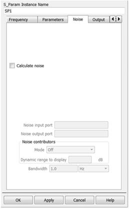
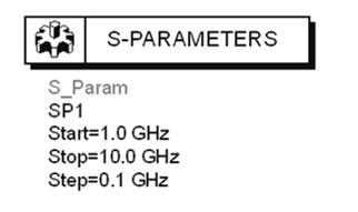
6 S-Parameter Simulation 2015 Page 11 S-Parameter Termination Termination can be any impedance value Port Count is not limited No Calibration needed 2015 Page 12 6
7 S-Parameter Simulation (Frequency-domain) DC analysis is performed to find the bias point Nonlinear devices linearized at the bias point Assumes signal does not perturb the bias S-parameter sources are ports Components characterized by I and their small-signal [S] or [Y] Finds solution such that sum of all AC currents into each circuit node is zero (not iterative) Computes [S] and [Y] of the overall circuit at external ports Calculates response to small sinusoidal signals 2015 Page 13 S-Parameter Simulation 2015 Page 14 7
8 Instead of Take a Measurement We Run a Simulation 2015 Page 15 ADS Netlist 2015 Page 16 8

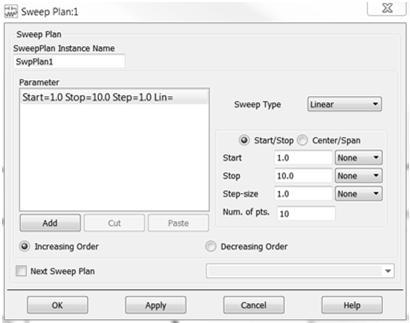

9 S-Parameter Controller Options/Sweep Plans 2015 Page 17 S-Parameter Controller Options/Sweep Plans 2015 Page 18 9


10 Tune 2015 Page 19 Transmission Lines 2015 Page 20 10
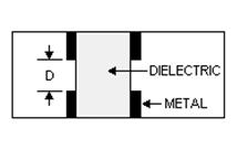
11 Ideal Transmission Line 2015 Page 21 Microstrip Transmission Lines Surface Roughness Option Frequency Dependent Dielectric Model 2015 Page 22 11

12 Multilayer Transmission Lines 2015 Page 23 Integration of EM Solvers Method of Moments Finite Elements Method 2015 Page 24 12
13 Power Transfer Efficiency RS RL For complex impedances, maximum power transfer occurs when Z L = Z S * (conjugate match) Load Power (normalized) RL / RS Maximum power is transferred when R L = R S 2015 Page 25 Power Transfer Efficiency 2015 Page 26 13
14 AC Analysis (Frequency-domain simulator) DC Analysis is performed to find the bias point Nonlinear devices linearized at the bias point Assumes signal does not perturb the bias Sources are voltage and current sine waves Superposition is allowed and encouraged Outputs are voltage and current Sums all AC currents into each circuit node (not iterative) 2015 Page 27 Power Transfer Efficiency 2015 Page 28 14
15 Power Transfer Efficiency 2015 Page 29 Power Transfer Efficiency 2015 Page 30 15
 Z L =")
16 Smith Chart Review +jx Polar plane 90 o R o o 0 -jx Rectilinear impedance plane Smith Chart maps rectilinear impedance plane onto polar plane Z = 0 L Γ Z L= Zo Γ = 0 = 1 ±180 O Inductive -90 o (short) Z L = Constant X Γ Constant R = 1 0 O (open) Capacitive Smith Chart 2015 Page 31 Series Capacitance 2015 Page 32 16

17 Series Inductance 2015 Page 33 Series Resonance 2015 Page 34 17


18 Separating Resonant Elements 2015 Page 35 Example of Matching Elements 2015 Page 36 18
19 Example of Matching Elements 2015 Page 37 Smith Chart Characteristics 2015 Page 38 19


20 Modeling Linear Behavior In ADS S-Parameters 2015 Page 39 Using Optimization to Develop Models 2015 Page 40 20

21 AmodelB Optimization Setup 2015 Page 41 S-Parameters Before and After Optimization Before Optimization After Optimization 2015 Page 42 21

22 SP_Probe 2015 Page 43 Starting LineCalc 2015 Page 44 22
 The solution, in the case of a complex circuit, will consist of a system of nonlinear equations which is solved using the Newton- Raphson method")
23 LineCalc Tool 2015 Page 45 Transient Analysis Just like SPICE Kirchoff s current equations are derived at each node in differential form v(t) The time derivatives are replaced with discrete-time approximations (integration) The solution, in the case of a complex circuit, will consist of a system of nonlinear equations which is solved using the Newton- Raphson method 2015 Page 46 23
24 Convolution Analysis Convolution calculates the response of distributed and dispersive network, to an arbitrary transient time-domain waveform. Models can includes conductor loss, dielectric loss, self-and coupled inductance and capacitance, as functions of frequency, and multi-port s-parameter data sets from measurements and field solvers. Impulse response for all distributed components is calculated, then convolved with input signal to yield output Results can be transformed to the frequency domain Page 47 Transient Simulation with Convolution 2015 Page 48 24
25 Harmonic Balance (Steady State Analysis) Start Simulation Frequencies Number of Harmonics Number of Mixing Products DC analysis always done Linear Components Measure Linear Circuit Currents in the Frequency-Domain Nonlinear Components Measure Nonlinear Circuit Voltages in the Frequency-Domain Inverse Fourier Transform: Nonlinear Voltage Now in the Time Domain Calculate Nonlinear Currents Fourier Transform: Nonlinear Currents Now back in the Frequency Domain Test: Error > Tolerance: if yes, modify & recalculate if no, then Stop= correct answer Page 49 Example Circuit: First and Last Iterations IR IC IL ID IY-port (Momentum file) Start in the Frequency Domain Calculate currents Convert: ts -> fs Initial Estimate: spectral voltage IR IC IL ID IY If within tolerance Last Estimate with least error IR IC IL ID I Y the n V Final Solution 2015 Page 50 25


26 Harmonic Balance Setup 2015 Page 51 Harmonic Balance Results 2015 Page 52 26
 Compute")


27 Modulated Sources 2015 Page 53 Circuit Envelope Time samples the modulation envelope (not carrier) Compute the spectrum at each time sample Output a time-varying spectrum Use equations on the data Faster than HB or Spice in many cases Integrates with System Simulations & Keysight s Ptolemy Next, what tests can it perform? 2015 Page 54 27
28 Test Circuits with Realistic Signals GSM, CDMA, GMSK, pi/4dqpsk, QPSK, etc. Simulations can include: Example CE results: 32.8 khz BW for NADC Adjacent Channel Power Ratio Noise Power Ratio Error Vector Magnitude Power Added Efficiency Bit Error Rate 2-tone tests and linearized models do not predict this behavior as easily! Also, Envelope can be used for PLL simulations: lock time, spurious signals, modulation in the loop. 890 MHz carrier 2015 Page 55 Circuit Envelope Technology Circuit V(t) * e t 3 Modulation t 2 t 4 t 1 j2π fot Vout Carrier Time sample the envelope and then perform Harmonic Balance on the samples! More... Periodic input signal NOTE: V(t) can be complex - am or fm or pm 2015 Page 56 28
29 More on CE Technology Captures time and frequency characteristics: Next, an example... dbm (fs (Vout[1])) 2015 Page 57 IS-95 Forward Link Modulated Signal Generation 2015 Page 58 29


30 IS-95 Forward Link Modulated Signal Generation 2015 Page 59 What are X-Parameters? X-parameters are the mathematically correct superset of S- parameters, applicable to both large-signal and small-signal conditions, for linear and nonlinear components. The math exists! We can measure, model, & simulate with X-parameters Each part of the puzzle has been created The pieces now fit together seamlessly NVNA: Measure X-parameters PHD: X-parameter block ADS: Simulate X-parameters Interoperable Nonlinear Measurement, Modeling & Simulation with X-parameters X-parameters have the potential to do for characterization, modeling, and design of nonlinear components and systems what linear S-parameters do for linear components & systems 2015 Page 60 30

31 X-parameters From Poly-Harmonic Distortion (PHD) 2015 Page 61 Experiment Setup and Simulation Schematic Objective: Design nonlinear circuits in ADS from NVNA-measured X-parameters of individual components 2015 Page 62 31


32 Cascaded Simulation vs. Measurement Red: Cascade Measurement Blue: Simulation of Cascaded Models X-parameters enable predictive nonlinear design from NL data 2015 Page 63 Thank you! For More Information ADS on Evaluate ADS Page 64 32
Advanced Design System - Fundamentals. Mao Wenjie
 Advanced Design System - Fundamentals Mao Wenjie wjmao@263.net Main Topics in This Class Topic 1: ADS and Circuit Simulation Introduction Topic 2: DC and AC Simulations Topic 3: S-parameter Simulation
Appendix. Harmonic Balance Simulator. Page 1
 Appendix Harmonic Balance Simulator Page 1 Harmonic Balance for Large Signal AC and S-parameter Simulation Harmonic Balance is a frequency domain analysis technique for simulating distortion in nonlinear
Ansys Designer RF Training Lecture 3: Nexxim Circuit Analysis for RF
 Ansys Designer RF Solutions for RF/Microwave Component and System Design 7. 0 Release Ansys Designer RF Training Lecture 3: Nexxim Circuit Analysis for RF Designer Overview Ansoft Designer Advanced Design
Appendix. RF Transient Simulator. Page 1
 Appendix RF Transient Simulator Page 1 RF Transient/Convolution Simulation This simulator can be used to solve problems associated with circuit simulation, when the signal and waveforms involved are modulated
Final Circuit & System Simulation - with Optional
 Final Circuit & System Simulation - with Optional Co-Simulation Slide 9-1 What is the final topic in this class? Simulation of your amp_1900 and filters in the receiver system to verify analog performance.
Network Analysis Basics
 Adolfo Del Solar Application Engineer adolfo_del-solar@agilent.com MD1010 Network B2B Agenda Overview What Measurements do we make? Network Analyzer Hardware Error Models and Calibration Example Measurements
Direct-Conversion I-Q Modulator Simulation by Andy Howard, Applications Engineer Agilent EEsof EDA
 Direct-Conversion I-Q Modulator Simulation by Andy Howard, Applications Engineer Agilent EEsof EDA Introduction This article covers an Agilent EEsof ADS example that shows the simulation of a directconversion,
Agilent Technologies Gli analizzatori di reti della serie-x
 Agilent Technologies Gli analizzatori di reti della serie-x Luigi Fratini 1 Introducing the PNA-X Performance Network Analyzer For Active Device Test 500 GHz & beyond! 325 GHz 110 GHz 67 GHz 50 GHz 43.5
EM Analysis of RFIC Transmission Lines
 EM Analysis of RFIC Transmission Lines Purpose of this document: In this document, we will discuss the analysis of single ended and differential on-chip transmission lines, the interpretation of results
System Design Fundamentals
 System Design Fundamentals Slide 2-1 BEFORE starting with system design...some details on the ADS Main window: Main Window: File or Project View VS Right Click More on Main... Slide 2-2 BEFORE starting
Keysight Technologies Nonlinear Vector Network Analyzer (NVNA) Breakthrough technology for nonlinear vector network analysis from 10 MHz to 67 GHz
 Breakthrough technology for nonlinear vector network analysis from 10 MHz to 67 GHz") Keysight Technologies Nonlinear Vector Network Analyzer (NVNA) Breakthrough technology for nonlinear vector network analysis from 1 MHz to 67 GHz 2 Keysight Nonlinear Vector Network Analyzer (NVNA) - Brochure
Keysight Technologies Nonlinear Vector Network Analyzer (NVNA) Breakthrough technology for nonlinear vector network analysis from 1 MHz to 67 GHz 2 Keysight Nonlinear Vector Network Analyzer (NVNA) - Brochure
Efficiently simulating a direct-conversion I-Q modulator
 Efficiently simulating a direct-conversion I-Q modulator Andy Howard Applications Engineer Agilent Eesof EDA Overview An I-Q or vector modulator is a commonly used integrated circuit in communication systems.
Linear networks analysis
 Linear networks analysis For microwave linear networks analysis is performed in frequency domain. The analysis is based on the evaluation of the scattering matrix of the n port network From S matrix all
Signals and Systems Lecture 9 Communication Systems Frequency-Division Multiplexing and Frequency Modulation (FM)
") Signals and Systems Lecture 9 Communication Systems Frequency-Division Multiplexing and Frequency Modulation (FM) April 11, 2008 Today s Topics 1. Frequency-division multiplexing 2. Frequency modulation
Signals and Systems Lecture 9 Communication Systems Frequency-Division Multiplexing and Frequency Modulation (FM) April 11, 2008 Today s Topics 1. Frequency-division multiplexing 2. Frequency modulation
Evaluation of Package Properties for RF BJTs
 Application Note Evaluation of Package Properties for RF BJTs Overview EDA simulation software streamlines the development of digital and analog circuits from definition of concept and estimation of required
Understanding the Fundamental Principles of Vector Network Analysis. Application Note
 Understanding the Fundamental Principles of Vector Network Analysis Application Note Table of Contents Introduction... 3 Measurements in Communications Systems... 3 Importance of Vector Measurements...
Measurements with Scattering Parameter By Joseph L. Cahak Copyright 2013 Sunshine Design Engineering Services
 Measurements with Scattering Parameter By Joseph L. Cahak Copyright 2013 Sunshine Design Engineering Services Network Analyzer Measurements In many RF and Microwave measurements the S-Parameters are typically
Introduction to RF Simulation and Its Applications
 Introduction to RF Simulation and Its Applications by Kenneth S. Kundert Presenter - Saurabh Jain What will he talk about? Challenges for RF design and simulations RF circuit characteristics Basic RF building
The wireless industry
 From May 2007 High Frequency Electronics Copyright Summit Technical Media, LLC RF SiP Design Verification Flow with Quadruple LO Down Converter SiP By HeeSoo Lee and Dean Nicholson Agilent Technologies
Lecture 8. Jaeha Kim. Seoul National University
 Lecture 8. Introduction to RF Simulation Jaeha Kim Mixed-Signal IC and System Group (MICS) Seoul National University jaeha@ieee.org 1 Overview Readings: K. Kundert, Introduction to RF Simulation and Its
SmartSpice RF Harmonic Balance Based and Shooting Method Based RF Simulation
 SmartSpice RF Harmonic Balance Based and Shooting Method Based RF Simulation Silvaco Overview SSRF Attributes Harmonic balance approach to solve system of equations in frequency domain Well suited for
Microwave Oscillator Design. Application Note A008
 Microwave Oscillator Design Application Note A008 NOTE: This publication is a reprint of a previously published Application Note and is for technical reference only. For more current information, see the
GSM Transmitter Modulation Quality Measurement Option
 Performs all required measurements for GSM transmitters Outputs multiple time mask parameters for process control analysis Obtains frequency error, rms phase error, and peak phase error with one command
Department of Electronics &Electrical Engineering
 Department of Electronics &Electrical Engineering Question Bank- 3rd Semester, (Network Analysis & Synthesis) EE-201 Electronics & Communication Engineering TWO MARKS OUSTIONS: 1. Differentiate between
MEASUREMENT OF LARGE SIGNAL DEVICE INPUT IMPEDANCE DURING LOAD PULL
 Model M956D CORPORAION MEASUREMEN OF LARGE SIGNAL DEVICE INPU IMPEDANCE DURING LOAD PULL Abstract Knowledge of device input impedance as a function of power level and load matching is useful to fully understand
Application Note A008
 Microwave Oscillator Design Application Note A008 Introduction This application note describes a method of designing oscillators using small signal S-parameters. The background theory is first developed
Agilent EEsof EDA.
 Agilent EEsof EDA This document is owned by Agilent Technologies, but is no longer kept current and may contain obsolete or inaccurate references. We regret any inconvenience this may cause. For the latest
System analysis and signal processing
 System analysis and signal processing with emphasis on the use of MATLAB PHILIP DENBIGH University of Sussex ADDISON-WESLEY Harlow, England Reading, Massachusetts Menlow Park, California New York Don Mills,
Pulsed VNA Measurements:
 Pulsed VNA Measurements: The Need to Null! January 21, 2004 presented by: Loren Betts Copyright 2004 Agilent Technologies, Inc. Agenda Pulsed RF Devices Pulsed Signal Domains VNA Spectral Nulling Measurement
SmartSpice RF Harmonic Balance Based RF Simulator. Advanced RF Circuit Simulation
 SmartSpice RF Harmonic Balance Based RF Simulator Advanced RF Circuit Simulation SmartSpice RF Overview Uses harmonic balance approach to solve system equations in frequency domain Well suited for RF and
RF, Microwave & Wireless. All rights reserved
 RF, Microwave & Wireless All rights reserved 1 Non-Linearity Phenomenon All rights reserved 2 Physical causes of nonlinearity Operation under finite power-supply voltages Essential non-linear characteristics
A Simplified Extension of X-parameters to Describe Memory Effects for Wideband Modulated Signals
 Jan Verspecht bvba Mechelstraat 17 B-1745 Opwijk Belgium email: contact@janverspecht.com web: http://www.janverspecht.com A Simplified Extension of X-parameters to Describe Memory Effects for Wideband
f o Fig ECE 6440 Frequency Synthesizers P.E. Allen Frequency Magnitude Spectral impurity Frequency Fig010-03
 Lecture 010 Introduction to Synthesizers (5/5/03) Page 010-1 LECTURE 010 INTRODUCTION TO FREQUENCY SYNTHESIZERS (References: [1,5,9,10]) What is a Synthesizer? A frequency synthesizer is the means by which
SC5407A/SC5408A 100 khz to 6 GHz RF Upconverter. Datasheet. Rev SignalCore, Inc.
 SC5407A/SC5408A 100 khz to 6 GHz RF Upconverter Datasheet Rev 1.2 2017 SignalCore, Inc. support@signalcore.com P R O D U C T S P E C I F I C A T I O N S Definition of Terms The following terms are used
Extension of X-parameters to Include Long-Term Dynamic Memory Effects
 Jan Verspecht bvba Mechelstraat 17 B-1745 Opwijk Belgium email: contact@janverspecht.com web: http://www.janverspecht.com Extension of X-parameters to Include Long-Term Dynamic Memory Effects Jan Verspecht,
Innovations in EDA Webcast Series
 Welcome Innovations in EDA Webcast Series August 2, 2012 Jack Sifri MMIC Design Flow Specialist IC, Laminate, Package Multi-Technology PA Module Design Methodology Realizing the Multi-Technology Vision
Lab 4. Crystal Oscillator
 Lab 4. Crystal Oscillator Modeling the Piezo Electric Quartz Crystal Most oscillators employed for RF and microwave applications use a resonator to set the frequency of oscillation. It is desirable to
MT1000 and MT2000 Mixed-Signal Active Load Pull System (1.0 MHz to 40.0 GHz) And MT2001 System Software
 And MT2001 System Software") MT1000 and MT0 Mixed-Signal Active Load Pull System (1.0 MHz to 40.0 GHz) And MT1 System Software DATA SHEET / 4T-097 U.S. Patent No. 8,456,175 B2 Several international patents also available // SEPTEMBER
MT1000 and MT0 Mixed-Signal Active Load Pull System (1.0 MHz to 40.0 GHz) And MT1 System Software DATA SHEET / 4T-097 U.S. Patent No. 8,456,175 B2 Several international patents also available // SEPTEMBER
RF Board Design for Next Generation Wireless Systems
 RF Board Design for Next Generation Wireless Systems Page 1 Introduction Purpose: Provide basic background on emerging WiMax standard Introduce a new tool for Genesys that will aide in the design and verification
915 MHz Power Amplifier. EE172 Final Project. Michael Bella
 915 MHz Power Amplifier EE17 Final Project Michael Bella Spring 011 Introduction: Radio Frequency Power amplifiers are used in a wide range of applications, and are an integral part of many daily tasks.
RF/IF Terminology and Specs
 RF/IF Terminology and Specs Contributors: Brad Brannon John Greichen Leo McHugh Eamon Nash Eberhard Brunner 1 Terminology LNA - Low-Noise Amplifier. A specialized amplifier to boost the very small received
Impedance 50 (75 connectors via adapters)
") VECTOR NETWORK ANALYZER PLANAR 304/1 DATA SHEET Frequency range: 300 khz to 3.2 GHz Measured parameters: S11, S21, S12, S22 Dynamic range of transmission measurement magnitude: 135 db Measurement time
VECTOR NETWORK ANALYZER PLANAR 304/1 DATA SHEET Frequency range: 300 khz to 3.2 GHz Measured parameters: S11, S21, S12, S22 Dynamic range of transmission measurement magnitude: 135 db Measurement time
Calibration technique for calibrating high speed equivalent time sampling scope using a characterized high speed photo diode
 Calibration technique for calibrating high speed equivalent time sampling scope using a characterized high speed photo diode Motivation PNA-X Non-linear network analyzer application Measurement technique
AC Analyses. Chapter Introduction
 Chapter 3 AC Analyses 3.1 Introduction The AC analyses are a family of frequency-domain analyses that include AC analysis, transfer function (XF) analysis, scattering parameter (SP, TDR) analyses, and
Harmonic Balance Simulation
 Harmonic Balance Simulation September 2004 Notice The information contained in this document is subject to change without notice. Agilent Technologies makes no warranty of any kind with regard to this
HP Archive. This vintage Hewlett Packard document was preserved and distributed by www. hparchive.com Please visit us on the web!
 HP Archive This vintage Hewlett Packard document was preserved and distributed by www. hparchive.com Please visit us on the web! On-line curator: Glenn Robb This document is for FREE distribution only!
AWR. White Paper. Nonlinear Modeling AWR S SUPPORT OF POLYHARMONIC DISTORTION AND NONLINEAR BEHAVIORAL MODELS
 AWR S SUPPORT OF POLYHARMONIC DISTORTION AND NONLINEAR BEHAVIORAL MODELS Linear and nonlinear device models are the building blocks of most RF and microwave designs. S-parameters are often used to represent
Microwave and RF Engineering
 Microwave and RF Engineering A Simulation Approach with Keysight Genesys Software Chapter 4: Resonant Circuits and Filters Ali A. Behagi Stephen D. Turner Microwave and RF Engineering A Simulation Approach
Validation & Analysis of Complex Serial Bus Link Models
 Validation & Analysis of Complex Serial Bus Link Models Version 1.0 John Pickerd, Tektronix, Inc John.J.Pickerd@Tek.com 503-627-5122 Kan Tan, Tektronix, Inc Kan.Tan@Tektronix.com 503-627-2049 Abstract
Analysis and Design of Autonomous Microwave Circuits
 Analysis and Design of Autonomous Microwave Circuits ALMUDENA SUAREZ IEEE PRESS WILEY A JOHN WILEY & SONS, INC., PUBLICATION Contents Preface xiii 1 Oscillator Dynamics 1 1.1 Introduction 1 1.2 Operational
SC5307A/SC5308A 100 khz to 6 GHz RF Downconverter. Datasheet SignalCore, Inc.
 SC5307A/SC5308A 100 khz to 6 GHz RF Downconverter Datasheet 2017 SignalCore, Inc. support@signalcore.com P RODUCT S PECIFICATIONS Definition of Terms The following terms are used throughout this datasheet
Keysight Technologies RF and Microwave Industry-Ready Student Certification Program
 Keysight Technologies RF and Microwave Industry-Ready Student Certification Program The Keysight RF and Microwave Industry-Ready Student Certification Program confirms the student s technical knowledge,
Glossary of VCO terms
 Glossary of VCO terms VOLTAGE CONTROLLED OSCILLATOR (VCO): This is an oscillator designed so the output frequency can be changed by applying a voltage to its control port or tuning port. FREQUENCY TUNING
Agilent EEsof EDA. Enabling First Pass Success. Chee Keong, Teo Business Development Manager EEsof South Asia. Agilent Restricted
 Agilent EEsof EDA Enabling First Pass Success Chee Keong, Teo Business Development Manager EEsof South Asia EEsof EDA is Strategic to Agilent Technologies As the world s premier measurement company, Agilent
Examining The Concept Of Ground In Electromagnetic (EM) Simulation
 Simulation") Examining The Concept Of Ground In Electromagnetic (EM) Simulation While circuit simulators require a global ground, EM simulators don t concern themselves with ground at all. As a result, it is the designer
Examining The Concept Of Ground In Electromagnetic (EM) Simulation While circuit simulators require a global ground, EM simulators don t concern themselves with ground at all. As a result, it is the designer
Using X-Parameters* to Generate IBIS Models
 Using X-Parameters* to Generate IBIS Models Tom Comberiate and José Schutt-Ainé University of Illinois at Urbana-Champaign tcomber2@illinois.edu IBIS Summit at DesignCon January 31, 2013 Santa Clara, CA
Application Note SAW-Components
 Application Note SAW-Components Comparison between negative impedance oscillator (Colpitz oscillator) and feedback oscillator (Pierce structure) App.: Note #13 Author: Alexander Glas EPCOS AG Updated:
Keysight Technologies Understanding the SystemVue To ADS Simulation Bridge. Application Note
 Keysight Technologies Understanding the To Simulation Bridge Application Note Introduction The Keysight Technologies, Inc. is a new system-level design environment that enables a top-down, model-based
Lecture 6. Angle Modulation and Demodulation
 Lecture 6 and Demodulation Agenda Introduction to and Demodulation Frequency and Phase Modulation Angle Demodulation FM Applications Introduction The other two parameters (frequency and phase) of the carrier
Evaluating and Optimizing Tradeoffs in CMOS RFIC Upconversion Mixer Design. by Dr. Stephen Long University of California, Santa Barbara
 Evaluating and Optimizing Tradeoffs in CMOS RFIC Upconversion Mixer Design by Dr. Stephen Long University of California, Santa Barbara It is not easy to design an RFIC mixer. Different, sometimes conflicting,
Modulation is the process of impressing a low-frequency information signal (baseband signal) onto a higher frequency carrier signal
 onto a higher frequency carrier signal") Modulation is the process of impressing a low-frequency information signal (baseband signal) onto a higher frequency carrier signal Modulation is a process of mixing a signal with a sinusoid to produce
Modulation is the process of impressing a low-frequency information signal (baseband signal) onto a higher frequency carrier signal Modulation is a process of mixing a signal with a sinusoid to produce
VSWR MEASUREMENT APPLICATION NOTE ANV004.
 APPLICATION NOTE ANV004 Bötelkamp 31, D-22529 Hamburg, GERMANY Phone: +49-40 547 544 60 Fax: +49-40 547 544 666 Email: info@valvo.com Introduction: VSWR stands for voltage standing wave ratio. The ratio
SHF Communication Technologies AG
 SHF Communication Technologies AG Wilhelm-von-Siemens-Str. 23 Aufgang D 2277 Berlin Marienfelde Germany Phone ++49 30 / 772 05 0 Fax ++49 30 / 753 0 78 E-Mail: sales@shf.biz Web: http://www.shf.biz Tutorial
When Should You Apply 3D Planar EM Simulation?
 When Should You Apply 3D Planar EM Simulation? Agilent EEsof EDA IMS 2010 MicroApps Andy Howard Agilent Technologies 1 3D planar EM is now much more of a design tool Solves bigger problems and runs faster
Analysis of Microstrip Circuits Using a Finite-Difference Time-Domain Method
 Analysis of Microstrip Circuits Using a Finite-Difference Time-Domain Method M.G. BANCIU and R. RAMER School of Electrical Engineering and Telecommunications University of New South Wales Sydney 5 NSW
Signals A Preliminary Discussion EE442 Analog & Digital Communication Systems Lecture 2
 Signals A Preliminary Discussion EE442 Analog & Digital Communication Systems Lecture 2 The Fourier transform of single pulse is the sinc function. EE 442 Signal Preliminaries 1 Communication Systems and
Scattered thoughts on Scattering Parameters By Joseph L. Cahak Copyright 2013 Sunshine Design Engineering Services
 Scattered thoughts on Scattering Parameters By Joseph L. Cahak Copyright 2013 Sunshine Design Engineering Services Scattering parameters or S-parameters (aka Spars) are used by RF and microwave engineers
ELEN 701 RF & Microwave Systems Engineering. Lecture 8 November 8, 2006 Dr. Michael Thorburn Santa Clara University
 ELEN 701 RF & Microwave Systems Engineering Lecture 8 November 8, 2006 Dr. Michael Thorburn Santa Clara University System Noise Figure Signal S1 Noise N1 GAIN = G Signal G x S1 Noise G x (N1+No) Self Noise
Multilayer VIA simulations using ADS Anurag Bhargava, Application Consultant, Agilent EEsof EDA, Agilent Technologies
 Multilayer VIA simulations using ADS Anurag Bhargava, Application Consultant, Agilent EEsof EDA, Agilent Technologies Many a time designers find themselves in pretty confusing start when it comes to simulating
A Simplified Extension of X-parameters to Describe Memory Effects for Wideband Modulated Signals
 A Simplified Extension of X-parameters to Describe Memory Effects for Wideband Modulated Signals Jan Verspecht*, Jason Horn** and David E. Root** * Jan Verspecht b.v.b.a., Opwijk, Vlaams-Brabant, B-745,
New Ultra-Fast Noise Parameter System... Opening A New Realm of Possibilities in Noise Characterization
 New Ultra-Fast Noise Parameter System... Opening A New Realm of Possibilities in Noise Characterization David Ballo Application Development Engineer Agilent Technologies Gary Simpson Chief Technology Officer
Agilent ENA Series 2, 3 and 4 Port RF Network Analyzers
 gilent EN Series 2, 3 and 4 Port RF Network nalyzers 蔡明汎 gilent EO Project Manager (07)3377603 Email:ming-fan_tsai@agilent.com OTS:0800-047866 EN 1 genda What measurements do we make? Network nalyzer Hardware
Simulation of Radio Frequency Integrated Circuits
 Simulation o Radio Frequency Integrated Circuits Based on: Computer-Aided Circuit Analysis Tools or RFIC Simulation: Algorithms, Features, and Limitations, IEEE Trans. CAS-II, April 2000. Outline Introduction
2.2 INTERCONNECTS AND TRANSMISSION LINE MODELS
 CHAPTER 2 MODELING OF SELF-HEATING IN IC INTERCONNECTS AND INVESTIGATION ON THE IMPACT ON INTERMODULATION DISTORTION 2.1 CONCEPT OF SELF-HEATING As the frequency of operation increases, especially in the
Chapter 1 - Antennas
 EE 483/583/L Antennas for Wireless Communications 1 / 8 1.1 Introduction Chapter 1 - Antennas Definition - That part of a transmitting or receiving system that is designed to radiate or to receive electromagnetic
EE42: Running Checklist of Electronics Terms Dick White
 EE42: Running Checklist of Electronics Terms 14.02.05 Dick White Terms are listed roughly in order of their introduction. Most definitions can be found in your text. Terms2 TERM Charge, current, voltage,
This novel simulation method effectively analyzes a 2-GHz oscillator to better understand and optimize its noise performance.
 1 of 8 12/29/2015 12:53 PM print close Microwaves and RF Mark Scott Logue Tue, 2015-12-29 12:19 This novel simulation method effectively analyzes a 2-GHz oscillator to better understand and optimize its
i. At the start-up of oscillation there is an excess negative resistance (-R)
") OSCILLATORS Andrew Dearn * Introduction The designers of monolithic or integrated oscillators usually have the available process dictated to them by overall system requirements such as frequency of operation
OSCILLATORS Andrew Dearn * Introduction The designers of monolithic or integrated oscillators usually have the available process dictated to them by overall system requirements such as frequency of operation
AWR. SIP Flow White Paper UNDERSTANDING AVAILABLE TOOLS FOR RF SYSTEM-IN-PACKAGE AND MULTI-CHIP-MODULE DESIGN AND OPTIMIZATION
 UNDERSTANDING AVAILABLE TOOLS FOR RF SYSTEM-IN-PACKAGE AND MULTI-CHIP-MODULE DESIGN AND OPTIMIZATION RF system-in-package (SiP) and multi-chip-module (MCM) designs present engineers with the challenge
Keywords: rf, rfic, wireless, cellular, cdma, if, oscillator, rfics, IF frequencies, VCO, rf ic
 Maxim > Design Support > Technical Documents > Application Notes > Wireless and RF > APP 272 Keywords: rf, rfic, wireless, cellular, cdma, if, oscillator, rfics, IF frequencies, VCO, rf ic APPLICATION
Schematic-Level Transmission Line Models for the Pyramid Probe
 Schematic-Level Transmission Line Models for the Pyramid Probe Abstract Cascade Microtech s Pyramid Probe enables customers to perform production-grade, on-die, full-speed test of RF circuits for Known-Good
EMDS for ADS Momentum
 EMDS for ADS Momentum ADS User Group Meeting 2009, Böblingen, Germany Prof. Dr.-Ing. Frank Gustrau Gustrau, Dortmund User Group Meeting 2009-1 Univ. of Applied Sciences and Arts (FH Dortmund) Presentation
UNIT 1 CIRCUIT ANALYSIS 1 What is a graph of a network? When all the elements in a network is replaced by lines with circles or dots at both ends.
 UNIT 1 CIRCUIT ANALYSIS 1 What is a graph of a network? When all the elements in a network is replaced by lines with circles or dots at both ends. 2 What is tree of a network? It is an interconnected open
ELECTRIC CIRCUITS. Third Edition JOSEPH EDMINISTER MAHMOOD NAHVI
 ELECTRIC CIRCUITS Third Edition JOSEPH EDMINISTER MAHMOOD NAHVI Includes 364 solved problems --fully explained Complete coverage of the fundamental, core concepts of electric circuits All-new chapters
Prediction of Co-site interference in complex RF environments
 Prediction of Co-site interference in complex RF environments Frank Demming-Janssen CST AG The Cosite Scenario Multiple RF systems co-located in a common environment Diverse system characteristics Frequency
SECTION 7: FREQUENCY DOMAIN ANALYSIS. MAE 3401 Modeling and Simulation
 SECTION 7: FREQUENCY DOMAIN ANALYSIS MAE 3401 Modeling and Simulation 2 Response to Sinusoidal Inputs Frequency Domain Analysis Introduction 3 We ve looked at system impulse and step responses Also interested
Synthesis of Optimal On-Chip Baluns
 Synthesis of Optimal On-Chip Baluns Sharad Kapur, David E. Long and Robert C. Frye Integrand Software, Inc. Berkeley Heights, New Jersey Yu-Chia Chen, Ming-Hsiang Cho, Huai-Wen Chang, Jun-Hong Ou and Bigchoug
EE228 Applications of Course Concepts. DePiero
 EE228 Applications of Course Concepts DePiero Purpose Describe applications of concepts in EE228. Applications may help students recall and synthesize concepts. Also discuss: Some advanced concepts Highlight
VCO Design Project ECE218B Winter 2011
 VCO Design Project ECE218B Winter 2011 Report due 2/18/2011 VCO DESIGN GOALS. Design, build, and test a voltage-controlled oscillator (VCO). 1. Design VCO for highest center frequency (< 400 MHz). 2. At
Design and Matching of a 60-GHz Printed Antenna
 Application Example Design and Matching of a 60-GHz Printed Antenna Using NI AWR Software and AWR Connected for Optenni Figure 1: Patch antenna performance. Impedance matching of high-frequency components
Lecture 17: BJT/FET Mixers/Mixer Noise
 EECS 142 Lecture 17: BJT/FET Mixers/Mixer Noise Prof. Ali M. Niknejad University of California, Berkeley Copyright c 2005 by Ali M. Niknejad A. M. Niknejad University of California, Berkeley EECS 142 Lecture
Lab 4: Transmission Line
 1 Introduction Lab 4: Transmission Line In this experiment we will study the properties of a wave propagating in a periodic medium. Usually this takes the form of an array of masses and springs of the
Outline. Communications Engineering 1
 Outline Introduction Signal, random variable, random process and spectra Analog modulation Analog to digital conversion Digital transmission through baseband channels Signal space representation Optimal
Custom Interconnects Fuzz Button with Hardhat Test Socket/Interposer 1.00 mm pitch
 Custom Interconnects Fuzz Button with Hardhat Test Socket/Interposer 1.00 mm pitch Measurement and Model Results prepared by Gert Hohenwarter 12/14/2015 1 Table of Contents TABLE OF CONTENTS...2 OBJECTIVE...
How to Utilize a Windowing Technique for Accurate DFT
 How to Utilize a Windowing Technique for Accurate DFT Product Version IC 6.1.5 and MMSIM 12.1 December 6, 2013 By Michael Womac Copyright Statement 2013 Cadence Design Systems, Inc. All rights reserved
Reflectometer Series:
 Reflectometer Series: R54, R60 & R140 Vector Network Analyzers Clarke & Severn Electronics Ph +612 9482 1944 Email sales@clarke.com.au BUY NOW - www.cseonline.com.au KEY FEATURES Patent: US 9,291,657 No
RF and Microwave Test and Design Roadshow 5 Locations across Australia and New Zealand
 RF and Microwave Test and Design Roadshow 5 Locations across Australia and New Zealand Advanced VNA Measurements Agenda Overview of the PXIe-5632 Architecture SW Experience Overview of VNA Calibration
Large-Signal Measurements Going beyond S-parameters
 Large-Signal Measurements Going beyond S-parameters Jan Verspecht, Frans Verbeyst & Marc Vanden Bossche Network Measurement and Description Group Innovating the HP Way Overview What is Large-Signal Network
Welcome. Steven Baker Founder & Director OpenET Alliance. Andy Howard Senior Application Specialist Agilent EEsof EDA Agilent Technologies, Inc.
 Welcome Steven Baker Founder & Director OpenET Alliance Andy Howard Senior Application Specialist Agilent EEsof EDA 1 Outline Steven Baker, OpenET Alliance What problem are we trying to solve? What is
UNIT 2. Q.1) Describe the functioning of standard signal generator. Ans. Electronic Measurements & Instrumentation
 Describe the functioning of standard signal generator. Ans. Electronic Measurements & Instrumentation") UNIT 2 Q.1) Describe the functioning of standard signal generator Ans. STANDARD SIGNAL GENERATOR A standard signal generator produces known and controllable voltages. It is used as power source for the
UNIT 2 Q.1) Describe the functioning of standard signal generator Ans. STANDARD SIGNAL GENERATOR A standard signal generator produces known and controllable voltages. It is used as power source for the