MMIC/RFIC Packaging Challenges Webcast (July 28, AM PST 12PM EST)
|
|
|
- Joy Benson
- 5 years ago
- Views:
Transcription

1 MMIC/RFIC Packaging Challenges Webcast ( 9AM PST 12PM EST) Board Package Chip HEESOO LEE Agilent EEsof 3DEM Technical Lead 1
2 Agenda 1. MMIC/RFIC packaging challenges 2. Design techniques and solutions that improve package performance 3. The value of chip/package co-design Case study: RFIC differential power amplifier 4. Conclusion 2


3 What Applications We Will Cover Agilent Custom TOPS Package Agilent QFN Package Solder Bumps for FC Package Balun + Mixer IC Module RFIC PA Co-Design 3

4 1. MMIC/RFIC Packaging Challenges 4
5 MMIC/RFIC Packaging Trends Smaller, Cheaper, Faster Smaller form factor packages and higher integration Higher pin counts and smaller ball/pad pitch Embedded passives on module level multi-layer substrates Multi-technologies RF, MEMs, Logic, Analog, DRAM Lower cost and low power packages More wafer level packaging process Emerging 3DIC packaging technology Increasing thermal challenges Performance driven Form Cost factor driven driven Market drivers 5

6 Packaging Technologies and Modeling Approaches High Speed Digital Package Larger and complex Typically use time-domain simulations Spice models are generally required: Provide Intuitive physical meaning for package structures Tedious and time consuming process for model extraction where EM simulations are extensively used MMIC/RFIC Package Smaller and simpler Typically use frequency domain simulations Spice models are not always necessarily required but good to have them Possible to use EM models directly, which are multi-port S-parameters Broadband Spice Models can also alternatively be used but no intuitive physical meaning for the package 6
7 3D EM Simulation Technologies FDTD (Finite Difference Time Domain) FEM (Finite Element Method) MoM (Method of Moment) FDTD 3D arbitrary structures Full Wave EM simulations Handles much larger and complex problems Time Domain EM Simulate full size cell phone antennas EM simulations per each port GPU based hardware acceleration 3D Arbitrary Structures Full Wave EM Simulation Direct, Iterative Solvers Frequency Domain EM Multiport simulation at no additional cost High Q FEM MoM 3D Planar structures Full Wave and Quasi-Static Dense & Compressed Solvers Frequency Domain Multiport simulation at no additional cost High Q 7


8 Agilent EEsof s Integrated 3D EM Flow Package Designers EMPro Platform MMIC/RFIC Designers ADS Platform Parameterized 3D Components Layout CAD Data FDTD Simulator FEM Simulator Momentum Simulator 8


9 2. Design Techniques and Solutions that Improve Package Performance 9

 and non-hermetic molded LCP (Liquid Crystal")

10 Example 1: Agilent s High Performance Custom TOPS Package TOPS Package features: Micro-circuit performance up to 50 GHz and 40Gb/s with SMT Technology Excellent thermal (heat dissipation) capability Small form factor (10 mm x 10 mm) and non-hermetic molded LCP (Liquid Crystal Polymer) Low cost and high volume assembly/test with fast coax E-cal process BondWire MMIC BondWire Via RT4350 Top Side PC Board Cavity Metal Slug Bottom Side 10
 Excellent performance up to 50GHz -10 S11")

11 Measured Transition Performance of TOPS Package (PCB Package BondWire ThinFilm Load) Excellent performance up to 50GHz -10 S11 (db) Cal PCB data used to correct for PCB and connector losses Less than 20dB freq, GHz 11

12 Design Techniques Used to Improve TOPS Package Performance 1 Double wedge bonding for reducing effective inductance Bonding Features: 26 µm Diameter, 25µm bond height 2 Optimized bond pad size for low pass configuration 30 ff shunt capacitance with 200µm X 100 µm Circuit Model Term Term1 Num=1 Z=50 Ohm TLIN TL11 Z=50.0 Ohm E=47 F=40 GHz L L18 L=0.125 nh R= C C26 C= pf TLIN TL10 Z=50.0 Ohm E=47 C F=40 GHz C25 C= pf Term Term2 Num=2 Z=50 Ohm Bondwire Performance (Model vs.em) 3 Optimized via and pad size for reducing reflections Compensated25um db(s(1,1)) Comp25um_Phase phase(s(2,1)) High frequency PTFE for package substrate freq, GHz Return Loss freq, GHz Phase Response ff shunt capacitance with 200um X 100 um
13 Example 2: Agilent 3x3 [mm] 16 Pin QFN Package Top metal 0.1 mm thick Die Paddle Top View Plastic encasement 0.2 mm thick Bottom View Bottom metal 0.1 mm thick 13


14 Non-Optimized QFN Package Performance With 50Ohm Thru Line on Al Substrate Microstrip line on Al Substrate PCB vias from QFN to ground Bottom View Chip Top View Board Microstrip Feed Board Double bond wires Good Up to 15 GHz! 14

 1 Use split bond wires")
15 Design Techniques Used to Improve QFN Package Performance Increase the width of input/output transmission lines to 50 Ω impedance Easy to optimize in ADS Use two lead frames to maintain a good transitional impedance profile and split the double bondwires onto the two leads 2 Wider transmission line (50 Ω) 1 Use split bond wires onto two leads 15

16 Improved Package Performance db(s11) db(s21) Red & Blue: Improved Design Cyan & Dark Green: Original Design 16

17 3D Component Technology for 3D EM Simulations Bridges IC and package designers in 3D EM and circuit simulation space Augments ADS 2D layout drawing into 3D EM space for packages Two types of 3D components ADS default 3D components Custom Parameterized 3D components ADS Default 3D Components Custom Parameterized 3D Components EMPro Platform ADS Platform 17


18 Example 3: Solder/Wafer Bumps for Flip Chip Packaging Solder/Wafer Bumps are very typical interconnect technology for Flip-Chip, CSP, and WLP applications 3D full wave EM simulations are required to characterize it and analyze board interactions with face-down flip chip Silicon Die PCB Board Bumps 18


19 Solder Ball/Bump ADS Default 3D Component Greatly reduce the risk that comes with the final integration by co-designing the circuit, package, and board interface together. Use solder bumps from ADS default 3D component library, and get the most accurate prediction of the overall behavior Multiple E field plot 3D Component In ADS E-field plot 19
20 Simulated Isolation Performance between Bumps Less than 20 db Isolation Simulation Time: Only 5 min 25s on quad-core processor! 20


21 Build Custom Package 3D Component Library for ADS Circuit/EM Co-Simulations Build a set of package 3D component library for ADS Very useful library when a package is often combined with a layout Makes dynamic EM simulations for package plus layout a lot easier Multiple packages can be added to the package 3D EM component design kit ADS 3D EM Package Component Custom Library 21


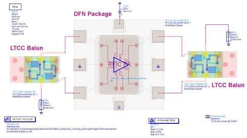
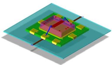
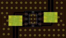
22 Example 4: Mixer on DFN Package with Merchant LTCC Balun Drop-in DFN on module layout 3D View LTCC Balun 22


23 Simulated Performance ( IC, Package, Balun ) 23
24 3. The Value of Chip/Package Co-Design Chip Package Board 24
25 Sequential vs. Co-Design Process Sequential Design Process Project Start DR1 DR2 DR3 DR4 DR1 DR2 DR3 DR1 DR2 DR3 DR4 Integration OK? N Y Done Con-current Co-Design Process DR1 DR2 DR3 DR4 Project Start DR1 DR2 DR3 Done DR1 DR2 DR3 DR4 25

26 Chip/Pkg/Module Co-Design Case Study RFIC Differential Power Amplifier Test Board Bondwires Single Ended PA Output PCB LTCC Balun Si PA LTCC Balun Single Ended PA Input Package 26


27 The Old Way, Sequential Design Process Chip Design Package Design Module Design Meet Spec? 100% 100% 100% Meet Spec? Final Integration On PC Board! Expect 100% x 100% x 100% = 100% 27


28 Let s Prove Whether The Integration Works RFIC PA + Balun RFIC PA, integrated with Ideal and LTCC Balun, meets the performance goals Blue: Ideal Balun Red: LTCC Balun Spectre Netlist Ideal to LTCC Balun Spectre Compatibility 28
29 Let s Prove Whether The Integration Works Final Integration of Balun + RFIC PA + Package 29
30 Unexpected or Unpredicted Parasitic Resonance Caught in Last Minute Final Integration Test! Unexpected parasitic resonance around 1.7 GHz How will this unexpected or unpredicted behavior impact on the development schedule? S21 S12 S21 S12 S11 S22 30

31 Last Minute Design Failure Could Impact Greatly on Design Wins and Time to Market What if, this is a design failure to meet the spec? So, will you re-spin the chip? $$$ & TTM Or re-spin the package? $$$ & TTM Or bandage the design or just blame others? Ground Through W/B Typical grounding problem with RFIC 31


32 Integrated 3D EM for Successful IC Designs MMIC/RFIC designers must take the package performance into consideration since IC design is not finished until it is packaged Integrated 3D EM allows MMIC/RFIC designers to test, verify, and optimize IC circuits with 3D packages continuously and quickly without leaving their circuit design environment Non-Integrated EM Flow Integrated EM Flow 32


33 Proposed Chip/Package/Module Co-Design (Concurrent) Process Chip Design Board Design Package Design Module Design 33
34 4. Conclusion In modern MMIC/RFIC designs, the package performance is the critical success factor for product design wins Integrated 3DEM design flow makes product design cycle shorter and much more efficient Co-design process for chip and package enables faster and cheaper product designs 34
35 For more information about Agilent EEsof EDA, visit: For more information on Agilent Technologies products, applications or services, please contact your local Agilent office. The complete list is available at: Contact Agilent at: Americas Canada (877) Latin America United States (800) Asia Pacific Australia China Hong Kong India Japan 0120 (421) 345 Korea Malaysia Singapore Taiwan Thailand Europe & Middle East Austria Belgium 32 (0) Denmark Finland 358 (0) France * *0.125 /minute Germany Ireland Israel /544 Italy Netherlands 31 (0) Spain 34 (91) Sweden Switzerland United Kingdom 44 (0) Other European Countries: Product specifications and descriptions in this document subject to change without notice. Agilent Technologies, Inc Printed in USA, August 26, EN 35
EM Insights Series. Episode #1: QFN Package. Agilent EEsof EDA September 2008
 EM Insights Series Episode #1: QFN Package Agilent EEsof EDA September 2008 Application Overview Typical situation IC design is not finished until it is packaged. It is now very important for IC designers
Innovations in EDA Webcast Series
 Welcome Innovations in EDA Webcast Series August 2, 2012 Jack Sifri MMIC Design Flow Specialist IC, Laminate, Package Multi-Technology PA Module Design Methodology Realizing the Multi-Technology Vision
--- An integrated 3D EM design flow for EM/Circuit Co-Design
 ADS users group meeting 2009 Rome 13/05, Böblingen 14-15/05, Massy 16/06 --- An integrated 3D EM design flow for EM/Circuit Co-Design Motivations and drivers for co-design Throw-The-Die-Over-The-Wall,
The wireless industry
 From May 2007 High Frequency Electronics Copyright Summit Technical Media, LLC RF SiP Design Verification Flow with Quadruple LO Down Converter SiP By HeeSoo Lee and Dean Nicholson Agilent Technologies
When Should You Apply 3D Planar EM Simulation?
 When Should You Apply 3D Planar EM Simulation? Agilent EEsof EDA IMS 2010 MicroApps Andy Howard Agilent Technologies 1 3D planar EM is now much more of a design tool Solves bigger problems and runs faster
Keysight TC GHz High Power Output Amplifier
 Keysight TC724 2-26.5 GHz High Power Output Amplifier 1GG7-8045 Data Sheet Features Wide Frequency Range: 2 26.5 GHz Moderate Gain: 7.5 db Gain Flatness: ± 1 db Return Loss: Input: 17 db Output: 14 db
Keysight TC231P 0-20 GHz Integrated Diode Limiter
 Keysight TC231P 0-20 GHz Integrated Diode Limiter 1GC1-8235 Data Sheet Features Two Independent Limiters for Single ended or Differential Signals Can be Biased for Adjustable Limit Level and Signal Detection
MEMS On-wafer Evaluation in Mass Production Testing At the Earliest Stage is the Key to Lowering Costs
 MEMS On-wafer Evaluation in Mass Production Testing At the Earliest Stage is the Key to Lowering Costs Application Note Recently, various devices using MEMS technology such as pressure sensors, accelerometers,
Keysight TC950 DC 75 GHz SPDT GaAs MMIC Switch
 Keysight TC950 DC 75 GHz SPDT GaAs MMIC Switch 1GG6-8054 Data Sheet Features Frequency Range: DC-75 GHz Insertion Loss: 2.6 db typical @ 50 GHz Isolation: 29 db typical @ 50 GHz Return Loss: >10 db (Both
Keysight TC GHz Frequency Doubler
 Keysight TC221 50 GHz Frequency Doubler 1GC1-8038 Data Sheet Features Conversion Efficiency: 12 db Typical 1/2 and 3/2 spurs: 15 dbc Typical Broad Bandwidth, 20 50 GHz Output Frequency Introduction The
Radar System Design and Interference Analysis Using Agilent SystemVue
 Radar System Design and Interference Analysis Using Agilent SystemVue Introduction Application Note By David Leiss, Sr. Consultant EEsof EDA Anurag Bhargava, Application Engineer EEsof EDA Agilent Technologies
Keysight HMMC-1002 DC 50 GHz Variable Attenuator
 Keysight HMMC-1002 DC 50 GHz Variable Attenuator 1GG7-8001 Data Sheet Features Specified frequency range: DC to 26.5 GHz Return loss: 10 db Minimum attenuation: 2.0 db Maximum attenuation: 30.0 db 02 Keysight
Keysight Technologies HMMC GHz High-Gain Amplifier
 Keysight Technologies HMMC-5620 6-20 GHz High-Gain Amplifier Data Sheet Features Wide-frequency range: 6-20 GHz High gain: 17 db Gain flatness: ± 1.0 db Return loss: Input 15 db Output 15 db Single bias
Agilent EEsof EDA.
 Agilent EEsof EDA This document is owned by Agilent Technologies, but is no longer kept current and may contain obsolete or inaccurate references. We regret any inconvenience this may cause. For the latest
Agilent HMMC-3124 DC-12 GHz Packaged High Efficiency Divide-by-4 Prescaler 1GC TR1-7" diameter reel/500 each 1GC BLK-bubble strip/10 each
 Agilent HMMC-3124 DC-12 GHz Packaged High Efficiency Divide-by-4 Prescaler 1GC1-8207-TR1-7" diameter reel/500 each 1GC1-8207-BLK-bubble strip/10 each Data Sheet Features Wide Frequency Range: 0.2-12 GHz
Solutions for Solar Cell and Module Testing
 Solutions for Solar Cell and Module Testing Agilent 663XB Power Supplies Connected in Anti-Series to Achieve Four-Quadrant Operation for Solar Cell and Module Testing Application Note Overview To fully
UWB Antenna Measurements with the 20 GHz E5071C ENA Network Analyzer
 UWB Antenna Measurements with the 20 GHz E5071C ENA Network Analyzer Application Note Minimize cost of test with the 20 GHz ENA s high performance and fast measurement speed Quickly leverage your current
Agilent 8762F Coaxial Switch 75 ohm
 Agilent 8762F Coaxial Switch 75 ohm Technical Overview DC to 4 GHz Exceptional repeatability over 1 million cycle life Excellent isolation The 8762F brings a new standard of performance to 75 ohm coaxial
 Using a Network and Impedance Analyzer to Evaluate 13.56 MHz RFID Tags and Readers/Writers Silicon Investigations Repair Information - Contact Us 920-955-3693 www.siliconinvestigations.com Application
Agilent N8480 Series Thermocouple Power Sensors. Technical Overview
 Agilent N8480 Series Thermocouple Power Sensors Technical Overview Introduction The new N8480 Series power sensors replace and surpass the legacy 8480 Series power sensors (excluding the D-model power
ADS-SystemVue Linkages
 ADS-SystemVue Linkages Uniting System, Baseband, and RF design flows for leading-edge designs Superior RF models and simulators Convenient, polymorphic algorithmic modeling, debug, and test May 2010 Page
Agilent 87075C Multiport Test Set
 Agilent 87075C Multiport Test Set Technical Overview A complete 75 Ω system for cable TV device manufacturers Now, focus on testing, not reconnecting! For use with the Agilent 8711 C-Series of network
Process Control Calibration Made Easy with Agilent U1401A
 Process Control Calibration Made Easy with Agilent U1401A Application Note This application note explains how the Agilent U1401A with simultaneous source and measure functions eases technicians calibration
Agilent AN Balanced Circuit Measurement with an Impedance Analyzer/LCR Meter/Network Analyzer Application Note
 Agilent AN 346-2 Balanced Circuit Measurement with an Impedance Analyzer/LCR Meter/Network Analyzer Application Note Introduction How a balanced circuit differs from an unbalanced circuit A balanced circuit
Flip-Chip for MM-Wave and Broadband Packaging
 1 Flip-Chip for MM-Wave and Broadband Packaging Wolfgang Heinrich Ferdinand-Braun-Institut für Höchstfrequenztechnik (FBH) Berlin / Germany with contributions by F. J. Schmückle Motivation Growing markets
Comparing Contact Performance on PCBA using Conventional Testpads and Bead Probes
 Comparing Contact Performance on PCBA using Conventional Testpads and Bead Probes White Paper Andrew Tek, Agilent Technologies Introduction This white paper captures the details of an evaluation performed
IEEE Standard Boundary Scan Testing on Agilent Medalist i3070 In Circuit Systems
 IEEE 1149.6 Standard Boundary Scan Testing on Agilent Medalist i3070 In Circuit Systems White Paper By Jun Balangue, Technical Marketing Engineer, Agilent Technologies, Inc. Abtract: This paper outlines
 Agilent PN 4395-1 Agilent 4395A Network/Spectrum/ Impedance Analyzer Silicon Investigations Repair Information - Contact Us 920-955-3693 www.siliconinvestigations.com ADSL Copper Loop Measurements Product
N2790A 100 MHz, N2791A 25 MHz and N2891A 70 MHz High-voltage Differential Probes
 N2790A 100 MHz, N2791A 25 MHz and N2891A 70 MHz High-voltage Differential Probes Data Sheet Oscilloscope users often need to make floating measurements where neither point of the measurement is at earth
Agilent 87222C/D/E Coaxial Transfer Switches dc to 26.5, 40, 50 GHz
 Agilent 87C/D/E Coaxial Transfer Switches dc to 6.5, 0, 50 GHz Technical Overview High Performance Transfer Switches for Micro wave and RF Instrumentation and Systems Exceptional repeatability for more
Agilent 4294A Precision Impedance Analyzer, 40 Hz to 110 MHz. Configuration Guide
 Agilent 4294A Precision Impedance Analyzer, 40 Hz to 110 MHz Configuration Guide Ordering Guide The following steps will guide you through configuring your 4294A. Standard Furnished Item CD-ROM Manual
A Time-Saving Method for Analyzing Signal Integrity in DDR Memory Buses
 A Time-Saving Method for Analyzing Signal Integrity in DDR Memory Buses Application Note 1591 This application note covers new tools and measurement techniques for characterizing and validating signal
Using Sonnet EM Analysis with Cadence Virtuoso in RFIC Design. Sonnet Application Note: SAN-201B July 2011
 Using Sonnet EM Analysis with Cadence Virtuoso in RFIC Design Sonnet Application Note: SAN-201B July 2011 Description of Sonnet Suites Professional Sonnet Suites Professional is an industry leading full-wave
Agilent InfiniiMax III probing system
 Agilent InfiniiMax III probing system Data Sheet World s highest speed and highest performing probe system Full 30 GHz bandwidth to the probe tip Industry s lowest probe and scope system noise Industry
Agilent U9397A/C FET Solid State Switches (SPDT)
") Agilent U9397A/C FET Solid State Switches (SPDT) U9397A 300 khz to 8 GHz U9397C 300 khz to 18 GHz Technical Overview Key Features Prevent damage to sensitive components with low video leakage < 10 mvpp
Agilent U9397A/C FET Solid State Switches (SPDT) U9397A 300 khz to 8 GHz U9397C 300 khz to 18 GHz Technical Overview Key Features Prevent damage to sensitive components with low video leakage < 10 mvpp
Agilent 8761A/B Microwave Switches
 Agilent 8761A/B Microwave Switches Technical Overview Product Description The Agilent Technologies 8761A and 8761B are single-pole, double-throw coaxial switches with excellent electrical and mechanical
Two-Way Radio Testing with Agilent U8903A Audio Analyzer
 Two-Way Radio Testing with Agilent U8903A Audio Analyzer Application Note Introduction As the two-way radio band gets deregulated, there is a noticeable increase in product offerings in this area. What
Synthesis of Optimal On-Chip Baluns
 Synthesis of Optimal On-Chip Baluns Sharad Kapur, David E. Long and Robert C. Frye Integrand Software, Inc. Berkeley Heights, New Jersey Yu-Chia Chen, Ming-Hsiang Cho, Huai-Wen Chang, Jun-Hong Ou and Bigchoug
Agilent 87405B. Preamplifier 10 MHz to 4 GHz. Technical Overview. Features. Benchtop/General Purpose Use
 Agilent 8705B Preamplifier 10 MHz to GHz Technical Overview Features db Gain 5 db Noise Figure Probe-power bias connection via probe port from Agilent s spectrum analyzers Compact Size Benchtop/General
Keysight Technologies Using a Network and Impedance Analyzer to Evaluate MHz RFID Tags and Readers/Writers
 Keysight Technologies Using a Network and Impedance Analyzer to Evaluate 13.56 MHz RFID Tags and Readers/Writers Application Note L C R f 0 = 2 1 π L C Introduction RFIDs, also called non-contact IC cards
Keysight Technologies MEMS On-wafer Evaluation in Mass Production
 Keysight Technologies MEMS On-wafer Evaluation in Mass Production Testing at the Earliest Stage is the Key to Lowering Costs Application Note Introduction Recently, various devices using MEMS technology
CPL-WB-02D3. Wide-band, directional coupler with integrated 50 ohm loaded isolated port. Features. Applications. Description.
 CPL-WB-02D3 Wide-band, directional coupler with integrated 50 ohm loaded isolated port Datasheet production data Features 50 Ω nominal input / output impedance Wide operating frequency range (2400 MHz
Keysight Technologies P9400A/C Solid State PIN Diode Transfer Switches
 Keysight Technologies P9400A/C Solid State PIN Diode Transfer Switches P9400A 100 MHz to 8 GHz PIN transfer switch P9400C 100 MHz to 18 GHz PIN transfer switch Technical Overview Key Features Minimize
CPL-WB-00C2. Wide band directional coupler with ISO port. Features. Applications. Description. Benefits
 Wide band directional coupler with ISO port Features 50 Ω nominal input / output impedance Wide operating frequency range (824 MHz to 2170 MHz) Low Insertion Loss (< 0.2 db) 34 db typical coupling factor
Signal Integrity Modeling and Simulation for IC/Package Co-Design
 Signal Integrity Modeling and Simulation for IC/Package Co-Design Ching-Chao Huang Optimal Corp. October 24, 2004 Why IC and package co-design? The same IC in different packages may not work Package is
Keysight Technologies N2792A/N2818A 200 MHz and N2793A/N2819A 800 MHz Differential Probes. Data Sheet
 Keysight Technologies N2792A/N2818A 200 MHz and N2793A/N2819A 800 MHz Differential Probes Data Sheet Introduction The Keysight Technologies, Inc. N2792A/93A and N2818A/19A differential probes provide the
InfiniiMax III probing system
 InfiniiMax III probing system Data Sheet World s highest speed and highest performing probe system Full 30 GHz bandwidth to the probe tip Industry s lowest probe and scope system noise Industry s highest
Surface Mount Package SOT-363/SC70. Pin Connections and Package Marking. AHx
 Agilent ABA-5153 3.5 GHz Broadband Silicon RFIC Amplifier Data Sheet Description Agilent s ABA-5153 is an economical, easy-to-use, internally 5-ohm matched silicon monolithic broadband amplifier that offers
Solar Array Simulation System Integration
 Solar Array Simulation System Integration Technical Overview When laying out the design of an E4360A solar array simulator (SAS) system, steps can be taken up front to ensure proper and reliable system
Agilent Correlation between TDR oscilloscope and VNA generated time domain waveform
 Agilent Correlation between TDR oscilloscope and VNA generated time domain waveform Application Note Introduction Time domain analysis (TDA) is a common method for evaluating transmission lines and has
EMDS for ADS Momentum
 EMDS for ADS Momentum ADS User Group Meeting 2009, Böblingen, Germany Prof. Dr.-Ing. Frank Gustrau Gustrau, Dortmund User Group Meeting 2009-1 Univ. of Applied Sciences and Arts (FH Dortmund) Presentation
Making a S11 and S21 Measurement Using the Agilent N9340A
 Making a S11 and S21 Measurement Using the Agilent N9340A Application Note Introduction Spectrum characteristics are important in wireless communication system maintenance. Network and spectrum analyzers
Keysight Technologies N4985A System Amplifiers
 Keysight Technologies N4985A System Amplifiers Data Sheet N4985A-P15 10 MHz to 50 GHz N4985A-P25 2 to 50 GHz N4985A-S30 100 khz to 30 GHz N4985A-S50 100 khz to 50 GHz Exceptional gain and power performance
Keysight Technologies Differences in Application Between Power Dividers and Power Splitters. Application Note
 Keysight Technologies Differences in Application Between Dividers and Splitters Application Note 02 Keysight Differences in Application Between Dividers and Splitters Application Note Introduction dividers
SD1488 RF POWER BIPOLAR TRANSISTORS UHF MOBILE APPLICATIONS
 RF POWER BIPOLAR TRANSISTORS UHF MOBILE APPLICATIONS FEATURES SUMMARY 470 MHz 12.5 VOLTS EFFICIENCY % COMMON EMITTER P OUT = 38 W MIN. WITH 5.8 db GAIN DESCRIPTION The SD1488 is a 12.5 V Class C epitaxial
Agilent N4000A, N4001A, N4002A SNS Series Noise Sources 10 MHz to 26.5 GHz
 Agilent N4000A, N4001A, N4002A SNS Series Noise Sources 10 MHz to 26.5 GHz Technical Overview Advances in Noise Figure Accuracy N4000A Used for low noise figure devices or devices sensitive to mismatch
Keysight Technologies N6850A Broadband Omnidirectional Antenna. Data Sheet
 Keysight Technologies N6850A Broadband Omnidirectional Antenna Data Sheet 02 Keysight N6850A Broadband Omnidirectional Antenna - Data Sheet Industries and Applications Spectrum monitoring and signal location,
Keysight Technologies Power of Impedance Analyzer
 Keysight Technologies Power of Impedance Analyzer - Comparison to Network Analyzer Application Note Uncover real characteristics Introduction Keysight s impedance analyzers are the only instruments on
Techniques to Achieve Oscilloscope Bandwidths of Greater Than 16 GHz
 Techniques to Achieve Oscilloscope Bandwidths of Greater Than 16 GHz Application Note Infiniium s 32 GHz of bandwidth versus techniques other vendors use to achieve greater than 16 GHz Banner specifications
Agilent 2-Port and 4-Port PNA-X Network Analyzer
 Agilent 2-Port and 4-Port PNA-X Network Analyzer N5244A - MHz to 43.5 GHz N5245A - MHz to 5. GHz with Option H29 Data Sheet and Technical Specifications Documentation Warranty THE MATERIAL CONTAINED IN
Multipurpose Lab Station by Agilent Technologies
 Multipurpose Lab Station by Agilent Technologies The Agilent Multipurpose Lab Station is an integrated system comprised of a: 1 2 3 4 5 6 7 8 Mixed signal oscilloscope (MSO) or digital signal oscilloscope
DCPL-WB-00D3. Wide-band, dual-path directional coupler with ISO port. Features. Description. Applications. Benefits
 Wide-band, dual-path directional coupler with ISO port Features 50 Ω nominal input / output impedance Wide operating frequency range: 824 MHz-2170 MHz Low insertion loss (< 0.2 db) High directivity (>
Keysight Technologies E1834E/G/J/M/Z Mounted Beam Delivery Optics. Preliminary Data Sheet
 Keysight Technologies E1834E/G/J/M/Z Mounted Beam Delivery Optics Preliminary Data Sheet The Keysight Technologies, Inc. E1834 family of beam delivery optics uses high performance mounts to meet the pointing
Agilent 87104/87106A, B, C Multiport Coaxial Switches dc to 4 GHz, dc to 20 GHz, dc to 26.5 GHz
 Agilent 87104/87106A, B, C Multiport Coaxial Switches dc to 4 GHz, dc to 20 GHz, dc to 26.5 GHz Technical Overview High performance multiport switches for microwave and RF instrumentation and systems SP4T
Agilent N8973A, N8974A, N8975A NFA Series Noise Figure Analyzers. Data Sheet
 Agilent N8973A, N8974A, N8975A NFA Series Noise Figure Analyzers Data Sheet Specifications Specifications are only valid for the stated operating frequency, and apply over 0 C to +55 C unless otherwise
Introducing ENA Series E5061B-1x5/2x5/1x7/2x7 RF NA Options 100 khz to 1.5 / 3 GHz
 Introducing ENA Series E5061B-1x5/2x5/1x7/2x7 RF NA Options 100 khz to 1.5 / 3 GHz Suitable for manufacturing The successor for E5061A/62A RF NA options* E5061B-115, 215, 135, 235: 50 Ω E5061B-117, 217,
Features. = +25 C, Vdd = 5V, Vgg1 = Vgg2 = Open
 v3.117 HMC441LM1 Typical Applications The HMC441LM1 is a medium PA for: Point-to-Point Radios Point-to-Multi-Point Radios VSAT LO Driver for HMC Mixers Military EW & ECM Functional Diagram Vgg1, Vgg2:
CPL-WB-01D3. Wide-band directional coupler with ISO port. Features. Applications. Description. Benefits
 Wide-band directional coupler with ISO port Features 50 Ω nominal input / output impedance Wide operating frequency range (824 MHz to 2170 MHz) Low insertion loss (< 0.2 db) 26 db coupling factor High
Agilent EEsof EDA.
 Agilent EEsof EDA This document is owned by Agilent Technologies, but is no longer kept current and may contain obsolete or inaccurate references. We regret any inconvenience this may cause. For the latest
Agilent MXG Signal Generators
 Agilent MXG Signal Generators N5161A MXG ATE Analog N5162A MXG ATE Vector N5181A MXG Analog N5182A MXG Vector Configuration Guide This guide is to assist in the ordering process for the MXG analog and
TSH MHz to 1GHz AMPLIFIER. 1.5V to 5V OPERATING VOLTAGE 28dB 450MHz
 TSH69 4MHz to 1GHz AMPLIFIER 1.5V to 5V OPERATING VOLTAGE 28dB GAIN @ 3V @ 45MHz. 2dB GAIN @ 3V @ 9MHz +13.5dBm OUTPUT POWER (P1dB) BIAS PIN FOR CURRENT ADJUST & AMPLIFIER DISABLE. ADJUSTABLE OUTPUT POWER
Soldering a P7500 to a Nexus DDR Component Interposer
 Soldering a P7500 to a Nexus DDR Component Interposer Introduction This document shows an example of how to solder P7500 tips to the oscilloscope version of a Nexus DDR Component Interposer board. The
Keysight Technologies Accurate Capacitance Characterization at the Wafer Level
 Keysight Technologies Accurate Capacitance Characterization at the Wafer Level 4080 Series Parametric Test Systems Application Note Introduction The continuing trend of decreasing device geometries of
N2820A/21A High-Sensitivity, High Dynamic Range Current Probes
 N2820A/21A High-Sensitivity, High Dynamic Range Current Probes Data Sheet See the details without losing sight of the big picture Key features and specifications Measure currents as low as 50 µa Measure
Application Note 1330
 HMPP-3865 MiniPAK PIN Diode High Isolation SPDT Switch Design for 1.9 GHz and 2.45 GHz Applications Application Note 133 Introduction The Avago Technologies HMPP-3865 parallel diode pair combines low inductance,
Discovering New Techniques of Creating, Editing, and Transferring Arbitrary Waveforms
 Discovering New Techniques of Creating, Editing, and Transferring Arbitrary Waveforms Introduction Today, during the designing of electronic components and circuits for computers, peripherals, and consumer
Keysight Technologies Understanding the SystemVue To ADS Simulation Bridge. Application Note
 Keysight Technologies Understanding the To Simulation Bridge Application Note Introduction The Keysight Technologies, Inc. is a new system-level design environment that enables a top-down, model-based
Agilent EEsof EDA.
 Agilent EEsof EDA This document is owned by Agilent Technologies, but is no longer kept current and may contain obsolete or inaccurate references. We regret any inconvenience this may cause. For the latest
Measuring Vgs on Wide Bandgap Semiconductors APPLICATION NOTE
 Measuring Vgs on Wide Bandgap Semiconductors This application note focuses on accurate high-side V GS measurements using the IsoVu measurement system. The measurements described in this application note
Agilent NFA Noise Figure Analyzer
 Agilent NFA Noise Figure Analyzer Configuration Guide Dedicated Noise Figure Analyzer Hard specifications to 26.5 GHz Works with N4000A SNS or 346 Series noise sources Noise figure measurements to 110
Evaluation of Package Properties for RF BJTs
 Application Note Evaluation of Package Properties for RF BJTs Overview EDA simulation software streamlines the development of digital and analog circuits from definition of concept and estimation of required
Agilent U1881A and U1882A Power Measurement Application for Agilent InfiniiVision and Infiniium Oscilloscopes
 Agilent U1881A and U1882A Power Measurement Application for Agilent InfiniiVision and Infiniium Oscilloscopes Data Sheet Fast, automatic and reliable characterization of switching mode power devices Today
DCPL-WB-02D3. Wide-band, dual-path directional coupler with integrated 50 ohm loaded isolated port. Features. Applications. Description.
 Wide-band, dual-path directional coupler with integrated 50 ohm loaded isolated port Datasheet production data Features 50 Ω nominal input / output impedance Wide operating frequency range: 2400 MHz-5850
Keysight Technologies Improving the Test Efficiency of MEMS Capacitive Sensors Using the E4980A Precision LCR Meter.
 Keysight Technologies Improving the Test Efficiency of MEMS Capacitive Sensors Using the E4980A Precision LCR Meter Application Note Introduction Exceptional accuracy and repeatability DC bias function
Keysight M9485A PXIe Multiport Vector Network Analyzer
 Keysight M9485A PXIe Multiport Vector Network Analyzer 02 Keysight M9485A PXIe Multiport Vector Network Analyzer - Brochure High-Performance PXI Multiport Vector Network Analyzer (VNA) Innovative solution
Keysight Technologies Improving Test Efficiency of MEMS Electrostatic Actuators Using the E4980A Precision LCR Meter.
 Keysight Technologies Improving Test Efficiency of MEMS Electrostatic Actuators Using the E4980A Precision LCR Meter Application Note Introduction Highly accurate and repeatable measurements DC bias function
W2360EP/ET SIPro Signal Integrity EM Analysis W2359EP/ET PIPro Power Integrity EM Analysis
 Keysight Technologies Advanced Design System (ADS) W2360EP/ET SIPro Signal Integrity EM Analysis W2359EP/ET PIPro Power Integrity EM Analysis Data Sheet Composite EM technology delivers high-accuracy and
7 Hints That Every Engineer Should Know When Making Power Measurements with Oscilloscopes.
 7 Hints That Every Engineer Should Know When Making Power Measurements with Oscilloscopes. Achieving maximized measurement dynamic range 1) Use averaging to increase measurement resolution 2) Use high-resolution
MXG X-Series Signal Generator N5183B Microwave Analog
 MXG X-Series Signal Generator N5183B Microwave Analog Configuration Guide This configuration guide will help you determine which performance, software applications, accessories, and services to include
Introduction. Part 1. Introduction...2
 Keysight Technologies Simple Scalar Network Analysis of Frequency Converter Devices using the U2000 USB Power Sensor Series with the ENA Network Analyzer Application Note Introduction This application
N2790A 100 MHz, N2791A 25 MHz and N2891A 70 MHz High-voltage Differential Probes
 N2790A 100 MHz, N2791A 25 MHz and N2891A 70 MHz High-voltage Differential Probes Data Sheet Oscilloscope users often need to make floating measurements where neither point of the measurement is at earth
Agilent MXG Signal Generators
 Agilent MXG Signal Generators N5161A MXG ATE Analog N5162A MXG ATE Vector N5181A MXG Analog N5182A MXG Vector Configuration Guide This guide is to assist in the ordering process for the MXG analog and
Agilent E4438C/E8267D Option 422 Scenario Generator for GPS
 Agilent E4438C/E8267D Option 422 Scenario Generator for GPS Technical Overview Create GPS Scenarios with Ease The Option 422 scenario generator software enhances the functionality of the Global Positioning
BAL-2593D5U 50 / 50+j50 balun transformer for 2.45 GHz ISM band Features Application Description Benefits
 50 / 50+j50 balun transformer for 2.45 GHz ISM band Features 50 Ω nominal Input / 50+j50 output differential impedance Lo insertion loss Lo amplitude imbalance Lo phase imbalance Small footprint: BAL-2593D5U
Keysight Technologies Electronic Calibration (ECal) Modules for Vector Network Analyzers
 Modules for Vector Network Analyzers") Keysight Technologies Electronic Calibration (ECal) Modules for Vector Network Analyzers N4690 Series, 2-port Microwave ECal 85090 Series, 2-port RF ECal N4430 Series, 4-port ECal N7550 Series, 2-port
Keysight Technologies Electronic Calibration (ECal) Modules for Vector Network Analyzers N4690 Series, 2-port Microwave ECal 85090 Series, 2-port RF ECal N4430 Series, 4-port ECal N7550 Series, 2-port
Keysight 8474B/C/E Planar-Doped Barrier Diode Detectors 0.01 to 50 GHz. Data Sheet
 Keysight 8474B/C/E Planar-Doped Barrier Diode Detectors.1 to 5 GHz Data Sheet Introduction Features and Description Exceptional flatness Broadband from.1 to 5 GHz Extremely temperature stable Environmentally
Keysight E5063A ENA Series Network Analyzer
 Keysight E5063A ENA Series Network Analyzer 100 khz to 500 M/1.5 G/3 G/4.5 G/6.5 G/8.5 G/14 G/18 GHz Configuration Guide 02 Keysight E5063A ENA Series Network Analyzer - Configuration Guide Ordering Guide
SD1275 RF POWER BIPOLAR TRANSISTORS VHF MOBILE APPLICATIONS. FEATURES SUMMARY 160 MHz 13.6 VOLTS COMMON EMITTER P OUT = 40 W MIN.
 RF POWER BIPOLAR TRANSISTORS VHF MOBILE APPLICATIONS FEATURES SUMMARY 1 MHz 13.6 VOLTS COMMON EMITTER P OUT = W MIN. WITH 9 db GAIN Figure 1. Package DESCRIPTION The SD1275 is a 13.6 V Class C epitaxial
74LX1G04BJR LOW VOLTAGE CMOS SINGLE INVERTER WITH 5V TOLERANT INPUT
 LOW VOLTAGE CMOS SINGLE INVERTER WITH 5V TOLERANT INPUT 5V TOLERANT INPUTS HIGH SPEED: t PD = 4.2ns (MAX.) at V CC =3V LOW POWER DISSIPATION: I CC =1µA (MAX.)atT A =25 C POWER DOWN PROTECTION ON INPUTS
Agilent AT Up to 6 GHz Low Noise Silicon Bipolar Transistor Data Sheet
 Agilent AT-135 Up to GHz Low Noise Silicon Bipolar Transistor Data Sheet Description Agilent s AT-135 is a general purpose NPN bipolar transistor that offers excellent high frequency performance. The AT-135