INVESTIGATING THE CAPABILITIES OF SEL 787 TRANSFORMER PROTECTION RELAY USING LOW LEVEL SIMULATORS.
|
|
|
- Dominick Preston
- 6 years ago
- Views:
Transcription

1 INVESTIGATING THE CAPABILITIES OF SEL 787 TRANSFORMER PROTECTION RELAY USING LOW LEVEL SIMULATORS. Thesis submitted to the School of Engineering and Information Technology, Murdoch University in partial fulfilment of the requirements for the degree of Bachelor of Engineering Tendai Raymond Dube Supervisor: Assoc. Prof. Graeme Cole Co-supervisor: Dr. Gregory Creebin 7/1/2016
2 STATEMENT OF ORIGINALITY This thesis is my own original work. To the best of my knowledge, I hereby certify that the work in this thesis contains no material previously written by another person or submitted for the award of any other degree in any university. All literature and information sources derived from unpublished and published work of others has been acknowledged and indicated in this thesis. 09 /01/2016 SIGNED DATE i
3 Abstract Protection relays play an integral part in electrical power systems. They monitor and detect abnormal system conditions and initiate the operation of protective devices like circuit breakers to take corrective action and restore the power system to its normal state. Over the years, the technology has evolved from the old electromechanical-based relays to the new microprocessor-based relays also known as intelligent electronic devices, such as the SEL 787 transformer protection relay. Correct operation of these devices is critical as malfunction or incorrect operation might lead to severe damage to protected equipment and costly power outages. In commissioning, maintenance and training fields, the correct operation and accuracy verification is determined through carrying out fault simulations on the relay using different types of test equipment or simulators. This thesis investigates the capabilities of SEL 787 relay by using low level fault simulators and setting the foundation for the development of a National Instrument CompactDaq and LabVIEW fault simulator. The thesis comprises the following three main parts: ii
4 Part 1: SEL 787 Transformer protection relay In this thesis, research has been carried out on the design and application of the SEL 787 relay in transformer protection. The hardware components and the software platform used by the relay has been analysed. Investigation of the software tools to facilitate efficient simulations and hence explore the functionality of the relay has been conducted. Part 2: Fault simulators / Test equipment Focuses on the different types of fault simulators in particular low level simulators like the SEL RTS system. Simulations where carried out on the SEL 787 relay using the SEL RTS system. The simulation results were analysed using standards and manufacturer specifications. Part 3: LabVIEW CompactDaq Simulator Involves the proposed design of a low level simulator using the CompactDaq modules and LabVIEW software. Analysis of the CompactDaq modules was conducted. Tests were successfully carried out using the CompactDaq system via NI Max test panel on the SEL 787 protection relay. iii
5 Acknowledgements I would like to express my sincere gratitude to my project supervisor, Associate Professor Graeme Cole, for his support and guidance throughout my studies at Murdoch University. Many thanks for assistance and support to Mr Iafeta Jeff Laava, Mr Will Stirling and Mr John Boulton, technical Officers at Murdoch University, and to my fellow thesis students. I would like to thank my late mother Mrs G Dube, umasibindi for inspiring me to get started and keep going. Finally, I would like to thank my dear wife, Bukamu Dube and my son, Jayden Tendai Dube, for their patience, love and understanding throughout my years of study. iv
6 Contents ABSTRACT... II ACKNOWLEDGEMENTS... IV LIST OF FIGURES... XI LIST OF TABLES... XV LIST OF EQUATIONS... XV LIST OF ABBREVIATIONS... XVI CHAPTER 1... PROJECT INTRODUCTION BACKGROUND OBJECTIVES... 2 CHAPTER 2... PROTECTION SCHEME PURPOSE ATTRIBUTES OF A GOOD PROTECTION SCHEME PROTECTION RELAYS ELECTROMECHANICAL SOLID STATE MICROPROCESSOR-BASED RELAYS... 9 v
7 CHAPTER 3...PROTECTION RELAY FAULT SIMULATORS HIGH LEVEL SIMULATORS LOW LEVEL SIMULATORS CHAPTER 4... POWER TRANSFORMER POWER TRANSFORMER CONSTRUCTION PRINCIPLE OF OPERATION TRANSFORMER MAGNETISATION CHARACTERISTICS POWER TRANSFORMER FAULTS PHASE-TO-PHASE FAULTS: CORE FAULTS: TANK FAULTS: INTERTURN FAULTS: CHAPTER 5... SCHWEITZER ENGINEERING LABORATORIES, INC SEL ACSELERATOR QUICK SET SETTINGS SETTINGS EDITOR GROUP SETTING SETTINGS COMPARE TERMINAL vi
8 5.4 HUMAN MACHINE INTERFACE HMI SEL LOGIC EVENT ANALYSIS CHAPTER 6... SEL 787 PROTECTION RELAY OVERVIEW HARDWARE I/O CARDS FRONT PANEL WIRING CONFIGURATION CHAPTER 7... PROTECTION RELAY STANDARDS AND TESTING PROTECTION RELAY STANDARDS RELAY TESTING AND FAULT SIMULATIONS TYPES OF TESTS TEST EQUIPMENT FAULT DATA ARRANGEMENT SEL SAFETY SELF-TEST SIMULATION METHODOLOGY vii
9 CHAPTER 8... SEL 787 PROTECTION RELAY ELEMENTS CURRENT BASED PROTECTION ELEMENTS PHASE OVERCURRENT PROTECTION NEGATIVE PHASE SEQUENCE RESIDUAL OVERCURRENT PROTECTION BREAKER FAILURE PROTECTION DIFFERENTIAL PROTECTION PRINCIPLE OF OPERATION DIFFERENTIAL RELAY CONFIGURATION DIFFERENTIAL RELAY SETTING O87P DIFFERENTIAL ELEMENT U87P UNRESTRAINED DIFFERENTIAL ELEMENT DIFFERENTIAL ELEMENT SLOPE DIFFERENTIAL ELEMENT SLOPE MAGNETIZATION INRUSH SUPPRESSION OUT OF ZONE / THROUGH FAULT OPERATION SUPPRESSION RESTRICTED EARTH FAULT PROTECTION VOLTS/HERTZ...88 CHAPTER 9... RESULTS AND ANALYSIS INSTANTANEOUS OVERCURRENT viii
10 9.2 NEGATIVE SEQUENCE OVERCURRENT RESIDUAL GROUND OVERCURRENT BREAKER FAILURE UNRESTRAINED DIFFERENTIAL ELEMENT RESTRAINED DIFFERENTIAL SLOPE 1 RESTRAINED DIFFERENTIAL ELEMENT SLOPE 2 RESTRAINED DIFFERENTIAL ELEMENT THROUGH FAULT MONITOR CHAPTER LABVIEW/COMPACTDAQ SYSTEM COMPACTDAQ NI MAX SIGNAL OUTPUT MEASUREMENT AND ANALYSIS TESTING RELAY USING NI MAX CHAPTER CONCLUSION 123 CHAPTER FUTURE WORK 124 CHAPTER REFERENCES 125 ix
11 CHAPTER APPENDICES APPENDIX A COMPACTDAQ WIRING CONNECTION APPENDIX B ANSI/IEEE DIFFERENTIAL RELAY PROTECTION FUNCTIONS APPENDIX C SEL 787 RELAY SPECIFICATIONS APPENDIX D OVERCURRENT PROTECTION ELEMENT SIMULATION RESULTS APPENDIX E NEGATIVE SEQUENCE ELEMENT SIMULATION RESULTS APPENDIX G RESIDUAL GROUND (50G) ELEMENT SIMULATION RESULTS APPENDIX G UNRESTRAINED DIFFERENTIAL PROTECTION (87) ELEMENT SIMULATION RESULTS x
12 List of Figures Figure 1 Protection scheme components... 5 Figure 2 General arrangement of a microprocessor relay... 9 Figure 3 Labvolt high level simulator Figure 4 Low level protection relay simulator set up [8] Figure 5 Low level protection relay simulator Figure 6 Transformer principle of operation [6] Figure 7 Transformer magnetisation curve [6] Figure 8 Transformer steady state operation [6] Figure 9 Transformer transient operation on energisation [6] Figure 10 Transformer inter-turn fault [6] Figure 11 SEL relay setting editor page Figure 12 SEL 787 terminal window showing setting change Figure 13 SEL787 Group settings Figure 14 SEL 787 group setting selection Figure 15 Acselerator Terminal tab [9] Figure 16 SEL protection relay logic structure overview [9] Figure 17 SEL programing language in structured text and decompiled to function block Figure 18 Terminal Event Report [20] Figure 19 Event Oscillography...33 Figure 20 SEL transformer protection series Figure 21 SEL 787 relay I/O cards [9] Figure 22 SEL 787 rear view slots [9] Figure 23 SEL 787 relay at Murdoch University rear view Figure 24 SEL 787 relay side view information template xi
13 Figure 25 SEL 787 front panel [9] Figure 26 Labvolt relay fault simulation setup [13] Figure 27 Analog current card Figure 28 Slot Z Input circuit board Figure 29 Test cable input connection Figure 30 State sequence test template [8] Figure 31 Relay self- test report Figure 32 Ramp testing Figure 33 Inverse time current characteristic equations [9] Figure 34 Torque control switch logic for overcurrent element [9] Figure 35 SEL 787 Current protection elements [9] Figure 36 Fault simulation template Figure 37 Obtaining Sequence quantities in Microprocessor-based relays Figure 38 Negative Sequence 50Q [9] Figure 39 Negative Sequence overcurrent settings editor Figure 40 Simulation template Negative Sequence Element Figure 41 Residual element 50G [9] Figure 42 Simulation template residual element Figure 43 Breaker failure logic [9] Figure 44 SEL 787 Breaker failure settings editor Figure 45 Transformer differential protection [9] Figure 46 Operating Characteristic [9] Figure 47 SEL 787 Configuration settings Figure 48 Transformer differential settings Figure 49 SEL 787 Differential element logic [24] Figure 50 Test template for unrestrained differential element xii
14 Figure 51 Three phase and single phase fault simulation Figure 52 Slope 2 test card Figure 53 Harmonic blocking logic [9] Figure 54 In zone and out of zone faults Figure 55 Transformer Time/ Current through fault curves [9] Figure 56 Transformer through fault [9] Figure 57 Test template for through fault simulation Figure 58 Restricted earth fault protection [10]...87 Figure 59 Terminal window showing assertion of overcurrent relay word bit Figure 60 SER showing operation of overcurrent element Figure 61 SER showing time delay for overcurrent Figure 62 Terminal window showing assertion of negative sequence relay word bit Figure 63 Residual overcurrent setting page Figure 64 Test template for residual overcurrent Figure 65 Terminal window showing assertion of residual ground overcurrent relay word bit Figure 66 SER showing operation of residual overcurrent element Figure 67 Assertion of breaker failure Figure 68 SER indicating operation of the breaker failure element Figure 69 Unrestrained differential element operation Figure 70 Restrained differential element simulation template and results Figure 71 Slope 1 differential element operation results Figure 72 Restrained element relay word bit activation Figure 73 SER report for restrained element operation Figure 74 Slope 1 Differential simulation values in primary values Figure 75 Slope 2 differential element operation results Figure 76 SER report for restrained element slope 2 operation xiii
15 Figure 77 Slope 2 Restrained element relay word bit activation Figure 78 Slope 2 Differential simulation values in primary values Figure 79 Through fault simulation metering overview Figure 80 Differential metering view through fault Figure 81 Summary of through fault events Figure 82 Through fault relay word bit assertion Figure 83 Ethernet CompactDaq chassis [26] Figure 84 CompactDaq Modules [26] Figure 85 CompactDaq test setup Figure 86 NI Max test panel Figure 87 Signal analysis test setup Figure 88 Initial test simulation of output voltages Figure 89 Maximum Output Voltages Figure 90 NI Max test platform Figure 91 Fault simulation using CompactDaq system xiv
16 List of Tables Table 1 Phase overcurrent settings List of Equations Equation 1 Slope restraint value calculation [27] Equation 2 Winding 1 test current in per unit [27] Equation 3 Winding 2 test current in per unit [27] Equation 4 Winding 1 test current in Amps [27]...78 Equation 5 Winding 2 test current in Amps [27]...78 Equation 6 Slope 2 test point [27] Equation 7 Slope 2 Winding 1 test current per unit [27] Equation 8 Slope 2 Winding 2 test current per unit [27] Equation 9 Slope 2 Winding 1 test current in Amps [27] Equation 10 Slope 2 Winding 2 test current in Amps [27] Equation 11 Differential operate current [9] xv
17 List of Abbreviations AC - Alternating current DC Direct current CT -Current transformer CVT-Capacitor Voltage Transformers EMF-Electromotive force IM Magnetization Current INOM-Nominal Current BIL Basic Insulation Level HMI- Human machine interface PROM, Programmable read only memory ms, Millisecond REF-Restricted Earth fault RTD Resistance temperature device SEL Schweitzer Engineering Laboratories SER Sequential Event Report xvi
18 VT-Voltage transformer xvii
19 Chapter 1 Project Introduction The three phase power transformer is the most critical link in power system networks. The transformer links generation and transmission by stepping up generated voltages to transmission levels. The transmission voltages are in turn stepped down to distribution voltage levels [1]. Protection of three phase transformers from fault currents is done by complex protection systems. One of the key elements of these systems is the protection relay. Protection relays have the ability to detect fault currents and initiate the operation of a circuit breaker which interrupts or disconnects the fault current hence protecting the transformer. Protection relays have developed over the years from the old electromechanical relays to numeric relays and now the microprocessor-based relays. The accuracy in metering, monitoring and operation of the protection relays is of utmost importance in preventing or minimizing damage to faulty equipment [3]. 1
20 1.1 Background To determine the accuracy and the functionality of the relays in commissioning, maintenance and education purposes, various brands of simulators have been developed. The most popular brands simulators used in industry are Megger, Omicron and Doble. There are two main types of fault simulators: High level simulators shown in Figure 3, and low level simulators like the Schweitzer Engineering Laboratories Relay Testing System (SEL RTS) system shown in Figure 5. The main difference between the two is the low level simulators bypass the analog input transformers and lower analog voltage inputs and currents are used in the simulation process [8]. Previous ENG 454 and thesis students at Murdoch University have used the Labvolt system, a high level simulator for fault simulation, to demonstrate the functionality of the SEL relays. Other students had begun the development of a National Instrument CompactDaq system fault simulation system with limited success [13]. Following on from some of those previous students recommendations, this project will endeavour to continue on with the development of the system by using a different approach that is described in detail in Chapter 10 of this thesis [13]. 1.2 Objectives The aim of the project is to gain an in-depth understanding of the capability and functionality of the SEL 787 transformer protection relay available at Murdoch 2
21 University through carrying out tests and simulations on the relay using the low level simulator SEL RTS test system. Documentation of the research and findings from this report will aid present and future Industrial Computer Systems students at Murdoch University to have a better understanding of the transformer protection relay. A further aim is to advance the understanding of the use of low level simulators in testing protection relays. Low level simulators, as shown in Figure 5, facilitate fault simulation in protection by bypassing the protection relay input current and voltage transformers, hence eliminating the use of large amplifiers. This project aims to contribute to an ongoing goal of eventually developing a CompactDaq and LabVIEW protection relay simulator. This will assist engineering students at Murdoch University and others in understanding the capabilities of the SEL protection relays as the simulator will provide a faster and more efficient way of carrying out fault simulations. The relay s capabilities in protection, monitoring and metering are thus explored. 3
22 Chapter 2 Protection Scheme With the advancement in technology, protection relay systems have become more complex. The design of the systems and the core components has evolved to provide more effective and efficient systems. This chapter looks at the aims and requirements of a protection system together with the main components. 2.1 Purpose A protection scheme is a system of plant and equipment responsible for detecting abnormal conditions in electrical power systems and initiate the operation of switchgear to isolate the faulted equipment in the shortest time possible. This reduces damage on the faulted equipment and stops the effects of the fault from affecting other functioning parts of the power system [2]. There are two main types of protection schemes, unit and non-unit protection schemes. Unit schemes of protection operate only for faults within a clearly demarcated zone. There is no time coordination required with other protection systems in the power system. On the other hand, non-unit protection schemes have to be coordinated with other protection systems in the overall power system. Figure 1 shows the core components of a typical protection scheme [2]. 4
: these reduce the high values of fault currents which result under fault conditions")

23 Protected Plant or Equipment Transformer Generator Motor Instrument Transformers CT VT CVT Protection Relay ABB GE Schneider SEL Siemens Circuit Breaker Figure 1 Protection scheme components The main components of a protection scheme are described below: Current transformers (CT): these reduce the high values of fault currents which result under fault conditions to suitable values for protection relay operation. Thus, the main purpose of the current transformer in protection systems is to provide currents to the control and protection circuits which are proportional to the power system currents [4]. Voltage transformers (VT): these step down the system voltage to lower scaled values to be used in control and protection circuits. 5
24 Capacitor voltage transformers (CVT) have a capacitance voltage divider which steps down extra high voltages to low voltages [4]. Protection relay: the device, which is activated by appropriate system parameters, for example, current and voltage. The relay indicates an abnormal condition in the power system and initiates the operation of a protection device, for example, a circuit breaker. There are several manufactures of these devices including Siemen and SEL, as indicated in Figure 1 above [2]. Circuit breakers: these close and open the electrical circuit under both normal and fault conditions. The circuit breaker operation under fault conditions is usually initiated by the protection relay operation [6]. 2.2 Attributes of a good protection scheme Protection systems in most cases do not prevent damage to the faulted equipment during a fault but rather minimise the damage and the effects of the fault on the entire electric circuit. The following are the attributes of a good protection system: Reliability: the protection scheme has to be dependable and operate when required as per design specifications. Incorrect operation of the protection scheme may lead to a disastrous situation with damage to plant and equipment. Reliability of the protection system can be affected by the following factors: incorrect design, incorrect installation and deterioration of the protection equipment over time [2]. 6
25 Speedy isolation: to minimise damage to faulted equipment and prevent system instability, the protection system has to isolate the fault as quickly as possible. Isolation of the disturbance in the shortest amount of time ensures continuity of power supply in the functioning parts of the power system. [2] Sensitivity: this refers to the minimum amount of system quantities (for example, current) required to activate the protection system when an abnormal condition arises in the power system. A protection system with a very low operating current is said to be very sensitive. [2] Stability: this mainly refers to unit schemes of protection which are only required to operate for faults occurring within a clearly demarcated region and not operate for faults outside the protected zone. [2] Selectivity: this is also referred to as discrimination and refers to the protection system operating only for the faulty part of the electrical network, isolating it and leaving the healthy parts of the circuit with supply. [2] Economical: it is imperative to have appropriate levels of protection for plant and equipment at an appropriate cost. The degree of protection of a piece of equipment has to be weighed against the cost of the equipment and the cost of loss of power supply to the network. The degree of protection usually increases with the value of equipment being protected as the repair or replacement cost of the equipment are high. [2] 7
26 2.3 Protection Relays Electromechanical These relays are made of mechanical, electrical and magnetic components and the majority are of the moveable coil type. The principle of operation of these relays is based on the establishment of torque, produced by the interaction of magnetic flux, which is of a magnitude proportional to the value of current and voltage being measured. These types of protection relays are very reliable and robust, however, they are less accurate compared to solid state relays and deteriorate over time due to mechanical moving parts getting worn. [7] Solid State Over the years, the development of semiconductors and associated electronic advances has led to the design of numeric or solid state protection relays. These relays are more accurate, consume less power, occupy less place on installation, and are more resistant to vibrations and shock compared to the electromechanical relays. The downside to the solid state relays is that they require an independent power supply and are more affected by humidity and temperature. [21] 8

27 2.3.3 Microprocessor-based Relays The growing intricacy in modern power networks has necessitated the development of microprocessor-based relays with sophisticated characteristics. These protection relays, also called intelligent electronic devices, have high-performance microprocessors which have the capabilities of performing all the protection functions done by solid state relays with greater speed and efficiency [7]. Figure 2 shows the typical general arrangement of microprocessor-based relays. Figure 2 General arrangement of a microprocessor relay The main components of a microprocessor-based relay are as follows: 9
28 Input module: this consists of analog filters, signal conditioner and analog to digital converters. Signals from the power system are captured and sent to the microprocessor via this module [7]. Microprocessor: the main purpose of this is to process the protection relay algorithms. It consists of two memory components: random access memory responsible for storing information during the processing of protection algorithms; and read only memory which stores data permanently [7]. Output module: output signals from the microprocessor are conditioned and sent to the external elements which it controls [7]. Communication module: consists of series and parallel ports which facilitate connection of protection relays with communication and control systems [7]. 10
29 Chapter 3 Protection relay fault simulators After manufacture, on installation and during maintenance, protection relays are tested for correct operation. This chapter provides an overview of the different types of test equipment used to verify the correct operation of these relays. Protection relay test sets or simulators are the pieces of equipment used to measure the accuracy and demonstrate the full functionality of the relays. The modern day microprocessor protection relays have multiple functions and require sophisticated test simulators with hardware and software to comprehensively analyze the operation of the relay through simulation of real life conditions. There are several types used in industrial applications, in commissioning the relays in new installations and maintenance testing in already established installations [4].The commonly used ones include the Doble F6150, Omicron CMC 365 and Megger MPRT. For educational purposes, the most popular simulator is the Labvolt system, shown in Figure 3, which is available at Murdoch University. The fault simulators can be categorized into two main groups; high level and low level fault simulators. 11

30 Figure 3 Labvolt high level simulator 3.1 High level simulators These simulators have the capability of simulating different fault conditions through hardware and software and monitor the performance of the protection relay. The hardware components consist of analog outputs, binary outputs and binary inputs and communication interface for the associated software. The software is used to control the hardware, monitor and record the protection relay performance during the simulation. The simulation process mimics real life analog inputs to the relay from CTs and VTs and monitors the operation of the relay via relay indicators and output contacts of the relay s changing state [4]. 12
31 3.2 Low level simulators The main purpose of these simulators is to supply the protection relay with voltage and current inputs that resemble fault conditions and monitor how the relay responds in these situations. The main difference between the two is that the low level simulators bypass the analog input transformers and lower analog voltage inputs and currents are used in the simulation process [8]. For example, the SEL RTS low level simulator provides low voltage AC signals to the protection relay microprocessor via the relay test interface on the analog input circuit board as shown in Figure 4. The simulators usually come with the associated software which is used to control, monitor and record the simulation results. For the SEL RTS simulator, the software is called SEL These simulators are less expensive than the high level simulators [8]. 13

32 Figure 4 Low level protection relay simulator set up [8] Figure 5 Low level protection relay simulator ` 14
33 Chapter 4 Power Transformer Invented towards the end of the nineteenth century the power transformer has become a vital link in today s transmission and distribution systems. This chapter reviews the theory of principle of operation and the different type of faults which can occur on transformers. 4.1 Power transformer construction A power transformer is a static electrical device used to step up or step down voltage. It consists mainly of two windings: the primary and the secondary windings which are electrically isolated but magnetically linked through a magnetic core made of insulated laminations. The insulated laminations are usually made from silicon steel which increases the magnetic coupling due to its high magnetic permeability properties. 15
34 4.2 Principle of operation A transformer operates on the principles of electromagnetic induction. When an alternating voltage is applied to the primary windings, self-induction occurs on the primary windings and the changing alternating current in the primary winding induces an EMF in the secondary winding, with the process called mutual induction. The silicon steel core serves to provide a very low reluctance path for the magnetic flux. The effect of the magnetic flux is to generate a mutually induced EMF in the secondary winding which is not supplied with the alternating voltage. This is illustrated in Figure 6 [6]. 16
35 Figure 6 Transformer principle of operation [6] Transformer magnetisation Characteristics During normal operation, the transformer follows the typical magnetization curve shown in Figure 7. 17
36 Figure 7 Transformer magnetisation curve [6] Transformers are usually operated close to the knee point of the characteristic to get the best efficiency. Increasing the terminal voltage leads to the saturation of the core and excessive magnetization currents being drawn. Figure 8 shows the relationship between the voltages V, magnetization current IM and ф magnetic flux under steady state conditions [6]. 18
37 Figure 8 Transformer steady state operation [6] On energization when the voltage is at zero, the magnetic flux demand is very high and can be twice the normal magnetic flux. This causes a very high magnetising current to flow, as illustrated in Figure 9. This high magnetising current (IM) is also known as the transformer inrush current. The presence of residual flux or remanent flux can further increase the magnitude of this current on energization [6]. 19
38 Figure 9 Transformer transient operation on energisation [6] 4.3 Power transformer faults Phase-to-Phase faults: These faults are rare on transformers and can be caused by both internal and external conditions. Insulation breakdown due to mechanical stress and overheating can cause phase to phase and phase to earth faults. External conditions which can lead to phase to phase faults include overloading, overvoltage and other power system faults. Internal conditions include ageing insulation and presence of contaminants in insulating medium [2]. 20
39 4.3.2 Phase-to-Earth faults: These faults occur when the transformer windings get into contact with earth or any other conductive material connected to earth. Insulation breakdown due to ageing, poor workmanship and overheating can cause these type of faults Core faults: The magnetic or iron circuit of the transformer made of insulated laminated silicon steel has bolts which clamp the laminations together. The bolts are insulated from the laminations and if this insulation breaks down, high eddy currents may flow which cause overheating in the transformer. Power system over voltages may lead to high magnetization currents that produce flux from the highly saturated core, which is diverted to the clamping bolts. The bolts usually have low flux circulation but the high flux can result in very high temperatures emanating from the bolts. The high temperatures cause damage to the insulation leading to the short-circuiting of the core laminations [6] Tank faults: Oil filled transformers are housed in tanks containing insulating oil which completely covers the windings and the core. The main purpose of the oil is to cool the transformer; it also acts as an insulating medium. The loss of oil via leaks can lead to 21
40 overheating of the transformer and insulation reduction. Overheating of the transformer causes break down of insulation in the winding and results in short circuit faults [2] Inter-turn Faults: Insulation between turns can break down due several factors which include overheating, mechanical stress from over voltages and ageing of the insulation which can be made worse by the presence of moisture in the transformer. Figure 10 shows an inter-turn fault on the secondary side of the transformer. The inter-turn short circuit will result in high currents in the short- circuited loop. The terminal currents will be low due to the high transformation ratio between the whole affected winding and the turns, which are short-circuited [6]. 22
41 Figure 10 Transformer inter-turn fault [6] 23
42 Chapter 5 Schweitzer Engineering Laboratories, Inc. Established in 1982, Schweitzer Engineering laboratories SEL is an organisation based in Washington, United States of America and specialises in the manufacture of power system protection relays. This chapter provides an overview of the SEL protection relay software package and some of its key features used throughout this project. 5.1 SEL Acselerator Quick set This software platform tool from SEL is used as the interface between the SEL protection devices and the user for communication, metering, control, protection and monitoring purposes. The following section will look at some of the important features of this software platform [9]. 5.2 Settings Settings Editor The protection relay settings specific to the device are found in the settings editor. The settings can be edited according to the protection system requirements. The settings have a fixed range which when violated an error message comes up and setting box is highlighted in red as shown in Figure

43 This feature also applies for logic based settings and equations, if an invalid word bit is entered in the setting box for the logic equation an error message comes up. These features are useful for identifying any setting errors in conducting simulations. Figure 11 SEL relay setting editor page Protection relay setting changes can be tracked or monitored via the terminal window by typing the sequential event record command (SER). This will give the date and time when changes to the settings were made as shown in Figure 12 taken during simulations on the SEL 787 relay [9]. 25
44 Figure 12 SEL 787 terminal window showing setting change Group setting The software platform also allows for the flexibility to have more than one group setting for each device. These settings are configured in groups, as shown in Figure 13, which was taken from the SEL 787 protection relay at Murdoch University via Acselerator software. The user is able to configure different settings for different applications if required; for example, a power utility company might desire to have different protection settings for different seasons of the year [9]. 26
45 Figure 13 SEL787 Group settings For testing purposes, having a different group of settings is convienient as changes can be made to these settings without affecting the original settings [9]. Selection of the final group settings to be used at a particular time can be done via the setting group selection tab shown below in Figure

46 Figure 14 SEL 787 group setting selection Settings compare This feature allows the user to compare settings between databases. During testing, the user may need to disenable some of the protection element settings to accommodate the verification or testing of required protection elements. This feature affords the user to compare the original settings and the modified settings verify the changes and update the settings as required. With the setting compare feature, comparison of settings between different setting groups can be done [9]. 28
![5.3 Terminal The terminal window accessed on the tools tab is shown in Figure 15. Figure 15 Acselerator Terminal tab [9] The terminal or command window is an interface with the relay using ASCII.](/docs-images/78/78526091/images/47-2.jpg "This window was used in the project for the following: relay verification, identification, communication verification, monitoring, protection element operation verification and event history analysis")
47 5.3 Terminal The terminal window accessed on the tools tab is shown in Figure 15. Figure 15 Acselerator Terminal tab [9] The terminal or command window is an interface with the relay using ASCII. This window was used in the project for the following: relay verification, identification, communication verification, monitoring, protection element operation verification and event history analysis [9]. 5.4 Human machine Interface HMI This tool is useful for commissioning and testing and throughout the project duration it was used to observe metering and target data. Operation of protection elements can be viewed from this window. The control window of the HMI was used to reset metering data, clear event history and the sequential event report [9]. 5.5 SEL Logic 29
48 The block diagram shown in Figure 16 shows the sequential interaction of the protection and programmable logic. SEL logic equations are used to logically integrate chosen protection relay elements for different control functions. Protection relay inputs are assigned via the logic equations to suit specific applications [9]. Figure 16 SEL protection relay logic structure overview [9] Design of the application suited trip, open, close and reclose control logic circuits can be achieved in programming the logic equations. Using the logic has the benefit of eliminating the use of external timers and needing counters hard wired, hence saving time and money. Programming in SEL protection relay is done in two programming languages. The default language used is structured text. 30

49 This can be changed to function block language via decompiling, as shown in Figure 17, which was captured from the SEL 787 relay at Murdoch University. Figure 17 SEL programing language in structured text and decompiled to function block 31
50 5.6 Event analysis Event reports and fault data can be viewed in the terminal window by typing the command EVE or via SEL Acselerator analytical assistant software In the terminal window the data is presented in text format as shown in Figure 18 [20]. The analytical tool on the other hand displays an analog oscillography which the user can customise. Figure 18 Terminal Event Report [20] Figure 19 shows and oscillography for a fault simulation in three states prior the fault, during the fault and post fault. This was captured during fault simulation on the SEL 787 protection relay housed at Murdoch University. The event reports contain the following information date and time of the event, fault data in primary values, relay identifiers. These tools were used throughout the project to verify correct operation of the relay and analysis of fault simulation results. 32
51 Figure 19 Event Oscillography Pre-fault fault post fault 33
52 Chapter 6 SEL 787 Protection relay overview Microprocessor based relays offer effective and efficient fault detection. This chapter looks at the architecture of the SEL 787 transformer and different types of wiring configuration to facilitate fault simulation. 6.1 Hardware The SEL-787 protection belongs to a family of SEL transformer protection relays shown in Figure 20. The SEL transformer protection relays have a rugged design and are robust. Two-winding and multiple winding transformers can be protected by this series of relays depending on the application. Apart from the primary function of protecting the transformer under abnormal conditions the protection relays can be used for, transformer monitoring, metering and reporting [9]. 34

53 Figure 20 SEL transformer protection series I/O cards The SEL 787 protection relay is a two-winding transformer protection relay. The SEL 787 relay full complement has a total of six rear panel slots labelled A, B, C, D, E and Z as as shown in Figures 21 and 22. The protection relay specifications for all the individual slots are detailed in appendix C of this report.the specifications are critical to ensure correct operation of the relay and avoid damage to it.the nominal operating volatges of the relay and slot maximum voltage and current ratings are detailed in this section [9]. 35
![Figure 21 SEL 787 relay I/O cards [9] Figure 22 shows typical rear view of the SEL 787 protection relay with all seven card slots. Slot A is the power supply and input and output card.](/docs-images/78/78526091/images/54-2.jpg "The inputs and outputs can be configured to meet specific applications via the logic programming in Acselerator Quickset. Slot B in the main base communication card.")
54 Figure 21 SEL 787 relay I/O cards [9] Figure 22 shows typical rear view of the SEL 787 protection relay with all seven card slots. Slot A is the power supply and input and output card. The inputs and outputs can be configured to meet specific applications via the logic programming in Acselerator Quickset. Slot B in the main base communication card. The slot has fibre - optic, serial and Ethernet ports. An additional communication slot with input and output contacts can be accommodated in slot D. Slot E is the voltage input card and also accommodates for the neutral current analog input. 36
![The final slot Z is the analog current transformer input slot with the SEL 787 protection relay having option for 1 amp or 5-amp input [9].](/docs-images/78/78526091/images/55-2.jpg "Figure 22 SEL 787 rear view slots [9] Figure 23 shows the actual SEL 787 at Murdoch University which only has the base cards slots A, B and Z.")
55 The final slot Z is the analog current transformer input slot with the SEL 787 protection relay having option for 1 amp or 5-amp input [9]. Figure 22 SEL 787 rear view slots [9] Figure 23 shows the actual SEL 787 at Murdoch University which only has the base cards slots A, B and Z. 37

56 Slot A Power supply and output contact Slot B Communication card Slot Z Current input card Figure 23 SEL 787 relay at Murdoch University rear view The additional digital communication and voltage cards are not available on the SEL 787 transformer protection relay housed at Murdoch University. Investigations were only undertaken for the protection functions for the available hardware slots, that is, for the current based elements, such as overcurrent and differential protection. The following protection functions: restricted earth fault, volts/hertz and RTD-based protection element could not be investigated due no hardware slot cards being available. A relay nameplate depicting the available slot cards and the expansion card is shown in Figure 24 below. 38

57 Figure 24 SEL 787 relay side view information template 39

58 6.1.2 Front panel The SEL 787 protection relay has 16 trip target and status indication light emitting diodes (LEDs), as shown in Figure 25. These LEDs can be programmed for a specific application. Factory labels for each protection function can be replaced with custom made labels to suit the user s application, as shown in Figure 25 below. The front panel LCD display is used for displaying measured values and input and output status. Four pushbuttons that can be programmed for operator control are also located on the front panel. Figure 25 SEL 787 front panel [9] 40
59 6.1.3 Wiring configuration For current based fault simulations both high and low level testing slot Z of the protection relay is used. For high level simulations the analog simulation currents are wired directly on the slot Z terminals. Carrying out high level fault simulations on protection relays can be tedious and time consuming with regards to the wiring configuration as illustrated in Figure 26 which shows the wiring configuration done by previous students at Murdoch university to carry out fault simulations on the SEL 787 protection relay. 41
![Figure 26 Labvolt relay fault simulation setup [13] For low level fault simulation, the SEL 787 relay has to be configured to cater for](/docs-images/78/78526091/images/60-2.jpg "this type of testing The current input card in slot Z, shown in Figure 27, was removed from the relay and set up for low level testing.")
60 Figure 26 Labvolt relay fault simulation setup [13] For low level fault simulation, the SEL 787 relay has to be configured to cater for this type of testing The current input card in slot Z, shown in Figure 27, was removed from the relay and set up for low level testing. 42


61 Figure 27 Analog current card To facilitate for the low-level interface fault simulation Jumpers 1, 2, 3, and 6 on the analog current card had to be reconfigured as shown in Figure 28. Voltage input connection terminals with ground reference point marked on the bottom left corner in white. JMP4 to JMP6 bottom to Figure 28 Slot Z Input circuit board 43

62 cable connected to th Caution in connecting the ribbon test cable to the circuit board was of great importance to prevent damage to the card. Figure 29 below shows the connection of the test cable on the circuit board. The Ribbon cable co AMS simulator. The white mark. Figure 29 Test cable input connection 44
63 Chapter 7 Protection relay standards and testing To correctly carry out simulations on protection relays is complex as fault conditions have to be simulated instead of normal operation conditions. This chapter provides an insight into the recommended approach to be taken when carrying out the testing and the related standards. The simulation approach taken to carrying out tests throughout this project is also covered in this chapter. 7.1 Protection relay standards Correct operation of protection relays during fault conditions is critical in preventing and minimising damage to the protected plant and equipment and ensuring power system stability. Incorrect operation may lead to protected devices being damaged and undesirable power outage, hence testing of the relays to manufacturer specifications is critical [22]. For the SEL 787 protection relay, the manufacturer specifications with regards to relay element operation accuracy and metering accuracy are detailed in appendix C of this report. The IEC standard details the minimum requirements for the performance of protection relays under both steady state and dynamic conditions. 45
64 The different types of simulation methodologies for verifying the accuracy and performance characteristics of the relays are also specified in this standard [17]. IEEE Standard C covers and specifies the different elements and abbreviations for protection relays. The protection relay functions or elements are referred to by device numbers specified in this standard and letters are often added to identify a certain application. Table 2 in appendix B of this report details the SEL 787 protection function acronyms and their description, all specified to ANSI and IEEE standards [18]. 7.2 Relay Testing and fault simulations The guide for power system protection testing, IEEE C37.233/D3 lays out the different methodologies and procedures to follow in testing protection relays. The guide specifies the different types of tests and the minimum requirements for the test equipment used in carrying out the simulations. These guidelines were used as the foundation in carrying out the fault simulations analysing and verifying the simulation results [18] Types of tests The guide lists the following tests; certification, performance, application, conformance, commissioning and maintenance are carried out during the life span of 46
65 a protection relay. For this project conformance and performance tests or simulations were carried out to verify and explore the capability of the relay. Conformance tests are done to verify the functionality of a protection element as expected. The characteristics of the protection element are verified against specifications. These tests are usually steady state test with the test signals not having transient and DC components. By contrast, performance tests focus on what is desired from the protection function under specific network conditions [18] Test equipment The IEE c37.233/d3 specifies some of the requirements for simulation equipment as having software to generate fault sequences. The associated vendor software to communicate with the protection device and the test equipment has the capability to record the fault and capture all information associated with the fault. In addition, the actual miscellaneous test equipment such as test leads and connector jumpers, are all rated to withstand the required simulation voltages and currents [18]. 47

66 7.2.3 Fault data arrangement Fault simulations or tests on the protection relays can be done as a single or three phase injection, depending on the specific requirements. The layout of the fault simulation can consist of different states and transitions. The states contain the simulation data, for example pre-fault, fault and the post-fault as shown in Figure 30 [8]. To move from one state to the next, different transitions can be used as desired by the user, for example, using a timer or user initiated digital input. Figure 30 State sequence test template [8] 48
67 7.2.4 SEL-4000 The SEL-4000 system is a low level protection relay simulator and consists of the SEL AMS shown in Figure 7 and the accompanying software SEL [8]. This system was used for the greater part of the project to develop simulation templates and carry out the testing. The SEL-AMS consists of twelve analog outputs for voltage and current outputs, and digital and analog inputs to capture measured times and for the simulation of circuit breaker status condition. The test system also consists of LEDs on the front panel for indication of input and output channels, auxiliary DC power supply and a serial communication port [8]. The SEL-5401 software employs the finite state machine simulation philosophy to enable simulation using different states as shown in Figure 30. Increment of fault data in small values in a process called test ramping can be achieved using this software to determine the minimum fault values which initiate operation of the relay. Simulation results can be viewed via the simulation window. Both single phase and three phase fault simulation was carried out [8] Safety In order to minimise the risk of injury and damage to equipment and devices, it is critical to identify the dangers or hazards associated with the specific task to be undertaken and also to take up actions to reduce or eliminate the hazards. For this project prior to carrying out the simulations, a job hazard analysis document was 49
68 completed to identify the hazards and establish the appropriate controls to reduce or eliminate the hazard Self-test Prior to carrying out the simulations the condition of the protection relay was assessed by carrying out a self-test and displaying the results in the terminal window. The command to display the self-test status is STA as shown in Figure 31. Figure 31 Relay self- test report 7.3 Simulation Methodology The approach in carrying out the testing or fault simulations was divided into the following three categories: 50
69 1. Device under test: This section involved obtaining all the necessary information and specifications of the protection relay with regards to power supply, analog AC voltage and current input, frequency and communication parameters. A thorough understanding of the protection relay elements was required with regards to their operation characteristics, element setting, relay model current rating 1 Amp or 5 Amp, the accuracy limits of the secondary current in steady state and time delay accuracy limits. 2. Low Level simulator: After gathering all the information about the protection relay to be tested and determining the protection relay elements and the associated settings, the next step was to configure the simulator or test equipment to carry out the simulation. For this report, single phase and three phase fault simulations were carried out. Two main simulation techniques were employed during the testing process, state sequence and ramping. Ramping involved incrementing current or phase angle values at a desired rate, either manually by clicking on the red arrows shown in Figure 32 below, or automatically by defining the rate of increment. The state sequence method involved developing static tests with simulation data which is applied to the device under test. For a defined period of time, transition to the next state is 51

70 done. If required, as described earlier, there can be a pre-fault, fault and postfault states. This section of the test template is used for ramping the magnitude of the test parameter voltage, current, frequency and phase angle. This magnitude of the test parameter in this case current will increase in steps specified in the increment section. Figure 32 Ramp testing Result monitoring and Analysis: The following tools were used to monitor operation and analysing the protection results. Protection relay front panel LEDs and human machine interface device view event report, sequential event report, terminal which are part of the Acselerator Quickset software. Protection relay operation was monitored using these tools and the results were compared and analysed against the manufacturer specifications. 52
71 Chapter 8 SEL 787 Protection relay elements The SEL 787 transformer protection relay consists of current and voltage based protection functions. This chapter covers in detail the operation and the work carried out to explore the functionality of these protection functions or elements. 8.1 Current based protection elements The SEL 787 transformer protection relay has the following instantaneous and timed based current elements: phase overcurrent, residual and negative phase sequence for both the primary winding and secondary winding of the transformer. The difference between the instantaneous and timed elements is that an intentional time delay is introduced on the timed elements for the purposes of achieving protection relay coordination. Protection relay coordination is a process that involves the appropriate selection of current and time settings of the relay operation to achieve discrimination in a power system network [9]. The current based elements for SEL 787 protection relay, that is residual, phase and negative sequence, have inverse time characteristics from five U.S and IEC 53
72 characteristics. The equations for these characteristics are shown in Figure 33 below [9]. 54
73 Figure 33 Inverse time current characteristic equations [9] 55
74 Achieving protection co-ordination between electromechanical relays and microprocessor-based relays can be challenging, as the electromechanical relays require a longer period of time to reset. The SEL 787 transformer protection relay overcomes the issue via the torque control switch, which is enabled by its associated logic equations as shown in Figure 34 [9]. Figure 34 Torque control switch logic for overcurrent element [9] Figure 35 shows an illustration of current protection elements of the SEL 787 protection relay: the raw input data from the field is calculated in the relay to determine if pre-set values have been exceeded for phase, residual and negative phase sequence elements. 56
75 Figure 35 SEL 787 Current protection elements [9] Phase overcurrent protection This protection element, also denoted by its ANSI code of 50P11P for the instantaneous element, was initially tested without an intentional time delay and later tested with a time delay of 5 seconds. The ramping method was used to increase the currents in incremental steps of 0.01 to determine the minimum amount of current that causes operation of the relay. The minimum amount of current to operate the relay was 0.48 Amps as shown in Figure 36, which shows the front panel display for a single-phase fault simulation on the red phase. Both single phase and three phase simulations were carried out to investigate operation of this protection element. 57

76 Figure 36 Fault simulation template Table 1 shows an example of some settings and changes done prior to carrying out simulations. This was done to enable the investigation of the relay functions regarding how the relay responds to different fault simulations. As mentioned earlier in the simulation methodology for testing the device, this process was done for each and every protection element being investigated in this project. 58


77 Table 1 Phase overcurrent settings Phase overcurrent Test settings Current setting of 0.5 Amps instantaneous phase overcurrent. Time delay for the instantaneous phase overcurrent set at 0 seconds. Phase overcurrent setting change Time delay setting change from the initial 0 seconds to 5 seconds. Sequential Event Report Adding the instantaneous phase over current word bit in the equation event report trigger lists so that operation of the protection element can be monitored in terminal via its word bit. 59
78 8.1.2 Negative phase sequence This protection element is mainly used for protection of the power transformer when there are unbalanced loads and faults in the power system that can cause negative sequence currents in the transformer. The presence of negative phase sequence components is an indication of an abnormal condition in the power system. Figure 37 illustrates the process that a microprocessor relay goes through to filter the sequence components from the input phase quantities [11]. Figure 37 Obtaining Sequence quantities in Microprocessor-based relays [11] This protection element does not respond to balanced load. Due to this fact, the negative sequence element can be set to be more sensitive and operate faster than the phase overcurrent for coordination purposes in power networks [12]. From Figure 37 the SEL 787 transformer relay calculates the negative sequence phase quantity and this value is multiplied by a factor of 3. 60
![This value is compared to the element predetermined setting value as shown in Figure 39. If the setting value is exceeded, then an output signal is initiated [9].](/docs-images/78/78526091/images/79-4.jpg "Figure 38 Negative Sequence 50Q [9] A three phase fault simulation was carried out to investigate the operation of this element with the protection setting at 0.3 Amps as shown in Figure 39 below.")
79 This value is compared to the element predetermined setting value as shown in Figure 39. If the setting value is exceeded, then an output signal is initiated [9]. Figure 38 Negative Sequence 50Q [9] A three phase fault simulation was carried out to investigate the operation of this element with the protection setting at 0.3 Amps as shown in Figure 39 below. Figure 39 Negative Sequence overcurrent settings editor 61

80 The relay operated as desired for input values of 0.1 Amps, as shown in Figure 40 illustrating the front panel display of the fault simulation currents. The results for the operation of this element are detailed in the results and analysis section of this report. Figure 40 Simulation template Negative Sequence Element Residual overcurrent protection This protection element is used against earth faults. The relay uses the vector sum of the currents from the phase current transformer. Under normal conditions the vector sum of the currents is zero. The residual component only exists under earth fault conditions and is not affected by balanced or unbalance load currents. 62
81 The residual quantity (IGWn) if present is compared to the setting value on the relay as shown in Figure 41 below, and an output is initiated if the value exceeds the predetermined setting [9]. Figure 41 Residual element 50G [9] To investigate the operation of this element, the ramping method was used. The fault current simulation value on the red phase was incremented while having the other two phases with the same value; and the relay operated when the value reached 0.68 Amps. Figure 42 shows the simulation template. 63

82 Figure 42 Simulation template residual element Breaker failure protection The SEL 787 relay has breaker failure protection that provides an option to initiate tripping of back up or adjacent circuit breaker to operate when the main circuit breaker fails hence preventing power system instability [9]. Assertion of the associated trip relay word bits starts the circuit breaker failure timer. This occurs when a fault occurs and one of the protection elements operates for example residual overcurrent [9]. If the magnitude of the current remains above the pre-set value for the breaker failure delay setting the relay word bit for the breaker failure BFT will assert. Figure 43 shows the breaker failure logic. 64
83 Figure 43 Breaker failure logic [9] Investigation of this function was carried out in conjunction with the residual ground overcurrent element. The settings used for the failure are shown in Figure 44. To detect failure of the circuit breaker, auxiliary contact opening after a trip signal has been initiated input 50ABF was selected as YES. The results of the operation can be found in the results and analysis section of this report. 65

84 Figure 44 SEL 787 Breaker failure settings editor 8.2 Differential protection Principle of operation Transformer differential operation is based on Kirchhoff s first current law which states that the sum of currents flowing towards a junction or node is equal to the sum of currents flowing from that same junction [3]. The differential protection compares the currents entering and leaving the protected area, in this case the transformer, and operates only if the differential current between these two currents exceeds a pre-set value [5]. This type of protection falls under unit schemes of protection, which are only required to operate for faults within the protected area governed by the current transformer as shown in Figure 45 and is required to remain stable for out of zone faults. 66
![This type of protection operates instantaneously for transformer faults and does not need to be co-ordinated with other protection systems in the power system network [9].](/docs-images/78/78526091/images/85-2.jpg "Figure 45 Transformer differential protection [9] Operating Characteristic: The SEL 787 transformer protection relay uses a dual slope percentage differential characteristic as shown in Figure 46.")
85 This type of protection operates instantaneously for transformer faults and does not need to be co-ordinated with other protection systems in the power system network [9]. Figure 45 Transformer differential protection [9] Operating Characteristic: The SEL 787 transformer protection relay uses a dual slope percentage differential characteristic as shown in Figure 46. This characteristic provides more sensitive and secure differential protection. The differential dual slope characteristic compensates for errors due to tap changing, CT ratios, CT mismatching and CT saturation. From Figure 46, the characteristic has two regions: the operate and the restrain. The differential element 87R employs the operate (IOP) and restraint 67
![(IRT) quantities [9]. Figure 45 above shows the equations for the IOP the operate quantity and IRT the restraint quantity.](/docs-images/78/78526091/images/86-2.jpg "These quantities are calculated by the relay from the differential current transformer input currents.")
86 (IRT) quantities [9]. Figure 45 above shows the equations for the IOP the operate quantity and IRT the restraint quantity. These quantities are calculated by the relay from the differential current transformer input currents. Operation of the differential element takes place when IOP quantity exceeds a predetermined value for the particular IRT value for example for transformer internal faults. The relay will not operate in the restraining region for example in cases of out of zone faults [9]. Figure 46 Operating Characteristic [9] The following factors have to be taken into consideration in the application of differential protection for transformers: 68
87 Transformation ratio: The relationship between the primary winding and secondary winding nominal currents changes in inverse ratio to the associated voltages. Compensation of this is done by using current transformers to achieve differential ratios in relation to the primary and secondary currents of the transformer. On the SEL 787 transformer protection relay the settings for current transformer ratio selection are found in the group setting configuration window that is shown in Figure 51 [7]. Tap Changer: The main function of tap changers both on load and off load is voltage regulation, which is maintaining a constant voltage on the secondary side of the transformer under varying load conditions. During its operation the tap changer changes the transformation ratio of transformer by changing the primary winding turns hence maintaining a constant secondary side voltage. The practicality of changing current transformation ratios for every tap change operation is impossible hence the differential protection relay has to compensate for the tap changer operation by modifying its sensitivity. This is done by providing an operating and biasing characteristic shown in figure 46 [7]. Transformer Winding Connections: There are several ways to make internal connections of the transformer windings. The different arrangements can be specified into groups called vector groups. The vector groups define the internal arrangements of the high voltage and low voltage windings of the transformer and the phase 69
88 displacement between the windings with the high voltage being the reference. The phase shift causes a differential current as seen by the protection relay which causes its operation. The relay has to compensate for the phase displacement [7]. In the SEL 787 relay the ICOM setting allows the user to select if the input currents to the relay require phase shift compensation. The relay uses a list of compensation matrices to cater for the different vector group and phase displacement. For this project a transformer with a star primary winding and star secondary winding with a 0 degrees phase displacement was used. Magnetisation inrush current: This phenomenon, as described earlier, takes place during the energization of the transformer. The inrush current flows on the primary winding of the transformer but no equivalent current flows on the secondary winding of the transformer. This resembles an internal fault hence the need for the protection relay to compensate for this situation. The waveforms for the inrush current and transformer fault currents when compared differ greatly. The presence of the second and fourth harmonic currents in higher magnitudes in the inrush current provides a way to distinguish between a genuine fault current and inrush current. The magnetising inrush current can have peak values of six to eight times the full load current on energisation. The difference in the waveforms is used by the SEL 787 transformer protection relay to either block the operation of the relay or restrain its operation during energization [7]. 70

89 8.2.2 Differential relay configuration The transformer SEL 787 relay configuration settings shown below in figure 47 below specify the parameters of the transformer and the associated protection scheme devices that is current transformers and voltage transformers. Figure 47 SEL 787 Configuration settings 71
90 For this project the following settings for the relay were enabled MVA: Maximum transformer capacity = 50 {transformer rating}. The maximum transformer rating is used for this taking into account the cooling process like forced air cooling and pump cooling [9]. ICOM Define internal CT Conn. Compensation = N this defines the phase shift compensation if required to accommodate phase shifts in transformer winding connections and also the current transformer connections. The transformer vector group phase shift and current transformer wiring compensation is done with this setting. This compensation accommodates for phase shift and removal of zerosequence current components [9]. Winding 1 and Winding 2: This denotes the transformer winding configuration. For this project a two winding transformer with a star primary winding and a star secondary winding. 72

91 8.2.3 Differential relay setting Figure 52 below shows the SEL 787 differential element settings used for the project. Figure 48 Transformer differential settings 73
92 8.2.4 O87P Differential Element This function defines the minimum current required to operate the differential restrained element. An alarm setting associated with this element 87AT can be set depending on the application [9]. The protection function was tested using the ramping method to establish the minimum value to initiate operation of the element. Both input channels for winding 1 and winding 2 were injected with current. Winding one current was increased in steps of 0.01 Amps until the protection relay operated. The 87AT differential alarm function was activated first when the pickup current was reached and with further increase in the fault current the restrained minimum pickup element operated. The results are analysed in detailed in the results and analysis section of this report. Figure 49 below show the differential function logic. Figure 49 SEL 787 Differential element logic [24] 74
93 8.2.5 U87P Unrestrained differential element This protection element as the name implies is not affected by harmonics or restrained elements activated in the protection relay. It is set to operate instantaneously and react quickly when there are high current levels that indicate an internal fault. It only operates for fault currents with the fundamental frequency component current for the differential quantity. As stated earlier, it is not affected by the restraint settings of the relay which are SLP1, SLP2, PCT2, PCT5 and IRS1, shown in figure 48. It is recommended to set this protection element high enough so that it does not respond to large inrush currents [9]. For this project the setting for this protection function was 10 that is ten times the tap setting of the relay as indicated in Figure 48 above. To carry out the fault simulation the fault data on the test template was set to 20.9 Amps for the three phases. Figure 50 below shows the state sequence test template used for this simulation with three states: Prefault, fault and post-fault. 75

 which has a value of 0.3 shown in Figure 47 [24].")
94 Figure 50 Test template for unrestrained differential element Differential element slope 1 One test point was used to investigate the operation of the restrained differential element in the slope one region. To correctly simulate the operation characteristic in this region the value of the operation point has to be greater than the intersection of slope 1 and the minimum operating restriction (0.87P) which has a value of 0.3 shown in Figure 47 [24]. The restraint value for this operating point has to be less than the value of the restraint current slope limit IRS, which is the break point between slope 1 and slope 2 as illustrated in Figure 47 [24]. 76
95 The following equation illustrates the operation point 087P = 100 SLP1 IRT IRS Equation 1 Slope restraint value calculation [27] To carry out the simulation, current had to be injected in both winding inputs. Substituting equation (1) with values in the setting = IRT 3pu 25 For an IRT of 2 per unit the following operation current is expected for slope 1 IOP = SLP IRT = = 0.5pu 100 Referring to the equations in Figure 45, the input current IW1 an IW2 can be determined by dividing IRT by the value 2. This calculates the amount of the restraint current. Addition of half the required value of the operating current to 1W1 and subtracting half of the operating current from IW2 will result in the operate and restraint values [24]: IW1 = (IRT + IOP) 2 = ( ) 2 = 1.25pu IW2 = (IRT IOP) 2 = Equation 2 Winding 1 test current in per unit [27] ( ) 2 = 0.75pu Equation 3 Winding 2 test current in per unit [27] To determine the test currents, the above calculated values are multiplied by the relay setting tap value. 77
96 IAW1 = IW1*Tap *CC =1.25*2.09=2.6125Amps IAW2 = IW2*Tap *CC =0.75*2.09=1.5675Amps Equation 4 Winding 1 test current in Amps [27] Equation 5 Winding 2 test current in Amps [27] For simulation winding 1 was set as the reference 0 degrees and winding 2 set at 180 degrees. This fault simulation current was injected into the relay, as shown in Figure 55 below. 78


97 Three phase fault simulation Single phase fault simulation Figure 51 Three phase and single phase fault simulation Differential element slope 2 To verify correct operation of the relay in the slope 2 region of the differential operation characteristic, a similar approach to that of slope 1 was undertaken. The 79
98 difference between the slopes, as shown in Figure 46, is that the slope 1 curve is a straight line passing through the origin but slope 2 does not pass through the origin but has an offset. Slope 2 has an offset which intersects slope 1 at IRS1 hence slope 2 exists only for values greater than IRS1 [24]. To correctly simulate a fault in this region the following condition has to be satisfied IRT > IRS1. The setting for IRS1 is 3 as shown in Figure 48. A test point for a value of 5 pu was selected [24]. The operate current for this test point in slope 2 can be calculated: IOP = SLP2 100 SLP2 IRT + IRS1 (SLP1 ) 100 = ( ) = 2.05PU IW1 = (IRT + IOP) 2 = ( ) 2 Equation 6 Slope 2 test point [27] = 3.525pu IW2 = (IRT + IOP) 2 Equation 7 Slope 2 Winding 1 test current per unit [27] = (5 2.05) 2 = 1.475pu IAW1 = IW1*Tap *CC =3.525*2.09=7.367Amps Equation 8 Slope 2 Winding 2 test current per unit [27] Equation 9 Slope 2 Winding 1 test current in Amps [27] 80
![IAW2 = IW2*Tap *CC =1.475*2.09=3.083Amps Equation 10 Slope 2 Winding 2 test current in Amps [27] This simulation was conducted by injecting the calculated values of the IAW1 and IAW2.](/docs-images/78/78526091/images/99-2.jpg "and ramping the winding 2 current down by a value of 0.01 Amps. The simulation template is shown below: Figure 52 Slope 2 test card 8.")
99 IAW2 = IW2*Tap *CC =1.475*2.09=3.083Amps Equation 10 Slope 2 Winding 2 test current in Amps [27] This simulation was conducted by injecting the calculated values of the IAW1 and IAW2.and ramping the winding 2 current down by a value of 0.01 Amps. The simulation template is shown below: Figure 52 Slope 2 test card Magnetization inrush suppression Harmonic blocking The SEL 787 transformer relay has the capability to provide harmonic blocking for the second and fourth harmonic content to cater for the transformer inrush currents. The 81
100 fifth harmonic content blocking for transformer over-excitation is also catered for as indicated in Figure 53, the harmonic blocking logic diagram. The relay has the added feature to perform cross blocking; that is, if one phase of the transformer has the second and fourth harmonic currents, blocking is done on all the phases. [9] Figure 53 Harmonic blocking logic [9] Harmonic restraint The harmonic restraint function operates differently from the harmonic blocking element in that it moves the differential relay characteristic slope line relative to the magnitude of the harmonic differential current measured by the relay as an input from the current transformer [27] Out of zone / through fault operation suppression Differential protection is a unit scheme protection which only operates for faults in the protected area demarcated by the location of the current transformers that is F1, 82
101 shown in Figure 54 below, and shall not operate for out of zone faults F2, as shown below in Figure 54 [9]. Figure 54 In zone and out of zone faults Out of zone faults or through faults take place outside the protected zone, as shown in Figure 56. These faults subject the transformer windings and insulation to mechanical and thermal stress. Figure 55 shows the category IV transformers time versus current through fault curves [9]. 83
102 Figure 55 Transformer Time/ Current through fault curves [9] The transformer protection relay offers an out of zone fault or through fault event monitor for faults shown in Figure 56. This captures the fault current magnitudes, 84
103 time and date and the duration of the through fault [9]. The following settings have to be specified to enable the through fault monitor: Through fault winding: this specifies which transformer winding to use in calculating the through fault current [9]. Enable Through-fault monitor: the logic setting to select the different conditions for the through fault monitor [9]. Through fault pick up alarm: this can be set as a percentage of the predetermined setting [9]. Transformer impedance: setting of the transformer percentage impedance to detect the through fault [9]. Sequential Event Report: to monitor the event the through fault alarm, relay word bits have to be entered in the SER trigger equation TFLTALA, TFLTALB and TFLTALC [9]. Figure 56 Transformer through fault [9] 85

104 The test template for the through fault event is shown in Figure 57. Figure 57 Test template for through fault simulation 8.3 Restricted Earth fault protection This protection element employs the differential protection philosophy similar the overall transformer differential protection. It is also a unit protection scheme.and only operates for earth faults which occur inside the protected zone, as illustrated in Figure 58. The zone of protection is governed by the location of the current transformers [10]. 86
![Figure 58 Restricted earth fault protection [10] The SEL 787 transformer protection relay as Murdoch University does not have restricted earth](/docs-images/78/78526091/images/105-2.jpg "fault hardware circuit board housed in slot E of the relay.")
105 Figure 58 Restricted earth fault protection [10] The SEL 787 transformer protection relay as Murdoch University does not have restricted earth fault hardware circuit board housed in slot E of the relay. It was not possible to explore the protection element functionality via fault simulations. 87
106 8.4 Volts/Hertz This protection element is also known as over-fluxing. Transformer over-fluxing occurs when the transformer core becomes saturated due to abnormal conditions arising in the power system. Any conditions occurring in the power system network which will cause changes to voltage and frequency magnitudes beyond acceptable levels will affect the voltage and frequency relationship and cause over-fluxing [9]. This protection function is voltage based and, as stated earlier, the SEL 787 protection relay housed at Murdoch University does not have the voltage input channel card in slot E, therefore, the operation of this protection element was not investigated. 88
107 Chapter 9 Results and Analysis This chapter covers in detail the simulation results of the tests carried out on the SEL 787 protection relay for the protection elements already discussed. Verification of correct functional operation and confirmation of operation within the specified manufacture tolerances is also discussed in this chapter. 9.1 List of Experiments conducted on the relay The following protection relay elements were investigated through carrying out simulations on the relay using the ramping and state sequence techniques: Instantaneous overcurrent Negative sequence overcurrent Residual ground overcurrent Breaker failure Unrestrained differential Restrained differential 89
108 Slope 1 restrained differential Slope 2 restrained differential Through fault monitor 9.2 Instantaneous Overcurrent To verify correct operation of the instantaneous over current element, the associated relay word bit was monitored using the TAR 50P11p command in the terminal window of the Acselerator software platform shown in Figure 59. Figure 59 shows the word bit deasserted with the value 0 prior to fault simulation and asserted with the value 1 after fault simulation. 90
109 Figure 59 Terminal window showing assertion of overcurrent relay word bit A single phase simulation was carried out on the red phase of winding one. The simulation was initially done without an intentional time delay. A time delay of 5 seconds was later introduced. Figure 60 shows the results of the first simulation without a time delay.the event report shows the element ORED50T which is the logical OR bit for the current instatenteneous elements to initiate tripping, and 50P11P which is the relay word bit for the level 1 instatenteneous element, both being activated at the same time. This element operated as expected because there was no intentional time delay applied on the setting. 91
110 Figure 60 SER showing operation of overcurrent element In comparison, for the same overcurrent setting but with a setting change on the time delay of 5 seconds: the element relay word bit 50P11P asserted first and after 5 seconds the ORED50T word bit and a trip signal was sent after a period of 5 seconds, as shown in Figure 61 below. Figure 61 SER showing time delay for overcurrent 92
111 Appendix D of this report details the visual indication tools which were used to verify operation for the phase overcurrent element. The following information can be deduced from these which element has operated, trip output contact, location of the fault winding one, the magnitude of the fault current in primary values and the time taken to send the trip signal. From the simulation results obtained, the protection relay operated as expected. The protection relay element specifications, which can be found in the appendix C of this report, state that the relay accuracy should be ±5% of setting ±0.02*INom A secondary current. The relay setting was 0.5 A and it operated at 0.48A. This value is within the acceptable tolerance range. The time delay accuracy stated in the specifications is ±0.5% seconds. The time delay setting for this element was changed from 0 seconds to 5 seconds and, as shown in the SER in Table 1, it took 5 seconds for the protection relay to send out a trip signal. The relay operated as desired for the set time setting. 9.3 Negative sequence overcurrent The relay word bit for the negative sequence protection element asserted during the fault simulation, as shown in Figure 62 below showing the terminal window report with the relay word bit 50Q11P changing state from low to high. 93
112 Terminal window showing assertion of negative sequence relay word bit Figure 62 Terminal window showing assertion of negative sequence relay word bit Appendix E of this report shows the tools used to verify the operation of the negative phase sequence protection element. The relay operated correctly for the specified setting of 0.3Amps. Figure 40 shows the actual fault simulation values of 0.1Amps injected into the relay winding 1 input. From Figure 38, three times the negative sequence current will cause the relay to operate and as stated before for all relay elements the accuracy has to be ±5% of the nominal setting as per relay specifications. 94

113 9.4 Residual ground overcurrent For the residual overcurrent setting, shown in Figure 63, with current 0.6Amps and 5 seconds time delay, the relay operated as expected. The relay operated for a value of 0.68 Amps on the red phase and the relay word bit 50G11P asserted, as shown in Figure 65. The protection relay element operated accurately for the time delay setting of 5 seconds, as shown in the sequential event report shown in Figure 66. Figure 63 Residual overcurrent setting page Figure 64 below show the simulation template used to carry out the test. 95

114 Figure 64 Test template for residual overcurrent Figure 65 Terminal window showing assertion of residual ground overcurrent relay word bit 96
115 Figure 66 SER showing operation of residual overcurrent element Appendix F of this report shows the visual indications verifying operation of the protection element. 9.5 Breaker Failure This back up protection function operated as desired after the trip signal had been sent to trip the circuit breaker and the input from the auxiliary contact of the breaker was not received by the relay to indicate circuit breaker operation. Figure 67 shows the breaker failure word bit BFT getting asserted. 97
116 Figure 67 Assertion of breaker failure The sequential event report below shows all the relay word bits associated with the simulation getting asserted. The time taken to activate the relay word bits is also shown. The function operated correctly, as indicated by the sequence of events shown in Figure
117 Figure 68 SER indicating operation of the breaker failure element 99
118 9.6 Unrestrained differential element The unrestrained relay word bit was activated when the setting value of 20.9 Amps was reached, as shown in the simulation template in Figure 69. Figure 69 also shows the relay word bit for the unrestrained element 87U changing state and the sequential event report generated. The restrained differential word bit also changed state as the restrained differential element minimum pick up setting is much lower than the unrestrained pick up value, hence the relay word bit 87R also got activated. 100


119 Simulation Template Relay word bit activated Figure 69 Unrestrained differential element operation 101
120 9.7 Restrained differential The relay word bit for the differential alarm function 87AT element asserted during the fault simulation, as shown in Figure 70. The time delay for the alarm was set at 5 seconds. The protection function was tested at a setting of 0.15 with a 2.09 tap value. The alarm word bit asserted for a three phase fault simulation with a value of 0.41 Amps on all three phases for winding 1, as shown in Figure 70. From the equation for the operate current IOP=( IW 1+IW2 ), Equation 11 Differential operate current [9] Using one of the phases as an example, the differential current can be calculated for this simulation as 0.14< <180 0 =0.31Amps. The expected operating current for the alarm from the settings is 0.15*2.09= The simulation results are accurate as specified by the accuracy limits with a tolerance of ±2%. Figure 70 also shows the differential metering values for the, restraint current and differential operating current in per unit (pu). From the metering display it can also be verified that the relay operated correctly for a differential current of 0.3pu which is exactly the same as the setting value of 0.3pu. 102

121 Simulation Template Relay word bit activated Figure 70 Restrained differential element simulation template and results 103
122 9.8 Slope 1 Restrained differential element The protection element operated as expected in the slope one region on single phase and three phase fault simulations, as indicated in Figure 71. From Figure 71, the relay operated as desired in the slope one region with a differential operating current of 0.52pu and restraint current of 2.06 verifying the region of operation from the characteristic curve shown in Figure 44. Figure 71 Slope 1 differential element operation results Figure 72 shows the differential element restrained word bit being activated for the slope 1 simulation, and the sequential event report shown in Figure 73 details the time and date the event occurred and the element word bits which were asserted are the differential alarm 87AT, restrained differential 87R and the transformer trip 104
123 TRIPXFMR. The device overview metering display Figure 74 shows the primary values of the injected current during the simulation. Figure 72 Restrained element relay word bit activation Figure 73 SER report for restrained element operation 105

124 Figure 74 Slope 1 Differential simulation values in primary values 9.9 Slope 2 Restrained differential element The protection element operated as expected in the slope two region on single phase and three phase fault simulations, as indicated in Figure
125 From Figure 75 showing the differential metering values during the fault simulation, the relay operated correctly in the slope two region with a differential operating current of 2.21pu and restraint current of 5.08, verifying the region of operation from the characteristic settings shown in Figure 48. The restraint current is above 3pu, as shown in Figure 75, which is the IRS value confirming that the fault simulation is in second slope region. Figure 75 Slope 2 differential element operation results Figure 76 shows the event summary of the differential restrain element 87R operating in the slope 2 region. The associated relay word bit was asserted as shown by the terminal window report in Figure
126 Figure 76 SER report for restrained element slope 2 operation Figure 77 Slope 2 Restrained element relay word bit activation The device overview metering displaying primary values of the injected current and indicators confirming correct operation of the protection element are shown in Figure 78 below. 108

127 Figure 78 Slope 2 Differential simulation values in primary values 109
128 9.10 Through fault monitor The values injected into the relay were 20.9 Amps above the unrestrained pick up value, and the relay did not operate. Through fault measurement for injected current of 20.9 A on all phases: on the primary side, the currents have a phase displacement of 120 degrees; and on the secondary side, as seen by the relay, the currents are displaced 180 degrees. This is for a three phase fault hence all the currents are the same. The relay did not operate because the simulation was for an out of zone fault. The device metering overview display below shows the primary values of the through fault event as seen by the relay. No output trip was activated as the relay restrained and did not operate. 110

129 Figure 79 Through fault simulation metering overview 111
130 The differential metering values, as can be seen below in Figure 80, is 0, hence the relay did not operate. The restrain current shot up to 20pu, also indicating that the relay is restraining operation, as shown in Figure 80. Figure 80 Differential metering view through fault Even without the relay operating, the through fault event report indicates this event. The through fault event report in Figure 81 shows the number of through fault events, and the latest event on the 13 th of December is associated with the differential metering report above. 112
131 Figure 81 Summary of through fault events Figure 82 shows the relay word bits for the through fault asserted when the event occurred. This also is verification of operation of the through fault event. 113
132 Figure 82 Through fault relay word bit assertion 114

133 Chapter 10 LabVIEW/CompactDaq system 10.1 CompactDaq The CompactDaq system by National Instruments is a robust modular data acquisition platform. The system is mainly used in the chemical and process industries to capture process data from sensors and to facilitate its measurement and analysis through software programs like LabVIEW. In this project, the Ethernet chassis consisted of eight slots where the analog or digital modules are inserted. The chassis is robust and can withstand shocks of 30Kg to 50Kg. Figure 83 shows the Ethernet chassis [26]. Figure 83 Ethernet CompactDaq chassis [26] 115

![Figure 84 CompactDaq Modules [26] For this project, the NI9263 was used to provide the necessary analog signals to carry out fault simulations.](/docs-images/78/78526091/images/134-2.jpg "The module has an output analog range of ±10V. Figure 85 shows the module and the test setup for fault simulation.")
134 The modules, both analog and digital, have a signal converter, circuitry for filtering, conditioning circuitry excitation and signal amplification. Figure 84 shows the different types of modules [26]. Figure 84 CompactDaq Modules [26] For this project, the NI9263 was used to provide the necessary analog signals to carry out fault simulations. The module has an output analog range of ±10V. Figure 85 shows the module and the test setup for fault simulation. The wiring configuration of the module and specifications can be found in the appendix A section of this report [26]. 116

135 Figure 85 CompactDaq test setup 10.2 NI Max LabVIEW is a graphical programming language developed by National Instruments. It is a powerful tool used in many industries for data acquisition, measurement and analysis. LabVIEW can be used in conjunction with the CompactDaq system via NI- DAQmx drivers. Figure 86 shows the NI Max platform which was used to conduct the fault simulation via the test panel. 117
136 Figure 86 NI Max test panel 10.3 Signal output measurement and analysis Prior to using the CompactDaq system for testing, the fault simulation signals to the protection relay slot Z input card needed to be analysed to determine the condition of the signal. This was carried out using an oscilloscope to measure the signal inputs as shown in Figure

137 Figure 87 Signal analysis test setup The signal outputs from the CompactDaq system and the analog inputs to the relay from the simulator were measured via an oscilloscope and compared. Initially, the signals were compared at different output values to show the output waveform at low voltage values as shown in Figure 88. The input signal to the relay circuit board was found to be a voltage signal of a peak to peak value of 10V maximum for the SEL 787 relay as shown in Figure 89. After determining this value, the NI max analog output voltage value was set to match a peak to peak value of 10V at 50Hz. 119


138 Output signal from the CompactDaq Output signal from the simulator Figure 88 Initial test simulation of output voltages Output signal from the CompactDaq Output signal from the simulator Figure 89 Maximum Output Voltages 120

139 10.4 Testing relay using NI Max After establishing the maximum voltage, the slot Z circuit board can take the test panel setting in the NI. Max platform was set at the same maximum values. This was done to prevent damage to the circuit board through accidental injection of voltages above the maximum input voltage for the circuit board. Figure 90 shows the page where the test settings can be changed. Figure 90 NI Max test platform 121

140 The relay was successfully tested using the CompactDaq system. The differential protection element 87, as previously described, was tested and the relay operated, as shown in Figure 91 which shows the test setup. Figure 91 Fault simulation using CompactDaq system 122
141 Chapter 11 Conclusion This thesis has reviewed power transformer operation and protection. Work has been successfully conducted on the use of low level simulators in showcasing the capabilities of microprocessor-based protection relays using the SEL 787 transformer protection relay. This thesis described the different types of testing methodologies and analysis of simulation results for transformer protection relays. In the project the current based protection elements for the SEL 787 protection relay were successfully tested. The knowledge acquired throughout the project led to the initial development of a low level simulator using LabVIEW and the CompactDaq system, previous attempts by Murdoch University students had been unsuccessful. Finally, the presented method of using low level simulators in relay testing has many benefits including the following: Providing low level signals that actual resemble the actual faults which occur in power systems. Setting up the hardware and wiring is less tedious hence a lot of time is saved. More time can then be spent on programming and testing the relay instead of wiring. It is a flexible, easy to implement low cost system compared to high level simulation. 123
142 Chapter 12 Future Work While this thesis has showcased the capabilities of the SEL 787 transformer protection relay and the development of a low level simulator using LabVIEW and the CompactDaq system, the present study could be further extended. This section details some of the potential directions: 1. The protection relay functions for Harmonic restraint and blocking simulation was not investigated in the present study. This can be carried out by applying two current signals to the relay in parallel, one at the fundamental frequency of 50Hz and the other input at 2 nd 4 th or 5 th harmonics. 2. Simulations to verify the time current characteristics of the relay were not conducted. This can be done by monitoring the time it takes for the relay output contacts to operate for a specified fault current and plotting the data. This data can then be compared to the standard time current characteristic curves 3. Simulation using CompactDaq was done using the NI max test panel to conduct the testing of the relay elements. The next step is to design a robust CompactDaq system simulation station with the associated LabVIEW simulation program not to cater for all the relays housed at Murdoch University. 124
143 Chapter 13 References [1] J.D Glover, M.S. Sarma and T.J Overbye, Power System Analysis and Design, Ed., 4th ed. USA: Thomson Learning, 2008 [Online]. Available: [2] Alstom T & D Protection and Control, Protection Relays, Application Guide. Stafford, England: ICA, [3] Ravindranath and M. Chander, Power Systems Protection and Switchgear. New Delhi: Wiley Eastern Limited, [4] Christopoulos and A. Wright, Electrical Power System Protection (2 nd ed.). Netherlands: Kluwer Academic Publishers, [5] Electricity Training Association, Power System Protection, London: Institute of Electrical engineers, [6] L.G. Hewitson, M. Brown and R. Balakrishman, Practical Power Systems Protection. Burlington: IDC Technologies, [7] M. J. Gers and E.J. Holmes, Protection of Electricity Distribution Networks (2 nd ed.). London: Institute of Electrical Engineers, [8] Schweitzer Engineering Laboratories, Sel-Rts Relay Test System Sel-Ams Adaptive Multichannel Source Seltest Software (Ms Dos) Sel-5401 Test 125
144 System Software (Windows 95, Windows.NET) (FEBRUARY3,1997)[Online].Available: eitzer%20engineering%20laboratories,%20inc./relay%20systems / pdf [9] Schweitzer Engineering Laboratories Inc. SEL-787 Relay Transformer Protection Relay Instruction Manual (2012) [Online]. Available: [10] F. Shahnia, M. Moghbel and H. H. Yengejeh, Improving the Learning Experience of Power System Protection Students using Computer-based Simulations and Practical Experiments, Electrical and Computer Engineering Department Curtin University, Perth Australia [11] F Calero, Rebirth of Negative-Sequence Quantities in Protective Relaying with Microprocessor-Based Relays: Schweitzer Engineering Laboratories, Inc [12] T Edmund and O. Schweitzer, Negative-Sequence Overcurrent Element Application and Coordination in Distribution Protection, Schweitzer Engineering Laboratories, Inc., Pullman, [13] N. Kilburn, SEL Protection and Monitoring System, School of Engineering and Information Technology Murdoch University,
145 [14] Gfuve Electricals, Protection Relay Test Equipment, [Online]. Available ures&biw=1024&bih=696&tbm=isch&tbo=u&source=univ&sa=x&ved=0cde Q7AlqFQoTCLOrt5fwlccCFYIWpgodNwQJ6w#imgrc=_ [15] Doble, Transformer Construction, (2015) [Online]. Available [Accessed: Dec. 12, 2015] [16] National Instruments, NI CompactDAQ, 2011 [Online] [Accessed: Aug. 6, 2015]. [17] Sai Global, IEC Ed. 2.0 Electrical Relays - Part 5: Insulation coordination for measuring relays and protection equipment - Requirements and tests. IEC, [18] IEEE, Electrical Power System Device Function Numbers, Acronyms, and Contact Designations C37.2, [19] Guzman, N. Fischer, and C Labuschagne, Improvements in Transformer Protection and Control. Schweitzer Engineering Laboratories, Inc [20] Schweitzer Engineering Laboratories, Inc., SEL-751A Feeder Protection Relay New user Training, Schweitzer Engineering Laboratories, Inc., Pullman, [21] Network Protection and Automation Guide, 1 st ed. France: Areva,
146 [22] ABB, Universal Testing Method for Power Transformer Differential Protection, ABB [23] National Instruments, Operating Instructions and Specifications Ni 9263, [Online]. Available [Accessed Dec. 15, 2015]. [24] J. Young, Single-Phase Testing of the SEL-787 Differential Element: Application Guide, Schweitzer Engineering Laboratories, Inc. [n.d] [25] Z. Gaji and F. Mekic, Easy and Intuitive Method for Testing Transformer Differential Relays Vasteras, Sweden Allentown, PA [26] What is NI Compaq DAQ, 2011 [Online] [Accessed: Nov 2014]. [27] J. Young, Single-Phase Testing of the SEL-787 Harmonic Blocking and Restraint Functions: Application Guide, Schweitzer Engineering Laboratories, Inc. [n.d] 128
147 Chapter 14 Appendices 14.1 Appendix A CompactDaq Wiring Connection 129
148 130
149 14.2 Appendix B ANSI/IEEE Differential Relay Protection Functions ANSI FUNCTION Description 24 Volts Per Hertz 27P Phase Under voltage 32 Directional Power 49 Temperature Alarm and Trip 50P 50G 50BF 50Q Phase Overcurrent Ground Overcurrent Break Failure Negative Sequence Overcurrent 51 Time Phase Overcurrent 51G 51N Time Ground Overcurrent Time Negative Sequence Overcurrent 59 Phase Overvoltage 59N 81O 81U Negative Sequence Overvoltage Over Frequency Under Frequency 87 Current Differential 87G Restricted Earth fault 131
150 14.3 Appendix C SEL 787 Relay Specifications 132
151 133
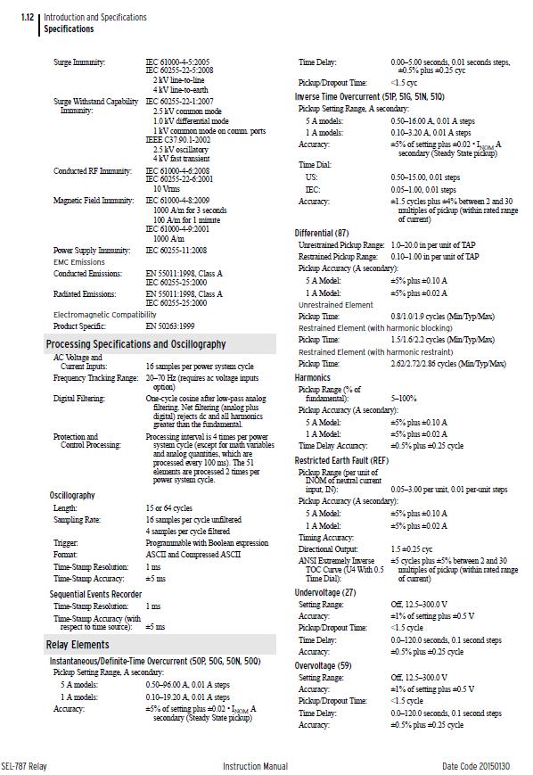
152 134
153 135
154 14.4 Appendix D Overcurrent protection element simulation results Ascelerator human machine interface 136

155 Relay front panel indication 137
156 Event summary verifying operation 138
157 Event Oscillograph 139

158 14.5 Appendix E Negative Sequence element simulation results Relay front panel indication 140
159 Ascelerator Human machine Interface 141
160 Event summary verifying operation 142
161 Sequential Event Report 143

162 14.6 Appendix G Residual Ground (50G) element simulation results Relay front panel indication 144
163 Ascelerator human to machine interface 145
164 Event summary verifying operation 146
165 Event Oscillograph 147

166 14.7 Appendix G Unrestrained differential protection (87) element simulation results Relay front panel indication 148

167 Ascelerator human to machine interface 149
ENOSERV 2014 Relay & Protection Training Conference Course Descriptions
 ENOSERV 2014 Relay & Protection Training Conference Course Descriptions Day 1 Generation Protection/Motor Bus Transfer Generator Protection: 4 hours This session highlights MV generator protection and
Modern transformer relays include a comprehensive set of protective elements to protect transformers from faults and abnormal operating conditions
 1 Transmission transformers are important links in the bulk power system. They allow transfer of power from generation centers, up to the high-voltage grid, and to bulk electric substations for distribution
Transformer Protection Principles
 Transformer Protection Principles 1. Introduction Transformers are a critical and expensive component of the power system. Due to the long lead time for repair of and replacement of transformers, a major
System Protection and Control Subcommittee
 Power Plant and Transmission System Protection Coordination Reverse Power (32), Negative Sequence Current (46), Inadvertent Energizing (50/27), Stator Ground Fault (59GN/27TH), Generator Differential (87G),
Protection of a 138/34.5 kv transformer using SEL relay
 Scholars' Mine Masters Theses Student Theses and Dissertations Fall 2016 Protection of a 138/34.5 kv transformer using SEL 387-6 relay Aamani Lakkaraju Follow this and additional works at: http://scholarsmine.mst.edu/masters_theses
Power systems Protection course
 Al-Balqa Applied University Power systems Protection course Department of Electrical Energy Engineering 1 Part 5 Relays 2 3 Relay Is a device which receive a signal from the power system thought CT and
Overcurrent Elements
 Exercise Objectives Hands-On Relay Testing Session Overcurrent Elements After completing this exercise, you should be able to do the following: Identify overcurrent element settings. Determine effective
Detecting and Managing Geomagnetically Induced Currents With Relays
 Detecting and Managing Geomagnetically Induced Currents With Relays Copyright SEL 2013 Transformer Relay Connections Voltage Current Control RTDs Transformer Protective Relay Measures differential current
ENHANCING THE PERFORMANCE OF DISTANCE PROTECTION RELAYS UNDER PRACTICAL OPERATING CONDITIONS
 ENHANCING THE PERFORMANCE OF DISTANCE PROTECTION RELAYS UNDER PRACTICAL OPERATING CONDITIONS by Kerrylynn Rochelle Pillay Submitted in fulfilment of the academic requirements for the Master of Science
NOVEL PROTECTION SYSTEMS FOR ARC FURNACE TRANSFORMERS
 NOVEL PROTECTION SYSTEMS FOR ARC FURNACE TRANSFORMERS Ljubomir KOJOVIC Cooper Power Systems - U.S.A. Lkojovic@cooperpower.com INTRODUCTION In steel facilities that use Electric Arc Furnaces (EAFs) to manufacture
Electrical Protection System Design and Operation
 ELEC9713 Industrial and Commercial Power Systems Electrical Protection System Design and Operation 1. Function of Electrical Protection Systems The three primary aims of overcurrent electrical protection
SECTION LOW VOLTAGE ACTIVE HARMONIC FILTER SYSTEM NEMA 1 ENCLOSED
 SECTION 16280 LOW VOLTAGE ACTIVE HARMONIC FILTER SYSTEM NEMA 1 ENCLOSED PART 1 - GENERAL 1.1 SUMMARY This specification defines the requirements for active harmonic filter systems in order to meet IEEE-519-2014
Catastrophic Relay Misoperations and Successful Relay Operation
 Catastrophic Relay Misoperations and Successful Relay Operation Steve Turner (Beckwith Electric Co., Inc.) Introduction This paper provides detailed technical analysis of several catastrophic relay misoperations
PROTECTION of electricity distribution networks
 PROTECTION of electricity distribution networks Juan M. Gers and Edward J. Holmes The Institution of Electrical Engineers Contents Preface and acknowledgments x 1 Introduction 1 1.1 Basic principles of
Protection of Electrical Networks. Christophe Prévé
 Protection of Electrical Networks Christophe Prévé This Page Intentionally Left Blank Protection of Electrical Networks This Page Intentionally Left Blank Protection of Electrical Networks Christophe Prévé
Improving Transformer Protection
 Omaha, NB October 12, 2017 Improving Transformer Protection Wayne Hartmann VP, Customer Excellence Senior Member, IEEE Wayne Hartmann Senior VP, Customer Excellence Speaker Bio whartmann@beckwithelectric.com
NERC Protection Coordination Webinar Series July 15, Jon Gardell
 Power Plant and Transmission System Protection Coordination Reverse Power (32), Negative Sequence Current (46), Inadvertent Energizing (50/27), Stator Ground Fault (59GN/27TH), Generator Differential (87G),
Stabilized Differential Relay SPAD 346. Product Guide
 Issued: July 1998 Status: Updated Version: D/21.03.2006 Data subject to change without notice Features Integrated three-phase differential relay, three-phase overcurrent relay and multiconfigurable earth-fault
1 INTRODUCTION 1.1 PRODUCT DESCRIPTION
 GEK-00682D INTRODUCTION INTRODUCTION. PRODUCT DESCRIPTION The MDP Digital Time Overcurrent Relay is a digital, microprocessor based, nondirectional overcurrent relay that protects against phase-to-phase
Busbars and lines are important elements
 CHAPTER CHAPTER 23 Protection of Busbars and Lines 23.1 Busbar Protection 23.2 Protection of Lines 23.3 Time-Graded Overcurrent Protection 23.4 Differential Pilot-Wire Protection 23.5 Distance Protection
Improving High Voltage Power System Performance. Using Arc Suppression Coils
 Improving High Voltage Power System Performance Using Arc Suppression Coils by Robert Thomas Burgess B Com MIEAust CPEng RPEQ A Dissertation Submitted in Fulfilment of the Requirements for the degree of
Impact of transient saturation of Current Transformer during cyclic operations Analysis and Diagnosis
 1 Impact of transient saturation of Current Transformer during cyclic operations Analysis and Diagnosis BK Pandey, DGM(OS-Elect) Venkateswara Rao Bitra, Manager (EMD Simhadri) 1.0 Introduction: Current
ARC FLASH HAZARD ANALYSIS AND MITIGATION
 ARC FLASH HAZARD ANALYSIS AND MITIGATION J.C. Das IEEE PRESS SERIES 0N POWER ENGINEERING Mohamed E. El-Hawary, Series Editor IEEE IEEE PRESS WILEY A JOHN WILEY & SONS, INC., PUBLICATION CONTENTS Foreword
Transformer Protection
 Transformer Protection Transformer Protection Outline Fuses Protection Example Overcurrent Protection Differential Relaying Current Matching Phase Shift Compensation Tap Changing Under Load Magnetizing
T/3000 T/3000. Substation Maintenance and Commissioning Test Equipment
 T/3000 Substation Maintenance and Commissioning Test Equipment MULTI FUNCTION SYSTEM FOR TESTING SUBSTATION EQUIPMENT SUCH AS: CURRENT, VOLTAGE AND POWER TRANSFORMERS, ALL TYPE OF PROTECTION RELAYS, ENERGY
Transformer Protection
 Transformer Protection Nature of transformer faults TXs, being static, totally enclosed and oil immersed develop faults only rarely but consequences large. Three main classes of faults. 1) Faults in Auxiliary
Back to the Basics Current Transformer (CT) Testing
 Testing") Back to the Basics Current Transformer (CT) Testing As test equipment becomes more sophisticated with better features and accuracy, we risk turning our field personnel into test set operators instead of
Back to the Basics Current Transformer (CT) Testing As test equipment becomes more sophisticated with better features and accuracy, we risk turning our field personnel into test set operators instead of
www. ElectricalPartManuals. com Transformer Differential Relay MD32T Transformer Differential Relay
 Transformer Differential Relay The MD3T Transformer Differential Relay is a member of Cooper Power Systems Edison line of microprocessor based protective relays. The MD3T relay offers the following functions:
PD300. Transformer, generator and motor protection Data sheet
 PD300 Transformer, generator and motor protection Data sheet DSE_PD300_eng_AO No part of this publication may be reproduced by whatever means without the prior written permission of Ingeteam T&D. One of
g GE POWER MANAGEMENT
 745 FREQUENTLY ASKED QUESTIONS 1 I get a communication error with the relay when I try to store a setpoint. This error can occur for several different reasons. First of all, verify that the address is
OVERCURRENT PROTECTION RELAY GRD110
 INSTRUCTION MANUAL OVERCURRENT PROTECTION RELAY GRD110 TOSHIBA Corporation 2002 All Rights Reserved. ( Ver. 3.1) Safety Precautions Before using this product, please read this chapter carefully. 1 This
Protection Basics Presented by John S. Levine, P.E. Levine Lectronics and Lectric, Inc GE Consumer & Industrial Multilin
 Protection Basics Presented by John S. Levine, P.E. Levine Lectronics and Lectric, Inc. 770 565-1556 John@L-3.com 1 Protection Fundamentals By John Levine 2 Introductions Tools Outline Enervista Launchpad
Bruce L. Graves /01/$ IEEE. IEEE Industry Applications Magazine PhotoDisc, Inc.
 Bruce L. Graves A Defining a Power System A power system is an assembly of generators, transformers, power lines, fuses, circuit breakers, protective devices, cables, and associated apparatus used to generate
Sequence Networks p. 26 Sequence Network Connections and Voltages p. 27 Network Connections for Fault and General Unbalances p. 28 Sequence Network
 Preface p. iii Introduction and General Philosophies p. 1 Introduction p. 1 Classification of Relays p. 1 Analog/Digital/Numerical p. 2 Protective Relaying Systems and Their Design p. 2 Design Criteria
Microgrid Protection Student Laboratory
 Microgrid Protection Student Laboratory Ian Hellman-Wylie and Joey Navarro Senior Project California Polytechnic State University San Luis Obispo 2017 Abstract To better prepare students for careers in
2015 Relay School Bus Protection Mike Kockott March, 2015
 2015 Relay School Bus Protection Mike Kockott March, 2015 History of Bus Protection Circulating current differential (1900s) High impedance differential (1940s) Percentage restrained differential (1960s)
SHORT CIRCUIT ANALYSIS OF 220/132 KV SUBSTATION BY USING ETAP
 SHORT CIRCUIT ANALYSIS OF 220/132 KV SUBSTATION BY USING ETAP Kiran V. Natkar 1, Naveen Kumar 2 1 Student, M.E., Electrical Power System, MSS CET/ Dr. B.A.M. University, (India) 2 Electrical Power System,
SPAD 346 C Stabilized differential relay
 SPAD 346 C Stabilized differential relay Stabilized Differential Relay Type SPAD 346 C Features Integrated three-phase differential relay, three-phase overcurrent relay and multiconfigurable earth-fault
MONITORING OF DISTRIBUTION TRANSFORMER PARAMETERS USING PLC
 MONITORING OF DISTRIBUTION TRANSFORMER PARAMETERS USING PLC Shubhangi Landge¹, Snehal Waydande², Sanjay Sangale³, Somesh Gaikwad⁴ ¹Assistant Professor, Dept. Of Electrical Engineering, AISSMS IOIT College,
Relay Types and Applications Dr. Sasidharan Sreedharan
 O&M of Protection System and Relay Coordination Relay Types and Applications Dr. Sasidharan Sreedharan www.sasidharan.webs.com Detailed Schedule 2 SIMPLE RELAY Magnitude Rate of Change Phase Angle Direction
NERC Protection Coordination Webinar Series June 9, Phil Tatro Jon Gardell
 Power Plant and Transmission System Protection Coordination GSU Phase Overcurrent (51T), GSU Ground Overcurrent (51TG), and Breaker Failure (50BF) Protection NERC Protection Coordination Webinar Series
ATP modeling of internal transformer faults for relay performance testing
 Michigan Technological University Digital Commons @ Michigan Tech Dissertations, Master's Theses and Master's Reports - Open Dissertations, Master's Theses and Master's Reports 2011 ATP modeling of internal
MVCT. Megger VT & CT Analyzer. MVCT Megger VT & CT Analyzer
 MVCT Ability to test both VT and CT Easy to use one-button automated test plans Industry leading test duration using patented simultaneous tap measurements Smallest and lightest unit on the market CT Kneepoints
Distance Relay Response to Transformer Energization: Problems and Solutions
 1 Distance Relay Response to Transformer Energization: Problems and Solutions Joe Mooney, P.E. and Satish Samineni, Schweitzer Engineering Laboratories Abstract Modern distance relays use various filtering
Problems connected with Commissioning of Power Transformers
 Problems connected with Commissioning of Power Transformers ABSTRACT P Ramachandran ABB India Ltd, Vadodara, India While commissioning large Power Transformers, certain abnormal phenomena were noticed.
Protecting power transformers from common adverse conditions
 Protecting power transformers from common adverse conditions by Ali Kazemi, and Casper Labuschagne, Schweitzer Engineering Laboratories Power transformers of various size and configuration are used throughout
Design and Development of Protective Circuit against Voltage Disturbances
 Design and Development of Protective Circuit against Voltage Disturbances Shashidhar Kasthala 1, Krishnapriya 2, Rajitha Saka 3 1,2 Facultyof ECE, Indian Naval Academy, Ezhimala, Kerala 3 Assistant Professor
McPherson Voltage Regulators 4501 NW 27 Ave Miami FL
 McPherson Voltage Regulators 4501 NW 27 Ave Miami FL 33142 305-634-1511 To avoid of possible personal injury or equipment damage read and understand this manual before installation. (A.V.R) 208 / 380 /
1960 Research Drive, Suite 100, Troy, Michigan with. REVISION: December 10, 2007 (Supersedes previous versions) Prepared by:
 Prepared by:") ENGINEERING SERVICES 1960 Research Drive, Suite 100, Troy, Michigan 48083 ARC FLASH REDUCTION with SEPAM RELAY ZONE SELECTIVE INTERLOCKING REVISION: December 10, 2007 (Supersedes previous versions) Prepared
ENGINEERING SERVICES 1960 Research Drive, Suite 100, Troy, Michigan 48083 ARC FLASH REDUCTION with SEPAM RELAY ZONE SELECTIVE INTERLOCKING REVISION: December 10, 2007 (Supersedes previous versions) Prepared
OPEN-PHASE DETECTION TECHNIQUES FOR CRITICAL STANDBY SUPPLIES
 OPEN-PHASE DETECTION TECHNIQUES FOR CRITICAL STANDBY SUPPLIES U AJMAL, GE Grid Solutions UK Ltd, usman.ajmal@ge.com S SUBRAMANIAN, GE Grid Solutions UK Ltd, sankara.subramanian@ge.com H Ha GE Grid Solutions
Transformer protection IED RET 670
 Gunnar Stranne Transformer protection IED RET 670 Santiago Septiembre 5, 2006 1 Transformer protection IED RET670 2 Introduction features and applications Differential protection functions Restricted Earth
TECHNICAL BULLETIN 004a Ferroresonance
 May 29, 2002 TECHNICAL BULLETIN 004a Ferroresonance Abstract - This paper describes the phenomenon of ferroresonance, the conditions under which it may appear in electric power systems, and some techniques
Overcurrent and Overload Protection of AC Machines and Power Transformers
 Exercise 2 Overcurrent and Overload Protection of AC Machines and Power Transformers EXERCISE OBJECTIVE When you have completed this exercise, you will understand the relationship between the power rating
Automatic Load Sharing of Transformers using Microcontroller
 Automatic Load Sharing of Transformers using Microcontroller Akhil Krishnan V 1, Arun P S 1, D Yathishan 1, Jomice Thomas 1, D K Narayanan 2 U.G. Students, Department of Electrical and Electronics Engineering,
Numbering System for Protective Devices, Control and Indication Devices for Power Systems
 Appendix C Numbering System for Protective Devices, Control and Indication Devices for Power Systems C.1 APPLICATION OF PROTECTIVE RELAYS, CONTROL AND ALARM DEVICES FOR POWER SYSTEM CIRCUITS The requirements
Power System Protection. Dr. Lionel R. Orama Exclusa, PE Week 3
 Power System Protection Dr. Lionel R. Orama Exclusa, PE Week 3 Operating Principles: Electromagnetic Attraction Relays Readings-Mason Chapters & 3 Operating quantities Electromagnetic attraction Response
COPYRIGHTED MATERIAL. Index
 Index Note: Bold italic type refers to entries in the Table of Contents, refers to a Standard Title and Reference number and # refers to a specific standard within the buff book 91, 40, 48* 100, 8, 22*,
SEL-311C TRANSMISSION PROTECTION SYSTEM
 SEL-3C TRANSMISSION PROTECTION SYSTEM ADVANCED TRANSMISSION LINE PROTECTION, AUTOMATION, AND CONTROL Bus ANSI NUMBERS/ACRONYMS AND FUNCTIONS 52 3 3 2 P G 8 O U 27 68 50BF 67 P G Q 50 P G Q 59 P G Q 5 P
Industrial Electrician Level 3
 Industrial Electrician Level 3 Industrial Electrician Unit: C1 Industrial Electrical Code I Level: Three Duration: 77 hours Theory: Practical: 77 hours 0 hours Overview: This unit is designed to provide
Advanced Test Equipment Rentals ATEC (2832)
") Established 1981 Advanced Test Equipment Rentals www.atecorp.com 800-404-ATEC (2832) The toolbox for substation 3-phase testing Three currents and four voltages Stand-alone functionality Rugged and reliable
Established 1981 Advanced Test Equipment Rentals www.atecorp.com 800-404-ATEC (2832) The toolbox for substation 3-phase testing Three currents and four voltages Stand-alone functionality Rugged and reliable
 Power Station Electrical Protection A 2 B 2 C 2 Neutral C.T E M L } a 2 b 2 c 2 M M M CT Restricted E/F Relay L L L TO TRIP CIRCUIT Contents 1 The Need for Protection 2 1.1 Types of Faults............................
3 Pole high impedance differential relay 7VH83
 Fig 1. High impedance differential protection relay 7VH83 Features l Integral CT shorting relay. l Robust solid state design. l Inrush stabilisation through filtering. l Fast operating time. l LED indicator.
REDUCTION OF TRANSFORMER INRUSH CURRENT BY CONTROLLED SWITCHING METHOD. Trivandrum
 International Journal of Scientific & Engineering Research, Volume 7, Issue 4, April-216 628 REDUCTION OF TRANSFORMER INRUSH CURRENT BY CONTROLLED SWITCHING METHOD Abhilash.G.R Smitha K.S Vocational Teacher
Unit Protection Differential Relays
 Unit Protection PROF. SHAHRAM MONTASER KOUHSARI Current, pu Current, pu Protection Relays - BASICS Note on CT polarity dots Through-current: must not operate Internal fault: must operate The CT currents
Application for A Sub-harmonic Protection Relay. ERLPhase Power Technologies
 Application for A Sub-harmonic Protection Relay ERLPhase Power Technologies 1 Outline Introduction System Event at Xcel Energy Event Analysis Microprocessor based relay hardware architecture Sub harmonic
Addendum to Instructions for Installation, Operation and Maintenance of Digitrip 3000 Protective Relays
 Dual-Source Power Supply Addendum to I.B. 17555 Addendum to Instructions for Installation, Operation and Maintenance of Digitrip 3000 Protective Relays Table of Contents Page 1.0 Introduction...1 2.0 General
BE1-67N GROUND DIRECTIONAL OVERCURRENT RELAY FEATURES ADDITIONAL INFORMATION. FUNCTIONS AND FEATURES Pages 2-4. APPLICATIONS Page 2
 BE1-67N GROUND DIRECTIONAL OVERCURRENT RELAY The BE1-67N Ground Directional Overcurrent Relay provides ground fault protection for transmission and distribution lines by sensing the direction and magnitude
N. TEST TEST DESCRIPTION
 Multi function system for testing substation equipment such as: current, voltage and power transformers, all type of protection relays, energy meters and transducers Primary injection testing capabilities
Universal Protection System for Ac Industrial Motors
 Universal Protection System for Ac Industrial Motors Mr. Ibrahim Rawat 1, Mr. Saurabh Patel 2, Mr. Akshil Chauhan 3, Mr. Nisargkumar Parmar 4, Mr. Sunil Malival 5 1234 B.E Students, ITM Universe, Vadodara
Power System Protection Manual
 Power System Protection Manual Note: This manual is in the formative stage. Not all the experiments have been covered here though they are operational in the laboratory. When the full manual is ready,
APPLICATION: The heart of the system is a DSR 100 Digital Static Regulator used in conjunction with standard SCR based rectifier bridges.
 APPLICATION: Basler Electric offers a New Line of digitally controlled brush (static) or brushless excitation systems designed for use with existing Hydro, Gas as well as Diesel driven generators requiring
Generator Advanced Concepts
 Generator Advanced Concepts Common Topics, The Practical Side Machine Output Voltage Equation Pitch Harmonics Circulating Currents when Paralleling Reactances and Time Constants Three Generator Curves
A1000 ALPHA and A1200 ALPHA Meter Installation Instructions. General. Installation. For A1000 ALPHA Type R, A1000 ALPHA Type C, and A1200 ALPHA Meters
 January 003 IL4-401B A1000 ALPHA and A100 ALPHA Meter Installation Instructions For A1000 ALPHA Type R, A1000 ALPHA Type C, and A100 ALPHA Meters General This leaflet contains general installation instructions
Distance Element Performance Under Conditions of CT Saturation
 Distance Element Performance Under Conditions of CT Saturation Joe Mooney Schweitzer Engineering Laboratories, Inc. Published in the proceedings of the th Annual Georgia Tech Fault and Disturbance Analysis
GRAAD 12 NATIONAL SENIOR CERTIFICATE GRADE 12
 GRAAD 12 NATIONAL SENIOR CERTIFICATE GRADE 12 ELECTRICAL TECHNOLOGY EXEMPLAR 2014 MEMORANDUM MARKS: 200 This memorandum consists of 13 pages. Electrical Technology 2 DBE/2014 INSTRUCTIONS TO THE MARKERS
INTER PLANT STANDARD STEEL INDUSTRY VARIABLE VOLTAGE VARIABLE FREQUENCY SYSTEM (V.V.V.F.) V/F, VECTOR CONTROL / TORQUE CONTROL
 V/F, VECTOR CONTROL / TORQUE CONTROL") INTER PLANT STANDARD STEEL INDUSTRY VARIABLE VOLTAGE VARIABLE FREQUENCY SYSTEM (V.V.V.F.) V/F, VECTOR CONTROL / TORQUE CONTROL IPSS: 1-10-035-06 IPSS Corresponding IS does not exist 0. FOREWORD 0.1 This
INTER PLANT STANDARD STEEL INDUSTRY VARIABLE VOLTAGE VARIABLE FREQUENCY SYSTEM (V.V.V.F.) V/F, VECTOR CONTROL / TORQUE CONTROL IPSS: 1-10-035-06 IPSS Corresponding IS does not exist 0. FOREWORD 0.1 This
ASHIDA Numerical OC/EF Protection Relay
 ASHIDA Numerical OC/EF Protection Relay Features: 4 Element (3 Phase + EF) over current IDMT with instant trip. Back - lit LCD display for settings. Display of fault current. / Load current. Selection
10. DISTURBANCE VOLTAGE WITHSTAND CAPABILITY
 9. INTRODUCTION Control Cabling The protection and control equipment in power plants and substations is influenced by various of environmental conditions. One of the most significant environmental factor
Specialists in HV and MV test and diagnostics. Testing in Substations
 Specialists in HV and MV test and diagnostics Testing in Substations Testing in Substations Testing in Substations At 4fores we specialize in the diagnosis and measurement of all types of existing technologies
CONTENTS. 1. Introduction Generating Stations 9 40
 CONTENTS 1. Introduction 1 8 Importance of Electrical Energy Generation of Electrical Energy Sources of Energy Comparison of Energy Sources Units of Energy Relationship among Energy Units Efficiency Calorific
Hands On Relay School Open Lecture Transformer Differential Protection Scott Cooper
 Hands On Relay School Open Lecture Transformer Differential Protection Scott Cooper Transformer Differential Protection ntroduction: Transformer differential protection schemes are ubiquitous to almost
EE Lecture 14 Wed Feb 8, 2017
 EE 5223 - Lecture 14 Wed Feb 8, 2017 Ongoing List of Topics: URL: http://www.ece.mtu.edu/faculty/bamork/ee5223/index.htm Labs - EE5224 Lab 3 - begins on Tues Feb 14th Term Project - details posted. Limit
A NEW DIRECTIONAL OVER CURRENT RELAYING SCHEME FOR DISTRIBUTION FEEDERS IN THE PRESENCE OF DG
 A NEW DIRECTIONAL OVER CURRENT RELAYING SCHEME FOR DISTRIBUTION FEEDERS IN THE PRESENCE OF DG CHAPTER 3 3.1 INTRODUCTION In plain radial feeders, the non-directional relays are used as they operate when
Burdens & Current Transformer Requirements of MiCOM Relays. Application Notes B&CT/EN AP/B11. www. ElectricalPartManuals. com
 Burdens & Current Transformer Requirements of MiCOM Relays Application Notes B&CT/EN AP/B11 Application Notes B&CT/EN AP/B11 Burdens & CT Req. of MiCOM Relays Page 1/46 CONTENTS 1. ABBREVIATIONS & SYMBOLS
Preface...x Chapter 1 Electrical Fundamentals
 Preface...x Chapter 1 Electrical Fundamentals Unit 1 Matter...3 Introduction...3 1.1 Matter...3 1.2 Atomic Theory...3 1.3 Law of Electrical Charges...4 1.4 Law of Atomic Charges...5 Negative Atomic Charge...5
Unit 3 Magnetism...21 Introduction The Natural Magnet Magnetic Polarities Magnetic Compass...21
 Chapter 1 Electrical Fundamentals Unit 1 Matter...3 Introduction...3 1.1 Matter...3 1.2 Atomic Theory...3 1.3 Law of Electrical Charges...4 1.4 Law of Atomic Charges...4 Negative Atomic Charge...4 Positive
Associate In Applied Science In Electronics Engineering Technology Expiration Date:
 PROGRESS RECORD Study your lessons in the order listed below. Associate In Applied Science In Electronics Engineering Technology Expiration Date: 1 2330A Current and Voltage 2 2330B Controlling Current
GE Power Management. Digital Microprocessor-based Non-directional Overcurrent Relays MIC series 1000 Instructions GEK 98840C
 GE Power Management Digital Microprocessor-based Non-directional Overcurrent Relays MIC series 1000 Instructions GEK 98840C 7$%/(2)&217(176 1. DESCRIPTION...2 2. APPLICATION...6 3. CHARACTERISTICS...7
Relion 605 series. Self-Powered Feeder Protection REJ603 Application manual
 Relion 605 series Relion 605 series Relion 605 series Self-Powered Feeder Protection REJ603 Application manual Document ID: 1MDU07206-YN 6 2 4 This document and parts thereof must not be reproduced or
Transformer Differential Protection Lab
 Montana Tech Library Digital Commons @ Montana Tech Proceedings of the Annual Montana Tech Electrical and General Engineering Symposium Student Scholarship 2016 Transformer Differential Protection Lab
Power System Protection Lecture Notes
 Power System Protection Lecture Notes Mohammed T. Lazim Alzuhairi Professor of Electrical and Electronics Engineering Electrical Engineering Department Philadelphia University, Jordan 1 Power System protection
Power System Protection Part VII Dr.Prof.Mohammed Tawfeeq Al-Zuhairi. Differential Protection (Unit protection)
") Differential Protection (Unit protection) Differential Protection Differential protection is the best technique in protection. In this type of protection the electrical quantities entering and leaving
Differential Protection (Unit protection) Differential Protection Differential protection is the best technique in protection. In this type of protection the electrical quantities entering and leaving
Modular range of digital protection relays
 S e p a m s e r i e s 2 0, 4 0, 8 0 Modular range of digital protection relays Fast Dependable Simple Fast response Maximum dependability Your electrical equipment is under control. With Sepam protection
Keywords: Transformer, differential protection, fuzzy rules, inrush current. 1. Conventional Protection Scheme For Power Transformer
 Vol. 3 Issue 2, February-2014, pp: (69-75), Impact Factor: 1.252, Available online at: www.erpublications.com Modeling and Simulation of Modern Digital Differential Protection Scheme of Power Transformer
Implementation Of Solid State Relays For Power System Protection
 Implementation Of Solid State Relays For Power System Protection Nidhi Verma, Kartik Gupta, Sheila Mahapatra ABSTRACT: This paper provides the implementation of solid state relays for enhancement of power
A proven distribution feeder solution with integrated protection, monitoring, and control
 SEL-35 Protection System A proven distribution feeder solution with integrated protection, monitoring, and control Achieve sensitive and secure fault detection using comprehensive protection functions.
MFAC. Grid Solutions. High Impedance Differential Relay. MFAC Types. Key Benefits. Application. Description. Imagination at work
 GE Grid Solutions MFAC High Impedance Differential Relay MFAC relays provide high speed differential protection for various types of power systems plants including generators, reactors, busbars, motors
Preventing transformer saturation in static transfer switches A Real Time Flux Control Method
 W H I T E PA P E R Preventing transformer saturation in static transfer switches A Real Time Flux Control Method TM 2 SUPERSWITCH 4 WITH REAL TIME FLUX CONTROL TM Preventing transformer saturation in static
Ferroresonance in MV Voltage Transformers: Pragmatic experimental approach towards investigation of risk and mitigating strategy
 Ferroresonance in MV Voltage Transformers: Pragmatic experimental approach towards investigation of risk and mitigating strategy W. Piasecki, M. Stosur, T. Kuczek, M. Kuniewski, R. Javora Abstract-- Evaluation
CHAPTER 7 HARDWARE IMPLEMENTATION
 168 CHAPTER 7 HARDWARE IMPLEMENTATION 7.1 OVERVIEW In the previous chapters discussed about the design and simulation of Discrete controller for ZVS Buck, Interleaved Boost, Buck-Boost, Double Frequency