Stabilized Differential Relay SPAD 346. Product Guide
|
|
|
- Nathan Richard
- 6 years ago
- Views:
Transcription
1
2
3 Issued: July 1998 Status: Updated Version: D/ Data subject to change without notice Features Integrated three-phase differential relay, three-phase overcurrent relay and multiconfigurable earth-fault relay Alarm channels activated by normally open or normally closed contact Stabilized differential relay module providing winding short-circuit and interturn fault protection for two-winding power transformers and generator-transformer units, and interwinding short-circuit protection for generators Earth-fault relay module providing protection for transformer HV and LV side according to the principle selected: stabilized differential current principle, high-impedance principle, residual current principle or neutral current principle Three-stage overcurrent module providing protection for power transformers and generators and two-stage back-up earth-fault protection Short operate time even at partial saturation of the current transformers Operation characteristic of differential relay module easily adapted for different applications Stabilized against unwanted operations at faults occurring outside the protected area and at transformer inrush currents Second harmonic restraint for prevention of unwanted relay operations at transformer inrush currents Fifth harmonic restraint for prevention of unwanted relay operations at transformer overexcitation. The fifth harmonic restraint can be aborted if the ratio of the fifth harmonic and the basic frequency component rises too high at dangerous overvoltages Wide CT ratio correction range: accurate correction through digital setting No interposing current transformers needed for the protection of two-winding power transformers: numerical vector group matching on HV and LV side Four heavy-duty output relays for circuit breaker tripping and five output relays for signalling Five programmable external control inputs intended for alarm and trip signals from gas relays, oil temperature sensors and other sensors of transformer auxiliary devices Integrated circuit-breaker failure protection with adjustable operate time Differential relay and earth-fault relay modules provided with integrated disturbance recorder functions for analog and digital signals: signals to be used for triggering selectable Sensitive phase current and phase angle displays facilitate checking of energizing circuit connections and vector group matchings High immunity to electrical and electromagnetic interference allows the relay to be used in severe environments High availability and system reliability due to continuous supervision of hardware and software Powerful software supports relay parameterization and reading of measured and recorded values and event data Member of the SPACOM product family and ABB s Distribution Automation system CE marking according to the EC directive for EMC Application The stabilized differential relay C is designed for protecting two-winding power transformers and generator-transformer units against winding short-circuit, interturn fault, earth fault and short circuit, and generators and motors against interwinding faults and pole short circuit. In addition, the relay can be used for the protection of three-winding power transformers, provided 75% of the short circuit power to the power transformer is supplied from the same direction, and for the protection of compensating chokes and short cable lines. No interposing transformers are needed for the protection of two-winding power transformers, as the relay allows the vector group matching, the elimination of the zerosequence component of the phase currents and the CT ratio corrections to be carried out numerically. 3
4 Design The feeder protection relay is provided with six energizing inputs for phase currents and inputs for residual or neutral currents. The relay is also equipped with nine output relays for CB control, signalling, etc. The differential relay consists of three protection relay modules, i.e. a differential relay module, an earth-fault relay module and a combined overcurrent and earth-fault relay module. The modules are withdrawable as are the power supply module and the I/O relay module located behind the system front panel. Differential relay module SPCD 3D53 The differential relay module includes three protection units, i.e. a stabilized differential current unit, an instantaneous differential current unit and a circuit-breaker failure protection unit. In addition, the module contains a disturbance recorder unit. The stabilized differential current unit constitutes the main differential protection. The unit is provided with second and third harmonic restraint, selectable transformer vector group, zero-sequence current elimination, numerical correction of CT ratios and flexible configuration of tripping, blocking and control signals. The instantaneous, non-stabilized differential current unit functions as an ultra-fast protection unit with an operate time less than 30 ms at heavy faults. The circuit-breaker failure protection unit is activated by the main trip signal of the other protection units and it provides a second trip signal to be routed to a back-up circuit breaker if the main CB fails to operate. The differential relay module also incorporates a digital disturbance recorder module. The module continuously monitors the object protected and stores pre- and post-fault network information, which can be used for post-fault analysis. Earth-fault relay module SPCD 2D55 The earth-fault relay module measures the neutral current and/or residual current on both sides of the object protected. The earth-fault protection can be implemented by four different principles, i.e. the high-impedance principle, the numerical stabilized differential current principle, the residual overcurrent principle or the neutral overcurrent principle. Both sides of the object can be protected independent of each other, which means that the protection principle on one side does not have to be the same as that of the other side. The circuit-breaker failure protection unit is activated by the main trip signal of the protection units and it provides a second trip signal to be routed to a back-up circuit breaker if the main CB fails to operate. The earth-fault relay module also incorporates a digital disturbance recorder module. The module continuously monitors the object protected and stores pre- and post-fault network information, which can be used for post-fault analysis. Combined overcurrent and earth-fault relay module SPCJ 4D28 The combined overcurrent and earth-fault module includes four protection units, i.e. an overcurrent unit, an earth-fault unit, a phase discontinuity unit and a circuit-breaker failure protection unit. The three-phase overcurrent unit comprises three overcurrent stages, i.e. a low-set stage I>, a high-set stage I>> and a super high-set stage I>>>. The low-set stage can be given definite time characteristic or inverse time characteristic while the high-set stage and the super high-set stage have a definite time characteristic. The non-directional earth-fault unit comprises two protection stages, i.e. a low-set stage I 0 > and a high-set stage I 0 >>. The lowset stage can be given definite time characteristic or inverse time characteristic while the high-set stage has a definite time characteristic. The phase discontinuity protection unit measures the phase unbalance and has a definite time characteristic. The circuit-breaker failure protection unit is activated by the main trip signal of the protection units and it provides a second trip signal to be routed to a back-up circuit breaker if the main CB fails to operate. 4
5 Design (cont d) Data communication The feeder protection relay is equipped with a serial communication port on the rear panel. The serial port is used for connecting the relay to the SPA bus via an optional bus connection module. Two bus connection module types are available: SPA-ZC 17 and SPA- ZC 21. The former can be powered from the host relay and from a separate power source at the same time, while the latter is powered from the host relay via the D-type connector. Output relays and circuit breaker control The feeder protection relay is provided with nine output auxiliary relays, four of which are heavy-duty output relays for the direct control of the circuit breaker. Single-pole or doublepole circuit breaker control can be used. One of the five signalling relays is permanently allocated for the self-supervision system. The function of the other four relays can be defined by the user. Self-supervision The relay incorporates a sophisticated selfsupervision system with auto-diagnosis, which increases the availability of the relay and the reliability of the system. The selfsupervision system continuously monitors the hardware and the software of the relay. The system also supervises the operation of the auxiliary supply module and the voltages generated by the module. Auxiliary supply voltage The auxiliary supply of the relay is obtained from an internal plug-in type power supply module. Two auxiliary power module versions are available: type SPGU 240A1 for the supply voltage range V ac/dc and type SPGU 48B2 for the supply voltage range V dc. The power supply module forms the internal voltages required by the protection relay and the I/O module. 5
6 Technical data Table 1: Energizing inputs Terminals X0/1-3, 4-6, 7-9, X0/13-15, 16-18, X0/19-21, X0/37-39 X0/1-2, 4-5, 7-8, X0/13-14, 16-17, X0/19-20, 25-26, X0/37-38 Rated current I n 1 A 5 A Thermal current continuously 4 A 20 A withstand for 10 s 25 A 100 A for 1 s 100 A 500 A Dynamic current Half-wave value 250 A 1250 A withstand Input impedance <100 mω <20 mω Rated frequency f n, according to order 50 Hz or 60 Hz Table 2: Output contact ratings Type of contact Tripping Signalling Terminals X1/ X1/ X2/3-4, 5-6 X2/7-8, 9-10 X2/ X2/14-15 X2/ Rated voltage 250 V ac/dc Thermal withstand Carry continuously 5 A 5 A capability Make and carry for 0.5 s 30 A 10 A Make and carry for 3 s 15 A 8 A Breaking capacity for dc, 220 V dc 1 A 0.15 A when the signal circuit 110 V dc 3 A 0.25 A time constant L/R 40 ms, at the signalling voltage levels 48 V dc 5 A 1 A Table 3: External control inputs Terminals X1/1-2, 3-4, 5-6, 7-8, 9-10 Control voltage Operative range V dc or V ac Current drain of activated control input 2 20 ma Active state of input Input active when energized Input active when non-energized Table 4: Auxiliary supply modules Terminal numbers X2/1-2 Type of module Rated voltages U n SPGU 240A1 110/120/230/240 V ac 110/125/220 V dc SPGU 48B2 24/48/60 V ac Operative range SPGU 240A V ac/dc SPGU 48B V dc Power consumption under quiescent ~10 W conditions under operating conditions ~15 W 6
7 Technical data (cont d) Table 5: Stabilized differential relay module SPCD 3D53 Selectable rated frequency f n CT ratio correction range on power transformer HV side I 1 /I n CT ratio correction range on power transformer LV side I 2 /I n Stabilized differential current stage 3 I> Basic start ratio P/I n Starting ratio setting S Second turning point I 2tp /I n of characteristic curve Harmonics blocking ratio I d2f /I d1f Harmonics blocking ratio I d5f /I d1f Harmonics deblocking ratio I d5f /I d1f Operate time (including heavy-duty output relays at currents operate value Operation accuracy Instantaneous differential current stage 3 I>> at currents above 4 operate value 16 2 / 3 60 Hz 10 50% % 10 50% 10 50% <50 ms <45 ms ±4% of set value or ±2% I n Start ratio I d /I n >> 5 30 Operate time (including heavy-duty output relays at ratios in the range of <35 ms I d /I n >> at ratios above 2.6 <30 ms I d /I n >> Operation accuracy ±4% of set value of 2% I n Circuit-breaker failure protection Operate time s Integrated disturbance recorder Recording length 38 cycles Recording memory capacity 1 recording = 38 cycles Sampling frequency 40 samples/cycle Signals to be recorded 6 analog signals 11 digital signals Triggering when the selected digital is activated signal when the selected digital resets signal Length of recording preceding triggering 0 38 cycles Table 6: Earth-fault relay module SPCD 2D55 Selectable rated frequency f n Stabilized differential relay principle Basic start ratio on HV side P 1 /I n Operate time on HV side t 01 > Basic start ratio on LV side P 2 /I n Operate time setting on LV side t 02 > Correction range of HV side neutral connection CT ratio I 01 /I n Setting of minimum ratio of HV side neutral current and residual current of phase currents I 01 / I 1 Correction range of LV side neutral connection CT ratio I 02 /I n Setting of minimum ratio of LV side neutral current and residual current of phase currents I 02 / I 2 Second harmonics restraint ratio I 2f /I 1f of HV side neutral current I 01 Second harmonics restraint ratio I 2f /I 1f of LV side neutral current I 02 Correction range of HV side phase CT ratio I 1 /I n Correction range of HV side phase CT ratio I 2 /I n Operate time at minimum delay (including heavy-duty output relays) 16 2 / 3 60 Hz s s 0 20% 0 20% 10 50% 10 50% ms 7
8 Technical data (cont d) Table 6: Earth-fault relay module SPCD 2D55 Operation accuracy Principle based on calculated residual current Basic start ratio P 1 /I n on HV side Operate time t 01 > on HV side Basic start ratio P 2 /I n on LV side Operate time setting t 02 > on LV side Correction range of HV side phase CT ratio I 1 /I n Correction range of HV side phase CT ratio I 2 /I n Operate time at minimum delay (including heavy-duty output relays) Operation accuracy Principle based on measured residual current or neutral current Basic start ratio P 1 /I n on HV side Operate time t 01 > on HV side Basic start ratio P 2 /I n on LV side Operate time setting t 02 > on LV side Correction range of HV side neutral connection CT ratio I 01 /I n Correction range of LV side neutral connection CT ratio I 02 /I n Second harmonics restraint ratio I 2f /I 1f of HV side neutral current I 01 Second harmonics restraint ratio I 2f /I 1f of LV side neutral current I 02 Operate time at minimum delay (including heavy-duty output relays) Operation accuracy Restricted earth-fault principle (high-impedance type earth-fault protection) Basic start ratio P 1 /I n on HV side Operate time t 01 > on HV side Basic start ratio P 2 /I n on LV side Operate time setting t 02 > on LV side Correction range of HV side neutral connection CT ratio I 01 /I n Correction range of LV side neutral connection CT ratio I 02 /I n Operate time at minimum delay (including heavy-duty output relays) Operation accuracy Circuit-breaker failure protection Operate time Integrated disturbance recorder Recording length Recording memory capacity Sampling frequency Signals to be recorded Triggering Length of recording preceding triggering when the selected digital signal when the selected digital signal ±4% of set value or ±2% of I n s s ms ±4% of set value or ±2% of I n s s 10 50% 10 50% ms ±4% of set value or ±2% of I n s s ms ±4% of set value or ±2% of I n s 30 cycles 1 recording = 30 cycles 40 samples/cycle 8 analog signals 12 digital signals is activated resets 0 30 cycles 8
9 Technical data (cont d) Table 7: Relay module SPCJ 4D28, overcurrent unit Features Stage I> Stage I>> Stage I>>> Start current at definite time I n I n and I n and at inverse time I n Start time, typically 70 ms 40 ms 40 ms Operate time at definite time s s s characteristic Time/current characteristic at inverse Extremely inverse time mode Very inverse Normal inverse Long-time inverse RI type inverse RXIDG type inverse Time multiplier k Reset time, typically 40 ms 40 ms 40 ms Retardation time <30 ms Reset ratio, typically 0.96 Operate time accuracy at definite time ±2% of set value or ±25 ms mode Accuracy class index E at inverse time 5 mode Operation accuracy ±3% of set value ±3% of set value ±3% of set value Table 8: Relay module SPCJ 4D28, earth-fault and phase discontinuity unit Features Stage I 0 > Stage I 0 >> Stage I> Start current I n I n and % and Start time, typically 70 ms 50 ms 150 ms Operate time at definite time s s s characteristic Time/current characteristic at inverse Extremely inverse time mode Very inverse Normal inverse Long-time inverse RI type inverse RXIDG type inverse Time multiplier k Reset time, typically 40 ms 40 ms 80 ms Retardation time <30 ms <30 ms Reset ratio, typically Operate time accuracy at definite time ±2% of set value or ±25 ms mode Accuracy class index E at inverse time 5 mode Operation accuracy ±3% of set value ±3% of set value ±1 unit ±3% of set value 9
10 Technical data (cont d) Table 9: Data communication Transmission mode Data code Data transfer rate, selectable Electrical/optical bus connection module powered from the host relay Electrical/optical bus connection module powered from the host relay or from an external power source Table 10: Tests and standards for plastic core cables for glass fibre cables for plastic core cables for glass fibre cables Fibre-optic serial bus ASCII 4800 or 9600 Bd SPA-ZC 21BB SPA-ZC 21MM SPA-ZC 17BB SPA-ZC 17MM Test voltages Dielectric test voltage (IEC ) 2 kv, 50 Hz, 1 min Interference tests Impulse test voltage (IEC ) Insulation resistance (IEC ) High frequency disturbance test (IEC ), common mode High frequency disturbance test (IEC ), differential mode 5 kv, 1.2/50 µs, 0.5 J >100 MΩ, 500 V dc 2.5 kv, 1 MHz 1.0 kv, 1 MHz Electrostatic discharge (IEC kv and IEC ), air discharge Electrostatic discharge (IEC kv and IEC ), contact discharge Fast transients (IEC and 4 kv IEC ), power supply inputs Fast transients (IEC and 2 kv IEC ), other inputs Environmental conditions Service temperature range C Long term damp heat withstand <95%, +40 C, 56 d/a (IEC ) Temperature influence 0.1%/ C Damp heat test (IEC ) 93 95%, +55 C, 6 cycles Transport and storage temperature range C (IEC ) Degree of protection by enclosure of flush IP 54 mounting relay case (IEC 60529) Weight of fully equipped relay ~6 kg 10
11 Block diagram Fig. 1 Block diagram and sample connection diagram BSPAD346 11
12 Mounting and dimensions Flush mounting ± ±1 Panel cut-out dim300 Fig. 2 Flush-mounting relay case (dimensions in mm) Semi-flush mounting a b Raising frame SPA-ZX 301 SPA-ZX 302 SPA-ZX 303 a b SFM300_1 Fig. 3 Semi-flush mounting relay case (dimensions in mm) Mounting in 19 inch cabinets and frames An ancillary mounting plate, height 4U (~177 mm), is recommended to be used when the protection relays are to be mounted in 19 inch frames or cabinets. The ancillary mounting plate type SPA-ZX 304 accommodates two size 300 relays and type SPA-ZX 305 one size 300 relay. Projecting mounting When projecting mounting is preferred, a relay case type SPA-ZX 317 is used. The relay case for projecting mounting is provided with front connectors. SPA-ZX304 SPA-ZX305 SPA-ZX201 SPA-ZX306 SPA-ZX307 SPA-ZX317 SPA-ZX318 +0,4 482,6 0 (19") ø ,5 101,6 7 +0, (4U) 304_5_6 Fig. 4 Mounting cabinets and frames as well as projecting mounting (dimensions in mm) 12
13 Ordering When ordering, please specify: Ordering information Ordering example 1. Type designation and quantity C, 5 pieces 2. Order number RS AA 3. Rated values I n =5 A, f n =50 Hz 4. Auxiliary voltage U aux =110 V dc 5. Accessories - 6. Special requirements - Order numbers Stabilized differential relay C_ C complete C1, incl. modules SPCD 3D53 and SPCD 2D55 C2, incl. modules SPCD 3D53 and SPCJ 4D28 C3, incl. module SPCD 3D53 C4, incl. modules SPCD 2D55 and SPCJ 4D28 C5, incl. module SPCD 2D55 C6, incl. module SPCJ 4D28 The last two letters of the order number indicate the rated frequency f n and the auxiliary voltage U aux of the relay as follows: RS AA, CA, DA, FA RS AA, CA, DA, FA RS AA, CA, DA, FA RS AA, CA, DA, FA RS AA, CA, DA, FA RS AA, CA, DA, FA RS AA, CA, DA, FA AA equals f n = 50 Hz and U aux = V ac/dc CA equals f n = 50 Hz and U aux = V dc DA equals f n = 60 Hz and U aux = V ac/dc FA equals f n = 60 Hz and U aux = V dc Stabilized differential relay C_ including a test adapter type RTXP18 C complete RS AA, CA, DA, FA C1, incl. modules SPCD 3D53 and RS AA, CA, DA, FA SPCD 2D55 C2, incl. modules SPCD 3D53 and RS AA, CA, DA, FA SPCJ 4D28 C3, incl. module SPCD 3D53 RS AA, CA, DA, FA C4, incl. modules SPCD 2D55 and RS AA, CA, DA, FA SPCJ 4D28 C5, incl. module SPCD 2D55 RS AA, CA, DA, FA C6, incl. module SPCJ 4D28 RS AA, CA, DA, FA The last two letters of the order number indicate the AA equals f n = 50 Hz and U aux = V ac/dc rated frequency f n and the auxiliary voltage U aux of CA equals f n = 50 Hz and U aux = V dc the relay as follows: DA equals f n = 60 Hz and U aux = V ac/dc FA equals f n = 60 Hz and U aux = V dc References Additional information User s manual and technical description Stabilized differential relay C 1MRS MUM EN 13
14
15
16 Copyright 2010 ABB. All rights reserved / D ABB Oy, Distribution Automation P.O.Box 699 FIN VAASA Finland Tel: Fax: ABB Limited, Distribution Automation Maneja, Vadodara , India Tel: Fax:
SPAD 346 C Stabilized differential relay
 SPAD 346 C Stabilized differential relay Stabilized Differential Relay Type SPAD 346 C Features Integrated three-phase differential relay, three-phase overcurrent relay and multiconfigurable earth-fault
Fault indicator. Application. SPEF 3A2 C 1MRS MBG Issued: April 1999 Status: Updated Version: B/ Data subject to change without notice
 Issued: April 1999 Status: Updated Version: B/08.11.200 Data subject to change without notice Features Versatile, multifunction line fault indicator for distribution networks Overcurrent, earth-fault and
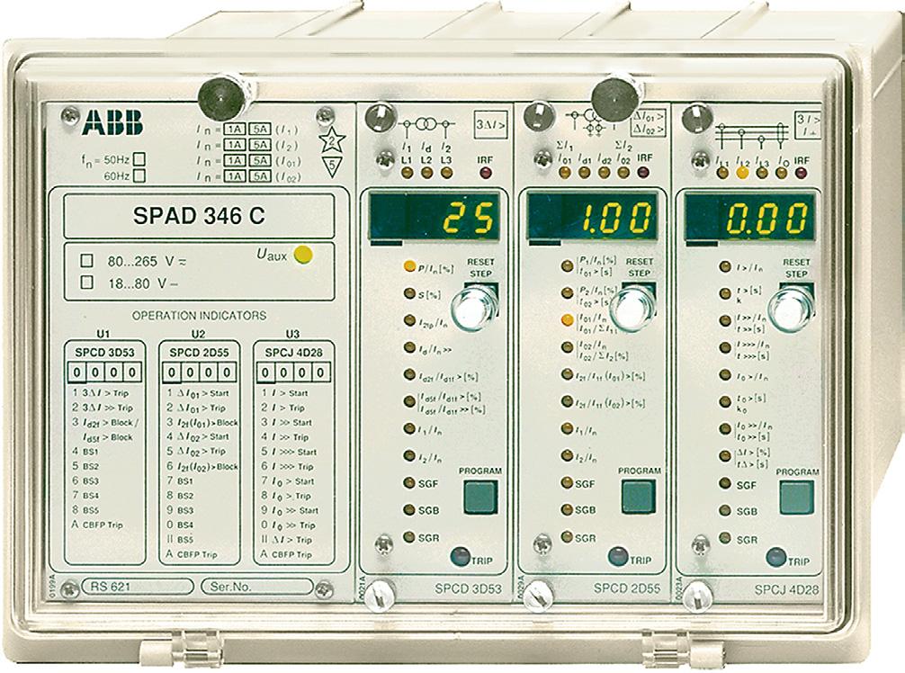
SPAD 346 C. Stabilized Differential Relay. User s manual and Technical description SPAD 346 C V ~ V. f n SPCD 3D53 SPCJ 4D28
 SPAD 6 C Stabilized Differential Relay User s manual and Technical description f n = 50Hz 60Hz I n = A 5A ( I ) I n = A 5A ( I ) I n = A 5A ( I 0 ) I n = A 5A ( I 0 ) 5 I I d L L I L I > IRF I 0 > I 0
High-set undervoltage stage with definitetime. or inverse definite minimum time (IDMT) characteristic. Low-set undervoltage stage with definitetime
 characteristic. Low-set undervoltage stage with definitetime") Issued: 5.06.999 Status: 5.06.999 Version: B/09..00 Data subject to change without notice Features Overvoltage and undervoltage protection Single- or three-phase operation High-set overvoltage stage with
Issued: 5.06.999 Status: 5.06.999 Version: B/09..00 Data subject to change without notice Features Overvoltage and undervoltage protection Single- or three-phase operation High-set overvoltage stage with
SPAE 010, 011 High Impedance Protection Relay
 SPAE 010, 011 High Impedance Protection Relay User s manual and Technical description f n = 50/60 Hz U n = 50 / 100 / 200 V 2 5 U REF > SPAE 010 0.8 U aux 0.6 1.0 RESET OK x 80... 265 V ~ _ 0.4 U > U n
SPAS 348 C. Feeder Protection Relay. User s manual and Technical description SPAS 348 C V ~ V. t 2 > [ s ] f n = 50Hz 60Hz
![SPAS 348 C. Feeder Protection Relay. User s manual and Technical description SPAS 348 C V ~ V. t 2 > [ s ] f n = 50Hz 60Hz](/thumbs/82/85869345.jpg "SPAS 348 C. Feeder Protection Relay. User s manual and Technical description SPAS 348 C V ~ V. t 2 > [ s ] f n = 50Hz 60Hz") SPAS 8 C Feeder Protection Relay User s manual and Technical description f n = 50Hz 60Hz I n = A 5A ( I ) I n = 0,A A ( I 0 ) U n 00V...0V ( U ) U n = 00V/0V/0V ( U 0 ) 5 I > I L U I L U IRF B I > I L
SPAS 8 C Feeder Protection Relay User s manual and Technical description f n = 50Hz 60Hz I n = A 5A ( I ) I n = 0,A A ( I 0 ) U n 00V...0V ( U ) U n = 00V/0V/0V ( U 0 ) 5 I > I L U I L U IRF B I > I L
Harmonic restraint earth fault or single-phase overcurrent protection
 Harmonic restraint earth fault or single-phase overcurrent protection Page 1 Issued June 1999 Changed since July 1998 Data subject to change without notice (SE970885) Features Sensitive earth fault protection
SPAJ 110 C. Earth-fault relay SPAJ 110 C. User s manual and Technical description. U aux V ~ V f n. n ( I o>> SPCJ 1C8
 SPAJ 110 C Earth-fault relay User s manual and Technical description I n = 1A 5A ( I ) f n = 50Hz 60Hz 2 5 B I o I IRF SPAJ 110 C 80...265V ~ 18...80V U aux STEP I o > I n 0.1 0.35 0.8 STEP SPCJ 1C8 REGISTERS
SPAA 341 C. Feeder Protection Relay. User s manual and Technical description SPAA 341 C. U aux V ~ V. f n. t 2 > [ s ] 0 I 0 >> Trip
![SPAA 341 C. Feeder Protection Relay. User s manual and Technical description SPAA 341 C. U aux V ~ V. f n. t 2 > [ s ] 0 I 0 >> Trip](/thumbs/72/67603349.jpg "SPAA 341 C. Feeder Protection Relay. User s manual and Technical description SPAA 341 C. U aux V ~ V. f n. t 2 > [ s ] 0 I 0 >> Trip") SPAA C Feeder Protection Relay User s manual and Technical description f n = 0Hz 0Hz I n = A A ( I ) I n = A A ( I 0B ) I n = 0,A A ( I 0 ) U n = 00V 0V 0V ( ) U 0 I > I I L I L I L I o IRF Uo I o ϕ U
SPAA C Feeder Protection Relay User s manual and Technical description f n = 0Hz 0Hz I n = A A ( I ) I n = A A ( I 0B ) I n = 0,A A ( I 0 ) U n = 00V 0V 0V ( ) U 0 I > I I L I L I L I o IRF Uo I o ϕ U
SPAA 120 C and SPAA 121 C Feeder protection relay
 SPAA 10 C and SPAA 11 C Feeder protection relay User s manual and Technical description f n = 50Hz 60Hz I n = 1A 5A ( I ) I n = 1A 5A ( I o ) U n = 100V 110V ( U o ) 5 B I > I I L1 I L3 Uo I o IRF SPAA
Relion 605 series Self-Powered Feeder Protection REJ603 Product Guide
 Relion 605 series Relion 605 series Self-Powered Feeder Protection Product Guide Contents 1 Description...3 2 Protection functions...3 3 Application...4 4 Self-supervision...4 5 Inputs and outputs...4
SPAJ 144 C. Combined overcurrent and earth-fault relay SPAJ 144 C. User s manual and Technical description A CBFP V ~ V.
 SPAJ C Combined overcurrent and earth-fault relay User s manual and Technical description f n = 0Hz 60Hz I n = A I n = A A A ( I ) ( I o) I > I I L I L I L I 0 IRF SPAJ C REGISTERS SPCJ D8 0 0 0 0 0 6
REK 510 Current injection device for earth-fault protection of a synchronous machine rotor. User s Manual
 REK 50 protection of a synchronous machine User s Manual REK 50 X 0 9 8 7 6 5 4 0 V 00 V 0 V 5 6 7 Ordering No: REK 50-AA Uau = 00/0 Vac Un = 48 V Serial No: fn = 50/60 Hz Uec = ma 600 Vdc MRS 75587-MUM
SPAJ 135 C. Combined overcurrent and earth-fault relay SPAJ 135 C. User s manual and Technical description. U aux V ~ V.
 SPAJ 135 C Combined overcurrent and earth-fault relay User s manual and Technical description I n = 1A 5A ( I ) I n = 1A 5A ( I o ) f n = 50Hz 60Hz 2 5 B I L1 I L3 I o 2 I > I IRF SPAJ 135 C 80...265V
Transformer differential protection
 Transformer differential protection Page 1 Issued June 1999 Changed since July 1998 Data subject to change without notice (SE970883) Features Three phase differential protection with two, three, five or
Phase and neutral overcurrent protection
 Phase and neutral overcurrent protection Page 1 ssued June 1999 Changed since July 1998 Data subject to change without notice (SE970165) Features Two-phase or three-phase time-overcurrent and earth fault
SPAF 340 C Frequency Relay
 SPAF 0 C Frequency Relay User s manual and Technical description U n = 00V/0V/5V/0V 5 U f f < > < > df dt IRF SPAF 0 C 80...65 V ~ 8...80 V U aux OPERATION INDICATORS U U U SPCF D5 0 Stage Start Stage
SPAJ 111 C. Sensitive earth-fault relay SPAJ 111 C. User s manual and Technical description. U aux V ~ V. f n. n ( I o>> SPCJ 1C7
 SPAJ 111 C Sensitive earth-fault relay User s manual and Technical description I n = 1A 5A ( I ) f n = 50Hz 60Hz 2 5 B I o I IRF SPAJ 111 C 80...265V ~ 18...80V U aux STEP I o > [%] I n 1.0 6.0 10 STEP
Overcurrent Protection / 7SJ45
 Overcurrent Protection / SJ SIPROTEC easy SJ numerical overcurrent protection relay powered by CTs Fig. / Description SIPROTEC easy SJ numerical overcurrent protection relay powered by current transformers
SPAC 335 C and SPAC 336 C Feeder terminals
 SPAC 335 C and SPAC 336 C Feeder terminals User s manual and Technical description I n = / 5 A( I ) I n = / 5 A( I o ) f n = 50 60 Hz SPAC 335 C U n = 00 / 0 V( U o ) 5 IRF O I B I > I I L I L3 Uo I o
Instantaneous Overcurrent Relay
 Midos Type MCRI Instantaneous Overcurrent Relay Features High speed operation Not slowed by dc transients Settings readily adjustable on relay front plate Two phase and earth fault relay Figure 1: Type
)HDWXUHV Voltage restraint overcurrent stage with five different inverse or definite time characteristics
HDWXUHV Voltage restraint overcurrent stage with five different inverse or definite time characteristics") 9ROWDJHUHVWUDLQWRYHUFXUUHQW UHOD\DQGSURWHFWLRQ DVVHPEOLHV 5;,6.+DQG 5$,6. 509 033-BEN Page 1 Issued: September 2001 Changed since: June 1999 Data subject to change without notice (SE970171) (SE970896)
9ROWDJHUHVWUDLQWRYHUFXUUHQW UHOD\DQGSURWHFWLRQ DVVHPEOLHV 5;,6.+DQG 5$,6. 509 033-BEN Page 1 Issued: September 2001 Changed since: June 1999 Data subject to change without notice (SE970171) (SE970896)
Transformer and generator time-overexcitation relay and protection assemblies RXLK 2H and RALK
 Transformer and generator time-overexcitation relay and protection assemblies RXLK 2H and RALK (RXLK_2H.tif) RALK.psd Features Micro-processor based time-overexcitation relay with continuous settings for
Transformer protection IED RET 670
 Gunnar Stranne Transformer protection IED RET 670 Santiago Septiembre 5, 2006 1 Transformer protection IED RET670 2 Introduction features and applications Differential protection functions Restricted Earth
REF 610 Feeder Protection Relay. Technical Reference Manual
 REF 610 1MRS 755310 Issued: 05.10.2004 Version: A/05.10.2004 REF 610 Contents 1. Introduction...6 1.1. About this manual...6 1.2. The use of the relay...6 1.3. Features...6 1.4. Guarantee...8 2. Safety
Time over/underfrequency relay with protection assemblies
 Time over/underfrequency relay with protection assemblies RXFK 2H and RAFK 509 009-BEN Page 1 Issued June 1999 Changed since July 1998 Data subject to change without notice (SE970104) (SE970108) Features
PD300. Transformer, generator and motor protection Data sheet
 PD300 Transformer, generator and motor protection Data sheet DSE_PD300_eng_AO No part of this publication may be reproduced by whatever means without the prior written permission of Ingeteam T&D. One of
NPRG860 & NPRG870 perform synchronization and paralleling of generators with electrical network. NPRG860 features a speed adjustment function.
 REGULATION AUTOMATIC SYNCHRONIZER for GENERATOR NPRG860 & NPRG870 perform synchronization and paralleling of generators with electrical network. NPRG860 features a speed adjustment function. NPRG870 adds
SIPROTEC easy 7SJ46 Numerical Overcurrent Protection Relay
 Overcurrent Protection / 7SJ46 SIPROTEC easy 7SJ46 Numerical Overcurrent Protection Relay Function overview Fig. /11 Description The SIPROTEC easy 7SJ46 is a numerical overcurrent protection relay which
Plug-in microprocessor controlled multifuncional relay with automatic shorting of c.t.
 Multifunctional relay Page 1 Issued: July 1998 Changed: since April 1989 Data subject to change without notice Features Plug-in microprocessor controlled multifuncional relay with automatic shorting of
NPRG860 NPRG870 REGULATION. Automatic Synchronizer for Generator
 REGULATION Automatic Synchronizer for Generator NPRG860 & NPRG870 perform synchronization and paralleling of generators with electrical network. NPRG860 features a speed adjustment function. NPRG870 adds
presentation contents application advantages
 presentation contents page presentation protection functional and connection schemes other connection schemes connection characteristics 9 installation 0 commissioning ordering information Sepam 00 is
T/3000 T/3000. Substation Maintenance and Commissioning Test Equipment
 T/3000 Substation Maintenance and Commissioning Test Equipment MULTI FUNCTION SYSTEM FOR TESTING SUBSTATION EQUIPMENT SUCH AS: CURRENT, VOLTAGE AND POWER TRANSFORMERS, ALL TYPE OF PROTECTION RELAYS, ENERGY
Differential Protection with REF 542plus Feeder Terminal
 Differential Protection with REF 542plus Application and Setting Guide kansikuva_bw 1MRS 756281 Issued: 09.01.2007 Version: A Differential Protection with REF 542plus Application and Setting Guide Contents:
SPAS 120 C Directional earth-fault relay
 SPAS 120 C Directional earth-fault relay User s manual and Technical description B I 2 f n = 0Hz 60Hz I n = 1A A ( I o ) U n = 100V 110V ( U o ) U o I o I ϕ IRF SPAS 120 C 80...26V ~ 18...80V U aux I ϕ
N. TEST TEST DESCRIPTION
 Multi function system for testing substation equipment such as: current, voltage and power transformers, all type of protection relays, energy meters and transducers Primary injection testing capabilities
N. TEST TEST DESCRIPTION
 Multi function system for testing substation equipment such as: current, voltage and power transformers, over-current protection relays, energy meters and transducers Primary injection testing capabilities
Time-overcurrent relays and protection assemblies
 Time-overcurrent relays and protection Page 1 509 002-BEN Issued January 2004 Revision: A Data subject to change without notice (SE970134) (SE970150) Features RXIDK 2H relay and Single-, two-, three-phase
Current and voltage measuring relays RXIK 1, RXEEB 1 and RXIB 24
 Current and voltage measuring relays RXIK 1, RXEEB 1 and RXIB 24 RXIK 1 (RXIK_1.tif) RXEEB 1 (RXEEB_1.tif) RXIB 24 (RXIB_24.tif) Features RXIK low current relay, 50-60 Hz and dc High sensitivity 0,5-2
Protection and control. Sepam range Sepam 100 LA Self-powering protection. Merlin Gerin Square D Telemecanique
 Protection and control Sepam range Sepam 0 LA Self-powering protection Merlin Gerin Square D Telemecanique presentation contents page presentation protection functional and connection schemes other connection
SPAC 320 C. Motor protection terminal. User s manual and Technical description SPAC 320 C. U aux V _ V _ I >> / I.
 SPAC 30 C Motor protection terminal User s manual and Technical description f n = 50 60 Hz I n = / 5 A ( I ) I n = / 5 A( I o) SPAC 30 C 5 IRF O I 3I >> 3 I I L I L I L3 I o IRF TEST INTERLOCK GAS PRESSURE
www. ElectricalPartManuals. com Transformer Differential Relay MD32T Transformer Differential Relay
 Transformer Differential Relay The MD3T Transformer Differential Relay is a member of Cooper Power Systems Edison line of microprocessor based protective relays. The MD3T relay offers the following functions:
SPAJ 160 C. Capacitor protection relay SPAJ 160 C. User s manual and Technical description V ~ V 3I > 3I < f n 2 > TRIP.
 SPAJ 60 C Capacitor protection relay User s manual and Technical description I n = A 5A ( I ) I n = A 5A ( I ) f n = 50Hz 60Hz 5 3I > I 3I < I L I L I L3 I c IRF SPAJ 60 C 80...65V ~ 8...80V SPCJ 4D40
IRI1-ER - Stabilized Earth Fault Current Relay
 IRI1-ER - Stabilized Earth Fault Current Relay TB IRI1-ER 02.97 E 1 Contents 1. Summary 2. Applications 3. Characteristics and features 4. Design 4.1 Connections 4.1.1 Analog inputs 4.1.2 Output relays
Multimeter 500CVD21 RTU500 series
 Remote Terminal Units - Data sheet Multimeter 500CVD21 RTU500 series CT/VT interface with 4 voltage and 24 current inputs for direct monitoring of 3/4 wire 0 300 V AC (line to earth), 0...500 V AC (phase
Type CP-S, CP-C & CP-A Switch mode
 Switch mode power CP-S, CP-C & CP-A Switch mode Characteristics CP-S and CP-C range Output current 5 A, 10 A and 20 A Integrated power reserve of up to 50 % 5 A and 10 A devices with pluggable connecting
User s manual and Technical description. Self-Powered Feeder Protection REJ603
 and Technical description Self-Powered Feeder Protection 2 Document ID: Issued: 18.02.2008 Revision: A Product version:1.0 Copyright 2008 ABB. All rights reserved 3 Copyright This document and parts thereof
SFIBER Fibre-optic Option Card for Lon Star Coupler RER 111. Technical Reference Manual
 SFIBER Fibre-optic Option Card for Lon Star Coupler RER 111 Technical Reference Manual 1MRS 750106-MUM Issued: 21.11.1996 Version: B2/18.2.2000 Checked: M.K. Approved: T.S. Fibre-optic Option Card for
Compact current relay and protection assemblies RXHL 401 and RAHL 401
 Compact current relay and protection assemblies RXHL 401 and RAHL 401 (xx00000120.tif) Features Three phase compact current relay for: Phase overcurrent protection, three stages Earth-fault overcurrent
TD 1000 PLUS. Secondary Injection Relay Test Set. Designed for testing relays and transducers
 Secondary Injection Relay Test Set Designed for testing relays and transducers Two current outputs to test differential relays Convertible current and voltage generator With phase angle shifter Frequency
RETROFITTING. Motor Protection Relay. Two mountings are available, Flush Rear Connection (EDPAR) or Projecting Rear Connection (SDPAR).
 or Projecting Rear Connection (SDPAR).") RETROFITTING Motor Protection Relay NPM800R (R2 case) and NPM800RE (R3 case) are dedicated to the refurbishment of 7000 series (R2 and R3 cases) of CEE relays providing the protection of medium voltage
RETROFITTING Motor Protection Relay NPM800R (R2 case) and NPM800RE (R3 case) are dedicated to the refurbishment of 7000 series (R2 and R3 cases) of CEE relays providing the protection of medium voltage
Time relay RXKA 1. (xx jpg) RXKA 1
 RXKA 1") Time relay RXKA 1 (xx02000674.jpg) RXKA 1 Features For protection, control, signal and industrial applications On-delay and Off-delay functions Continuous and pulse output functions Setting range 0.1-320
Time relay RXKA 1 (xx02000674.jpg) RXKA 1 Features For protection, control, signal and industrial applications On-delay and Off-delay functions Continuous and pulse output functions Setting range 0.1-320
SPECIFICATION FOR OVERCURRENT RELAYS
 SPECIFICATION FOR OVERCURRENT RELAYS 1/9 1. Procedure A manufacturer willing to classify an overcurrent relay according to this specification should provide: A complete file providing a clear, unambiguous
Current monitoring relays CM-SRS.2 for single-phase AC/DC currents
 Data sheet Current monitoring relays CM-SRS.2 for single-phase AC/DC currents For the monitoring of currents in single-phase AC/DC systems, ABB s CM range comprises a wide selection of powerful and compact
HV / MV / LV electrical network quality analyzers Class A. Communication port: local, modem, integrated Ethernet, multi-point
 2010 MAP Range HV / MV / LV electrical network quality analyzers Class A > Network quality Analyzers PRODUCT ADVANTAGES COMPLIANT with the EN 61000-4-30 standard, Class A DETECTION of the fault LOCATION
DATASHEET - ETR4-70-A. Delivery program. Timing relay, 2W, 0.05s-100h, multi-function, VAC/DC, potentiometer connection
 DATASHEET - ETR4-70-A Delivery program Timing relay, 2W, 0.05s-100h, multi-function, 24-240VAC/DC, potentiometer connection Part no. ETR4-70-A Catalog No. 031888 Eaton Catalog No. XTTR6A100H70B EL-Nummer
IRI1-ER - Stabilized Earth Fault Current Relay. Manual IRI1-ER (Revision A)
") IRI1-ER - Stabilized Earth Fault Current Relay Manual IRI1-ER (Revision A) Woodward Manual IRI-ER GB Woodward Governor Company reserves the right to update any portion of this publication at any time.
IRI1-ER - Stabilized Earth Fault Current Relay Manual IRI1-ER (Revision A) Woodward Manual IRI-ER GB Woodward Governor Company reserves the right to update any portion of this publication at any time.
BUS2000 Busbar Differential Protection System
 BUS2000 Busbar Differential Protection System Differential overcurrent system with percentage restraint protection 1 Typical Busbar Arrangements Single Busbar Double Busbar with Coupler Breaker and a Half
ASHIDA Numerical 3OC + 1EF Protection Relay
 PROTH. ERR L5 PKP FAULT DT REC LOCK BF L6 L7 CLOSE TRIP ADR 241B Protection Features : 4 Element (3 Phase + EF + Sensitive EF) Over current IDMT/DMT with instant trip. Programmable (Non- Volatile) Setting
DATASHEET - ETR4-51-A. Delivery program. Technical data General. Timing relay, star-delta, 50 ms, 1W, 3-60s, VAC/DC
 DATASHEET - ETR4-51-A Timing relay, star-delta, 50 ms, 1W, 3-60s, 24-240VAC/DC Part no. ETR4-51-A Catalog No. 031884 Eaton Catalog No. XTTR6A60S51B EL-Nummer 0004133308 (Norway) Delivery program Product
Earth fault protection for isolated neutral systems with frequency converters
 Earth fault protection for isolated neutral systems with frequency converters Page Issued June 999 Changed since July 998 Data subject to change without notice (SE97089) Features Earth fault and flash-over
4Q POWER AMPLIFIERS AC AND DC 3000VA 3x3000VA
 PERFORMANCES High accuracy High stability Fast transients High inrush current facilities Wide bandwidth 25 khz at -3dB Internal waveform DC and up to 10 khz Very low distortion Quadrant change without
Fixed Series Compensation
 Fixed Series Compensation High-reliable turnkey services for fixed series compensation NR Electric Corporation The Fixed Series Compensation (FSC) solution is composed of NR's PCS-9570 FSC control and
Modular multifunction generator protection
 Modular multifunction generator Page 1 Issued June 1999 Changed since July 1998 Data subject to change without notice (SE970186) Features is a modular generator that enables selection of the desired in
Catalogue 1SFC en, Edition 3 November 2003 Supersedes Catalogue 1SFC en, Edition 2 November Arc Guard System TVOC
 Catalogue 1SFC 266006-en, Edition 3 November 2003 Supersedes Catalogue 1SFC 266006-en, Edition 2 November 2000 Arc Guard System TVOC System units The two units of the are used as below: Approvals 1. with
T 1000 PLUS. Secondary Injection Relay Test Set. Designed for testing relays and transducers
 Secondary Injection Relay Test Set Designed for testing relays and transducers Microprocessor controlled With phase angle shifter Frequency generator Test results and settings are saved into local memory
POWER AMPLIFIERS 4 QUADRANTS 3x500 VA to 3x1500 VA - THREE-PHASES
 PERFORMANCES High accuracy High stability Fast transients High inrush current facilities Wide bandwidth Very low distortion Quadrant change without transition Very low output impedance Low noise RS232
MHCO MHCO-RI. General Characteristics The transducer MHCO provide a measurement of current or voltage fully isolated and safe.
 -TVI -RI -RV D.C. MEASURING CONVERTER Converter for D.C. Current and/or Voltage measurement. Direct connection to D.C. mains rating up to 4 kvcc. Fully isolated multi-voltage power suppy. Fiber optic connection
ABB 1. Multifunctional three-phase monitoring relays. CM-MPS.11, CM-MPS-21, CM-MPS.31 and CM-MPS.41 Data sheet. Features. Approvals. Marks.
 2CDC 251 048 F0t08 CM-MPS.11 2CDC 251 049 F0t08 CM-MPS.21 2CDC 251 050 F0t08 CM-MPS.31 2CDC 251 051 F0t08 CM-MPS.41 R/T: yellow LED - relay status, timing F1: red LED - fault message F2: red LED - fault
DIFFERENTIAL CURRENT GENERATOR «POCDIF» (AC/DC - 32A - 50V - 12 ranges)
") PERFORMANCES 12 ranges of AC current from 16 ma to 128 A peak AC permanent current up to 26 ARMS Nine ranges of DC permanent current from 16 ma to 12 A DC current ± 6mA or ± 10 ma stackable to AC current
PERFORMANCES 12 ranges of AC current from 16 ma to 128 A peak AC permanent current up to 26 ARMS Nine ranges of DC permanent current from 16 ma to 12 A DC current ± 6mA or ± 10 ma stackable to AC current
High-Tech Range. IRI1-ER- Stablized Earth Fault Current Relay. C&S Protection & Control Ltd.
 High-Tech Range IRI1-ER- Stablized Earth Fault Current Relay C&S Protection & Control Ltd. Contents 1. Summary 7. Housing 2. Applications 3. Characteristics and features 4. Design 7.1 Individual housing
Reyrolle Protection Devices. 7SG14 Duobias M Transformer Protection. Answers for energy
 Reyrolle Protection Devices 7SG4 Duobias M Transformer Protection Answers for energy 7SG4 Duobias M Transformer Protection Description Optional Functionality High Impedance Restricted Earth Fault per winding
200ADM-P. Current Injection System with Phase Shift A 3.000s 2.000A 50.00Hz 0.0. Features
 CT ratio Power Harmonics ac+dc 200ADM-P Current Injection System with Phase Shift Features 0-200A output current True RMS metering with 1 cycle capture Variable auxiliary AC voltage/current output with
Current monitoring relays CM-SRS.2 For single-phase AC/DC currents
 Data sheet Current monitoring relays CM-SRS.2 For single-phase AC/DC currents The CM-SRS.2 is an electronic current monitoring relay that protects single-phase mains (DC or AC) from over- and undercurrent
Electronic timer CT-AHS.22 OFF-delayed with 2 c/o (SPDT) contacts
 contacts") Data sheet Electronic timer CT-AHS.22 OFF-delayed with 2 c/o (SPDT) contacts The CT-AHS.22 is an electronic timer from the CT-S range with OFF-delay and 10 time ranges. All electronic timers from the CT-S
Data sheet Electronic timer CT-AHS.22 OFF-delayed with 2 c/o (SPDT) contacts The CT-AHS.22 is an electronic timer from the CT-S range with OFF-delay and 10 time ranges. All electronic timers from the CT-S
Type: ADR233A (ADITYA V2 Series) (Preliminary) ASHIDA Numerical 3 Phase Tx. Differential Protection Relay
 (Preliminary) ASHIDA Numerical 3 Phase Tx. Differential Protection Relay") Ashida Numerical 3 Directional Phase Tx. 3O/C Differential + 1E/F Protection PROTH. ERR FAULT 87 L5 L6 REF L7 BF TRIP ADR 233B_V2 233A_V2 Protection Features: 3Phase Tx. Differential Protection + REF Programmable
Ashida Numerical 3 Directional Phase Tx. 3O/C Differential + 1E/F Protection PROTH. ERR FAULT 87 L5 L6 REF L7 BF TRIP ADR 233B_V2 233A_V2 Protection Features: 3Phase Tx. Differential Protection + REF Programmable
XD1-T Transformer differential protection relay. Manual XD1-T (Revision A)
") XD1-T Transformer differential protection relay Manual XD1-T (Revision A) Woodward Manual XD1-T GB Woodward Governor Company reserves the right to update any portion of this publication at any time. Information
XD1-T Transformer differential protection relay Manual XD1-T (Revision A) Woodward Manual XD1-T GB Woodward Governor Company reserves the right to update any portion of this publication at any time. Information
ABB 1. Multifunctional three-phase monitoring relays. CM-MPN.52, CM-MPN.62 and CM-MPN.72 Data sheet. Features. Approvals. Marks.
 2CDC 251 054 F0t08 CM-MPN.52 2CDC 251 055 F0t08 CM-MPN.62 2CDC 251 056 F0t08 CM-MPN.72 Features Monitoring of three-phase mains for phase sequence (can be switched off), phase failure, over- and undervoltage
Three-phase monitoring relays
 2CDC 251 046 F0t08 Features Monitoring of three-phase mains for phase sequence, phase failure, phase unbalance Threshold value for phase unbalance adjustable as absolute value Tripping delay can be adjusted
BE1-67N GROUND DIRECTIONAL OVERCURRENT RELAY FEATURES ADDITIONAL INFORMATION. FUNCTIONS AND FEATURES Pages 2-4. APPLICATIONS Page 2
 BE1-67N GROUND DIRECTIONAL OVERCURRENT RELAY The BE1-67N Ground Directional Overcurrent Relay provides ground fault protection for transmission and distribution lines by sensing the direction and magnitude
Thermistor motor protection relays
 Thermistor motor protection relays Content Benefits and advantages... / 68 Selection table... / 68 Ordering details CM-MSE... / 69 CM-MSS... / 69 CM-MSN... / 7 PTC sensor C0... / 7 Technical data... /
ABB NEW. Three-phase monitoring relays. CM-PVS.31 and CM-PVS.41 Data sheet. Features J. Approvals. Marks. Order data. Order data - Accessories
 2CDC 251 042 F0t08 CM-PVS.31 Features Monitoring of three-phase mains for phase sequence (can be switched off), phase failure, over- and undervoltage Threshold values for over- and undervoltage are adjustable
XP2-R Power and Reverse Power Relay
 XP2-R Power and Reverse Power Relay Manual XP2-R (Revision C) Woodward Manual XP2-RE Woodward reserves the right to update any portion of this publication at any time. Information provided by Woodward
Electronic timer CT-AHS.22 OFF-delayed with 2 c/o (SPDT) contacts
 contacts") Data sheet Electronic timer CT-AHS.22 OFF-delayed with 2 c/o (SPDT) contacts The CT-AHS.22 is an electronic timer from the CT-S range with true OFF-delay and 10 time ranges. All electronic timers from
Data sheet Electronic timer CT-AHS.22 OFF-delayed with 2 c/o (SPDT) contacts The CT-AHS.22 is an electronic timer from the CT-S range with true OFF-delay and 10 time ranges. All electronic timers from
3 Pole high impedance differential relay 7VH83
 Fig 1. High impedance differential protection relay 7VH83 Features l Integral CT shorting relay. l Robust solid state design. l Inrush stabilisation through filtering. l Fast operating time. l LED indicator.
Voltage monitoring relay CM-EFS.2 For single-phase AC/DC voltages
 Data sheet Voltage monitoring relay CM-EFS.2 For single-phase AC/DC voltages The CM-EFS.2 is an electronic voltage monitoring relay that provides reliable monitoring of voltages as well as detection of
Electronic timer CT-YDE Star-delta change-over with 1 c/o (SPDT) contact
 contact") Data sheet Electronic timer CT-YDE Star-delta change-over with c/o (SPDT) contact The CT-YDE is an electronic time relay with star-delta change-over. It is from the CT-E range. The CT-E range is the economic
Data sheet Electronic timer CT-YDE Star-delta change-over with c/o (SPDT) contact The CT-YDE is an electronic time relay with star-delta change-over. It is from the CT-E range. The CT-E range is the economic
PS-3000-AVAS PS-5000-AVAS DC SOURCE FOR AUTOMOTIVE TESTS
 PERFORMANCES High accuracy High stability Fast times of transition High inrush current Wide bandwidth Switching from Q1 to Q4 without transition Very low output impedance Ripple & noise superposition Dips
Transformer Fault Categories
 Transformer Fault Categories 1. Winding and terminal faults 2. Sustained or uncleared external faults 3. Abnormal operating conditions such as overload, overvoltage and overfluxing 4. Core faults 1 (1)
Relion 605 series. Self-Powered Feeder Protection REJ603 Application manual
 Relion 605 series Relion 605 series Relion 605 series Self-Powered Feeder Protection REJ603 Application manual Document ID: 1MDU07206-YN 6 2 4 This document and parts thereof must not be reproduced or
XR1 Rotor Earth Fault Relay. Manual XR1 (Revision C)
") XR1 Rotor Earth Fault Relay Manual XR1 (Revision C) Woodward Manual XR1 (EN) Woodward Governor Company reserves the right to update any portion of this publication at any time. Information provided by
XR1 Rotor Earth Fault Relay Manual XR1 (Revision C) Woodward Manual XR1 (EN) Woodward Governor Company reserves the right to update any portion of this publication at any time. Information provided by
1 INTRODUCTION ORDER CODE / INFORMATION
 INTRODUCTION ORDER CODE / INFORMATION 269/269Plus * * * * * * 269/269Plus SV D/O.4 ORDER CODE / INFORMATION Motor management relay Standard version Drawout version Phase CT Ground CT (required for D/O
T 1000 PLUS Secondary Injection Relay Test Set
 Secondary Injection Relay Test Set Designed for testing relays and transducers Microprocessor controlled With phase angle shifter Frequency generator Test results and settings are saved into local memory
Types CDG 11 and CDG 16 Inverse Time Overcurrent and Earth Fault Relay
 Types CDG 11 and CDG 16 Inverse Time Overcurrent and Earth Fault Relay Types CDG 11 and CDG 16 Inverse Time Overcurrent and Earth Fault Relay Relay withdrawn from case Application The type CDG 11 relay
Current monitoring relays CM-SRS.1 for single-phase AC/DC currents
 Data sheet Current monitoring relays CM-SRS.1 for single-phase AC/DC currents For the monitoring of currents in single-phase AC/DC systems, ABB s CM range comprises a wide selection of powerful and compact
NEO TELE-TRONIX PVT. LTD. 6/7 Bijoygarh, Kolkata , Tel : ; Fax :
 NEO TELE-TRONIX PVT. LTD. 6/7 Bijoygarh, Kolkata - 700 032, Tel : 033 2477 3126; Fax : 033 2477 2403 www.ntplindia.com SPECIFICATION NTPL MAKE MICRO-CONTROLLER BASED AUTOMATIC 50KV/10A AC HIGH VOLTAGE
T 1000 PLUS. Secondary Injection Relay Test Set. Designed for testing relays and transducers
 Secondary Injection Relay Test Set Designed for testing relays and transducers Microprocessor controlled With phase angle shifter Frequency generator High power outputs Large graphical display Compact
XD1-T - Transformer differential protection relay
 XD1-T - Transformer differential protection relay Contents 1. Application and features 2. Design 3. Characteristics 3.1 Operating principle of the differential protection 3.2 Balancing of phases and current
DRTS 66 The new generation of advanced test equipments for Relays, Energy meters, Transducers and Power quality meters
 The new generation of advanced test equipments for Relays, Energy meters, Transducers and Power quality meters Testing all relay technologies: electromechanical, solid state, numerical and IEC61850 Manual
Electronic timer CT-TGD.12 Pulse generator with 1 c/o (SPDT) contact
 contact") Data sheet Electronic timer CT-TGD.12 Pulse generator with 1 c/o (SPDT) contact The CT-TGD.12 is an electronic time relay with the function pulse generator. It is from the CT-D range. With their MDRC profile
Data sheet Electronic timer CT-TGD.12 Pulse generator with 1 c/o (SPDT) contact The CT-TGD.12 is an electronic time relay with the function pulse generator. It is from the CT-D range. With their MDRC profile