Improving Transformer Protection
|
|
|
- Lenard Nichols
- 5 years ago
- Views:
Transcription


1 Omaha, NB October 12, 2017 Improving Transformer Protection Wayne Hartmann VP, Customer Excellence Senior Member, IEEE
2 Wayne Hartmann Senior VP, Customer Excellence Speaker Bio Beckwith Electric s top strategist for delivering innovative technology messages to the Electric Power Industry through technical forums and industry standard development. Before joining Beckwith Electric, performed in Application, Sales and Marketing Management capacities at PowerSecure, General Electric, Siemens Power T&D and Alstom T&D. Provides strategies, training and mentoring to Beckwith Electric personnel in Sales, Marketing, Creative Technical Solutions and Engineering. Key contributor to product ideation and holds a leadership role in the development of course structure and presentation materials for annual and regional protection & control Seminars. Senior Member of IEEE, serving as a Main Committee Member of the Power System Relaying and Control Committee for over 25 years. Chair Emeritus of the IEEE PSRCC Rotating Machinery Subcommittee ( 07-10). Contributed to numerous IEEE Standards, Guides, Reports, Tutorials and Transactions, delivered Tutorials IEEE Conferences, and authored and presented numerous technical papers at key industry conferences. Contributed to McGraw-Hill's Standard Handbook of Power Plant Engineering. 2
3 Abstract Power transformers play a critical role in process continuity Transformers are subject to: Internal short circuits External short circuits Abnormal operating conditions Challenges: CT remanence & high X/R ratio Inrush Overexcitation Ground fault sensitivity 3 3
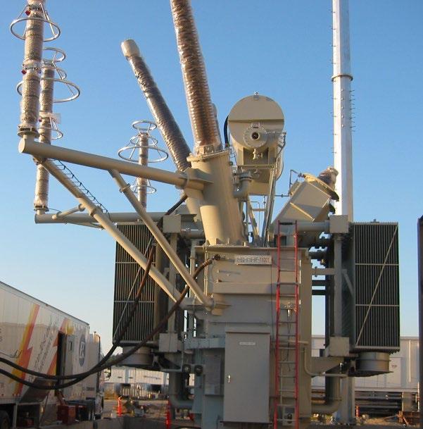

4 Transformers: T & D 4
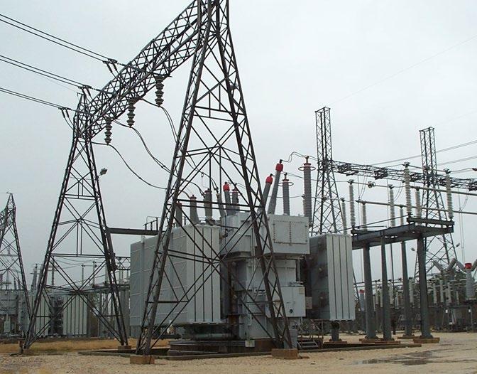
5 Transformers: T & D 5 5
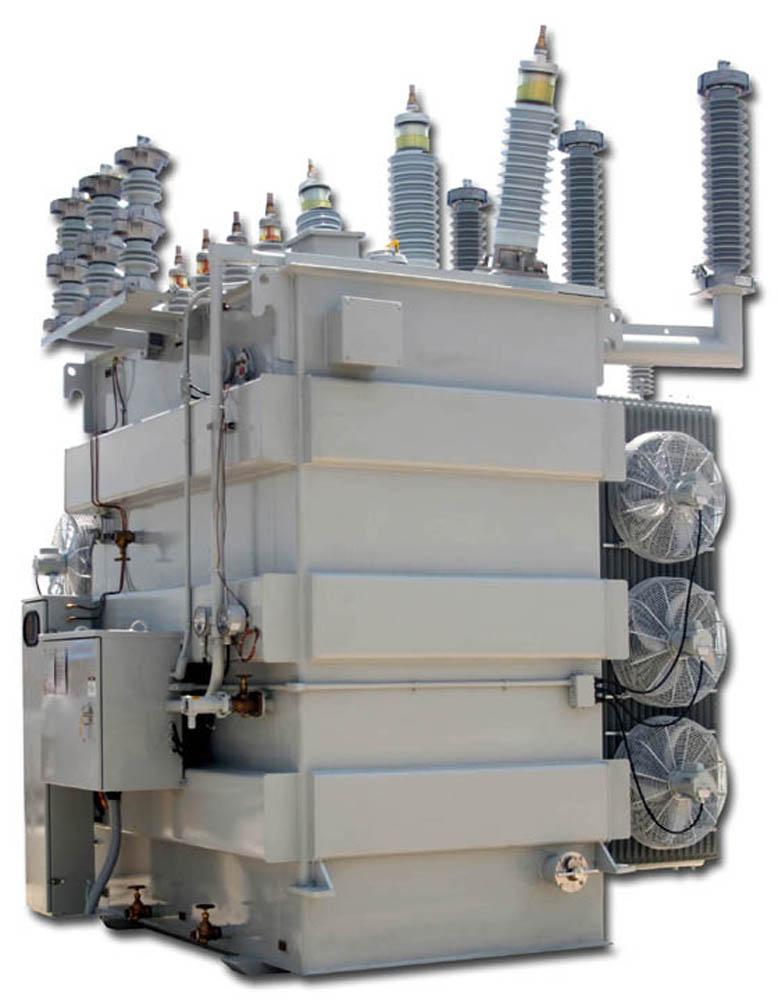
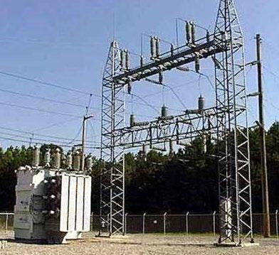
6 Transformers: T & D 6

7 Transformer: GSU Step Up 7

8 Failure! 8

9 Failure! 9

10 Failure! 10
11 Remanence & X/R Ratio: CT Saturation Remenant Flux Magnetization left behind in CT iron after an external magnetic field is removed Caused by current interruption with DC offset High X/R Ratio Increases the time constant of the CT saturation period CT saturation is increased by the above factors working alone or in combination with: Large fault or through-fault current (causes high secondary CT voltage) 11 11

12 IEEE CT Saturation Calculator The IEEE Power System Relaying & Control Committee (PSRCC) developed a simplified model for CT saturation Includes the major parameters that should be considered. Examples of saturation with a 2-node bus Fig. 1A: Internal Fault Fig. 1B: External Fault 12 12
![CT Saturation [1] Fig.](/docs-images/90/102423196/images/13-0.jpg "2: 400:5, C400, R=0.5, Offset = 0.")
13 CT Saturation [1] Fig. 2: 400:5, C400, R=0.5, Offset = 0.5, 2000A 13 13
![CT Saturation [2] Fig.](/docs-images/90/102423196/images/14-0.jpg "3: 400:5, C400, R=0.5, Offset = 0.")
14 CT Saturation [2] Fig. 3: 400:5, C400, R=0.5, Offset = 0.5, 4000A 14 14
15 CT Saturation [3] Fig. 4: 400:5, C400, R=0.5, Offset = 0.5, 8000A 15 15
![CT Saturation [4] Fig.](/docs-images/90/102423196/images/16-0.jpg "5: 400:5, C400, R=0.5, Offset = 0.")
16 CT Saturation [4] Fig. 5: 400:5, C400, R=0.5, Offset = 0.75, 8000A 16 16
![CT Saturation [5] Fig.](/docs-images/90/102423196/images/17-2.jpg "6: 400:5, C400, R=0.75, Offset = 0.")
17 CT Saturation [5] Fig. 6: 400:5, C400, R=0.75, Offset = 0.75, 8000A 17 17

: 400A = 1")

18 Differential Element Quantities Restraining versus Operating Assumptions Rated current (full load): 400A = 1 pu Maximum through or internal fault current = 20X rated = 20pu 18 18
19 Characteristic & Values Plot Pick Up: 0.35pu Slope 1 Breakpoint: 1.5pu Slope 1: 57% Slope 2 Breakpoint: 3.0pu Slope 2: 200% Relay elements from different manufacturers use different restraining and operating calculations Careful evaluation is recommended 19 Fig. 7 Modeled Test Plots 19

20 Coping with Transformer Inrush Initial energizing inrush that occurs when the transformer is energized from the completely deenergized state Sympathetic inrush that occurs when an energized transformer undergoes inrush after a neighboring transformer energizes Recovery inrush that occurs after a fault occurs and is cleared 20 20
21 Coping with Transformer Inrush Inrush current is distinguishable from fault current by the inclusion of harmonic components 2nd harmonic restraint has traditionally been applied to prevent undesired tripping of differential elements 2nd harmonic quantity depends upon the magnetizing characteristics of the transformer core and residual magnetism present in the core 21 21
22 Coping with Transformer Inrush Modern transformers tend to have: Low core losses Very steep magnetizing characteristics Exhibit lower values of 2nd harmonic Fortunately, even order harmonics are generated during inrush, not only 2nd harmonic Use 2 nd and 4 th harmonic as a restraining quantity for inrush

23 Transformer Inrush Harmonics Figs. 8a, b, c, d Inrush Currents: Actual, Fundamental, 2nd Harmonic and 4th Harmonic Levels 2nd and 4th inrush harmonics are approximately 1/5 the value of the fundamental value
 on transformer base, 0.8 power factor No Load: 1.")
24 Transformer Overexcitation Creates Excess Flux Occurs whenever the ratio of V/Hz at the secondary terminals of a transformer exceeds: Full Load: 1.05 per unit (PU) on transformer base, 0.8 power factor No Load: 1.1 PU Localized overheating and breakdown Core assembly Winding insulation 24 24
25 Coping with Transformer Overexcitation Non-laminated components at the ends of the cores begin to heat up because of the higher losses induced in them This can cause severe localized overheating in the transformer and eventual breakdown in the core assembly or winding insulation 25 25
26 Overexcitation Causes May be caused by system events 26 Figs. 9a, b, c, d Overexcitation 26

27 Increased V/Hz = Overexcitation = Excess Current 27 Fig. 10, Overexcitation Event Oscillograph 27

28 Overexcitation Harmonics: A Closer Look 28 Fig. 11, Overexcitation Event Oscillograph 28
29 Overexcitation Responds to overfluxing; excessive V/Hz 120V/60Hz = 2 = 1pu Constant operational limits o ANSI C & C loaded, 1.10 unloaded o Inverse time curves typically available for values over the constant allowable level Overfluxing is a voltage and frequency based issue Overfluxing protection needs to be voltage and frequency based (V/Hz) Apparatus (transformers and generators) is rated with V/Hz withstand curves and limits not 5 th harmonic withstand limits 29
30 Overexcitation vs. Overvoltage Overvoltage protection reacts to dielectric limits Exceed those limits and risk punching a hole in the insulation Time is not negotiable Overexcitation protection reacts to overfluxing The voltage excursion may be less than the prohibited dielectric limits (overvoltage limit) Overfluxing causes heating Time is not negotiable The excess current cause excess heating Causes cumulative damage the asset If time/level limits violated, may cause a catastrophic failure 30

31 Protect Against Overexcitation V / Hz levels indicate flux V / Hz element for alarm and trip Use manufacturer s level and time withstand curves Reset timer waits for cooling 31
32 Transformer Overexcitation: 87T Concerns For differential protection, 5th harmonic restraint has been used to prevent undesired tripping by blocking the differential element Issue with blocking the differential element is if a single-phase fault or two-phase fault occurs in the transformer, and one phase remains unfaulted, the differential element remains blocked
33 Transformer Overexcitation: 87T Concerns Overexcitation in T&D systems is typically caused by the voltage component of the V/Hz value The transformer is more inclined to fault during an overexcitation event as the voltage is higher than rated. It is at this moment that the differential element should not be blocked 33 33
34 Transformer Overexcitation: 87T Concerns Improved strategy: Raise the pickup of the differential element during overexcitation Keeps the element secure against undesired tripping Allows the element to quickly respond to an internal fault that occurs during the overexcitation event
35 Transformer Overexcitation: 87T Concerns 35 Fig. 12, Overexcitation Event Oscillograph 35
36 Ground Fault Security 25MVA 69kV:13.8kV 3Y 400:5 400A Multifunction Differential Relay 3ɸ 3I 0 87 I N 87 GD 3ɸ 3Y 1200:5 1 3ɸ Low level ground fault current difficult to detect with phase differential Ground differential offers far greater sensitivity while remaining secure 36 Fig. 13, Ground Differential Protection Application 36
37 Ground Fault Security 37 Fig. 14, 87GD with Internal Fault, Double Fed 37
38 Ground Fault Security 38 Fig. 15, 87GD with External Through Fault 38
39 Ground Fault Security 39 Fig. 16, 87GD with Internal Fault, Single Feed 39
40 Through Fault Provides protection against cumulative through fault damage TF Typically alarm function Through Fault 40


41 Through Fault A transformer is like a motor that does not spin There are still forces acting in it That is why we care about limiting through-faults Electric Power Engineering Handbook 41
42 Through-Fault Monitoring Protection against heavy prolonged through faults Transformer Category -IEEE Std. C Curves Minimum nameplate (kva) Category Single-Phase Three-Phase I II III , ,000 IV Above 10,000 Above 30,000 42

43 Through-Fault Damage Mechanisms Thermal Limits for prolonged through-faults typically 1-5X rated Time limit of many seconds Mechanical Limits for shorter duration through-faults typically greater than 5X rated Time limit of few seconds NOTE: Occurrence limits on each Transformer Class Graph Standard Handbook for Electrical Engineers 43
 400 300")

44 Through-Fault Category 1 (15 kva 500 kva) From IEEE C
 through the Z results in higher energy (forces) From IEEE C37.")
45 Through-Fault Category 2 (501 kva 5 MVA) Through-Fault damage increases for a given amount of transformer Z%, as more I (I 2 ) through the Z results in higher energy (forces) From IEEE C
46 Cat. 2 & 3 Fault Frequency Zones (501 kva - 30 MVA) From IEEE C

47 Through-Fault Category MVA 30 MVA Through-Fault damage increases for a given amount of transformer Z%, as more I (I 2 ) through the Z results in higher energy (forces) From IEEE C
 through the Z results in higher energy (forces)")
48 Through-Fault Category 4 (>30 MVA) Through-Fault damage increases for a given amount of transformer Z%, as more I (I 2 ) through the Z results in higher energy (forces) 48
49 Current Summing & Through-Fault Winding 4 (W4) 3-CT Winding 1 (W1) 3-CT 50BF Sum TF 51 Sum 49 Sum Σ 59G VT 1-VT V G O/U 51N Sum 87GD 50N 50N BF Sum 50G 51G Winding 2 (W2) 1-CT Winding 3 (W3) 50N 87GD 50G 51G 1-CT 51N 50N R R 50N BF 51N 50N BF B C 87H 87T 50BF CT 50BF CT 49
50 Through-Fault Function Settings (TF) Should have a current threshold to discriminate between mechanical and thermal damage areas May ignore through-faults in the thermal damage zone that fail to meet recording criteria Should have a minimum through-fault event time delay to ignore short transient through-faults Should have a through-fault operations counter Any through-fault that meets recording criteria increments counter Should have a preset for application on existing assets with through-fault history Should have cumulative I 2 t setting How total damage is tracked Should use inrush restraint to not record inrush periods Inrush does not place the mechanical forces to the transformer as does a through-fault 50
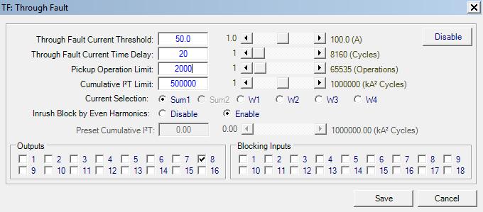
51 Through-Fault Function Settings (TF) 51
52 Summary and Conclusions The operating principle and quantities for restraint and operate should be understood Analysis of internal and external faults with various fault current levels, offset and remanent flux levels can help determine settings IEEE CT secondary circuit performance model The use of 2nd and 4th harmonics restraint can provide improved security for all types of inrush phenomena versus use of 2nd harmonic alone
53 Summary and Conclusions The use of 5th harmonic restraint can be improved by raising the pickup when 5th harmonic from overexcitation is encountered This enhances dependability from the typical employment of 5th harmonic restraint that blocks the differential element Overexcitation protection (V/Hz) should be employed on transformers Voltage inputs required 53 53
54 Summary and Conclusions The use of ground differential to supplement phase differential provides improved sensitivity and dependability to detect ground faults in transformers Directional supervision helps improve security Through-fault protection helps quantify the events so something can be done about them Should employ supervisions to ensure true through-fault events are logged 54 54
Transformer Protection
 1 Presenter Contact Info Wayne Hartmann Senior VP, Customer Excellence Beckwith Electric Company whartmann@beckwithelectric.com 904 238 3844 Wayne is the top strategist for delivering innovative technology
Transformer Protection Principles
 Transformer Protection Principles 1. Introduction Transformers are a critical and expensive component of the power system. Due to the long lead time for repair of and replacement of transformers, a major
Hands On Relay School Open Lecture Transformer Differential Protection Scott Cooper
 Hands On Relay School Open Lecture Transformer Differential Protection Scott Cooper Transformer Differential Protection ntroduction: Transformer differential protection schemes are ubiquitous to almost
System Protection and Control Subcommittee
 Power Plant and Transmission System Protection Coordination Volts Per Hertz (24), Undervoltage (27), Overvoltage (59), and Under/Overfrequency (81) Protection System Protection and Control Subcommittee
Catastrophic Relay Misoperations and Successful Relay Operation
 Catastrophic Relay Misoperations and Successful Relay Operation Steve Turner (Beckwith Electric Co., Inc.) Introduction This paper provides detailed technical analysis of several catastrophic relay misoperations
Protection of a 138/34.5 kv transformer using SEL relay
 Scholars' Mine Masters Theses Student Theses and Dissertations Fall 2016 Protection of a 138/34.5 kv transformer using SEL 387-6 relay Aamani Lakkaraju Follow this and additional works at: http://scholarsmine.mst.edu/masters_theses
Hands On Relay School Open Lecture Transformer Differential Protection Scott Cooper
 Hands On Relay School Open Lecture Transformer Differential Protection Scott Cooper Transformer Differential Protection ntroduction: Transformer differential protection schemes are ubiquitous to almost
Transformer Protection
 Transformer Protection Transformer Protection Outline Fuses Protection Example Overcurrent Protection Differential Relaying Current Matching Phase Shift Compensation Tap Changing Under Load Magnetizing
Modern transformer relays include a comprehensive set of protective elements to protect transformers from faults and abnormal operating conditions
 1 Transmission transformers are important links in the bulk power system. They allow transfer of power from generation centers, up to the high-voltage grid, and to bulk electric substations for distribution
PROTECTION OF TRANSFORMERS M-3311A TEST PLAN
 PROTECTION OF TRANSFORMERS M-3311A TEST PLAN Chuck Mozina -- is a Consultant, Protection and Protection Systems for Beckwith Electric and resides in Palm Harbor (near Tampa), Florida.. He is a Life Fellow
Impact of transient saturation of Current Transformer during cyclic operations Analysis and Diagnosis
 1 Impact of transient saturation of Current Transformer during cyclic operations Analysis and Diagnosis BK Pandey, DGM(OS-Elect) Venkateswara Rao Bitra, Manager (EMD Simhadri) 1.0 Introduction: Current
Protecting power transformers from common adverse conditions
 Protecting power transformers from common adverse conditions by Ali Kazemi, and Casper Labuschagne, Schweitzer Engineering Laboratories Power transformers of various size and configuration are used throughout
TECHNICAL BULLETIN 004a Ferroresonance
 May 29, 2002 TECHNICAL BULLETIN 004a Ferroresonance Abstract - This paper describes the phenomenon of ferroresonance, the conditions under which it may appear in electric power systems, and some techniques
Power Plant and Transmission System Protection Coordination Fundamentals
 Power Plant and Transmission System Protection Coordination Fundamentals NERC Protection Coordination Webinar Series June 2, 2010 Jon Gardell Agenda 2 Objective Introduction to Protection Generator and
NERC Protection Coordination Webinar Series June 23, Phil Tatro
 Power Plant and Transmission System Protection Coordination Volts Per Hertz (24), Undervoltage (27), Overvoltage (59), and Under/Overfrequency (81) Protection NERC Protection Coordination Webinar Series
Detecting and Managing Geomagnetically Induced Currents With Relays
 Detecting and Managing Geomagnetically Induced Currents With Relays Copyright SEL 2013 Transformer Relay Connections Voltage Current Control RTDs Transformer Protective Relay Measures differential current
Waterpower '97. Upgrading Hydroelectric Generator Protection Using Digital Technology
 Waterpower '97 August 5 8, 1997 Atlanta, GA Upgrading Hydroelectric Generator Protection Using Digital Technology Charles J. Beckwith Electric Company 6190-118th Avenue North Largo, FL 33773-3724 U.S.A.
Transformer protection IED RET 670
 Gunnar Stranne Transformer protection IED RET 670 Santiago Septiembre 5, 2006 1 Transformer protection IED RET670 2 Introduction features and applications Differential protection functions Restricted Earth
Setting and Verification of Generation Protection to Meet NERC Reliability Standards
 1 Setting and Verification of Generation Protection to Meet NERC Reliability Standards Xiangmin Gao, Tom Ernst Douglas Rust, GE Energy Connections Dandsco LLC. Abstract NERC has recently published several
Generator Protection GENERATOR CONTROL AND PROTECTION
 Generator Protection Generator Protection Introduction Device Numbers Symmetrical Components Fault Current Behavior Generator Grounding Stator Phase Fault (87G) Field Ground Fault (64F) Stator Ground Fault
A Tutorial on the Application and Setting of Collector Feeder Overcurrent Relays at Wind Electric Plants
 A Tutorial on the Application and Setting of Collector Feeder Overcurrent Relays at Wind Electric Plants Martin Best and Stephanie Mercer, UC Synergetic, LLC Abstract Wind generating plants employ several
System Protection and Control Subcommittee
 Power Plant and Transmission System Protection Coordination Reverse Power (32), Negative Sequence Current (46), Inadvertent Energizing (50/27), Stator Ground Fault (59GN/27TH), Generator Differential (87G),
www. ElectricalPartManuals. com Transformer Differential Relay MD32T Transformer Differential Relay
 Transformer Differential Relay The MD3T Transformer Differential Relay is a member of Cooper Power Systems Edison line of microprocessor based protective relays. The MD3T relay offers the following functions:
Overcurrent and Overload Protection of AC Machines and Power Transformers
 Exercise 2 Overcurrent and Overload Protection of AC Machines and Power Transformers EXERCISE OBJECTIVE When you have completed this exercise, you will understand the relationship between the power rating
Transformer Fault Categories
 Transformer Fault Categories 1. Winding and terminal faults 2. Sustained or uncleared external faults 3. Abnormal operating conditions such as overload, overvoltage and overfluxing 4. Core faults 1 (1)
Analysis of Modern Digital Differential Protection for Power Transformer
 Analysis of Modern Digital Differential Protection for Power Transformer Nikhil Paliwal (P.G. Scholar), Department of Electrical Engineering Jabalpur Engineering College, Jabalpur, India Dr. A. Trivedi
Keywords: Transformer, differential protection, fuzzy rules, inrush current. 1. Conventional Protection Scheme For Power Transformer
 Vol. 3 Issue 2, February-2014, pp: (69-75), Impact Factor: 1.252, Available online at: www.erpublications.com Modeling and Simulation of Modern Digital Differential Protection Scheme of Power Transformer
www. ElectricalPartManuals. com Generator Differential Relay MD32G Rotating Machine Differential Relay
 Generator Differential Relay The MD3G Rotating Machine Differential Relay is a member of Cooper Power Systems Edison line of microprocessor based protective relays. The MD3G relay offers the following
NERC Requirements for Setting Load-Dependent Power Plant Protection: PRC-025-1
 NERC Requirements for Setting Load-Dependent Power Plant Protection: PRC-025-1 Charles J. Mozina, Consultant Beckwith Electric Co., Inc. www.beckwithelectric.com I. Introduction During the 2003 blackout,
PD300. Transformer, generator and motor protection Data sheet
 PD300 Transformer, generator and motor protection Data sheet DSE_PD300_eng_AO No part of this publication may be reproduced by whatever means without the prior written permission of Ingeteam T&D. One of
IMPROVEMENTS IN PROTECTION AND COMMISSIONING OF DIGITAL TRANSFORMER RELAYS AT MEDIUM VOLTAGE INDUSTRIAL FACILITIES
 IMPOVEMENTS IN POTECTION AND COMMISSIONING OF DIGITAL TANSFOME ELAYS AT MEDIUM VOLTAGE INDUSTIAL FACILITIES Copyright Material IEEE Paper No. PCIC-AN84 Charles J. Mozina, P.E. Life Fellow Member, IEEE
ENOSERV 2014 Relay & Protection Training Conference Course Descriptions
 ENOSERV 2014 Relay & Protection Training Conference Course Descriptions Day 1 Generation Protection/Motor Bus Transfer Generator Protection: 4 hours This session highlights MV generator protection and
Numbering System for Protective Devices, Control and Indication Devices for Power Systems
 Appendix C Numbering System for Protective Devices, Control and Indication Devices for Power Systems C.1 APPLICATION OF PROTECTIVE RELAYS, CONTROL AND ALARM DEVICES FOR POWER SYSTEM CIRCUITS The requirements
Transformer differential protection
 Transformer differential protection Page 1 Issued June 1999 Changed since July 1998 Data subject to change without notice (SE970883) Features Three phase differential protection with two, three, five or
NERC Protection Coordination Webinar Series June 16, Phil Tatro Jon Gardell
 Power Plant and Transmission System Protection Coordination Phase Distance (21) and Voltage-Controlled or Voltage-Restrained Overcurrent Protection (51V) NERC Protection Coordination Webinar Series June
Pinhook 500kV Transformer Neutral CT Saturation
 Russell W. Patterson Tennessee Valley Authority Presented to the 9th Annual Fault and Disturbance Analysis Conference May 1-2, 26 Abstract This paper discusses the saturation of a 5kV neutral CT upon energization
Testing Numerical Transformer Differential Relays
 Feature Testing Numerical Transformer Differential Relays Steve Turner Beckwith Electric Co., nc. ntroduction Numerical transformer differential relays require careful consideration as to how to test properly.
Power Plant and Transmission System Protection Coordination
 Technical Reference Document Power Plant and Transmission System Protection Coordination NERC System Protection and Control Subcommittee Revision 1 July 2010 Table of Contents 1. Introduction... 1 1.1.
NTG MULTIFUNCTON GENERATOR PROTECTION RELAY. NTG-Slide
 NTG MULTIFUNCTON GENERATOR PROTECTION RELAY 1 NTG Digital protection relay that integrates a number of functions required r for the protection of generators. It is used in power stations from gas, steam,
NERC Protection Coordination Webinar Series July 15, Jon Gardell
 Power Plant and Transmission System Protection Coordination Reverse Power (32), Negative Sequence Current (46), Inadvertent Energizing (50/27), Stator Ground Fault (59GN/27TH), Generator Differential (87G),
Unit Auxiliary Transformer (UAT) Relay Loadability Report
 Relay Loadability Report") Background and Objective Reliability Standard, PRC 025 1 Generator Relay Loadability (standard), developed under NERC Project 2010 13.2 Phase 2 of Relay Loadability: Generation, was adopted by the NERC
Background and Objective Reliability Standard, PRC 025 1 Generator Relay Loadability (standard), developed under NERC Project 2010 13.2 Phase 2 of Relay Loadability: Generation, was adopted by the NERC
Motor Protection. May 31, Tom Ernst GE Grid Solutions
 Motor Protection May 31, 2017 Tom Ernst GE Grid Solutions Motor Relay Zone of Protection -Electrical Faults -Abnormal Conditions -Thermal Overloads -Mechanical Failure 2 Setting of the motor protection
Power systems Protection course
 Al-Balqa Applied University Power systems Protection course Department of Electrical Energy Engineering 1 Part 5 Relays 2 3 Relay Is a device which receive a signal from the power system thought CT and
Power System Protection Manual
 Power System Protection Manual Note: This manual is in the formative stage. Not all the experiments have been covered here though they are operational in the laboratory. When the full manual is ready,
DIGITAL EXCITATION SYSTEM PROVIDES ENHANCED PERFORMANCE AND IMPROVED DIAGNOSTICS
 DIGITAL EXCITATION SYSTEM PROVIDES ENHANCED PERFORMANCE AND IMPROVED DIAGNOSTICS C. Allan Morse Member, IEEE Eaton / Cutler Hammer 221 Heywood Road Arden, NC 2874 C. Richard Mummert Member, IEEE Eaton
Power System Protection. Dr. Lionel R. Orama Exclusa, PE Week 3
 Power System Protection Dr. Lionel R. Orama Exclusa, PE Week 3 Operating Principles: Electromagnetic Attraction Relays Readings-Mason Chapters & 3 Operating quantities Electromagnetic attraction Response
PROTECTIVE RELAY MISOPERATIONS AND ANALYSIS
 PROTECTIVE RELAY MISOPERATIONS AND ANALYSIS BY STEVE TURNER, Beckwith Electric Company, Inc. This paper provides detailed technical analysis of two relay misoperations and demonstrates how to prevent them
Performance Analysis of Traditional and Improved Transformer Differential Protective Relays
 Performance Analysis of Traditional and Improved Transformer Differential Protective Relays Armando Guzmán, Stan Zocholl, and Gabriel Benmouyal Schweitzer Engineering Laboratories, Inc. Hector J. Altuve
(2) New Standard IEEE P (3) Core : (4) Windings :
 New Standard IEEE P (3) Core : (4) Windings :") (d) Electrical characteristics (such as short-circuit withstand, commutating reactance, more number of windings, etc); (e) Longer life expectancy; (f) Energy efficiency; (g) more demanding environment.
(d) Electrical characteristics (such as short-circuit withstand, commutating reactance, more number of windings, etc); (e) Longer life expectancy; (f) Energy efficiency; (g) more demanding environment.
Sequence Networks p. 26 Sequence Network Connections and Voltages p. 27 Network Connections for Fault and General Unbalances p. 28 Sequence Network
 Preface p. iii Introduction and General Philosophies p. 1 Introduction p. 1 Classification of Relays p. 1 Analog/Digital/Numerical p. 2 Protective Relaying Systems and Their Design p. 2 Design Criteria
UPGRADING SUBSTATION RELAYS TO DIGITAL RECLOSERS AND THEIR COORDINATION WITH SECTIONALIZERS
 UPGRADING SUBSTATION RELAYS TO DIGITAL RECLOSERS AND THEIR COORDINATION WITH SECTIONALIZERS 1 B. RAMESH, 2 K. P. VITTAL Student Member, IEEE, EEE Department, National Institute of Technology Karnataka,
NERC Protection Coordination Webinar Series June 9, Phil Tatro Jon Gardell
 Power Plant and Transmission System Protection Coordination GSU Phase Overcurrent (51T), GSU Ground Overcurrent (51TG), and Breaker Failure (50BF) Protection NERC Protection Coordination Webinar Series
COPYRIGHTED MATERIAL. Index
 Index Note: Bold italic type refers to entries in the Table of Contents, refers to a Standard Title and Reference number and # refers to a specific standard within the buff book 91, 40, 48* 100, 8, 22*,
Jonathan (Xiangmin) Gao - GE Grid Solutions Douglas Rust - Dandsco LLC Presented by: Tom Ernst GE Grid Solutions
 Gao - GE Grid Solutions Douglas Rust - Dandsco LLC Presented by: Tom Ernst GE Grid Solutions") Jonathan (Xiangmin) Gao - GE Grid Solutions Douglas Rust - Dandsco LLC Presented by: Tom Ernst GE Grid Solutions PRC-001: System protection coordination PRC-019: Coordination with voltage regulating control
Jonathan (Xiangmin) Gao - GE Grid Solutions Douglas Rust - Dandsco LLC Presented by: Tom Ernst GE Grid Solutions PRC-001: System protection coordination PRC-019: Coordination with voltage regulating control
Power Plant and Transmission System Protection Coordination
 Agenda Item 5.h Attachment 1 A Technical Reference Document Power Plant and Transmission System Protection Coordination Draft 6.9 November 19, 2009 NERC System Protection and Control Subcommittee November
Impact of Incipient Faults on Sensitive Protection
 Impact of Incipient Faults on Sensitive Protection Paper Authors: Ilia Voloh GE Grid Solutions Zhihan Xu, Ilia Voloh GE Grid Solutions Leonardo Torelli CSE-Uniserve Presented by: Tom Ernst GE Grid Solutions
This webinar brought to you by the Relion product family Advanced protection and control IEDs from ABB
 This webinar brought to you by the Relion product family Advanced protection and control IEDs from ABB Relion. Thinking beyond the box. Designed to seamlessly consolidate functions, Relion relays are smarter,
thepower to protect the power to protect i-gard LITERATURE Low and medium voltage
 thepower to protect i-gard LITERATURE Low and medium voltage distribution systems Arc Flash Hazards and High Resistance Grounding Grounding of Standby and Emergency Power Systems Neutral Grounding Resistors
Protective Relaying for DER
 Protective Relaying for DER Rogerio Scharlach Schweitzer Engineering Laboratories, Inc. Basking Ridge, NJ Overview IEEE 1547 general requirements to be met at point of common coupling (PCC) Distributed
Advanced Applications of Multifunction Digital Generator Protection
 Advanced Applications of Multifunction Digital Generator Protection Charles J. Mozina Beckwith Electric Company 6190-118th Avenue North Largo, FL 33773-3724 U.S.A. Abstract: The protection of generators
Protection Basics Presented by John S. Levine, P.E. Levine Lectronics and Lectric, Inc GE Consumer & Industrial Multilin
 Protection Basics Presented by John S. Levine, P.E. Levine Lectronics and Lectric, Inc. 770 565-1556 John@L-3.com 1 Protection Fundamentals By John Levine 2 Introductions Tools Outline Enervista Launchpad
1
 Guidelines and Technical Basis Introduction The document, Power Plant and Transmission System Protection Coordination, published by the NERC System Protection and Control Subcommittee (SPCS) provides extensive
Power System Protection Part VII Dr.Prof.Mohammed Tawfeeq Al-Zuhairi. Differential Protection (Unit protection)
") Differential Protection (Unit protection) Differential Protection Differential protection is the best technique in protection. In this type of protection the electrical quantities entering and leaving
Differential Protection (Unit protection) Differential Protection Differential protection is the best technique in protection. In this type of protection the electrical quantities entering and leaving
Multi Differential Relay, MDR-2 DESCRIPTION OF OPTIONS
 Multi Differential Relay, MDR-2 DESCRIPTION OF OPTIONS Option C4 Block differential current protection Description of option Functional descriptions Parameter list Document no.: 4189340397C SW version:
ESTIMATION OF RESIDUAL FLUX FOR THE CONTROLLED SWITCHING OF TRANSFORMER
 International Journal of Electrical Engineering & Technology (IJEET) Volume 8, Issue 5, Sep-Oct 2017, pp. 32 44, Article ID: IJEET_08_05_004 Available online at http://www.iaeme.com/ijeet/issues.asp?jtype=ijeet&vtype=8&itype=5
Transformer and generator time-overexcitation relay and protection assemblies RXLK 2H and RALK
 Transformer and generator time-overexcitation relay and protection assemblies RXLK 2H and RALK (RXLK_2H.tif) RALK.psd Features Micro-processor based time-overexcitation relay with continuous settings for
Simulation and Analysis of Voltage Sag During Transformer Energization on an Offshore Platform
 Simulation and Analysis of Voltage Sag During Transformer Energization on an Offshore Platform Srinath Raghavan and Rekha T. Jagaduri Schweitzer Engineering Laboratories, Inc. Bruce J. Hall Marathon Oil
2015 Relay School Bus Protection Mike Kockott March, 2015
 2015 Relay School Bus Protection Mike Kockott March, 2015 History of Bus Protection Circulating current differential (1900s) High impedance differential (1940s) Percentage restrained differential (1960s)
PRC Generator Relay Loadability. Guidelines and Technical Basis Draft 4: (June 10, 2013) Page 1 of 75
 Page 1 of 75") PRC-025-1 Introduction The document, Power Plant and Transmission System Protection Coordination, published by the NERC System Protection and Control Subcommittee (SPCS) provides extensive general discussion
PRC-025-1 Introduction The document, Power Plant and Transmission System Protection Coordination, published by the NERC System Protection and Control Subcommittee (SPCS) provides extensive general discussion
Symmetrical Components in Analysis of Switching Event and Fault Condition for Overcurrent Protection in Electrical Machines
 Symmetrical Components in Analysis of Switching Event and Fault Condition for Overcurrent Protection in Electrical Machines Dhanashree Kotkar 1, N. B. Wagh 2 1 M.Tech.Research Scholar, PEPS, SDCOE, Wardha(M.S.),India
Transformer Protection
 Transformer Protection Nature of transformer faults TXs, being static, totally enclosed and oil immersed develop faults only rarely but consequences large. Three main classes of faults. 1) Faults in Auxiliary
Bus Protection Fundamentals
 Bus Protection Fundamentals Terrence Smith GE Grid Solutions 2017 Texas A&M Protective Relay Conference Bus Protection Requirements High bus fault currents due to large number of circuits connected: CT
PRC Generator Relay Loadability. Guidelines and Technical Basis Draft 5: (August 2, 2013) Page 1 of 76
 Page 1 of 76") PRC-025-1 Introduction The document, Power Plant and Transmission System Protection Coordination, published by the NERC System Protection and Control Subcommittee (SPCS) provides extensive general discussion
PRC-025-1 Introduction The document, Power Plant and Transmission System Protection Coordination, published by the NERC System Protection and Control Subcommittee (SPCS) provides extensive general discussion
How to maximize reliability using an alternative distribution system for critical loads
 White Paper WP024001EN How to maximize reliability using an alternative distribution system for critical loads Executive summary The electric power industry has several different distribution topologies
UProtection Requirements. Ufor a Large scale Wind Park. Shyam Musunuri Siemens Energy
 UProtection Requirements Ufor a Large scale Wind Park Shyam Musunuri Siemens Energy Abstract: In the past wind power plants typically had a small power rating when compared to the strength of the connected
POWER TRANSFORMER PROTECTION USING ANN, FUZZY SYSTEM AND CLARKE S TRANSFORM
 POWER TRANSFORMER PROTECTION USING ANN, FUZZY SYSTEM AND CLARKE S TRANSFORM 1 VIJAY KUMAR SAHU, 2 ANIL P. VAIDYA 1,2 Pg Student, Professor E-mail: 1 vijay25051991@gmail.com, 2 anil.vaidya@walchandsangli.ac.in
Negative-Sequence Based Scheme For Fault Protection in Twin Power Transformer
 Negative-Sequence Based Scheme For Fault Protection in Twin Power Transformer Ms. Kanchan S.Patil PG, Student kanchanpatil2893@gmail.com Prof.Ajit P. Chaudhari Associate Professor ajitpc73@rediffmail.com
Protecting Large Machines for Arcing Faults
 Protecting Large Machines for Arcing Faults March 2, 2010 INTRODUCTION Arcing faults occur due to dirty insulators or broken strands in the stator windings. Such faults if undetected can lead to overheating
POWER SYSTEM II LAB MANUAL
 POWER SYSTEM II LAB MANUAL (CODE : EE 692) JIS COLLEGE OF ENGINEERING (An Autonomous Institution) Electrical Engineering Department Kalyani, Nadia POWER SYSTEM II CODE : EE 692 Contacts :3P Credits : 2
Proceedings of the 5th WSEAS Int. Conf. on SIMULATION, MODELING AND OPTIMIZATION, Corfu, Greece, August 17-19, 2005 (pp )
") Proceedings of the 5th WSEAS Int. Conf. on SIMULATION, MODELING AND OPTIMIZATION, Corfu, Greece, August 7-9, 5 (pp567-57) Power differential relay for three phase transformer B.BAHMANI Marvdasht Islamic
Proceedings of the 5th WSEAS Int. Conf. on SIMULATION, MODELING AND OPTIMIZATION, Corfu, Greece, August 7-9, 5 (pp567-57) Power differential relay for three phase transformer B.BAHMANI Marvdasht Islamic
Protective Relays Digitrip 3000
 New Information Technical Data Effective: May 1999 Page 1 Applications Provides reliable 3-phase and ground overcurrent protection for all voltage levels. Primary feeder circuit protection Primary transformer
PIPSPC. Prepared by Eng: Ahmed Safie Eldin. And. Introduction. Protection Control. Practical. System. Power
 PIPSPC Practical Introduction Power System Protection Control Practical Introduction To Power System Protection And Control Prepared by Eng: Ahmed Safie Eldin 2005 Contents POWER SYSTEMS PRINCIPALS. 1
6.9 Jump frequency - Avoiding frequency resonance
 E581595.9 Jump frequency - Avoiding frequency resonance : Jump frequency : Jumping width Function Resonance due to the natural frequency of the mechanical system can be avoided by jumping the resonant
Electrical Protection System Design and Operation
 ELEC9713 Industrial and Commercial Power Systems Electrical Protection System Design and Operation 1. Function of Electrical Protection Systems The three primary aims of overcurrent electrical protection
Problems connected with Commissioning of Power Transformers
 Problems connected with Commissioning of Power Transformers ABSTRACT P Ramachandran ABB India Ltd, Vadodara, India While commissioning large Power Transformers, certain abnormal phenomena were noticed.
IV/IV B.Tech (Regular) DEGREE EXAMINATION. Electrical &Electronics Engineering
 DEGREE EXAMINATION. Electrical &Electronics Engineering") Hall Ticket Number: 14EE704 November, 2017 Seventh Semester Time: Three Hours Answer Question No.1 compulsorily. Answer ONE question from each unit. IV/IV B.Tech (Regular) DEGREE EXAMINATION Electrical
Hall Ticket Number: 14EE704 November, 2017 Seventh Semester Time: Three Hours Answer Question No.1 compulsorily. Answer ONE question from each unit. IV/IV B.Tech (Regular) DEGREE EXAMINATION Electrical
GENERATOR INTERCONNECTION APPLICATION Category 5 For All Projects with Aggregate Generator Output of More Than 2 MW
 GENERATOR INTERCONNECTION APPLICATION Category 5 For All Projects with Aggregate Generator Output of More Than 2 MW ELECTRIC UTILITY CONTACT INFORMATION Consumers Energy Interconnection Coordinator 1945
Design of Differential Protection Scheme Using Rogowski Coil
 2017 IJSRST Volume 3 Issue 2 Print ISSN: 2395-6011 Online ISSN: 2395-602X National Conference on Advances in Engineering and Applied Science (NCAEAS) 16 th February 2017 In association with International
Bus protection with a differential relay. When there is no fault, the algebraic sum of circuit currents is zero
 Bus protection with a differential relay. When there is no fault, the algebraic sum of circuit currents is zero Consider a bus and its associated circuits consisting of lines or transformers. The algebraic
Stabilized Differential Relay SPAD 346. Product Guide
 Issued: July 1998 Status: Updated Version: D/21.03.2006 Data subject to change without notice Features Integrated three-phase differential relay, three-phase overcurrent relay and multiconfigurable earth-fault
Protection of Electrical Networks. Christophe Prévé
 Protection of Electrical Networks Christophe Prévé This Page Intentionally Left Blank Protection of Electrical Networks This Page Intentionally Left Blank Protection of Electrical Networks Christophe Prévé
ARC FLASH HAZARD ANALYSIS AND MITIGATION
 ARC FLASH HAZARD ANALYSIS AND MITIGATION J.C. Das IEEE PRESS SERIES 0N POWER ENGINEERING Mohamed E. El-Hawary, Series Editor IEEE IEEE PRESS WILEY A JOHN WILEY & SONS, INC., PUBLICATION CONTENTS Foreword
Busbars and lines are important elements
 CHAPTER CHAPTER 23 Protection of Busbars and Lines 23.1 Busbar Protection 23.2 Protection of Lines 23.3 Time-Graded Overcurrent Protection 23.4 Differential Pilot-Wire Protection 23.5 Distance Protection
How Transformer DC Winding Resistance Testing Can Cause Generator Relays to Operate
 How Transformer DC Winding Resistance Testing Can Cause Generator Relays to Operate Ritwik Chowdhury, Mircea Rusicior, Jakov Vico, and Jason Young Schweitzer Engineering Laboratories, Inc. 216 IEEE. Personal
Solution for Effect of Zero Sequence Currents on Y-Y Transformer Differential Protection
 ABSTRACT National conference on Engineering Innovations and Solutions (NCEIS 2018) International Journal of Scientific Research in Computer Science, Engineering and Information Technology 2018 IJSRCSEIT
Transmission Interconnection Requirements for Inverter-Based Generation
 Transmission Requirements for Inverter-Based Generation June 25, 2018 Page 1 Overview: Every generator interconnecting to the transmission system must adhere to all applicable Federal and State jurisdictional
Focused Directional Overcurrent Elements (67P, Q and N) for DER Interconnection Protection
 for DER Interconnection Protection") Engineered Solutions for Power System Protection, Automaton and Control APPLICATION NOTE Focused Directional Overcurrent Elements (67P, Q and N) for DER Interconnection Protection 180622 Abstract This
Engineered Solutions for Power System Protection, Automaton and Control APPLICATION NOTE Focused Directional Overcurrent Elements (67P, Q and N) for DER Interconnection Protection 180622 Abstract This
This webinar brought to you by The Relion Product Family Next Generation Protection and Control IEDs from ABB
 This webinar brought to you by The Relion Product Family Next Generation Protection and Control IEDs from ABB Relion. Thinking beyond the box. Designed to seamlessly consolidate functions, Relion relays
BE1-87G VARIABLE PERCENTAGE DIFFERENTIAL RELAY
 BE1-87G VARIABLE PERCENTAGE DIFFERENTIAL RELAY The BE1-87G is a single or three-phase solid-state variable percentage differential relay designed to provide selective, high-speed, differential protection
Reducing the magnetizing inrush current by means of controlled energization and de-energization of large power transformers
 International Conference on Power System Transients IPST 23 in New Orleans, USA Reducing the magnetizing inrush current by means of controlled energization and de-energization of large power transformers