PROTECTION OF TRANSFORMERS M-3311A TEST PLAN
|
|
|
- Amie Kennedy
- 6 years ago
- Views:
Transcription


1 PROTECTION OF TRANSFORMERS M-3311A TEST PLAN
2 Chuck Mozina -- is a Consultant, Protection and Protection Systems for Beckwith Electric and resides in Palm Harbor (near Tampa), Florida.. He is a Life Fellow of the IEEE. His consulting practice involves projects relating to protective relay applications, protection system design and coordination. He specializes in generator and power plant protection. Chuck is an active 20-year member of the IEEE Power System Relay Committee (PSRC) and is the past chairman of the Rotating Machinery Subcommittee. He is active in the IEEE IAS I&CPS, PCIC and PPIC committees, which address industrial system protection. He is a former U.S. representative to the CIGRE Study Committee 34 on System Protection and has chaired a CIGRE working group on generator protection. He also chaired the IEEE task force that produced the tutorial The Protection of Synchronous Generators, which won the PSRC s 1997 Outstanding Working Group Award. Chuck is the 1993 recipient of the Power System Relay Committee s Career Service Award and he recently received the 2002 IAS I&CPS Ralph Lee Prize Paper Award. His papers have been republished in the IAS Industrial Applications Magazine. Chuck has a Bachelor of Science in Electrical Engineering from Purdue University and is a graduate of the eight month GE Power System Engineering Course. He has authored a number of papers and magazine articles on protective relaying. He has over 25 years of experience as a protection engineer at Centerior Energy, a major investor-owned utility in Cleveland, Ohio where he was the Manager of the System Protection Section. He is also a former instructor in the Graduate School of Electrical Engineering at Cleveland State University as well as a registered Professional Engineer in the state of Ohio

3 Digital Transformer Relay M-3311A

4 Three Winding Transformer Relay-- External Connections 3 Three Phase Current, plus Two Ground Current Inputs! One Voltage Input
5 TWO WINDING APPLICATION
6 THREE WINDING APPLICATION This function is available as a standard protective function. 3-CT This function is available as a optional protective function. A Targ ets (Optional) In teg ral H MI (Optional) M B F W1 50 W W1 49 W1 Winding 1 (W 1 ) Metering Sequence Of Events W aveform Capture 87GD W2 51N W1 50N W1 50N BFW1 50G W2 1 51G W2 Winding 2 (W 2 ) 1-CT Winding 3 (W 3 ) IR IG -B F ro n t R S -232 Communication Rear MODBUS or DNP Communication Mu ltip le Settin g Groups Pro g ram m ab le I/O 50N W2 51N W2 50N BFW 2 87GD W3 50N W3 51N W3 50G W3 1 51G W3 R VT 2 1-CT R Self D iag n o stics 50N BFW 3 Dual Power Supply (Optional) B reaker M on ito rin g 87H 87T 50BF W2 50BF W3 81 O/U 50 W2 50 W3 59G W2 51 W W2 46 W W2 49 W3 3-CT B 3-CT C
7 FOUR WINDING APPLICATION
8 FOUR WINDING APPLICATION SUMMING CURRENT
9 OVERALL TEST PLAN 1. Relay set-up 2. Simulate full load at unity P.F. 3. Test 87T for Wye-Wye Transformer 4. Test 87T For Delta-Wye Transformer 5. Oscillograph Demo
10 OVERALL TEST PLAN 1. Relay set-up 2. Simulate full load at unity P.F.
11 DIGITAL TRANSFORMER DIFFERENTIAL RELAY Y-Y TRANSFORMER
12 ANSI/IEEE PHASING STANDARD H1, H2, H3 Primary Bushings X1, X2, X3 Secondary Bushings H1 H2 H3 Transformer X1 X2 X3 Wye-Wye Delta-Delta Delta-Wye Wye-Delta H1 and X1 at zero degrees H1 and X1 at zero degrees H1 lead X1 by 30 degrees H1 lead X1 by 30 degrees
13 TWO WINDING APPLICATION
14 SOFTWARE DEMO
15
16 M-3311A CT Connections for Y-Y Transformer 87T Test Connections

17 87T SET-UP M-3311A

18 87T SET-UP M-3311A


19 87T SET-UP M-3311A
20 87T SETTINGS M-3311A System Setup Pickup (pu) 0.25 pu Slope % Slope % Breakpoint pu 2 nd and 4 th Harmonics % 5 th Harmonic % Tap W A Tap W A

21 87T SETTINGS

22 87T SETTINGS
23 87T SETTINGS

24 Typical Phase Differential Characteristic Percentage Slope I 1 + I 2 + I 3 = 0 = 0 I 1 I UNIT 2 TRIP Slope 2 RESTRAIN Min. Pickup Slope 1 I 3 Break Point
25 87T TESTING FOR Y-Y TRANSFORMER CONNECTION CHECK FOR PROPER CONNECTIONS. A) APPLY 5A THREE PHASE CURRENTS TO BOTH INPUT 1 and INPUT2. RELAY SHOULD NOT OPERATE. CHECK PHASE ANGLE METERING SCREEN FOR PROPER PHASING. MINIMUM PICKUP TEST A) SET INPUT 1 CURRENTS = 0 B) HOLD DOWN TARGET RESET BUTTON. SLOWLY INCREASE CURRENTS IN INPUT 2 CURRENTS. THE RELAY WILL OPERATE WHEN CURRENT REACHES 0.25A. ( 1.0A TAP X 0.25 PU). SLOPE 1 TEST A) SET BOTH INPUT 1 AND INPUT 2 CURRENTS TO 1.0A. B) CALCULATE THE VALUE OF INPUT 1 USING THE BELOW EQUATION WHERE S1 IS THE % SLOPE SETTING. FROM OUR SETTINGS: SLOPE 1 = 30% INPUT 1 = INPUT 2 [ S1 ] = 1.0A [ ] = 1.35A 200 S C) HOLD DOWN TARGET RESET BUTTON AND SLOWLY INCREASE INPUT 2 CURRENTS. LED SHOULD COME ON AT 1.35A.
26 87T TESTING FOR Y-Y TRANSFORMER CONNECTION SLOPE 2 TEST A) SET BOTH INPUT 1 and INPUT 2 CURRENTS TO 5.0A. B) CALCULATE THE VALUE OF INPUT 1 USING THE BELOW EQUATION WHERE S1 AND S2 ARE THE SLOPE SETTING. FROM OUR SETTINGS: SLOPE 1 = 30% SLOPE 2 = 60% BP (BREAK POINT) =2.0 INPUT 1 = [ INPUT 2 (1+S2) + BP ( S1 S2) ] _ 200 _ S2 200 = [ 5.0 ( ) ( 30-60) ] = 8.43A C) HOLD DOWN TARGET RESET BUTTON AND SLOWLY INCREASE INPUT 2 CURRENTS. LED SHOULD COME ON AT 8.43A.
27 87T TESTING FOR Y-Y TRANSFORMER CONNECTION SECOND HARMONIC RESTRAINT TEST( ENERGIZING INRUSH RESTRAINT) A) ENSURE THAT EVEN HARMONIC RESTRAINT IS ENABLED B) APPLY 0 CURRENT TO INPUT 2 C) APPLY 110% OF PU TO INPUT 1 AT 60HZ. PU = 0.25A X 1.10 = 0.275A. RELAY SHOULD OPERATE. D) APPLY ZERO CURRENT TO INPUT 1. CHANGE FREQUENCY TO 120 HZ. E) HOLD DOWN TARGET RESET BUTTON AND SLOWLY INCREASE INPUT 1 CURRENTS TO 110% OF PICKUP ( 0.275A). F) RELAY SHOULD NOT OPERATE (LED LIGHT OFF).
28 87T TESTING FOR Y-Y TRANSFORMER CONNECTION FOURTH HARMONIC RESTRAINT TEST( ENERGIZING INRUSH RESTRAINT) A) ENSURE THAT 5 TH HARMONIC RESTRAINT IS ENABLED B) APPLY 0 CURRENT TO INPUT 2. C) APPLY ZERO CURRENT TO INPUT 1. CHANGE FREQUENCY TO 240 HZ. E) HOLD DOWN TARGET RESET BUTTON AND SLOWLY INCREASE INPUT 1 CURRENTS. TO 110% OF PICKUP (0.275A). F) RELAY SHOULD NOT OPERATE (LED LIGHT OFF).
29 87T TESTING FOR Y-Y TRANSFORMER CONNECTION FIFTH HARMONIC RESTRAINT TEST ( OVEREXCITATION RESTRAINT) A) ENSURE THAT 5TH HARMONIC RESTRAINT IS ENABLED B) APPLY 0 CURRENT TO INPUT 2 C) APPLY ZERO CURRENT TO INPUT 1. CHANGE FREQUENCY TO 300 HZ. D) HOLD DOWN TARGET RESET BUTTON AND SLOWLY INCREASE INPUT 1 CURRENTS. E) RELAY SHOULD NOT OPERATE (LED LIGHT OFF) AT O.25A PU. CONTINUE TO INCREASE CURRENT. RELAY LED SHOULD BE EXTINGUISH FOR VALUE ABOVE PU (0.25A) TO 0.5A. F) CONTINUE TO INCREASE CURRENT. THE LED SHOULD LIGHT WHEN THE 5 TH HARMONIC PICKUP SETTING OF 0.5A IS REACHED.
30 DIGITAL TRANSFORMER DIFFERENTIAL RELAY SETTING EXAMPLE (Delta- Wye Transformer)
31 ANSI/IEEE PHASING STANDARD H1, H2, H3 Primary Bushings X1, X2, X3 Secondary Bushings H1 H2 H3 Transformer X1 X2 X3 Wye-Wye Delta-Delta Delta-Wye Wye-Delta H1 and X1 at zero degrees H1 and X1 at zero degrees H1 lead X1 by 30 degrees H1 lead X1 by 30 degrees
32 Phasing Delta- Wye A H1 X1 a B H2 X2 b C H3 X3 c HV LV C c b B a A H1 (A) leads X1 (a) by 30 Currents on H bushings are delta quantities Can Describe as Delta AB (Ia =Ia-Ib) Assume 1:1 transformer
33 Phasing Wye- Delta HV A B H1 H2 IA-IC IB-IA X1 X2 a b LV C H3 IC-IB X3 c C c b a A H1 (a) leads X1 (A) by 30 Currents on X bushings are delta quantities Can Describe as Delta AC (Ia=IA-IC) B Assume 1:1 transformer
34 Transformer Phasing IEC Phasing Standard Euro-designations use 30 increments of LAG from the X1 bushing to the H1 bushings

35 87T SET-UP M-3311A System Setup
36 87T SETTINGS M-3311A System Setup Pickup (pu) 0.25 pu Slope % Slope % Breakpoint pu 2 nd and 4 th Harmonics % 5 th Harmonic % Tap W A Tap W A

37 87T SETTINGS
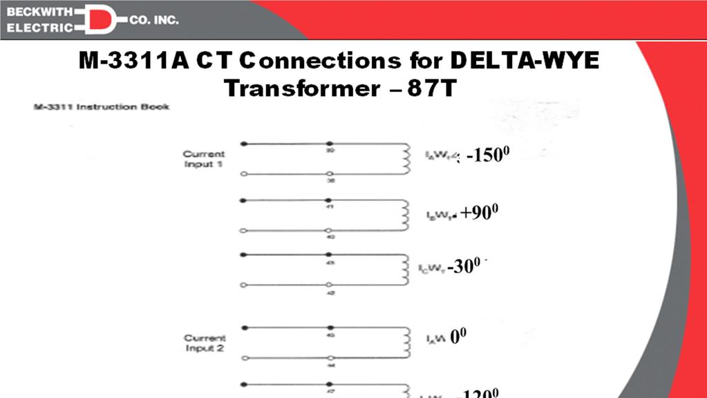
38 M-3311A CT Connections for DELTA-WYE Transformer 87T

39
40 87T TESTING FOR DELTA -WYE TRANSFORMER CONNECTION CHECK FOR PROPER CONNECTIONS. A) APPLY THREE PHASE CURRENTS TO BOTH INPUT 1 = 5.0A and INPUT2 = 5.0A. RELAY SHOULD NOT OPERATE. CHECK PHASE ANGLE METERING SCREEN FOR PROPER PHASING. MINIMUM PICKUP TEST A) SET INPUT 1 CURRENTS = 0 B) HOLD DOWN TARGET RESET BUTTON. SLOWLY INCREASE CURRENTS IN INPUT 2 CURRENTS. THE RELAY WILL OPERATE WHEN CURRENT REACHES 0.25A. ( 1.0A TAP X 0.25 PU). SLOPE 1 TEST A) SET INPUT 1= 1.00 AND INPUT 2 CURRENTS TO 1.0A. B) CALCULATE THE VALUE OF INPUT 2 USING THE BELOW EQUATION WHERE S1 IS THE % SLOPE SETTING. FROM OUR SETTINGS: SLOPE 1 = 30% INPUT 1 = 1.00 INPUT 2 = [ S1 ] = 1.0A [ ] = 1.35A 200 S C) HOLD DOWN TARGET RESET BUTTON AND SLOWLY INCREASE INPUT 2 CURRENTS. LED SHOULD COME ON AT 1.35A.
41 87T TESTING FOR Delta-Wye TRANSFORMER CONNECTION SLOPE 2 TEST A) SET BOTH INPUT 1 = 5.00 A and INPUT 2 CURRENTS TO 5.0A. B) CALCULATE THE VALUE OF INPUT 1 USING THE BELOW EQUATION WHERE S1 AND S2 ARE THE SLOPE SETTING. FROM OUR SETTINGS: SLOPE 1 = 30% SLOPE 2 = 60% BP (BREAK POINT) =2.0 INPUT 2 = [ INPUT 2 (1+S2) + BP ( S1 S2) ] _ 200 _ S2 200 = [ 5.0 ( ) ( 30-60) ] = 8.43A C) HOLD DOWN TARGET RESET BUTTON AND SLOWLY INCREASE INPUT 2 CURRENTS. LED SHOULD COME ON AT 8.43A.
42 Oscillograph Demo


43 Comtrade Format Oscillographs

44 Waveform Capture (Phasor) Phasor diagram with values displayed Phasor display shown at at Marker #1 location Area of current reversal

45 Waveform Capture (Power and Impedance) Waveform Capture (MW-MVAR, R-X) Marker #1 Marker #2 Impedance Values at Marker #1 Impedance Trajectory Over Record Impedance Values at Marker #2 Power Trajectory Over Record Power Value at Marker #1 Power Value at Marker #2


46 3311A TRANSFORMER PROTECTIVE RELAY TEST PLAN THE END????QUESTION????
IMPROVEMENTS IN PROTECTION AND COMMISSIONING OF DIGITAL TRANSFORMER RELAYS AT MEDIUM VOLTAGE INDUSTRIAL FACILITIES
 IMPOVEMENTS IN POTECTION AND COMMISSIONING OF DIGITAL TANSFOME ELAYS AT MEDIUM VOLTAGE INDUSTIAL FACILITIES Copyright Material IEEE Paper No. PCIC-AN84 Charles J. Mozina, P.E. Life Fellow Member, IEEE
Waterpower '97. Upgrading Hydroelectric Generator Protection Using Digital Technology
 Waterpower '97 August 5 8, 1997 Atlanta, GA Upgrading Hydroelectric Generator Protection Using Digital Technology Charles J. Beckwith Electric Company 6190-118th Avenue North Largo, FL 33773-3724 U.S.A.
NERC Requirements for Setting Load-Dependent Power Plant Protection: PRC-025-1
 NERC Requirements for Setting Load-Dependent Power Plant Protection: PRC-025-1 Charles J. Mozina, Consultant Beckwith Electric Co., Inc. www.beckwithelectric.com I. Introduction During the 2003 blackout,
Improving Transformer Protection
 Omaha, NB October 12, 2017 Improving Transformer Protection Wayne Hartmann VP, Customer Excellence Senior Member, IEEE Wayne Hartmann Senior VP, Customer Excellence Speaker Bio whartmann@beckwithelectric.com
Hands On Relay School Open Lecture Transformer Differential Protection Scott Cooper
 Hands On Relay School Open Lecture Transformer Differential Protection Scott Cooper Transformer Differential Protection ntroduction: Transformer differential protection schemes are ubiquitous to almost
Catastrophic Relay Misoperations and Successful Relay Operation
 Catastrophic Relay Misoperations and Successful Relay Operation Steve Turner (Beckwith Electric Co., Inc.) Introduction This paper provides detailed technical analysis of several catastrophic relay misoperations
Advanced Applications of Multifunction Digital Generator Protection
 Advanced Applications of Multifunction Digital Generator Protection Charles J. Mozina Beckwith Electric Company 6190-118th Avenue North Largo, FL 33773-3724 U.S.A. Abstract: The protection of generators
Hands On Relay School Open Lecture Transformer Differential Protection Scott Cooper
 Hands On Relay School Open Lecture Transformer Differential Protection Scott Cooper Transformer Differential Protection ntroduction: Transformer differential protection schemes are ubiquitous to almost
www. ElectricalPartManuals. com Transformer Differential Relay MD32T Transformer Differential Relay
 Transformer Differential Relay The MD3T Transformer Differential Relay is a member of Cooper Power Systems Edison line of microprocessor based protective relays. The MD3T relay offers the following functions:
Transformer Protection
 Transformer Protection Transformer Protection Outline Fuses Protection Example Overcurrent Protection Differential Relaying Current Matching Phase Shift Compensation Tap Changing Under Load Magnetizing
www. ElectricalPartManuals. com Generator Differential Relay MD32G Rotating Machine Differential Relay
 Generator Differential Relay The MD3G Rotating Machine Differential Relay is a member of Cooper Power Systems Edison line of microprocessor based protective relays. The MD3G relay offers the following
Tom Ernst GE Digital Energy Craig Talbot Minnesota Power
 Tom Ernst GE Digital Energy Craig Talbot Minnesota Power Introduction Traditional 3-phase testing method Traditional 1-phase testing method Alternate 1-phase testing method Application examples 3-Phase
NO WARRANTIES OF ANY KIND ARE IMPLIED ON THE INFORMATION CONTAINED IN THIS DOCUMENT.
 MODBUS/BECO2200-M3425A Communication Data Base for M-3425A Integrated Protection System Device I.D. = 150 Specifications presented herein are thought to be accurate at the time of publication but are subject
Transformer Protection
 1 Presenter Contact Info Wayne Hartmann Senior VP, Customer Excellence Beckwith Electric Company whartmann@beckwithelectric.com 904 238 3844 Wayne is the top strategist for delivering innovative technology
Testing Numerical Transformer Differential Relays
 Feature Testing Numerical Transformer Differential Relays Steve Turner Beckwith Electric Co., nc. ntroduction Numerical transformer differential relays require careful consideration as to how to test properly.
Pinhook 500kV Transformer Neutral CT Saturation
 Russell W. Patterson Tennessee Valley Authority Presented to the 9th Annual Fault and Disturbance Analysis Conference May 1-2, 26 Abstract This paper discusses the saturation of a 5kV neutral CT upon energization
Generator Protection GENERATOR CONTROL AND PROTECTION
 Generator Protection Generator Protection Introduction Device Numbers Symmetrical Components Fault Current Behavior Generator Grounding Stator Phase Fault (87G) Field Ground Fault (64F) Stator Ground Fault
Verifying Transformer Differential Compensation Settings
 Verifying Transformer Differential Compensation Settings Edsel Atienza and Marion Cooper Schweitzer Engineering Laboratories, Inc. Presented at the 6th International Conference on Large Power Transformers
Generator Protection M 3420
 PROTECTION Generator Protection M 3420 Integrated Protection System for Generators of All Sizes Unit shown with optional M 3920 Target Module and M 3931 HMI (Human-Machine Interface) Module Microprocessor-based
Transformer Protection Principles
 Transformer Protection Principles 1. Introduction Transformers are a critical and expensive component of the power system. Due to the long lead time for repair of and replacement of transformers, a major
Generator Protection M 3425
 PROTECTION Generator Protection M 3425 Integrated Protection System for Generators of All Sizes Unit shown with optional M 3925 Target Module and M 3931 HMI (Human Machine Interface) Module Provides all
This webinar brought to you by The Relion Product Family Next Generation Protection and Control IEDs from ABB
 This webinar brought to you by The Relion Product Family Next Generation Protection and Control IEDs from ABB Relion. Thinking beyond the box. Designed to seamlessly consolidate functions, Relion relays
Impact Assessment Generator Form
 Impact Assessment Generator Form This connection impact assessment form provides information for the Connection Assessment and Connection Cost Estimate. Date: (dd/mm/yyyy) Consultant/Developer Name: Project
Transformer protection IED RET 670
 Gunnar Stranne Transformer protection IED RET 670 Santiago Septiembre 5, 2006 1 Transformer protection IED RET670 2 Introduction features and applications Differential protection functions Restricted Earth
PROTECTIVE RELAY MISOPERATIONS AND ANALYSIS
 PROTECTIVE RELAY MISOPERATIONS AND ANALYSIS BY STEVE TURNER, Beckwith Electric Company, Inc. This paper provides detailed technical analysis of two relay misoperations and demonstrates how to prevent them
Multimeter 500CVD21 RTU500 series
 Remote Terminal Units - Data sheet Multimeter 500CVD21 RTU500 series CT/VT interface with 4 voltage and 24 current inputs for direct monitoring of 3/4 wire 0 300 V AC (line to earth), 0...500 V AC (phase
This webinar brought to you by the Relion product family Advanced protection and control IEDs from ABB
 This webinar brought to you by the Relion product family Advanced protection and control IEDs from ABB Relion. Thinking beyond the box. Designed to seamlessly consolidate functions, Relion relays are smarter,
Instruction Book. M 3425A Generator Protection
 Instruction Book M 3425A Generator Protection TRADEMARKS All brand or product names referenced in this document may be trademarks or registered trademarks of their respective holders. The content of this
g GE POWER MANAGEMENT
 745 FREQUENTLY ASKED QUESTIONS 1 I get a communication error with the relay when I try to store a setpoint. This error can occur for several different reasons. First of all, verify that the address is
889 Advanced Generator Protection Technical Note
 GE Grid Solutions 8 Series 889 Advanced Generator Protection Technical Note GE Publication Number: GET-20056 Copyright 2017 GE Multilin Inc. Overview The Multilin 889 is part of the 8 Series platform that
Transformer Protection
 Transformer Protection Nature of transformer faults TXs, being static, totally enclosed and oil immersed develop faults only rarely but consequences large. Three main classes of faults. 1) Faults in Auxiliary
ENOSERV 2014 Relay & Protection Training Conference Course Descriptions
 ENOSERV 2014 Relay & Protection Training Conference Course Descriptions Day 1 Generation Protection/Motor Bus Transfer Generator Protection: 4 hours This session highlights MV generator protection and
Differential Protection with REF 542plus Feeder Terminal
 Differential Protection with REF 542plus Application and Setting Guide kansikuva_bw 1MRS 756281 Issued: 09.01.2007 Version: A Differential Protection with REF 542plus Application and Setting Guide Contents:
MICROPROCESSOR-BASED METERING EQUIPMENT SECTION 16901C PART 2
 PART 1 PART 2 PRODUCTS 2.01 MANUFACTURERS A. Eaton products B.. C.. The listing of specific manufacturers above does not imply acceptance of their products that do not meet the specified ratings, features
Relay-assisted commissioning
 Relay-assisted commissioning by Casper Labuschagne and Normann Fischer, Schweitzer Engineering Laboratories (SEL) Power transformer differential relays were among the first protection relays to use digital
Performance Analysis of Traditional and Improved Transformer Differential Protective Relays
 Performance Analysis of Traditional and Improved Transformer Differential Protective Relays Armando Guzmán, Stan Zocholl, and Gabriel Benmouyal Schweitzer Engineering Laboratories, Inc. Hector J. Altuve
Problems connected with Commissioning of Power Transformers
 Problems connected with Commissioning of Power Transformers ABSTRACT P Ramachandran ABB India Ltd, Vadodara, India While commissioning large Power Transformers, certain abnormal phenomena were noticed.
INSTRUCTION MANUAL TRANSFORMER PROTECTION RELAY GRT100 - B
 INSTRUCTION MANUAL TRANSFORMER PROTECTION RELAY GRT00 - B Toshiba Energy Systems & Solutions Corporation 207 All Rights Reserved. ( Ver. 3.) Safety Precautions Before using this product, be sure to read
STRAY FLUX AND ITS INFLUENCE ON PROTECTION RELAYS
 1 STRAY FLUX AND ITS INFLUENCE ON PROTECTION RELAYS Z. GAJIĆ S. HOLST D. BONMANN D. BAARS ABB AB, SA Products ABB AB, SA Products ABB AG, Transformers ELEQ bv Sweden Sweden Germany Netherlands zoran.gajic@se.abb.com
Transformer Differential Protection Lab
 Montana Tech Library Digital Commons @ Montana Tech Proceedings of the Annual Montana Tech Electrical and General Engineering Symposium Student Scholarship 2016 Transformer Differential Protection Lab
A Tutorial on the Application and Setting of Collector Feeder Overcurrent Relays at Wind Electric Plants
 A Tutorial on the Application and Setting of Collector Feeder Overcurrent Relays at Wind Electric Plants Martin Best and Stephanie Mercer, UC Synergetic, LLC Abstract Wind generating plants employ several
Transformer Protection M-3311A
 PROTECTON Transformer Protection ntegrated Protection System Unit shown with optional M-3931 HM Module and M-3911 Target Module For Transformers of All Sizes: 2, 3 or 4 winding Transformers for Transmission
Solution for Effect of Zero Sequence Currents on Y-Y Transformer Differential Protection
 ABSTRACT National conference on Engineering Innovations and Solutions (NCEIS 2018) International Journal of Scientific Research in Computer Science, Engineering and Information Technology 2018 IJSRCSEIT
Substation Testing and Commissioning: Power Transformer Through Fault Test
 1 Substation Testing and Commissioning: Power Transformer Through Fault Test M. Talebi, Member, IEEE, Power Grid Engineering Y. Unludag Electric Power System Abstract This paper reviews the advantage of
BE1-67N GROUND DIRECTIONAL OVERCURRENT RELAY FEATURES ADDITIONAL INFORMATION. FUNCTIONS AND FEATURES Pages 2-4. APPLICATIONS Page 2
 BE1-67N GROUND DIRECTIONAL OVERCURRENT RELAY The BE1-67N Ground Directional Overcurrent Relay provides ground fault protection for transmission and distribution lines by sensing the direction and magnitude
Multi Differential Relay, MDR-2 DESCRIPTION OF OPTIONS
 Multi Differential Relay, MDR-2 DESCRIPTION OF OPTIONS Option C4 Block differential current protection Description of option Functional descriptions Parameter list Document no.: 4189340397C SW version:
GENERATOR INTERCONNECTION APPLICATION Category 5 For All Projects with Aggregate Generator Output of More Than 2 MW
 GENERATOR INTERCONNECTION APPLICATION Category 5 For All Projects with Aggregate Generator Output of More Than 2 MW ELECTRIC UTILITY CONTACT INFORMATION Consumers Energy Interconnection Coordinator 1945
Forward to the Basics: Selected Topics in Distribution Protection
 Forward to the Basics: Selected Topics in Distribution Protection Lee Underwood and David Costello Schweitzer Engineering Laboratories, Inc. Presented at the IEEE Rural Electric Power Conference Orlando,
Protection of a 138/34.5 kv transformer using SEL relay
 Scholars' Mine Masters Theses Student Theses and Dissertations Fall 2016 Protection of a 138/34.5 kv transformer using SEL 387-6 relay Aamani Lakkaraju Follow this and additional works at: http://scholarsmine.mst.edu/masters_theses
Babak Enayati National Grid Thursday, April 17
 2014 IEEE PES Transmission & Distribution Conference & Exposition Impacts of the Distribution System Renewable Energy Resources on the Power System Protection Babak Enayati National Grid Thursday, April
Phase Shifting Transformers. Presented by
 Phase Shifting Transformers Presented by Phase Shifting Transformers (PST s) (a.k.a. Phase Angle Regulators) VS φ S P V V S = X L L X L sin( φ φ ) L S VL φ L PST s are power flow control devices between
Focused Directional Overcurrent Elements (67P, Q and N) for DER Interconnection Protection
 for DER Interconnection Protection") Engineered Solutions for Power System Protection, Automaton and Control APPLICATION NOTE Focused Directional Overcurrent Elements (67P, Q and N) for DER Interconnection Protection 180622 Abstract This
Engineered Solutions for Power System Protection, Automaton and Control APPLICATION NOTE Focused Directional Overcurrent Elements (67P, Q and N) for DER Interconnection Protection 180622 Abstract This
EASUN REYROLLE LIMITED
 OCTOBER 2003 APPLICATION AND COMMISSIONING MANUAL FOR NUMERICAL BIASED DIFFERENTIAL PROTECTION RELAY TYPE - MIB202 EASUN REYROLLE LIMITED 1 ISSUE NO : 1 st Issue DATE OF ISSUE : 01-10 - 2003 DEPARTMENT
Power System Protection. Dr. Lionel R. Orama Exclusa, PE Week 3
 Power System Protection Dr. Lionel R. Orama Exclusa, PE Week 3 Operating Principles: Electromagnetic Attraction Relays Readings-Mason Chapters & 3 Operating quantities Electromagnetic attraction Response
COPYRIGHTED MATERIAL. Index
 Index Note: Bold italic type refers to entries in the Table of Contents, refers to a Standard Title and Reference number and # refers to a specific standard within the buff book 91, 40, 48* 100, 8, 22*,
Differential Protection Optimal differential protection for phase shifter transformers and special transformers
 Differential Protection Optimal differential protection for phase shifter transformers and special transformers Due to the energy transition, a demand for renewable energy sources integration into power
Evaluating the Impact of Increasing System Fault Currents on Protection
 Evaluating the Impact of Increasing System Fault Currents on Protection Zhihan Xu, Ilia Voloh GE Grid Solutions, LLC Mohsen Khanbeigi Hydro One Abstract Every year the capacity of power systems is increasing,
O V E R V I E W O F T H E
 A CABLE Technicians TESTING Approach to Generator STANDARDS: Protection O V E R V I E W O F T H E 1 Moderator n Ron Spataro AVO Training Institute Marketing Manager 2 Q&A n Send us your questions and comments
Instruction Book. M-3425A Generator Protection
 Instruction Book M-3425A Generator Protection PROTECTION Generator Protection M 3425A Integrated Protection System for Generators of All Sizes Unit shown with optional M 3925A Target Module and M 3931
Impact of Incipient Faults on Sensitive Protection
 Impact of Incipient Faults on Sensitive Protection Paper Authors: Ilia Voloh GE Grid Solutions Zhihan Xu, Ilia Voloh GE Grid Solutions Leonardo Torelli CSE-Uniserve Presented by: Tom Ernst GE Grid Solutions
POWER SYSTEM ANALYSIS TADP 641 SETTING OF OVERCURRENT RELAYS
 POWER SYSTEM ANALYSIS TADP 641 SETTING OF OVERCURRENT RELAYS Juan Manuel Gers, PhD Protection coordination principles Relay coordination is the process of selecting settings that will assure that the relays
M 7679 R-PAC. Protection, Automation and Control System for Recloser, Switch, Sectionalizer and Advanced Distribution Automation Applications
 M 7679 R-PAC Protection, Automation and Control System for Recloser, Switch, Sectionalizer and Advanced Distribution Automation Applications Protection and Control Over 30 Protection Elements for optimal
International Journal of Advance Engineering and Research Development ANALYSIS OF INTERNAL AND EXTERNAL FAULT FOR STAR DELTA TRANSFORMER USING PSCAD
 Scientific Journal of Impact Factor(SJIF): 3.134 International Journal of Advance Engineering and Research Development Volume 2,Issue 6, June -2015 e-issn(o): 2348-4470 p-issn(p): 2348-6406 ANALYSIS OF
Overcurrent Elements
 Exercise Objectives Hands-On Relay Testing Session Overcurrent Elements After completing this exercise, you should be able to do the following: Identify overcurrent element settings. Determine effective
NEW DESIGN OF GROUND FAULT PROTECTION
 NEW DESIGN OF GROUND FAULT PROTECTION J. Blumschein*, Y. Yelgin* *SIEMENS AG, Germany, email: joerg.blumschein@siemens.com Keywords: Ground fault protection, directional element, faulted phase selection
Embedded Generation Connection Application Form
 Embedded Generation Connection Application Form This Application Form provides information required for an initial assessment of the Embedded Generation project. All applicable sections must be completed
Using a Multiple Analog Input Distance Relay as a DFR
 Using a Multiple Analog Input Distance Relay as a DFR Dennis Denison Senior Transmission Specialist Entergy Rich Hunt, M.S., P.E. Senior Field Application Engineer NxtPhase T&D Corporation Presented at
Distance Relay Response to Transformer Energization: Problems and Solutions
 1 Distance Relay Response to Transformer Energization: Problems and Solutions Joe Mooney, P.E. and Satish Samineni, Schweitzer Engineering Laboratories Abstract Modern distance relays use various filtering
Course ELEC Introduction to electric power and energy systems. Additional exercises with answers December reactive power compensation
 Course ELEC0014 - Introduction to electric power and energy systems Additional exercises with answers December 2017 Exercise A1 Consider the system represented in the figure below. The four transmission
Detecting and Managing Geomagnetically Induced Currents With Relays
 Detecting and Managing Geomagnetically Induced Currents With Relays Copyright SEL 2013 Transformer Relay Connections Voltage Current Control RTDs Transformer Protective Relay Measures differential current
Rarely used, problems with unbalanced loads.
 THREE-PHASE TRANSFORMERS Transformers used in three-phase systems may consist of a bank of three single-phase transformers or a single three-phase transformer which is wound on a common magnetic core.
DIFFERENTIAL PROTECTION METHODOLOGY FOR ARBITRARY THREE-PHASE POWER TRANSFORMERS
 DFFERENTAL PROTECTON METHODOLOGY FOR ARBTRARY THREE-PHASE POWER TRANSFORMERS Z. Gaji ABB AB-SA Products, Sweden; zoran.gajic@se.abb.com Keywords: power transformer, phase shifting transformer, converter
Generator Protection M 3425A
 PROTECTION Generator Protection M 3425A Integrated Protection System for Generators of All Sizes Unit shown with optional M 3925A Target Module and M 3931 HMI (Human Machine Interface) Module Exceeds IEEE
OPEN-PHASE DETECTION TECHNIQUES FOR CRITICAL STANDBY SUPPLIES
 OPEN-PHASE DETECTION TECHNIQUES FOR CRITICAL STANDBY SUPPLIES U AJMAL, GE Grid Solutions UK Ltd, usman.ajmal@ge.com S SUBRAMANIAN, GE Grid Solutions UK Ltd, sankara.subramanian@ge.com H Ha GE Grid Solutions
ANALYSIS OF A DIFFERENTIAL AND OVERCURRENT OPERATION ON A 345KV HIGH VOLTAGE LINE REACTOR
 ANALYSIS OF A DIFFERENTIAL AND OVERCURRENT OPERATION ON A 345KV HIGH VOLTAGE LINE REACTOR Authors: Eric Schroeder P.E., Cross Texas Transmission, Amarillo, Texas Jerry Burton, Cross Texas Transmission,
PD300. Transformer, generator and motor protection Data sheet
 PD300 Transformer, generator and motor protection Data sheet DSE_PD300_eng_AO No part of this publication may be reproduced by whatever means without the prior written permission of Ingeteam T&D. One of
148 Electric Machines
 148 Electric Machines 3.1 The emf per turn for a single-phase 2200/220- V, 50-Hz transformer is approximately 12 V. Calculate (a) the number of primary and secondary turns, and (b) the net cross-sectional
86 chapter 2 Transformers
 86 chapter 2 Transformers Wb 1.2x10 3 0 1/60 2/60 3/60 4/60 5/60 6/60 t (sec) 1.2x10 3 FIGURE P2.2 2.3 A single-phase transformer has 800 turns on the primary winding and 400 turns on the secondary winding.
Embedded Generation Connection Application Form
 Embedded Generation Connection Application Form This Application Form provides information required for an initial assessment of the Embedded Generation project. All applicable sections must be completed
Minnesota Power Systems Conference 2015 Improving System Protection Reliability and Security
 Minnesota Power Systems Conference 2015 Improving System Protection Reliability and Security Steve Turner Senior Application Engineer Beckwith Electric Company Introduction Summarize conclusions from NERC
TheRelayTestingHandbook
 TheRelayTestingHandbook PrinciplesandPractice ProfessionalEngineer JourneymanPowerSystem Electrician ElectricalEngineeringTechnologist Table of Contents Author s Note Acknowledgments v vii Chapter 1: Electrical
Stabilized Differential Relay SPAD 346. Product Guide
 Issued: July 1998 Status: Updated Version: D/21.03.2006 Data subject to change without notice Features Integrated three-phase differential relay, three-phase overcurrent relay and multiconfigurable earth-fault
489 Generator Management Relay
 GE Digital Energy 489 Generator Management Relay SELECT CURVE STYLE: Voltage Dependent 489 STATUS GENERATOR STATUS OUTPUT RELAYS 489 IN SERVICE BREAKER OPEN R1 TRIP SETPOINT ACCESS BREAKER CLOSED R2 AUXILIARY
Relaying 101. by: Tom Ernst GE Grid Solutions
 Relaying 101 by: Tom Ernst GE Grid Solutions Thomas.ernst@ge.com Relaying 101 The abridged edition Too Much to Cover Power system theory review Phasor domain representation of sinusoidal waveforms 1-phase
Keywords: Wavelet packet transform (WPT), Differential Protection, Inrush current, CT saturation.
, Differential Protection, Inrush current, CT saturation.") IJESRT INTERNATIONAL JOURNAL OF ENGINEERING SCIENCES & RESEARCH TECHNOLOGY Differential Protection of Three Phase Power Transformer Using Wavelet Packet Transform Jitendra Singh Chandra*, Amit Goswami
IJESRT INTERNATIONAL JOURNAL OF ENGINEERING SCIENCES & RESEARCH TECHNOLOGY Differential Protection of Three Phase Power Transformer Using Wavelet Packet Transform Jitendra Singh Chandra*, Amit Goswami
Turn-to-Turn Fault Detection in Transformers Using Negative Sequence Currents
 Turn-to-Turn Fault Detection in Transformers Using Negative Sequence Currents Mariya Babiy 1, Rama Gokaraju 1, Juan Carlos Garcia 2 1 University of Saskatchewan, Saskatoon, Canada 2 Manitoba HVDC Research
Visualization and Animation of Protective Relay Operation
 Visualization and Animation of Protective Relay Operation A. P. Sakis Meliopoulos School of Electrical and Computer Engineering Georgia Institute of Technology Atlanta, Georgia 30332 George J. Cokkinides
Embedded Generation Connection Application Form
 Embedded Generation Connection Application Form This Application Form provides information required for an initial assessment of the Embedded Generation project. All applicable sections must be completed
Hands-On-Relay School 2015 Distribution Event Analysis. Randy Spacek Protection Engineer Manager
 Hands-On-Relay School 2015 Distribution Event Analysis Randy Spacek Protection Engineer Manager OVERVIEW Available Tools Fault Type Identification: line and transformer Relay Event Record: Oscillography
Smart Busbar Protection Based ANFIS Technique for Substations and Power Plants
 Smart Busbar Protection Based ANFIS Technique for Substations and Power Plants 1 Mohamed A. Ali, 2 Sayed A. Ward, 3 Mohamed S. Elkhalafy 123 Faculty of Engineering Shoubra, Benha University Email: 1 mohamed.mohamed02@feng.bu.edu.eg,
NTG MULTIFUNCTON GENERATOR PROTECTION RELAY. NTG-Slide
 NTG MULTIFUNCTON GENERATOR PROTECTION RELAY 1 NTG Digital protection relay that integrates a number of functions required r for the protection of generators. It is used in power stations from gas, steam,
489 Generator Management Relay Instruction Manual
 Digital Energy Multilin Firmware Revision: 4.0X Manual Part Number: 1601-0150-AF Manual Order Code: GEK-106494P Copyright 2011 GE Multilin 489 Generator Management Relay Instruction Manual GE Multilin
Performance Evaluation of Generator- Transformer Unit Overall Differential Protection in Large Power Plant
 Performance Evaluation of Generator- Transformer Unit Overall Differential Protection in Large Power Plant Wael Yousef, IEEE Senior Member Mahmoud A. Elsadd Almoataz Y. Abdelaziz, IEEE Senior Member Mohamed
489 Generator Management Relay
 GE Grid Solutions 489 Generator Management Relay Instruction Manual Product version: 4.0x GE publication code: 1601-0150-AM (GEK-106494W) 1601-0150-AM Copyright 2016 GE Multilin Inc. All rights reserved.
Code No: R Set No. 1
 Code No: R05220204 Set No. 1 II B.Tech II Semester Supplimentary Examinations, Aug/Sep 2007 ELECTRICAL MACHINES-II (Electrical & Electronic Engineering) Time: 3 hours Max Marks: 80 Answer any FIVE Questions
ATP modeling of internal transformer faults for relay performance testing
 Michigan Technological University Digital Commons @ Michigan Tech Dissertations, Master's Theses and Master's Reports - Open Dissertations, Master's Theses and Master's Reports 2011 ATP modeling of internal
Impacts of the Renewable Energy Resources on the Power System Protection by: Brent M. Fedele, P.E., National Grid for: 11 th Annual CNY Engineering
 Impacts of the Renewable Energy Resources on the Power System Protection by: Brent M. Fedele, P.E., National Grid for: 11 th Annual CNY Engineering Expo - Nov. 3, 2014 Index Normal Distribution System
Evaluating the Impact of Increasing System Fault Currents on Protection
 Evaluating the Impact of Increasing System Fault Currents on Protection Ilia Voloh, Zhihan Xu GE Grid Solutions Mohsen Khanbeigi Hydro One 7th Annual Conference for Protective Relay Engineers Outline Overview
System Protection and Control Subcommittee
 Power Plant and Transmission System Protection Coordination Reverse Power (32), Negative Sequence Current (46), Inadvertent Energizing (50/27), Stator Ground Fault (59GN/27TH), Generator Differential (87G),
Connection Impact Assessment Application
 Connection Impact Assessment Application This form is for generators applying for Connection Impact Assessment (CIA) and for generators with a project size >10 kw. Please return the completed form by email,