PD300. Transformer, generator and motor protection Data sheet
|
|
|
- Juliana Farmer
- 5 years ago
- Views:
Transcription

1 PD300 Transformer, generator and motor protection Data sheet
2 DSE_PD300_eng_AO No part of this publication may be reproduced by whatever means without the prior written permission of Ingeteam T&D. One of the main aims of Ingeteam T&D lies in the continuous improvement of the company s equipment and, therefore, the information contained in this catalogue may be modified without prior notification. For further information, consult the corresponding manual or contact us directly.
3 INDEX MODEL CODE SELECTION... 4 FUNCTIONS TABLE... 5 FUNCTIONAL DESCRIPTION AND CONFIGURATION... 6 General settings... 6 Protection settings... 6 AUTOMATISM FUNCTIONS DATA ACQUISITION MEASUREMENTS COMMUNICATION PROTOCOLS KEYPAD/LOCAL DISPLAY TESTS TECHNICAL SPECIFICATIONS ENVIRONMENTAL CONDITIONS CONSTRUCTION FEATURES CONNECTION DIAGRAMS DSE_PD300_eng III
4 MODEL CODE SELECTION DSE_PD300_eng 4
5 FUNCTIONS TABLE PD300-2 PD300-3 PD300-G Protection functions Overexcitation (24) 5th harmonic or V/Hz 2 units. 5th harmonic 5th harmonic Undervoltage (27) X X Current unbalance (46) X X X Thermal image (49) X X X Instantaneous phase overcurrent (50) 2 units in each winding 2 units in each winding 2 units in each winding Time phase overcurrent (51) 1 unit in each winding 1 unit in each winding 1 unit in each winding Residual instantaneous overcurrent (50R) 2 units in each winding 2 units in each winding 2 units in each winding Residual time overcurrent (51R) 1 unit in each winding 1 unit in each winding 1 unit in each winding Instantaneous ground overcurrent (50G) 2 units in each winding 2 units in each winding Time ground overcurrent (51G) 1 unit in each winding 1 unit in each winding Breaker failure (50BF) X X X Overvoltage (59) X Xº Overfrequency (81M) 5 steps 5 steps Underfrequency (81m) 5 steps 5 steps Differential (87) In percentage and In percentage and In percentage and instantaneous instantaneous instantaneous Restricted earth (87G) X X Breaker monitoring X X X Trip and closure circuit surveillance (74TC/CC) X X X Power supply monitoring O O O External power supply monitoring O O O Temperature monitoring X X X Automatisms and commands Breaker and closure commands X X X Programmable logic X X X Breaker closure lock (86) X X X Note: X: Available function O: Optional function DSE_PD300_eng 5
6 FUNCTIONAL DESCRIPTION AND CONFIGURATION GENERAL SETTINGS Setting Minimum Maximum Step Remarks Relay in operation Breaker number 5 alphanum. characters PROTECTION SETTINGS Differential protection (87) Three-phase differential unit. Numeric ratio and connection group correction. Zero sequence component filter: Enables the elimination of the phase currents zero sequence component. Adjustable differential current instantaneous trip. 2nd, 2nd + 4th and 5th harmonic restraint, adjustable (Not available for PD300-G). Cross blocking (except in PD300-G). General settings Minimum Maximum Step Remarks Rated voltage winding 1(kV) ,1 Rated voltage winding 2(kV) ,1 Rated voltage winding 3(kV) ,1 C.T. ratio winding ,1 C.T. ratio winding ,1 C.T. ratio winding ,1 Connection type winding 1/2/3 Y/D/Z Phase shift Phase shift Function 86 enabled Grounding 1 C.T. ratio ,1 Grounding 2 C.T. ratio ,1 VT ratio ,1 Maximum power capacity (MVA) 0, ,1 Tap winding 1 0, ,01 In = 5A 0,1 20 0,01 In = 1A and PD300-G Tap winding 2 0, ,01 In = 5A 0,1 20 0,01 In = 1A and PD300-G Tap winding 3 0, ,01 In = 5A 0,1 20 0,01 In = 1A Differential 2/3 windings 2wind. /3wind. Percentage charact. setting Minimum Maximum Step Remarks Sensitivity (xtap) 0,15 2 0,01 Restraint current 1 (xtap) 0 2 0,01 Restraint current 2 (xtap) ,01 α1 (%) α2 (%) Additional delay (s) ,01 DSE_PD300_eng 6
7 Instantaneous differential setting Minimum Maximum Step Remarks Trip (xtap) for PD300-2 and PD ,0 20 0,01 Trip (xtap) for PD300-G 0,60 4,00 0,01 Additional delay (s) ,01 Harmonic restraint setting (disabled for PD300-G) Minimum Maximum Step Remarks 2nd harmonic restraint enabled NO / 2nd PHASE / 2nd GLOBAL/ 2nd+4th PHASE / 2nd+4th GLOBAL 2nd harmonic restraint threshold (%) Differential threshold (xtap) 0,15 1 0,01 5th harmonic restraint enabled NO / PHASE / GLOBAL 5th harmonic restraint threshold (%) Differential threshold (xtap) 0,15 1 0,01 Restricted earth (87G) - Models PD300-2 and PD300-G This function is applicable when one of the transformer s windings is grounded. The function compares the residual current with the current flowing through the grounded transformer. Should the difference between both currents, following the application of the corresponding transformation ratios, exceed the set threshold, a trip signal is issued. The direction is taken into account when allowing the trip. Setting Minimum Maximum Step Remarks Pick up (A) 0,25 0, ,01 0,01 In = 5 A In = 1 A and Generator and motor Additional time (s) ,01 Winding comparison Wind. 1, Wind. 2 or Autotransformer Phase overcurrent protection (50/51) - All models A back-up protection for external or internal transformer faults. In the event of such faults not being cleared by the primary protections, the overcurrent protection acts. Serious damage to the transformer would be produced in the absence of such protection. Each winding is equipped with two instantaneous levels and one timed level. Time charactistic setting (6 groups) Minimum Maximum Step Remarks Pick up (A) 0,1 160,0 0,01 In = 5 A 0,02 32,0 0,01 In = 1A and PD300-G Definite time (TF) Curve type Inverse curve, very inverse, extremely inverse User curves Dial 0,05 1,09 0,01 For IEC curves 0,5 30,0 0,1 For ANSI curves Definite delay (s) 0,0 600,0 0,01 Instantaneous charactistic setting (low-level - 6 groups) Minimum Maximum Step Remarks Pick up (A) 0,1 160,0 0,01 In = 5 A 0,02 32,0 0,01 In = 1A and PD300-G Additional delay (s) 0,00 60,00 0,01 DSE_PD300_eng 7
8 Instantaneous characteristic setting (high-level - -6 groups) Minimum Maximum Step Remarks Pick up (A) 0,1 160,0 0,01 In = 5 A 0,02 32,0 0,01 In = 1A and PD300-G Additional delay (s) 0,00 60,00 0,01 Residual overcurrent protection (50/51R) - All models An overcurrent function that is applied to the directional sum of the three phases in order to detect earth faults. It is equipped with independent units for each of the windings. Time characteristic settings (6 groups) Minimum Maximum Step Remarks Pick up (A) 0,2 160,0 0,01 In = 5 A 0,05 32,0 0,01 In = 1A and PD300-G Definite time (TF) Curve type Inverse curve, very inverse, extremely inverse User curves Dial 0,05 1,09 0,01 For IEC curves 0,5 30,0 0,1 For ANSI curves Definite delay (s) 0,0 600,0 0,01 Instantaneous characteristic settings (low-level -6 groups) Minimum Maximum Step Remarks Pick up (A) 0,2 160,0 0,01 In = 5 A 0,05 32,0 0,01 In = 1A and PD300-G Additional delay (s) 0,0 60,00 0,01 Instantaneous characteristic settings (high-level -6 groups) Minimum Maximum Step Remarks Pick up (A) 0,2 160,0 0,01 In = 5 A 0,05 32,0 0,01 In = 1A and PD300-G Additional delay (s) 0,0 60,00 0,01 Current unbalance protection (46) - All models Protects the installation against current unbalances that occur as a consequence of anomalies in the power system, or against unbalanced loads. It is equipped with independent units for each of the windings. Time charactieristic setting (6 groups) Minimum Maximum Step Remarks Pick up (A) 0,2 160,0 0,01 In = 5 A 0,05 32,0 0,01 In = 1A and PD300-G Definite time (TF) Curve type Inverse curve, very inverse, extremely inverse User curves Dial 0,05 1,09 0,01 For IEC curves 0,5 30,0 0,1 For ANSI curves Definite time (s) 0,0 600,0 0,01 Instantaneous charactistic setting (6 groups) Minimum Maximum Step Remarks Pick up (A) 0,2 160,0 0,01 In = 5 A 0,05 32,0 0,01 In = 1A and PD300-G Additional delay (s) 0,0 60,00 0,01 DSE_PD300_eng 8
9 Earth overcurrent protection (50/51G) - Models PD300-2 and PD300-G Is applied to the power transformer s grounding in order to detect earth faults. It may also be applied as a tank protection. Timed charactistic settings (6 groups) Minimum Maximum Step Remarks /Pickup/YES+Drop-out Pick up (A) 0,1 160,0 0,01 In = 5 A 0,02 32,0 0,01 In = 1A and PD300-G Definite time (TF) Curve type Inverse curve, very inverse, extremely inverse User curves Dial 0,05 1,09 0,01 For IEC curves 0,5 30,0 0,1 For ANSI curves Definite time (s) 0,0 600,0 0,01 Delay if TF type Instantaneous charactistic setting Low-level (6 groups) Minimum Maximum Step Remarks / Pickup Pick up (A) 0,1 160,0 0,01 In = 5 A 0,02 32,0 0,01 In = 1A and PD300-G Additional delay (s) 0,00 60,00 0,01 High level instantaneous characteristic settings (6 groups) Minimum Maximum Step Remarks / Pickup Pick up (A) 0,1 160,0 0,01 In = 5 A 0,02 32,0 0,01 In = 1A and PD300-G Additional delay (s) 0,00 60,00 0,01 Overvoltage protection (59) - Models PD300-2 and PD300-G This function protects the transformer against overvoltages, issuing a trip command when the voltage exceeds the set value during a set period. Time charactistic setting (6 groups) Minimum Maximum Step Remarks Pick up (V) ,1 Curve type Definite time (TF) Inverse curve, very inverse, extremely inverse User curves Dial 0,05 1,09 0,01 For IEC curves 0,5 30,0 0,1 For ANSI curves Definite time (s) 0,0 600,0 0,01 Instantaneous charactic setting (6 groups) Minimum Minimum Step Remarks Pick up (V) ,1 Additional delay (s) 0,00 60,00 0,01 DSE_PD300_eng 9
10 Undervoltage protection (27) - Models PD300-2 and PD300-G Undervoltage may occur in the system during faults or similar situations. Time charactistic settings (6 groups) Minimum Maximum Step Remarks Pick up (A) ,1 Curve type Dial 0,05 0,5 1,09 30,0 0,01 Definite time (s) 0,0 600,0 0,01 0,1 Definite time (TF) Inverse curve, very inverse, extremely inverse User curves For IEC curves For ANSI curves Instantaneous charactistic setting (6 groups) Minimum Maximum Step Remarks Pick up (V) ,1 Additional delay (s) 0,00 60,00 0,01 Overexcitation protection (24) - All models This function prevents the transformers from working at a flux density higher to that for which they have been designed, thus avoiding overheating and the subsequent damage to the transformer resulting from overexcitation. It can be detected through 5 th harmonic current level or through the V/f ratio. 5 th harmonic setting Minimum Maximum Step Remarks Minimum operating current 0, ,01 In = 5 A 0,1 2 0,01 In = 1A and PD300-G Pick-up (%) Additional delay (sec) ,01 Setting for V/f (not available for PD300-3) Minimum Maximum Step Remarks Minimum monitoring voltage (V) Pick up (V/Hz) 1,00 4,00 0,01 Definite time (TF) Curve type Inverse curve, very inverse, extremely inverse User curves Dial 0,05 1,09 0,01 For IEC curves 0,5 30,0 0,1 For ANSI curves Definite time (s) ,01 Frequency protection (81M/m) - Models PD300-2 and PD300-G The frequency unit provides protection against overexcitation. It may also be employed in subfrequency load-shedding schemes, assisting operation in the event of network instability, for which there are 5 steps. The settings, which are independent for each step, are individualized for each step (6 groups): Minimum Maximum Step Remarks Pick up (Hz) ,01 Additional delay (s) 0 600,00 0,01 Type Maximum/Minimum DSE_PD300_eng 10
11 The common settings for all steps are as follows: Setting Minimum Maximum Step Remarks Minimum monitoring voltage (V) Nº of frequency pick-up cycles Thermal image (49) All models Protects the unit against thermal overloads by calculating the temperature in accordance with the protected unit s current and recent load conditions. Setting Minimum Maximum Step Remarks Heating time constant (min) Cooling time constant (min) Alarm threshold (%) Rated current (A) 0,2 0,04 0,04 10,0 2 10,0 0,01 0,01 0,01 In = 5A In = 1A PD300-G Breaker failure protection (50BFI) - All models Verifies the correct operation of a breaker when clearing a fault. In case of an operation failure, the protection trips the adjacent breakers involved in the isolation of the area in fault. Setting Minimum Maximum Step Remarks Phase restoration (A) 0,1 160,0 0,01 In = 5 A 0,02 32,0 0,01 In = 1A and PD300-G Neutral restoration (A) 0,1 160,0 0,01 In = 5 A 0,02 32,0 0,01 In = 1A and PD300-G Definite retrip time (sec) 0,05 60,00 0,01 Definite trip time BF (sec) 0,05 60,00 0,01 Breaker monitoring - All models A signal is generated when, following a trip, the ki2 counter exceeds the programmed threshold. The counter may be reset to the initial value by means of a command. Operating logic - All models Verifies the correct operation of the breaker. Setting Minimum Maximum Step Remarks ΣkI2 alarm threshold Initial ΣkI2 value Setting Minimum Maximum Step Remarks Trip contact sealing Closure sealing Breaker opening failure timing (s) 0,02 5,0 0,01 Breaker closure failure timing (s) 0,02 5,0 0,01 Coil monitoring - All models The monitoring of the trip and closure circuits allows to check the continuity of the trip and closure coil circuits to be monitored, both when the breaker is closed and when it is open. Setting Minimum Maximum Step Remarks Trip circuit monitoring enabled Closure circuit monitoring enabled DSE_PD300_eng 11
12 AUTOMATISM FUNCTIONS External power supply monitoring Only available in models equipped with the Battery voltage measurement option. Setting Minimum Maximum Step Remarks Minimum threshold (V) Maximum threshold (V) Temperature monitoring Monitors the unit s temperature and generates an alarm when the temperature exceeds the set range. Setting Minimum Maximum Step Remarks Minimum threshold (º) Maximum threshold (º) DSE_PD300_eng 12
13 DATA ACQUISITION Type Description Non-volatile memory capacity Events Date and time: Day/month/year hour/min/sec. m.sec. Description of the event Currents of each winding per phase, differential currents per phase, earth currents (PD300-2 and PD300-G) and voltage (PD300-2 and PD300-G) 400 events Date and time: day/month/year hour/min/sec. m.sec Description of the fault Detail: Available units Units tripped during the fault Units picked-up during the fault Fault start date and -time Trip date and time Fault end date and time Current opened by breaker Faults Setting group active during the fault Fault and trip type 20 faults Differential current Restraint current Fault and pre-fault phase current Neutral current Fault and pre-fault voltage (PD300-2 and PD300-G) Tripped phases Differential and restraint currents of each phase at the time of the trip Phase and neutral currents at the time of the trip Fault start and finish date and time Date and time recording Measurement historical Each recording contains the maximum and minimum average currents of each reports winding 4000 recordings kl2 sum (ka opened per breaker, squared) Statistical data Opening counters for each breaker Trip counters for each breaker Oscillograph data recorder Up to 9 analog channels, the number of samples per analogical channel cycle is 32 Up to 32 digital channels 1200 cycles. The number of cycles per disturbance can be programmed MEASUREMENTS Phase current for each winding (A) Average current per winding (A) Differential current (A) (1st, 2nd and 5th harmonic) Current maximeter (A) Ground current (A) (PD300-2 and PD300-G) Voltage (kv) (PD300-2 and PD300-G) Frequency (Hz) (PD300-2 and PD300-G) Device temperature measurement (optional) DC power supply voltage measurement (optional) DSE_PD300_eng 13
14 COMMUNICATION PROTOCOLS Front serial port RS232 PROCOME Equipped with one or two serial outputs, or one serial output and one Ethernet output. COM-1 rear serial port (RS232, RS485, G.F.O., P.F.O.) PROCOME COM-2 rear serial port (RS232, RS485, G.F.O., P.F.O) PROCOME DNP3.0 MODBUS IEC (except with RS485) IEC Ethernet communication (only for models with Ethernet port) PROCOME encapsulated Peer to peer communications IEC IEC communication options Single RJ45 Ethernet Single FOC Ethernet Double GFO or RJ45 Ethernet redundancy These IEC models (R-type box) for serial communication include: 1 RS232 port Procome protocol 1 GFO (unique option in case of double GFO or RJ45 Ethernet) or RS485 protocol DNP3.0. For more information of redundancy see DSS_IEC61850 document. DSE_PD300_eng 14
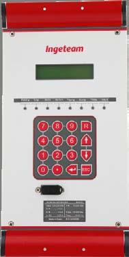
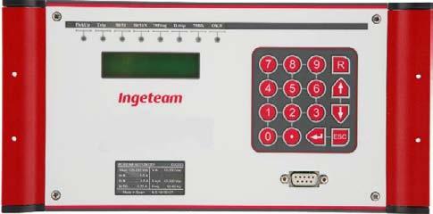
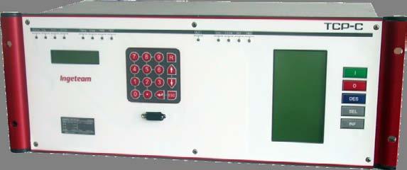
15 KEYPAD/LOCAL DISPLAY 7 RED LEDS AND 1 GREEN/RED LCD 2 LINES WITH 16 CHARACTERS 16-KEY KEYBOARD RS232C connector TESTS DSE_PD300_eng 15
16 TECHNICAL SPECIFICATIONS Auxiliary power supply Vdc Range Vdc Ripple 20 % over the rated value Burden 8W min/ 18W max Vdc Range Vdc Ripple 20% over the rated value Burden 8W min/ 18W max Current circuits Thermal capacity for phase/neutral I Continuous 20 A Short term (1 s.) 500 A Very short term (½ cycles) 1250 A Burden at I = 5 A <0.2 VA Burden at In= 1A <0.02 VA Voltage circuits (PD300-2) Thermal capacity Permanent 260 V Burden at 63.5 V VA Burden at 100 V 0.03 VA Closed terminals for voltage and current inputs (optional) Terminal pitch 9.5 mm Digital inputs and outputs without extension board Number of inputs 8 Number of outputs 7 Digital inputs and outputs with extension board 1 Number of digital inputs 17 Number of digital outputs 14 Optoisolated digital inputs Range Vdc Inactive below 13 Vdc Range Vdc Inactive below 60 Vdc Burden < 3mA Output contacts Trip relays 1 to 6 (and 8 to 13) Carry (permanent) 5 A at 25 ºC Make and carry for 0.5 s 30 A Breaking capacity (L/R=40 ms) Vdc 0.2 A Vdc 0.5 A - 48 Vdc 0.5 A Breaking capacity (resistive) Vdc 0.4 A Vdc 1 A - 48 Vdc 3 A Performance time 8 ms. DSE_PD300_eng 16
17 Auxiliary relay 7 (and 14) Carry (permanent) 5 A at 25 ºC Make and carry for 0.5 s 30 A Breaking capacity (L/R=40 ms) Vdc 0.15 A Vdc 0.3 A - 48 Vdc 0.5 A Breaking capacity (resistive) Vdc 0.2 A Vdc 0.4 A - 48 Vdc 0.2 A Performance time 8 ms. Frequency Programmable system frequency 50 or 60 Hz Operational range Fn ± 5 Hz Communications ports Front communication port RS232C connector DTE 9 pin D type female Cable length 3 m maximum Baud rate bps Insulation No Types of rear communication ports (COM-1 and COM-2) RS232 - RS232C connector DTE 9 pin D type female - Cable type Shielded - Cable length 15 m max. - Insulation 500V RS485 - RS485 connector DTE 9 pin D type female - Cable type Shielded twisted pair - Cable length 1,000 m max. - Insulation 500V G.F.O. - Connector ST - Wavelength 820nm - Attenuation 8 db with 62.5 /125 µm glass fibre - Glass fibre optic Multimode 62.5 /125 µm - Maximum distance 1.5 Km P.F.O. - Connector HP standard - Wavelength 660 nm - Attenuation 24.7 db with 1mm plastic cable 22 db with 200 µm silica cable - Maximum distance 115 m with 1mm plastic cable 1.9 Km with 200 µm silica cable Ethernet RJ45 Connector RJ45 Female Cable type Shielded Cable length 100 m max. Insulation 500V Baud rate 10/100 Mbps G.F.O. Ethernet Connector ST Wavelength 1300nm Permitted attenuation 8 db with 62.5 /125 µm glass fibre Multimode glass optical fibre 62.5 /125 µm Maximum distance 1.5 Km DSE_PD300_eng 17
18 IRIG-B port Input Demodulated Input level TTL Cable type 2-wire, shielded Insulation 500 V Maximum distance 1.5 Km Accuracy Accuracy Class 0.5 for V, I and P (up to 120% nominal) Accuracy in the protected range 3% Curve operation accuracy ±5% or 30ms (the highest of the two values) Battery voltage monitoring (optional) Vdc Range 18 to 60 Vdc Vdc Range 86 to 280 Vdc Mechanical characteristics Weight 2.8 Kg Approx. weight with packaging and documentation 3.8 Kg Front IP IP40 Optional front IP IP54 ENVIRONMENTAL CONDITIONS Operating temperature -20ºC to 75ºC Storage temperature -40ºC to 85ºC Relative humidity Up to 95% without condensation CONSTRUCTION FEATURES PD300-H model dimensions DSE_PD300_eng 18
19 PD300-V model dimensions IEC61850 and TCP model dimensions DSE_PD300_eng 19
20 CONNECTION DIAGRAMS 2 winding, pin terminal models DSE_PD300_eng 20
21 2 windings, closed-terminal models DSE_PD300_eng 21
22 3 windings, pin-terminal models DSE_PD300_eng 22
23 3 windings, closed-terminal models DSE_PD300_eng 23
24 Generator, pin-terminal models DSE_PD300_eng 24
25 Generator, closed-terminal models DSE_PD300_eng 25
26 TRANSFORMER, Parque GENERATOR Tecnológico AND de MOTOR Bizkaia PROTECTION Edificio Zamudio, Bizkaia, Spain Tel Fax Ingeteam Transmission & Distribution, S.A. DSE_PD300_eng 26
The units are available in the following mechanical constructions:
 INTRODUCTION PL-300 units are digital based multifunction protection relays that incorporate simultaneously in a single unit a great number of protection functions that can be selected within a set of
RETROFITTING. Motor Protection Relay. Two mountings are available, Flush Rear Connection (EDPAR) or Projecting Rear Connection (SDPAR).
 or Projecting Rear Connection (SDPAR).") RETROFITTING Motor Protection Relay NPM800R (R2 case) and NPM800RE (R3 case) are dedicated to the refurbishment of 7000 series (R2 and R3 cases) of CEE relays providing the protection of medium voltage
RETROFITTING Motor Protection Relay NPM800R (R2 case) and NPM800RE (R3 case) are dedicated to the refurbishment of 7000 series (R2 and R3 cases) of CEE relays providing the protection of medium voltage
www. ElectricalPartManuals. com Transformer Differential Relay MD32T Transformer Differential Relay
 Transformer Differential Relay The MD3T Transformer Differential Relay is a member of Cooper Power Systems Edison line of microprocessor based protective relays. The MD3T relay offers the following functions:
NTG MULTIFUNCTON GENERATOR PROTECTION RELAY. NTG-Slide
 NTG MULTIFUNCTON GENERATOR PROTECTION RELAY 1 NTG Digital protection relay that integrates a number of functions required r for the protection of generators. It is used in power stations from gas, steam,
Stabilized Differential Relay SPAD 346. Product Guide
 Issued: July 1998 Status: Updated Version: D/21.03.2006 Data subject to change without notice Features Integrated three-phase differential relay, three-phase overcurrent relay and multiconfigurable earth-fault
Generator Protection GENERATOR CONTROL AND PROTECTION
 Generator Protection Generator Protection Introduction Device Numbers Symmetrical Components Fault Current Behavior Generator Grounding Stator Phase Fault (87G) Field Ground Fault (64F) Stator Ground Fault
SPAD 346 C Stabilized differential relay
 SPAD 346 C Stabilized differential relay Stabilized Differential Relay Type SPAD 346 C Features Integrated three-phase differential relay, three-phase overcurrent relay and multiconfigurable earth-fault
Transformer Protection
 Transformer Protection Transformer Protection Outline Fuses Protection Example Overcurrent Protection Differential Relaying Current Matching Phase Shift Compensation Tap Changing Under Load Magnetizing
1 INTRODUCTION ORDER CODE / INFORMATION
 INTRODUCTION ORDER CODE / INFORMATION 269/269Plus * * * * * * 269/269Plus SV D/O.4 ORDER CODE / INFORMATION Motor management relay Standard version Drawout version Phase CT Ground CT (required for D/O
Detecting and Managing Geomagnetically Induced Currents With Relays
 Detecting and Managing Geomagnetically Induced Currents With Relays Copyright SEL 2013 Transformer Relay Connections Voltage Current Control RTDs Transformer Protective Relay Measures differential current
Replacement solution
 Replacement solution for the ABB DPU2000R protection and control relay Specification File, Revision, Date (Pages) Replacement Relay Specification_ABB DPU2000R_0.doc, Revision 0, August 2, 2013 (37) Table
ATV12H037F1 variable speed drive ATV kW hp V - 1ph - with heat sink
 Characteristics variable speed drive ATV12-0.37kW - 0.55hp - 100..120V - 1ph - with heat sink Main Range of product Altivar 12 Product or component type Product destination Product specific application
ATV12H018F1 variable speed drive ATV kW hp V - 1ph
 Characteristics variable speed drive ATV12-0.18kW - 0.25hp - 100..120V - 1ph Main Range of product Altivar 12 Product or component type Product destination Product specific application Assembly style Component
4Q POWER AMPLIFIERS AC AND DC 3000VA 3x3000VA
 PERFORMANCES High accuracy High stability Fast transients High inrush current facilities Wide bandwidth 25 khz at -3dB Internal waveform DC and up to 10 khz Very low distortion Quadrant change without
ATV12HU40M3 variable speed drive ATV12-4kW - 5hp V - 3ph - with heat sink
 Characteristics variable speed drive ATV12-4kW - 5hp - 200..240V - 3ph - with heat sink Main Range of product Altivar 12 Product or component type Product destination Product specific application Assembly
ATV12HU22M2. Main. Range of product Altivar 12. Component name Quantity per set Set of 1. Built-in fan. Motor power hp Communication port protocol
 Product datasheet Characteristics ATV12HU22M2 Complementary Main Range of product Altivar 12 Product or component type Product destination Product specific application Assembly style Component name Variable
Transformer differential protection
 Transformer differential protection Page 1 Issued June 1999 Changed since July 1998 Data subject to change without notice (SE970883) Features Three phase differential protection with two, three, five or
T/3000 T/3000. Substation Maintenance and Commissioning Test Equipment
 T/3000 Substation Maintenance and Commissioning Test Equipment MULTI FUNCTION SYSTEM FOR TESTING SUBSTATION EQUIPMENT SUCH AS: CURRENT, VOLTAGE AND POWER TRANSFORMERS, ALL TYPE OF PROTECTION RELAYS, ENERGY
POWER AMPLIFIERS 4 QUADRANTS 3x500 VA to 3x1500 VA - THREE-PHASES
 PERFORMANCES High accuracy High stability Fast transients High inrush current facilities Wide bandwidth Very low distortion Quadrant change without transition Very low output impedance Low noise RS232
Substation applications
 Substation applications To make it easy to choose the right for a protection application, the most typical applications are presented with the type of for them. Each sample application is presented by:
1 INTRODUCTION 1.1 PRODUCT DESCRIPTION
 GEK-00682D INTRODUCTION INTRODUCTION. PRODUCT DESCRIPTION The MDP Digital Time Overcurrent Relay is a digital, microprocessor based, nondirectional overcurrent relay that protects against phase-to-phase
Generator Protection M 3420
 PROTECTION Generator Protection M 3420 Integrated Protection System for Generators of All Sizes Unit shown with optional M 3920 Target Module and M 3931 HMI (Human-Machine Interface) Module Microprocessor-based
T 1000 PLUS. Secondary Injection Relay Test Set. Designed for testing relays and transducers
 Secondary Injection Relay Test Set Designed for testing relays and transducers Microprocessor controlled With phase angle shifter Frequency generator Test results and settings are saved into local memory
Transformer protection IED RET 670
 Gunnar Stranne Transformer protection IED RET 670 Santiago Septiembre 5, 2006 1 Transformer protection IED RET670 2 Introduction features and applications Differential protection functions Restricted Earth
www. ElectricalPartManuals. com Generator Differential Relay MD32G Rotating Machine Differential Relay
 Generator Differential Relay The MD3G Rotating Machine Differential Relay is a member of Cooper Power Systems Edison line of microprocessor based protective relays. The MD3G relay offers the following
TD 1000 PLUS. Secondary Injection Relay Test Set. Designed for testing relays and transducers
 Secondary Injection Relay Test Set Designed for testing relays and transducers Two current outputs to test differential relays Convertible current and voltage generator With phase angle shifter Frequency
COPYRIGHTED MATERIAL. Index
 Index Note: Bold italic type refers to entries in the Table of Contents, refers to a Standard Title and Reference number and # refers to a specific standard within the buff book 91, 40, 48* 100, 8, 22*,
Multimeter 500CVD21 RTU500 series
 Remote Terminal Units - Data sheet Multimeter 500CVD21 RTU500 series CT/VT interface with 4 voltage and 24 current inputs for direct monitoring of 3/4 wire 0 300 V AC (line to earth), 0...500 V AC (phase
SPECIFICATION FOR OVERCURRENT RELAYS
 SPECIFICATION FOR OVERCURRENT RELAYS 1/9 1. Procedure A manufacturer willing to classify an overcurrent relay according to this specification should provide: A complete file providing a clear, unambiguous
N. TEST TEST DESCRIPTION
 Multi function system for testing substation equipment such as: current, voltage and power transformers, all type of protection relays, energy meters and transducers Primary injection testing capabilities
Protective Relays Digitrip 3000
 New Information Technical Data Effective: May 1999 Page 1 Applications Provides reliable 3-phase and ground overcurrent protection for all voltage levels. Primary feeder circuit protection Primary transformer
Maintenance/Connection/Installation Service life C/O cyclesx1000
 EasyPact MVS 2016 CPB100000 CPB100014 Circuit breaker. Switch disconnector. Common characteristics Number of poles Rated insulation voltage (V) Impulse withstand voltage (kv) Rated operational voltage
Modern transformer relays include a comprehensive set of protective elements to protect transformers from faults and abnormal operating conditions
 1 Transmission transformers are important links in the bulk power system. They allow transfer of power from generation centers, up to the high-voltage grid, and to bulk electric substations for distribution
Instruction Book. M 3425A Generator Protection
 Instruction Book M 3425A Generator Protection TRADEMARKS All brand or product names referenced in this document may be trademarks or registered trademarks of their respective holders. The content of this
DPX³ 250 Electronic 4P - ModbusTable LGR EN v1.01.xls
 GENERAL MODBUS TABLE ORGANIZATION Starting of the Group s Starting of the Group s System Version (Release) System Version (Build) Group Name (Text) Group Code Group Complexity Group Version 1638 000 01
Instruction Book. M-3425A Generator Protection
 Instruction Book M-3425A Generator Protection PROTECTION Generator Protection M 3425A Integrated Protection System for Generators of All Sizes Unit shown with optional M 3925A Target Module and M 3931
ASHIDA Numerical 3OC + 1EF Protection Relay
 PROTH. ERR L5 PKP FAULT DT REC LOCK BF L6 L7 CLOSE TRIP ADR 241B Protection Features : 4 Element (3 Phase + EF + Sensitive EF) Over current IDMT/DMT with instant trip. Programmable (Non- Volatile) Setting
Fault indicator. Application. SPEF 3A2 C 1MRS MBG Issued: April 1999 Status: Updated Version: B/ Data subject to change without notice
 Issued: April 1999 Status: Updated Version: B/08.11.200 Data subject to change without notice Features Versatile, multifunction line fault indicator for distribution networks Overcurrent, earth-fault and
Technical catalogue. Emax Low voltage air circuit-breakers. Hotline:
 Technical catalogue Emax Low voltage air circuit-breakers www.alobitanbd.com Hotline: 01711548558 PAGE : 02 The new Emax have received innumerable international certifications and approval by the major
ATV12H037F1 variable speed drive ATV kW hp V - 1ph - with heat sink
 Characteristics variable speed drive ATV12-0.37kW - 0.55hp - 100..120V - 1ph - with heat sink Product availability : Stock - Normally stocked in distribution facility Price* : 191.76 USD Main Range of
NO WARRANTIES OF ANY KIND ARE IMPLIED ON THE INFORMATION CONTAINED IN THIS DOCUMENT.
 MODBUS/BECO2200-M3425A Communication Data Base for M-3425A Integrated Protection System Device I.D. = 150 Specifications presented herein are thought to be accurate at the time of publication but are subject
SWT 3000 Teleprotection technical data siemens.com
 Power network telecommunication SWT 3000 Teleprotection technical data siemens.com Sustainable success for high-voltage power networks The SWT 3000 Teleprotection system has been the first choice for reliable
High-set undervoltage stage with definitetime. or inverse definite minimum time (IDMT) characteristic. Low-set undervoltage stage with definitetime
 characteristic. Low-set undervoltage stage with definitetime") Issued: 5.06.999 Status: 5.06.999 Version: B/09..00 Data subject to change without notice Features Overvoltage and undervoltage protection Single- or three-phase operation High-set overvoltage stage with
Issued: 5.06.999 Status: 5.06.999 Version: B/09..00 Data subject to change without notice Features Overvoltage and undervoltage protection Single- or three-phase operation High-set overvoltage stage with
[ tima-datasheet-en v11.1 ]
![[ tima-datasheet-en v11.1 ]](/thumbs/92/109134204.jpg "[ tima-datasheet-en v11.1 ]") specifically designed for protection, automation and control applications in power systems 60 ns (99%) maximum time deviation single or dual 10/100Base-T Ethernet port(s) VLAN / IEEE 802.1Q support RS232
specifically designed for protection, automation and control applications in power systems 60 ns (99%) maximum time deviation single or dual 10/100Base-T Ethernet port(s) VLAN / IEEE 802.1Q support RS232
e 2 TANGO-50 Short-Circuit Detector K Data Sheet
 e 2 TANGO-50 Short-Circuit Detector K-31.2.1 Data Sheet We Create Ideas With Power! e 2 TANGO-50 short-circuit detector is a product of ELEKTROMETAL ENERGETYKA SA developed by our engineers with extensive
Multifunction network analyzer Q15U Q96U2L - Q96U4... Q15E Q96E MCU - MCUH Programmable transducer MCUU
 Multifunction network analyzer Q15U2... - Q96U2L - Q96U4... Q15E2... - Q96E2... - MCU - MCUH Programmable transducer MCUU OPERATING MANUAL Ipm0163.8 - Edition 06.09 Langer Messtechnik GmbH Soyerhofstrasse
A proven distribution feeder solution with integrated protection, monitoring, and control
 SEL-35 Protection System A proven distribution feeder solution with integrated protection, monitoring, and control Achieve sensitive and secure fault detection using comprehensive protection functions.
sw rev. 55B DEVICE FOR THE PERMANENT CONTROL OF INSULATION ON THE SUPPLY LINES IN MEDICAL PRACTICE PLACES INSTALLATIONS
 INSTRUCTIONS MANUAL IM831-U v0.92 HRI-R40W sw rev. 55B DEVICE FOR THE PERMANENT CONTROL OF INSULATION ON THE SUPPLY LINES IN MEDICAL PRACTICE PLACES INSTALLATIONS INDEX: GENERAL TYPES ACESSORIES AND OPTIONS
Generator Protection M 3425A
 PROTECTION Generator Protection M 3425A Integrated Protection System for Generators of All Sizes Unit shown with optional M 3925A Target Module and M 3931 HMI (Human Machine Interface) Module Exceeds IEEE
Protection and control. Sepam range Sepam 2000 Metering and protection functions
 Protection and control Sepam range Sepam 2 Metering and protection functions Contents chapter / page metering functions 1/1 protection functions 2/1 appendix 3/1 Notation c Sepam 2 may include several
SEL-787-3, -4 Transformer Protection Relay
 SEL-787-3, -4 Transformer Protection Relay SEL-787-3E Model SEL-787-3S Model SEL-787-4X Model Major Features and Benefits The SEL-787 Transformer Protection Relay provides unsurpassed protection, integration,
Transformer Protection Principles
 Transformer Protection Principles 1. Introduction Transformers are a critical and expensive component of the power system. Due to the long lead time for repair of and replacement of transformers, a major
Power Processor - Series 700F 10KVA to 150KVA
 Power Processor - Series 700F 10KVA to 150KVA Power Conditioning and Regulation for Commercial & Industrial Equipment General Specifications PART 1 - GENERAL 1.1 DESCRIPTION This specification defines
APPLICATION: The heart of the system is a DSR 100 Digital Static Regulator used in conjunction with standard SCR based rectifier bridges.
 APPLICATION: Basler Electric offers a New Line of digitally controlled brush (static) or brushless excitation systems designed for use with existing Hydro, Gas as well as Diesel driven generators requiring
Request Ensure that this Instruction Manual is delivered to the end users and the maintenance manager.
 Request Ensure that this Instruction Manual is delivered to the end users and the maintenance manager. 1 -C - Safety section - This Safety section should be read before starting any work on the relay.
CROSS Chassis from 160 A to 450 A
 CROSS Chassis from 160 A to 450 A STS CATALOGUE Important note! The technical data enclosed is for general information. Please note that the operating instructions and references indicated on the products
Overcurrent Elements
 Exercise Objectives Hands-On Relay Testing Session Overcurrent Elements After completing this exercise, you should be able to do the following: Identify overcurrent element settings. Determine effective
FMR. Ultra Line FEEDER MANAGER RELAY
 Ultra Line FEEDER MANAGER RELAY Protective Functions F49 : One Thermal Image element F50/51/67 : Three levels for phase overcurrent independentely programmable as directional or non directional F50N/51N/67N
System Protection and Control Subcommittee
 Power Plant and Transmission System Protection Coordination Volts Per Hertz (24), Undervoltage (27), Overvoltage (59), and Under/Overfrequency (81) Protection System Protection and Control Subcommittee
DPF-MAC Auto power factor controller
 Digital Electric& Electronics System DPF-MAC Auto power factor controller MULTI POWER FACTOR AUTOMATIC MULTI POWER FACTOR AUTOMATIC Introduction DPF-MAC increases usage efficiency by controlling the power
ADJUSTABLE SPEED DRIVES. W7 Series. 18 Pulse
 ADJUSTABLE SPEED DRIVES W7 Series 18 Pulse Meets or Exceeds Your Specifications Standard Specifications Item Voltage Class 460V Maximum HP 60 75 100 125 150 200 250 300 400 500 600 700 800 Drive Rating
INSTRUCTION MANUAL TRANSFORMER PROTECTION RELAY GRT100 - B
 INSTRUCTION MANUAL TRANSFORMER PROTECTION RELAY GRT00 - B Toshiba Energy Systems & Solutions Corporation 207 All Rights Reserved. ( Ver. 3.) Safety Precautions Before using this product, be sure to read
200ADM-P. Current Injection System with Phase Shift A 3.000s 2.000A 50.00Hz 0.0. Features
 CT ratio Power Harmonics ac+dc 200ADM-P Current Injection System with Phase Shift Features 0-200A output current True RMS metering with 1 cycle capture Variable auxiliary AC voltage/current output with
PROTECTION of electricity distribution networks
 PROTECTION of electricity distribution networks Juan M. Gers and Edward J. Holmes The Institution of Electrical Engineers Contents Preface and acknowledgments x 1 Introduction 1 1.1 Basic principles of
Modular range of digital protection relays
 S e p a m s e r i e s 2 0, 4 0, 8 0 Modular range of digital protection relays Fast Dependable Simple Fast response Maximum dependability Your electrical equipment is under control. With Sepam protection
ASHIDA Numerical Directional 3OC + 1EF Protection Relay
 Ashida Numerical Directional 3O/C + 1E/F PROTH. PROTH. ERR L5 FAULT PKP PKP FAULT L6 PT DT REC LOCK BF L7 CLOSE TRIP TRIP CLOSE ADR 145B 245B Protection Features: 4 Element (3 Phase + EF +sensitive EF)
Technical Datasheet. True RMS Digital Protection Relay. Line Monitoring Relay
 Technical Datasheet RELAY-1 RELAY-2 k V Hz RESET ABH TEST True RMS Measurement True RMS Digital Protection V/Hz is used to protect against Over Voltage, Under Voltage, Phase Unbalance, Phase Sequence detection,
RISH PQM. Power Quality Monitor. Preliminary Datasheet subject to change without notice. Individual Harmonics measurement upto 56th Harmonics
 Power Quality Monitor Individual Harmonics measurement upto 56th Harmonics True representation of Voltage & Current waveforms. Phasor Representation of All 3 phases for system analysis Real Time Clock
g GE POWER MANAGEMENT
 469 FREQUENTLY ASKED QUESTIONS 1 Can not communicate through the front port RS232 Check the following settings Communication port on your computer ( com1, com2 com3 etc ) Parity settings must match between
Generator Protection M 3425
 PROTECTION Generator Protection M 3425 Integrated Protection System for Generators of All Sizes Unit shown with optional M 3925 Target Module and M 3931 HMI (Human Machine Interface) Module Provides all
Improving Transformer Protection
 Omaha, NB October 12, 2017 Improving Transformer Protection Wayne Hartmann VP, Customer Excellence Senior Member, IEEE Wayne Hartmann Senior VP, Customer Excellence Speaker Bio whartmann@beckwithelectric.com
Data Sheet. RISH Master Record %THD
 Data Sheet %THD Application : measures important electrical parameters & replaces the multiple analog panel meters. It measures electrical parameters like AC current, Voltage, frequency, active energy
INSTRUCTIONS MANUAL DEVICE FOR THE PERMANENT CONTROL OF INSULATION ON THE SUPPLY LINES IN MEDICAL PRACTICE PLACES INSTALLATIONS HRI-R40W
 Page 2 / 16 INDEX: GENERAL TYPES ACESSORIES AND OPTIONS INSTALLATION WIRING DIAGRAMS CONNECTING TERMINALS DIAGRAMS WIRING DIAGRAM DESCRIPTION WORKING DESCRIPTION AND KEYBOARD WORKING DESCRIPTION AND PROGRAMMING
Advanced Test Equipment Rentals ATEC (2832)
") Established 1981 Advanced Test Equipment Rentals www.atecorp.com 800-404-ATEC (2832) The toolbox for substation 3-phase testing Three currents and four voltages Stand-alone functionality Rugged and reliable
Established 1981 Advanced Test Equipment Rentals www.atecorp.com 800-404-ATEC (2832) The toolbox for substation 3-phase testing Three currents and four voltages Stand-alone functionality Rugged and reliable
Utility Communications Teleprotection Equipment TPT-200
 Utility Communications Teleprotection Equipment TPT-200 5C Communications Inc. All rights reserved Teleprotection is designed to transfer protection commands coming, in most cases, from distance protection
AV-300i Specifications. Saftronics Inc. PC10 Product Specifications PC10. Mini Vector AC Drive
 Saftronics Inc. www.saftronics.com TM AV-300i Specifications PC10 Product Specifications PC10 Mini Vector AC Drive 1 (1) T hree-phas e 230V input Drive Hp 1/8 1/4 1/2 1 2 3 5 7.5 10 Nominal applicable
IRIG-B Interface (De-modulated) External clock synchronization signal IRIG format B00X
 External clock synchronization signal IRIG format B00X") P847B&C Technical Data Sheet INTERFACES IRIG-B (De-modulated) Use Standard Connector Cable type Isolation Input signal Input impedance at dc Accuracy IRIG-B Interface (De-modulated) External clock synchronization
P847B&C Technical Data Sheet INTERFACES IRIG-B (De-modulated) Use Standard Connector Cable type Isolation Input signal Input impedance at dc Accuracy IRIG-B Interface (De-modulated) External clock synchronization
N. TEST TEST DESCRIPTION
 Multi function system for testing substation equipment such as: current, voltage and power transformers, over-current protection relays, energy meters and transducers Primary injection testing capabilities
1 st Edition INTRODUCTION
 INTRODUCTION The RCU 220, part of Efacec CLP-500 platform, is a recloser and sectionalizer controller that provides a cost-effective and secure solution for feeder protection and automation. Drawing on
Temperature Controller model MFC-301/T-Dry. Version for Dry Transformers and Motors. Technical Manual. Licht
 Temperature Controller model MFC-301/T-Dry Version for Dry Transformers and Motors Technical Manual Licht Contents 1 Introduction 2 2 Operating principle 3 2.1 General principle 3 2.2 RTD operation 3 3
Protection Relays. U-MLEs-PLv. Ultra Line. DC SUBSTATION PROTECTIVE RELAY (double voltage Line Test) 32, 45, 49, 64, 76, 79, 80
 32, 45, 49, 64, 76, 79, 80") Ultra Line DC SUBSTATION PROTECTIVE RELAY (double voltage Line Test) 3, 45, 49, 64, 76, 79, 80 D.C. Feeder protection relay with setting parameters programmable locally or via serial communication. Suitable
Ultra Line DC SUBSTATION PROTECTIVE RELAY (double voltage Line Test) 3, 45, 49, 64, 76, 79, 80 D.C. Feeder protection relay with setting parameters programmable locally or via serial communication. Suitable
Phase and neutral overcurrent protection
 Phase and neutral overcurrent protection Page 1 ssued June 1999 Changed since July 1998 Data subject to change without notice (SE970165) Features Two-phase or three-phase time-overcurrent and earth fault
RS232 AC-DC VOLTAGE POWER AMPLIFIERS PCU-10K / 15K / 20K / 24K-AB/4G/HP PERFORMANCES APPLICATIONS DESCRIPTION COMMERCIAL REFERENCES
 PERFORMANCES High accuracy High stability Fast transients High inrush current facilities Wide bandwidth Very low distortion Quadrant change without transition Very low output impedance RS232 APPLICATIONS
DECS-200N-C1 Negative Forcing Digital Excitation Control System
 DECS-200N-C1 Negative Forcing Digital Excitation Control System The DECS-200N is a very compact Negative Forcing Digital Excitation Control System. This compact design accommodates 63 Vdc and 125 Vdc applications
System Protection and Control Subcommittee
 Power Plant and Transmission System Protection Coordination Reverse Power (32), Negative Sequence Current (46), Inadvertent Energizing (50/27), Stator Ground Fault (59GN/27TH), Generator Differential (87G),
Power factor correction and harmonic filtering. Automatic power factor regulators
 Power factor correction and harmonic filtering Automatic power factor regulators Automatic power factor reguladors R.1 - Automatic power factor regulators Selection table R1-4 computer Plus-T Intelligent
ADJUSTABLE SPEED DRIVES. HX7 Series. 18 Pulse. Phone: Fax: Web: -
 ADJUSTABLE SPEED DRIVES HX7 Series 18 Pulse Toshiba HX7 In some industrial applications, users need reliable and efficient adjustable speed drives that do not contribute significant harmonic distortion
Protection of Electrical Networks. Christophe Prévé
 Protection of Electrical Networks Christophe Prévé This Page Intentionally Left Blank Protection of Electrical Networks This Page Intentionally Left Blank Protection of Electrical Networks Christophe Prévé
Relay. Technical Datasheet. True RMS Digital Protection Relay. Line Monitoring Relay
 Line Monitoring Technical Datasheet RISH RELAY-1 RELAY-2 RISHABH k V Hz True RMS Digital Protection RISH V/Hz is used to protect against Over Voltage, Under Voltage, Phase Unbalance, Phase Sequence detection,
Digital Motor Bus Transfer System M 4272
 SYNCHRONIZING Digital Motor Bus Transfer System M 4272 Integrated Synchronizing System Provides Automatic and Manual transfers of motor bus systems in power plants and industrial processing plants to ensure
System configuration. Ratings 400 V Class three-phase 90 to 800 kw 690 V Class three-phase 90 to 1000 kw SX-D. Frequency inverters.
 ~ ~ SX High performance Vector Control IP54 full range. Compact design & Robustness Built-in Filter according to C3 Class Built-in Fusses (From 200 kw) Safety according EN13849-1 and EN62061 standards
RI-F200 Series. Single and Three Phase Multifunction Energy Meter. Telephone : +44 (0) Displayed Parameters
 Displayed Parameters") RI-F200 Series Single and Three Phase Multifunction Energy Meter DIN 96 panel mounted -/1A or -/5A current transformer input Single phase or three phase network compatible Programmable voltage and current
RI-F200 Series Single and Three Phase Multifunction Energy Meter DIN 96 panel mounted -/1A or -/5A current transformer input Single phase or three phase network compatible Programmable voltage and current
489 Generator Management Relay Instruction Manual
 Digital Energy Multilin Firmware Revision: 4.0X Manual Part Number: 1601-0150-AF Manual Order Code: GEK-106494P Copyright 2011 GE Multilin 489 Generator Management Relay Instruction Manual GE Multilin
SIPROTEC Compact 7SJ80 V4.6 Overcurrent Time Protection
 SIPROTEC Compact 7SJ80 V4.6 Overcurrent Time Protection Technical Data Extract from manual E50417-G1140-C343-A4, chapter 4 Energy Automation Note For safety purposes, please note instructions and warnings
SEL-311C TRANSMISSION PROTECTION SYSTEM
 SEL-3C TRANSMISSION PROTECTION SYSTEM ADVANCED TRANSMISSION LINE PROTECTION, AUTOMATION, AND CONTROL Bus ANSI NUMBERS/ACRONYMS AND FUNCTIONS 52 3 3 2 P G 8 O U 27 68 50BF 67 P G Q 50 P G Q 59 P G Q 5 P
S E R I E S PROTECTION RELAY USER MANUAL V 1.8.2
 4000 S E R I E S PROTECTION RELAY USER MANUAL V 1.8.2 I. TABLE OF CONTENTS 1 Introduction... 16 2 Operating environment... 18 Transformer protection... 19 Communication network... 22 ALP-4000 series function
DRTS-6. DRTS-6 has been designed to test: DRTS-6. Advanced Protection Relay Test Set and Measurement System
 DRTS-6 Advanced Protection Relay Test Set and Measurement System MULTI-TASKING EQUIPMENT DESIGNED FOR TESTING PROTECTION RELAYS, ENERGY METERS, TRANSDUCERS POWERFUL AND LIGHTWEIGHT HIGH ACCURACY: BETTER
Instantaneous Overcurrent Relay
 Midos Type MCRI Instantaneous Overcurrent Relay Features High speed operation Not slowed by dc transients Settings readily adjustable on relay front plate Two phase and earth fault relay Figure 1: Type
Capacitor protection relay
 Capacitor Protection Relay FEATURES Capacitor unbalance protection Line current unbalance protection Overvoltage protection Overheating protection Ground fault protection Overcurrent protection Undercurrent
PS-3000-AVAS PS-5000-AVAS DC SOURCE FOR AUTOMOTIVE TESTS
 PERFORMANCES High accuracy High stability Fast times of transition High inrush current Wide bandwidth Switching from Q1 to Q4 without transition Very low output impedance Ripple & noise superposition Dips