Maintenance/Connection/Installation Service life C/O cyclesx1000
|
|
|
- Rodger Holland
- 5 years ago
- Views:
Transcription

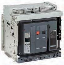
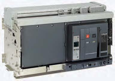
1 EasyPact MVS 2016
 Impulse withstand voltage (kv) Rated operational voltage (V AC 50/60 Hz) 3/4 Ui 1000 Uimp 12 Ue 690 Suitability for isolation IEC")
2 CPB CPB Circuit breaker. Switch disconnector. Common characteristics Number of poles Rated insulation voltage (V) Impulse withstand voltage (kv) Rated operational voltage (V AC 50/60 Hz) 3/4 Ui 1000 Uimp 12 Ue 690 Suitability for isolation IEC Yes Degree of pollution IEC Basic circuit-breaker Circuit-breaker as per IEC Rated current (A) Rating of 4th pole (A) Sensor ratings (A) Type of circuit breaker Ultimate breaking capacity (ka rms) V AC 50/60 Hz Rated service breaking capacity (ka rms) Utilisation category Rated short-time withstand current (ka rms) V AC 50/60 Hz Rated making capacity (ka peak) V AC 50/60 Hz Breaking time (ms) between tripping order and arc extinction Closing time (ms) In at 40 C (1) Icu (2) Ics (2) V 690 V % Icu Icw (2) 1s V 690V 3s 440/690V Icm (2) Switch-disconnector as per IEC and Annex A Type of switch-disconnector Operational current AC23A Rated making capacity (ka peak) Rated short-time withstand current (ka rms) Maintenance/Connection/Installation Service life C/O cyclesx1000 Connection Icm Icw 1s 3s V 690 V Mechanical with maintenance without maintenance Electrical without maintenance 440 V 690 V Horizontal Vertical Dimensions (mm) Draw-out 3P (H x W x D) 4P Fixed 3P 4P Weight (kg) Draw-out 3P/4P (approximate) Fixed 3P/4P (1) Refer page no. B-12 for details on temperature derating. (2)
3 MVS08 MVS10 MVS12 MVS16 MVS20 MVS25 MVS32 MVS N H N H N H N H N H N H N H N H % 100% 100% 100% 100% 100% 100% 100% B B B B B B B B <70 <70 <70 <70 <70 <70 <70 <70 MVS08 MVS10 MVS12 MVS16 MVS20 MVS25 MVS32 MVS40 NA HA NA HA NA HA NA HA NA HA NA HA NA HA NA HA Yes Yes 439 x 441 x x 556 x x 422 x x 537 x /85 90/120 40/50 60/80
4
5
6 Micrologic E control units protect power circuits. They also offer measurements, display, communication and current maximeters. Version 6 provides earth-fault protection. "Ammeter" measurements (Micrologic A) "Energy meter" measurements (Micrologic E) True RMS current (I1, I2, I3, In, Ig): Micrologic A / Micrologic E current demand voltages: phase to phase, phase to neutral, average (1) and unbalanced (1) E instantaneous power: P, Q, S power factor: PF power demand: P demand 11 energy: Ep, Eq (1), Es (1). Accuracy of active energy Ep is 2 % (including the sensors). The range of 10 measurement is the same as current with Micrologic A, depending of an external power supply module (24 V DC). Communication option In conjunction with the COM communication option, the control unit transmits the 12 following: settings all "ammeter" and "energy" measurements enable connection to FDM121 (E only) tripping causes maximeter / minimeter readings. Protection Protection thresholds and delays are set using the adjustment dials. Overload protection 13 True rms long-time protection. Thermal memory: thermal image before and after tripping. Setting accuracy may be enhanced by limiting the setting range using a different longtime 14 rating plug. Overload protection can be cancelled using a specific LT rating plug "Off". Short-circuit protection Short-time (rms) and instantaneous protection. Selection of I 2 t type (ON or OFF) for short-time delay. Earth-fault protection 1 Source ground return earth fault protection. 4 2 Selection of I 2 t type (ON or OFF) for delay. Neutral protection 6 On three-pole circuit breakers, neutral protection is not possible. On four-pole circuit breakers, neutral protection may be set using a three-position switch: neutral unprotected (4P 3d), neutral protection at 0.5Ir (4P 3d+ N/2), neutral 5 7 protection at Ir (4P 4d). Zone selective interlocking (ZSI) 9 A ZSI terminal block may be used to interconnect a number of control units to provide total discrimination for short-time and earth-fault protection, without a delay before 8 3 tripping. Overload alarm A yellow alarm LED goes on when the current exceeds the long-time trip threshold. M2C programmable contacts The M2C (two contacts) programmable contacts may be used to signal envents (Ir, Isd, Alarm Ir, Alarm Ig, Ig). They can be programmed using the keypad on the Micrologic E control unit or remotely using the COM option (BCM ULP). 1 overload alarm (LED) at Ir Fault indications 2 long-time rating plug screw LEDs indicate the type of fault: test connector overload (long-time protection Ir) long-time threshold and tripping delay short-circuit (short-time Isd or instantaneous li protection) short-time pick-up earth fault (Ig) 6 short-time tripping delay internal fault (Ap). 7 instantaneous pick-up 8 earth-fault pickup and tripping delay Trip history (E only) 9 earth-fault test button The trip history displays the list of the last 10 trips. For each trip, the following 10 indicator of tripping cause indications are recorded and displayed: 11 lamp test, reset and battery test the tripping cause: Ir, Isd, li, Ig or Auto-protection (Ap) trips 12 digital display the date and time of the trip (requires communication option). A E 13 three-phase bargraph and ammeter Battery power 14 navigation button to view menu contents The fault indication LEDs remain on until the test/reset button is pressed. Under 15 navigation button to change menu normal operating conditions, the battery supplying the LEDs has a service life of 16 navigation button "quick View" approximately 10 years. Test A mini test kit or a portable test kit may be connected to the test connector on the front (1) Display on FDM121 only. Note: Micrologic E control units come with a transparent leadseal cover as standard. to check circuit-breaker operation. For Micrologic 6.0 E control units, the operation of earth-fault or earth-leakage protection can be checked by pressing the test button located above the test connector. DB126649
7 Micrologic ETA ammeter Micrologic ETV voltage meter CDB ETV trip units include all the functions offered by ETA. In addition, they measure voltage values. They also offer trip history & display tripping cause. 15 6G only ETV only long time time Ir.7.8 tr.9 (s) alarmm x In at 6Ir Ir short time short time instantaneous instantaneous Isd 3 4 tsd I i 5 (s) oon ṅ 1 I t off ofof ff x Ir x In setting delay test test Ig D E (s) tg F (s) C G.3.2 B H.2.1 A I on.1 on I 2 0off t off ground fault ground fault ETV only 1 Long-time threshold and tripping delay. 2 Overload alarm (LED) at 1,125 Ir. 3 Short-time pick-up and tripping delay. 4 Instantaneous pick-up. 5 Earth-fault pick-up and tripping delay. 6 Earth-fault test button. 7 Long-time rating plug screw. 8 Test connector. 9 Lamp test, reset and battery test. 10 Indication of tripping cause. 11 Digital display. 12 Three-phase bargraph and ammeter. 13 Navigation button quick View (only with ETV). 14 Navigation button to view menu contents. 15 Navigation button to change menu. ETV only (1) The thermal memory continuously accounts for the amount of heat in the cables, both before and after tripping, whatever the value of the current(presence of an overload or not).the thermal memory optimises the long-time protection function of the circuit breaker by taking into account the temperature rise in the cables.the thermal memory assumes a cable cooling time of approximately 20 minutes. (2) Refer to page D-5 for more details on ZSI. Note: ETV trip units come with a transparent leadseal cover as standard Voltage meter measurements In addition to the ammeter measurements of ETA ETV trip units measure and display: Current demand Voltages: phase to phase, phase to neutral, average and unbalanced The range of measurement is the same as current with ETA, depending of an external power supply module. Protection Protection thresholds and delays are set using the adjustment dials. Overload protection True rms long-time protection. Protects cables (phase and neutral) against overloads Thermal memory (1) : thermal image before and after tripping. Short-time protection The short-time protection function protects the distribution system against impedant short-circuits The short-time tripping delay can be used to ensure discrimination with downstream circuit breaker The I 2 t ON and I 2 t OFF options enhance discrimination with a downstream protection devices Use of I 2 t curves with short-time protection: I 2 t OFF selected: the protection function implements a constant time curve I 2 t ON selected: the protection function implements an I 2 t inverse-time curve up to 10 lr. Above 10 lr, the time curve is constant Earth-fault protection on ETV6G trip system Residual or source ground return earth fault protection. Selection of I 2 t type (ON or OFF) for delay. A ground fault in the protection conductors can provoke local temperature rise at the site of the fault or in the conductors. The purpose of the ground-fault protection function is to eliminate this type of fault. Type Residual Description The function determines the zero-phase sequence current, i.e. the vectorial sum of the phase and neutral currents It detects faults downstream of the circuit breaker Instantaneous protection The Instantaneous-protection function protects the distribution system against solid short-circuits. Contrary to the short-time protection function, the tripping delay for instantaneous protection is not adjustable. The tripping order is sent to the circuit 20 milliseconds. Neutral protection On three-pole circuit breakers, neutral protection is not possible. On four-pole circuit breakers, neutral protection may be set using a three-position switch: neutral unprotected (4P 3d), neutral protection at 0.5 Ir (4P 3d + N/2), neutral protection at Ir (4P 4d). Zone selective interlocking (ZSI) A ZSI (2) terminal block may be used to interconnect a number of control units to provide total discrimination for short-time and earth-fault protection, without a delay before tripping. Overload alarm A yellow alarm LED goes on when the current exceeds the long-time trip threshold. Fault indications LEDs indicate the type of fault: Overload (long-time protection Ir) Short-circuit (short-time Isd or instantaneous li protection) Earth fault (Ig) Internal fault (Ap) Trip history The trip history displays the list of the last 10 trips. For each trip, the following indications are recorded and displayed: the tripping cause: Ir, Isd, Ii, Ig or Auto-protection (Ap) trips Battery power The fault indicating LEDs are powered by an in-built battery. The fault indication LEDs remain on until the test/reset button is pressed. Test A hand-held test kit may be connected to the test connector on the front to check circuit-breaker operation. For ETV6G trip unit, the operation of earth-fault protection can be checked by pressing the test button located above the test connector.
8 Protection MVS ETA5S ETA6G ETV5S ETV6G NW 2.0A 5.0A 6.0A 2.0E 5.0E 6.0E Long time (Ir) Current setting (A) trip between 1.05 & 1.20 x Ir Ir = 0.4~1 x In Time setting (s) tr = 0.5~24 Time delay (s) accuracy: 0 to -30%, 1.5 x Ir 12.5~600 accuracy: 0 to -20%, 6 x Ir 0.7~24 accuracy: 0 to -20%, 7.2 x Ir 0.7~16.6 Thermal memory 20 minutes before and after tripping Instantaneous (Isd) Pick-up (A) accuracy: ±10% Isd = 1.5~10 x Ir Time delay (s) max. resettable time: 20ms max. break time: 80ms Short time (Isd) Pick-up (A) accuracy: ±10% Isd = 1.5~10 x Ir Time setting tsd (s) I 2 t Off: 0~0.4 I 2 t On: 0.1~0.4 Time delay (ms) at 10 x Ir max. resettable time tsd: 20~350 (I 2 t off or I 2 t on) max. break time tsd: 80~500 Instantaneous (Ii) Pick-up (A) accuracy: ±10% Ii = 2~15 x In or off Time delay (s) max. resettable time: 20ms max. break time: 50ms Earth fault (Ig) Pick-up (A) Ig = In<400A 0.3~1 x In (accuracy: ±10%) 400A<In<1250A 0.2~1 x In In 1250A 500~1200A Time setting tg (s) I 2 t Off: 0~0.4 I 2 t On: 0.1~0.4 Time delay (ms) max. resettable time tg: 20~350 at In or 1200A (I 2 t off or I 2 t on) max. break time tg: 80~500 Ammeter & Energy type range accuracy Instantaneous current I1, I2, I3, IN 0.2~1.2 x In ±1.5% Ig 0.2~1 x In ±10% 0.05~1 x In ±10% Current maximeters I1, I2, I3, IN 0.2~1.2 x In ±1.5% Demand currents I1, I2, I3, Ig 0.2~1 x In ±1.5% Voltages VL-L & VL-N 100~690V ±0.5% Active power P 30~2000kW ±2% Power factor PF 0~1 ±2% Demand power P demand 30~2000kW ±2% Active energy Ep ~10 10 GWh ±2% Note: all current-based protection functions require no auxiliary source. The test / reset button resets maximeters, clears the tripping indication and tests the battery. MVS ETA5S ETA6G ETV5S ETV6G NW 2.0A 5.0A 6.0A 2.0E 5.0E 6.0E for 5.0P, 6.0P and other Micrologic control units please contact us for more information. As standards, specifications and designs change from time to time, please ask for confirmation of the information given in this publication. Aug.2016
Micrologic control units 2.0 E X Y Z. Overview of functions. Functions and characteristics
 Overview of functions All Masterpact circuit breakers are equipped with a Micrologic control unit that can be changed on site. Control units are designed to protect Power circuits and loads. Alarms may
Introduction Characteristics and performance of Compact NSX circuit breakers from 100 to 250 A up to 690 V
 Functions and characteristics Introduction Characteristics and performance of Compact NSX circuit reakers from to A up to 69 V PB.eps PB6_.eps PB_.eps Compact NSX/6/. Compact NSX R. Compact NSX HB. ()
 SINCE 1989 Quality Products, Prompt Services, Trustful Relationships www.kmindustrialcorp.com KM Industrial Corporation has estalished itself as a trusted supplier of Electrical, Machinery and Industry
Mould circ. Moulded case circuit-breakers
 Mould circ Moulded case circuit-breakers Moulded case circuit-breakers Tmax Contents Power distribution circuit-breakers Technical Data... 7/6 Ordering details Reading information... 7/15 Tmax T1... 7/20
Technical catalogue. Emax Low voltage air circuit-breakers. Hotline:
 Technical catalogue Emax Low voltage air circuit-breakers www.alobitanbd.com Hotline: 01711548558 PAGE : 02 The new Emax have received innumerable international certifications and approval by the major
Micrologic 5 and 6 Electronic Trip Units User Guide
 .9 3.9.9 4 1.9 6 4 3 5.5 6 8 1.5 1 0 Micrologic 5 and 6 Electronic Trip Units User Guide for PowerPact H-, J-, and L-Frame Circuit Breakers Instruction Bulletin 48940-31-01 Rev. 04, 07/015 Retain for future
3 - Protection components Circuit-breakers
 Contents - Protection components Circuit-breakers for the motor protection Selection guide..............................................page /2 Thermal-magnetic motor circuit-breakers Selection guide..............................................page
from 0.5 to 125 A Electrical characteristics Sensitivity type (ma) a AC Electrical auxiliaries Auxiliary and alarm switches (OF-SD)
 a AC Electrical auxiliaries Auxiliary and alarm switches (OF-SD)") Acti 9 Acti 9 circuit reakers from 0.5 to 125 A 056903N-32_SE.eps 056806N-28_SE.eps PB104440_28.eps PB107141_28.eps Acti 9 circuit reaker C120N Numer of poles 1 2-3-4 Electrical characteristics Rated current
Acti 9 Acti 9 circuit reakers from 0.5 to 125 A 056903N-32_SE.eps 056806N-28_SE.eps PB104440_28.eps PB107141_28.eps Acti 9 circuit reaker C120N Numer of poles 1 2-3-4 Electrical characteristics Rated current
A9 R Range Family Code Internal code Poles Code Rating (A) Code Acti 9 (A9) iid R
 Code Acti 9 (A9) iid R") Earth leakage protection Principle of catalogue numers A9 R 15 2 63 Range Family Code Internal code Poles Code Rating (A) Code Acti 9 (A9) iid R 0 0 0 00 Vigi ic60 V 1P 1 0.5 70 ic60 F 2P 2 0.75 71 ik60
Earth leakage protection Principle of catalogue numers A9 R 15 2 63 Range Family Code Internal code Poles Code Rating (A) Code Acti 9 (A9) iid R 0 0 0 00 Vigi ic60 V 1P 1 0.5 70 ic60 F 2P 2 0.75 71 ik60
Merlin Gerin Circuit breaker application guide
 Reset Micrologic 70 Ir Isd Ig Ap reset I i I n 0 1 2 5 3 push OFF push ON O OFF discharged NX 32 H 2 Ue Icu 220/440 525 690 cat.b (V) (ka) Ics = 100% Icu IEC 947-2 EN 60947-2 100 100 85 Icw 85kA/1s 50/60Hz
(With the possibility of a tripping coil for remote control) (Generally optional with an electronic tripping device)
 (Generally optional with an electronic tripping device)") Page 1 of 22 Personal tools Log in / create account Circuit-breaker From Electrical Installation Guide The circuit-breaker/disconnector fulfills all of the basic switchgear functions, while, by means of
Page 1 of 22 Personal tools Log in / create account Circuit-breaker From Electrical Installation Guide The circuit-breaker/disconnector fulfills all of the basic switchgear functions, while, by means of
PD300. Transformer, generator and motor protection Data sheet
 PD300 Transformer, generator and motor protection Data sheet DSE_PD300_eng_AO No part of this publication may be reproduced by whatever means without the prior written permission of Ingeteam T&D. One of
Miniature circuit breakers. Residential current circuit breakers. Busbar systems. Comfort functions/energy control. Residential enclosures
 .2..4.5.6.7 Technical data Series ME07 Standard range S, S, 0/690V/AC High performance range H, 0/690V/AC High performance range H/S, 000V/AC Disconnecting switch MET DC circuit breaker ME 6T up to 0V/DC
Coordination of LV protection devices
 Technical collection Coordination of LV protection devices Low voltage expert guides n 5 DBTP107EN_Couv.indd 1 12/06/2009 14:32:52 Sans titre-1 1 12/06/2009 14:13:13 Contents Glossary 2 The requirements
TeSys circuit-breakers Thermal-magnetic motor circuit-breakers types GV2, GV3 and GV7
 Presentation Thermal-magnetic motor circuit-breakers types GV, GV and GV7 GV-ME, GV-P, GV-ME and GV7-R motor circuit-breakers are -pole thermal-magnetic circuit-breakers specifically designed for the control
isw switches Control Local control IEC/EN , isw switch with indicator light. IEC/EN , isw switch without indicator light.
 isw switches DB88 PB0566-40 Position contact indication b Suitable for industrial isolation according to IEC/EN 60947-3 standard. b The presence of the green strip guarantees physical opening of the contacts
04 Page. MCCBs characteristics 94. MCCBs & accessories selection guide 96. MCCBs x MCCBs x MCCBs h
 This section includes moulded case circuit breakers, manual and automatic transfer switches and load break switches which are utilised for the switching, protection and distribution of low voltage installations.
TEST REPORT IEC Low-voltage switchgear and controlgear - Part 2: Circuit-breakers
 Test Report issued under the responsibility of: TEST REORT Low-voltage switchgear and controlgear - art 2: Circuit-breakers Report Reference No.... : 3305316.50 Date of issue... : 2013-09-17 Total number
Bulletin 140U Molded Case Circuit Breakers
 Bulletin 40U Multitap End Cap Optional Optional Optional 40U-J-MTLA 40U-J-MTL6A 40U-J-ECM Aluminum Aluminum Molded Housing /4 screw /4 screw lb-in lb-in.6 N m.6 N m Cu/Al Cu/Al 60/7 C 60/7 C () (6) (A)
L O V A G. T E S T I N S T R U C T I O N I E C / E N E d C O N D I T I O N S F O R T E S T I N G
 LTI IEC/EN 60947-4-1 Ed.3.1 L O V A G T E S T I N S T R U C T I O N I E C / E N 6 0 9 4 7-4 - 1 E d. 3. 1 C O N D I T I O N S F O R T E S T I N G C O N T A C T O R S A N D M O T O R - S T A R T E R S This
NEO TELE-TRONIX PVT. LTD. 6/7 Bijoygarh, Kolkata , Tel : ; Fax :
 NEO TELE-TRONIX PVT. LTD. 6/7 Bijoygarh, Kolkata - 700 032, Tel : 033 2477 3126; Fax : 033 2477 2403 www.ntplindia.com SPECIFICATION NTPL MAKE MICRO-CONTROLLER BASED AUTOMATIC 50KV/10A AC HIGH VOLTAGE
Centrale de mesure Power Meter PM500 Merlin Gerin
 Notice d'installation et d'utilisation Installation and user manual Centrale de mesure Power Meter PM500 Merlin Gerin 059473_D Introduction and description Package contents c one PM500 power meter with
Low Voltage. Residual-current protection relays
 Low Voltage Residual-current protection relays Class II insulated for the entire range as per standards IEC/EN 60664-1 and NFC 15-100. Front-panel mount DIN rail with clip-in toroid with mounting
Protective Relays Digitrip 3000
 New Information Technical Data Effective: May 1999 Page 1 Applications Provides reliable 3-phase and ground overcurrent protection for all voltage levels. Primary feeder circuit protection Primary transformer
C 1. SPECTRONIC SP - Air circuit breakers. Summary. C.3 General characteristics. C.4 Fixed circuit breaker. C.5 Withdrawable circuit breakers
 SPETRONI SP - Air circuit breakers Summary.3 General characteristics.4 Fixed circuit breaker.5 Withdrawable circuit breakers.6 haracteristics.7 RMS 7: protection and control unit.10 RMS 9: protection and
MV network design & devices selection EXERCISE BOOK
 MV network design & devices selection EXERCISE BOOK EXERCISES 01 - MV substation architectures 02 - MV substation architectures 03 - Industrial C13-200 MV substation 04 - Max. distance between surge arrester
T/3000 T/3000. Substation Maintenance and Commissioning Test Equipment
 T/3000 Substation Maintenance and Commissioning Test Equipment MULTI FUNCTION SYSTEM FOR TESTING SUBSTATION EQUIPMENT SUCH AS: CURRENT, VOLTAGE AND POWER TRANSFORMERS, ALL TYPE OF PROTECTION RELAYS, ENERGY
Modbus Communications System for Micrologic A, P, and H Trip Units Class 0613
 Modbus Communications System for Micrologic A, P, and H Trip Units Class 0613 Data Bulletin 0613IB1201 06/2012 Retain for future use. 0613IB1201 Modbus Communications System for Micrologic A, P, and H
Modeion OTHER ACCESSORIES OF MOULDED CASE CIRCUIT BREAKERS
 OTHER ACCESSORIES OF MOULDED CASE CIRCUIT BREAKERS P Other accessories DELAY UNIT Type Product code Description Weight [kg] Package [pc] BZ-BX-X230-A 36696 enables to delay the undervoltage release tripping
Technical features table for miniature circuit-breakers SH 200 Series
 Technical features table for miniature circuit-breakers SH 00 Series Standards Poles Tripping characteristics I n A frequency f Hz insulation voltage U i acc. to IEC/EN 60664-1 V Overvoltage category Pollution
Protection and control VIP300. Technical manual
 Protection and control VIP300 Technical manual contents 1. presentation of the VIP300...3 2. use and settings...4 3. choice of sensors and operating ranges...9 4. connection scheme...10 5. assembly...11
Curves TeSys Model U 0 Starter-controllers
 Curves TeSys Model U 0 Tripping curves for control units LUCA, LUCB, LUCD Average operating times at 0 C according to multiples of the setting current, tolerance : ± 0 %. Time (s) 000 00 0 0, LUCD, poles
Catalogue 1SFC en, Edition 3 November 2003 Supersedes Catalogue 1SFC en, Edition 2 November Arc Guard System TVOC
 Catalogue 1SFC 266006-en, Edition 3 November 2003 Supersedes Catalogue 1SFC 266006-en, Edition 2 November 2000 Arc Guard System TVOC System units The two units of the are used as below: Approvals 1. with
page 2 of 86 Report reference No:
 articulars: test item vs. test requirements 3. Classification 3.1. Utilization category: (A or B)... : A 3.2. Interruption medium: (air, vacuum, gas Break)... : Air 3.3. Design: (open construction, moulded
TeSys contactors. TeSys D contactors. IEC/EN , IEC/EN , UL 508, CSA C22.2 n 14. Protection against direct fi nger contact IP 2X
 Characteristics Contactor type LC1 D09 D18 DT20 and DT25 Environment Rated insulation voltage (Ui) Conforming to IEC 097--1, overvoltage category III, degree of pollution: 3 Conforming to UL, CSA V 00
Page 13-2 Page Page 13-7
 Page -2 Page -6 MINIATURE CIRCUIT BREAKERS UP TO 63A 1P, 1P+N, 2P, 3P and 4P versions IEC rated current In: 1-63A IEC short-circuit capacity Icn: 10kA (6kA for 1P+N) Trip characteristic curve: Type B,
DS10000ULFS-10V/10kA
 Ultra-stable, high precision (ppm class) fluxgate technology DS Series current transducer for non-intrusive, isolated DC and AC current measurement up to 11kA Features Linearity error maximum +/- 7ppm
90 ReStart AUTOMATIC RECLOSING DEVICES
 RESTART WITH AUTOTEST Technical data TYPE ReStart with Autotest 2P ReStart with Autotest PRO 2P ReStart with Autotest PRO 4P Electrical characteristics Standards: EN 50557, EN 61008-1 Distribution system:
VI 3 - i TABLE OF CONTENTS
 VI 3 - i TABLE OF CONTENTS 3 PROJECT SPECIFIC DATA... 1 3.1 DEFINITIONS... 1 3.1.1 Design Data, High and Medium Voltage... 1 3.1.2 Design Data, Low Voltage Equipment... 2 3.1.3 Phase Relationship... 3
N. TEST TEST DESCRIPTION
 Multi function system for testing substation equipment such as: current, voltage and power transformers, over-current protection relays, energy meters and transducers Primary injection testing capabilities
Add-on modules DX 3 63A for MCBs DX 3 1,5 modules per pole
 87045 LIMOGES Cedex Telephone number: +33 (0)5 55 06 87 87 Fax: +33 (0)5 55 06 88 88 Add-on modules DX 3 63A for MCBs CONTENTS PAGE 1. Description, use... 1 2. Range... 1 3. Overall dimensions... 1 4.
Phase and neutral overcurrent protection
 Phase and neutral overcurrent protection Page 1 ssued June 1999 Changed since July 1998 Data subject to change without notice (SE970165) Features Two-phase or three-phase time-overcurrent and earth fault
Zone Selective Interlocking (ZSI)
") Zone Selective Interlocking () Functionality and Structure of For short circuit and ground fault as well Application Guide Selective tripping? Objective: Selective tripping with minimum short-circuit duration,
Zone Selective Interlocking () Functionality and Structure of For short circuit and ground fault as well Application Guide Selective tripping? Objective: Selective tripping with minimum short-circuit duration,
TeSys H. Protection. Motor controllers. Reliable. Motor starters. Contactors. Circuit breakers. Smart. Ultra-compact 22.5 mm motor starters
 Low voltage Catalogue 205/206 Ultra-compact 22.5 mm motor starters Motor starters Flexible Smart Circuit breakers Protection Contactors Thermal overload relays Fuse switchdisconnectors Reliable Motor controllers
Btdin RCD Add-on modules 63A for MCBs 1,5 modules per pole
 Index Pages 1. Descripton... 2 2. Product range... 2 3. Overall dimensions... 2 4. Fixing Connection... 3 5. Generl characteristics... 4 6. Compliance - Approvals... 6 7. Curves... 7 8. Auxiliares and
GE Industrial Solutions. EntelliGuard G. New. Power Circuit Breaker. Uncompromising, Fast & Selective
 GE Industrial Solutions EntelliGuard G New Power Circuit Breaker Uncompromising, Fast & Selective GE GE is a diversified organization covering a myriad of market segments, including infrastructure, finance
LC2D09BD. Main. Device short name. Utilisation category. Poles description Pole contact composition
 Product datasheet Characteristics Main Range Product name Product or component type Device short name Contactor application Utilisation category Device presentation Poles description Pole contact composition
MULTIBLOC 4a.ST8 Size 4a, 690VAC, 1600A, 690VAC, Design for Bottom Fitting, 1-, 3-pole
 MULTIBLOC 4a.ST8 IEC FUSE SWITCH DISCONNECTORS NH FUSE SWITCH DISCONNECTOR FEATURES & BENEFITS Touch protection IP 20 Safe on load connection/disconnection in accordance with IEC 609473 The production
TEST REPORT IEC Low-voltage switchgear and controlgear - Part 2: Circuit-breakers
 Test Report issued under the responsibility of: TEST REORT Low-voltage switchgear and controlgear - art 2: Circuit-breakers Report Reference No.... : 2168871.52 Date of issue... : 2014-12-09 Total number
Mini Contactors. Mini Contactor Relays 4-pole 8 Auxiliary Contact Blocks. Interface Contactor Relays. Mini Contactors 10 Auxiliary Contact Blocks
 Mini Contactors Mini Contactor Relays 4-pole 8 Auxiliary Contact Blocks Interface Contactor Relays Mini Contactors 10 Auxiliary Contact Blocks Mini Contactors With Fast On Tab Connectors 12 Mini Contactors
Miniature circuit-breakers S 280 UC series. System pro M. Technical data
 Technical data 11 Robbie Rd. / Avon, MA 02322 T:(508)513-1000 F:(508)513-1100 70 Ernest St. / Providence, RI 02905 T:(401)781-7100 www.controllerservice.com System pro M Prior to connection of aluminum
Miniature Circuit Breakers B4/B6/B10, Residual Current Devices & Isolating Switches
 Miniature ircuit reakers 4//, esidual urrent evices & Isolating Switches The IMO range of miniature circuit breakers have been designed for protection of electrical installations against overload and short
PBM. Motor management system USER S MANUAL. EN_PBM_User-Manual_R011.Docx
 PBM Motor management system USER S MANUAL EN_PBM_User-Manual_R011.Docx 1. RECEPTION, HANDLING, INSTALLATION... 6 1.1. Unpacking... 6 1.2. Reception of relays... 6 1.3. Handling electronic equipment...
Modular equipment. Presentation, standards. Standard contactors TeSys GC
 Presentation, standards Standard contactors TeSys GC Presentation TeSys GC contactors are designed for use in modular panels and enclosures. These contactors feature: b Easy installation v quick clip-on
AC/DC Current Probe GCP-100 QUICK START GUIDE ISO-9001 CERTIFIED MANUFACTURER
 AC/DC Current Probe GCP-100 QUICK START GUIDE ISO-9001 CERTIFIED MANUFACTURER This manual contains proprietary information, which is protected by copyright. All rights are reserved. No part of this manual
11/0 IZM circuit-breakers, IN switch-disconnectors
 11/0 IZM circuit-breakers, IN switch-disconnectors Contents IZM circuit-breakers, IN switch-disconnectors 11/1 from 630 A 6300 A Page Description 11/2 Technical overview 11/4 Overview of functions for
T e c h n i c a l C a t a l o g u e MCCB. Moulded Case Circuit Breaker
 T e c h n i c a l C a t a l o g u e MCCB Moulded Case Circuit Breaker contents general overview... 2 feature - company profile and certifications... 6 MCCB - NF series circuit breaker, double repulsion

AC CURRENT GENERATOR POC-6000 (current from 0 to 1000 ARMS)
") AC CURRENT GENERATOR PERFORMANCES Wide range of current 50 db dynamic range Signal-to-noise ratio: 80 db open loop protection Stability < 0,1% Very low THD distortion < 0,3% External synchronization Build-up
AC CURRENT GENERATOR PERFORMANCES Wide range of current 50 db dynamic range Signal-to-noise ratio: 80 db open loop protection Stability < 0,1% Very low THD distortion < 0,3% External synchronization Build-up
Characteristics 5 TeSys k contactors and reversing contactors
 90 Characteristics contactors k contactors and reversing contactors Environment characteristics Conforming to standards IEC 60947, NF C 63-110, VDE 0660, BS 424 Product certifications LCp and LPp K06 to
(1,5 modules per pole)
") 87045 LIMOGES Cedex Telephone: +33 5 55 06 87 87 FAX: +33 5 55 06 88 88 DX 3 MCB 25kA 80A to 125A CONTENTS PAGES 1. Description - Use... 1 2. Range... 1 3. Overall dimensions... 1 4. Preparation - Connection...
87045 LIMOGES Cedex Telephone: +33 5 55 06 87 87 FAX: +33 5 55 06 88 88 DX 3 MCB 25kA 80A to 125A CONTENTS PAGES 1. Description - Use... 1 2. Range... 1 3. Overall dimensions... 1 4. Preparation - Connection...
Installation / Monitoring Technique
 Installation / Monitoring Technique VARIMETER RCM Residual Current Monitor, Type B for AC and DC Systems IP 5883 0249633 IP 5883 ND 5018/035 ND 5018/030 According to IEC/EN 62 020, VDE 0663 For AC and
1960 Research Drive, Suite 100, Troy, Michigan with. REVISION: December 10, 2007 (Supersedes previous versions) Prepared by:
 Prepared by:") ENGINEERING SERVICES 1960 Research Drive, Suite 100, Troy, Michigan 48083 ARC FLASH REDUCTION with SEPAM RELAY ZONE SELECTIVE INTERLOCKING REVISION: December 10, 2007 (Supersedes previous versions) Prepared
ENGINEERING SERVICES 1960 Research Drive, Suite 100, Troy, Michigan 48083 ARC FLASH REDUCTION with SEPAM RELAY ZONE SELECTIVE INTERLOCKING REVISION: December 10, 2007 (Supersedes previous versions) Prepared
N. TEST TEST DESCRIPTION
 Multi function system for testing substation equipment such as: current, voltage and power transformers, all type of protection relays, energy meters and transducers Primary injection testing capabilities
technical information
 technical information protection devices 192 circuit protection principle 194 circuit breakers characteristics 200 moulded case circuit breakers (MCCB) 205 prospective fault current 208 selectivity and
RETROFITTING. Motor Protection Relay. Two mountings are available, Flush Rear Connection (EDPAR) or Projecting Rear Connection (SDPAR).
 or Projecting Rear Connection (SDPAR).") RETROFITTING Motor Protection Relay NPM800R (R2 case) and NPM800RE (R3 case) are dedicated to the refurbishment of 7000 series (R2 and R3 cases) of CEE relays providing the protection of medium voltage
RETROFITTING Motor Protection Relay NPM800R (R2 case) and NPM800RE (R3 case) are dedicated to the refurbishment of 7000 series (R2 and R3 cases) of CEE relays providing the protection of medium voltage
02/11/2015
 Modem communication plug and play solutions GSM Part number 88970119 For remote control of your application Automatic notification of alarms via SMS (GSM Modem) / email or on a PC with M3 ALARM software.
02/11/2015
 Modem communication plug and play solutions GSM Part number 88970119 For remote control of your application Automatic notification of alarms via SMS (GSM Modem) / email or on a PC with M3 ALARM software.
LC1D12BL TeSys D contactor - 3P(3 NO) - AC-3 - <= 440 V 12 A - 24 V DC coil
 - AC-3 - <= 440 V 12 A - 24 V DC coil") Characteristics TeSys D contactor - 3P(3 NO) - AC-3 -
Characteristics TeSys D contactor - 3P(3 NO) - AC-3 -
LC1D32BD TeSys D contactor - 3P(3 NO) - AC-3 - <= 440 V 32 A - 24 V DC coil
 - AC-3 - <= 440 V 32 A - 24 V DC coil") Characteristics TeSys D contactor - 3P(3 NO) - AC-3 -
Characteristics TeSys D contactor - 3P(3 NO) - AC-3 -
Instruction Manual for Digital Grounding Resistance Meter
 Instruction Manual for Digital Grounding Resistance Meter Instruction Manual for Digital Grounding Resistance Meter Table of Contents I. Overview...2 II. Open-case Inspection...3 III. Safety Precautions...4
UTE100 SELECTION GUIDE CATALOG NUMBERING [PRODUCT SELECTION] UTE100 NT FMU 100A 3P LL LSIS UL MCCB
![UTE100 SELECTION GUIDE CATALOG NUMBERING [PRODUCT SELECTION] UTE100 NT FMU 100A 3P LL LSIS UL MCCB](/thumbs/77/75881930.jpg "UTE100 SELECTION GUIDE CATALOG NUMBERING [PRODUCT SELECTION] UTE100 NT FMU 100A 3P LL LSIS UL MCCB") PRODUCT CATALOG SUSOL SUPER SOLUTION SELECTION GUIDE UTE00 CATALOG NUMBERING [PRODUCT SELECTION] UTE00 NT FMU 00A 3P LL UL SERIES & FRAME: Susol 00AF PERFORMANCE Rating 80% 00% ka SUFFIX UL : UL 20/ 240Vac
PRODUCT CATALOG SUSOL SUPER SOLUTION SELECTION GUIDE UTE00 CATALOG NUMBERING [PRODUCT SELECTION] UTE00 NT FMU 00A 3P LL UL SERIES & FRAME: Susol 00AF PERFORMANCE Rating 80% 00% ka SUFFIX UL : UL 20/ 240Vac
TSX Series. Modicon Manuals. Presented by: Modicon PLC. Schneider Electric Quantum Modicon Gould Gettys
 TSX Series Modicon Manuals Presented by: Modicon PLC Schneider Electric Quantum Modicon Gould Gettys For Product Needs: Email: sales@modiconplc.com Call: 1-800-691-8511 Fax: 919-415-1614 ModiconPLC.com
isolr275 / AGH-LR Digital Ground Fault Monitor / Ground Detector For Low-Resistance Ungrounded (Floating) AC/DC Systems
 AC/DC Systems") T M 1 isolr275 / AGH-LR Digital Ground Fault Monitor / Ground Detector For Low-Resistance Ungrounded (Floating) AC/DC Systems Technical Bulletin NAE1012110 / 12.2011 isolr275 / AGH-LR Ground Fault Monitor
T M 1 isolr275 / AGH-LR Digital Ground Fault Monitor / Ground Detector For Low-Resistance Ungrounded (Floating) AC/DC Systems Technical Bulletin NAE1012110 / 12.2011 isolr275 / AGH-LR Ground Fault Monitor
Stabilized Differential Relay SPAD 346. Product Guide
 Issued: July 1998 Status: Updated Version: D/21.03.2006 Data subject to change without notice Features Integrated three-phase differential relay, three-phase overcurrent relay and multiconfigurable earth-fault
TECHNICAL DESCRIPTION TD-77A/3 170 KV COMPACT GAS INSULATED INTEGRATED SUBSTATION MODULES
 INDEPENDENT POWER TRANSMISSION OPERATOR S.A. TNPRD/ SUBSTATION SPECIFICATION & EQUIPMENT SECTION October 2014 TECHNICAL DESCRIPTION 170 KV COMPACT GAS INSULATED INTEGRATED SUBSTATION MODULES I. SCOPE This
For non-electrical quantities
 Controlgear 3UG3 monitoring relays 3RS17 interface converters N nsb0346h nsb0348h nsb0775h For electrical quantities For non-electrical quantities 3RS17 interface converter Selection and ordering data
Type CP-S, CP-C & CP-A Switch mode
 Switch mode power CP-S, CP-C & CP-A Switch mode Characteristics CP-S and CP-C range Output current 5 A, 10 A and 20 A Integrated power reserve of up to 50 % 5 A and 10 A devices with pluggable connecting
Siemens AG Allows easy and consistent configuration with one series of overload relays (for small to large loads)
") Overview Features Benefits 3RU11 3RB20/3RB21 3RB22/3RB23 Sizes Are coordinated with the dimensions, connections S00...S3 S00... S12 S00... S12 and technical characteristics of the other devices in the
Overview Features Benefits 3RU11 3RB20/3RB21 3RB22/3RB23 Sizes Are coordinated with the dimensions, connections S00...S3 S00... S12 S00... S12 and technical characteristics of the other devices in the
Components for Marine applications
 Components for Marine applications Imagination GE imagination at work. at work v. 10-2015 GE Industrial Solutions Leading the future of electrification GE Industrial Solutions is leading the future of
DMRC ELECTRICAL STANDARDS & DESIGN WING (DESDW)
") DELHI METRO RAIL CORPORATION LIMITED DMRC ELECTRICAL STANDARDS & DESIGN WING (DESDW) SPECIFICATION NO. DMES- 0005/ DMRC-E-TR-TRANSF-05 SPECIFICATIONS FOR THREE PHASE 33 kv/415 V AUXILIARY Issued on: Date
DELHI METRO RAIL CORPORATION LIMITED DMRC ELECTRICAL STANDARDS & DESIGN WING (DESDW) SPECIFICATION NO. DMES- 0005/ DMRC-E-TR-TRANSF-05 SPECIFICATIONS FOR THREE PHASE 33 kv/415 V AUXILIARY Issued on: Date
LC2D09BL REVERSING CONTACTOR 575VAC 9A IEC
 Product datasheet Characteristics LC2D09BL REVERSING CONTACTOR 575VAC 9A IEC Price* : 107.62 GBP Main Range Product name Product or component type Device short name Contactor application Utilisation category
SPAD 346 C Stabilized differential relay
 SPAD 346 C Stabilized differential relay Stabilized Differential Relay Type SPAD 346 C Features Integrated three-phase differential relay, three-phase overcurrent relay and multiconfigurable earth-fault
CB Testing Laboratory...:EZÚ Address...:Pod Lisem Praha71-Trója Testing location/ procedure...: CBTL RMT SMT WMT TMP IEC60947_2C
 age 1 of 109 Report No.600332-04/01 TEST REORT Low-voltage switchgear and controlgear art 2: Circuit - breakers Report Reference No....: 600332-04/01 Tested by (name+signature)...:... Witnessed by (name+signature)...:...
Contents. Introduction and description Package contents Device identification PM Options... 80
 Contents 1 Introduction and description Package contents... 77 Device identification... 77 2 Characteristics PM500... 78 Options... 80 3 Installation Front-panel cut-out... 82 Mounting... 82 4 Connections
1 INTRODUCTION 1.1 PRODUCT DESCRIPTION
 GEK-00682D INTRODUCTION INTRODUCTION. PRODUCT DESCRIPTION The MDP Digital Time Overcurrent Relay is a digital, microprocessor based, nondirectional overcurrent relay that protects against phase-to-phase
Technical catalogue. Emax. Low voltage air circuit-breakers 1SDC200006D0204
 Technical catalogue Emax Low voltage air circuit-breakers 1SDC200006D0204 The new Emax air circuit-breakers are the result of ABB SACE s constant commitment to look for new solutions, and of the know-how
Fault indicator. Application. SPEF 3A2 C 1MRS MBG Issued: April 1999 Status: Updated Version: B/ Data subject to change without notice
 Issued: April 1999 Status: Updated Version: B/08.11.200 Data subject to change without notice Features Versatile, multifunction line fault indicator for distribution networks Overcurrent, earth-fault and
No. SSIEC-SEW SHINSUNG. Solid Insulation Eco Load Break Switch (SILO) SILO SERIES 15kV, 27kV 400A, 630A
 SILO SERIES 15kV, 27kV 400A, 630A") SHINSUNG Solid Insulation Eco Load Break Switch (SILO) SILO SERIES 15kV, 27kV 400A, 630A Enhanced Self Healing System General SILO is 3 phase, solid insulated load break switch (LBS) and vacuum interruption
SHINSUNG Solid Insulation Eco Load Break Switch (SILO) SILO SERIES 15kV, 27kV 400A, 630A Enhanced Self Healing System General SILO is 3 phase, solid insulated load break switch (LBS) and vacuum interruption
Micro Contactors. Micro Contactor Relays 10. Micro Contactors 11. Micro Contactors With Solder Pins 12. Coil voltages 12. Micro Reversing Contactor 13
 Micro Contactor Relays 10 Micro Contactors 11 Micro Contactors With Solder Pins 12 Coil voltages 12 Micro Reversing Contactor 13 Technical Data 14 Dimensions 18 D946E 9 Micro Contactor Relays 4-pole AC
Functional Range. IWE - Earth Fault Relay. C&S Protection & Control Ltd.
 Functional Range - Earth Fault Relay C&S Protection & Control Ltd. 2 Contents Page No. 1. Application 2. Operating Principle. Current Transformer Connections 5. Connections, Contact Arrangement and Setting
CI-tronic Analogue Power Controller ACI 30-1 and ACI 50-1
 MAKING MODERN LIVING POSSIBLE Technical brochure CI-tronic Analogue Power Controller ACI 30-1 and ACI 50-1 www.danfoss.com Contents Page Features... 3 Description... 3 Selection... 3 Technical data...
Digital Clamp Meter. User Manual
 Digital Clamp Meter User Manual CM240 WWW.OWON.COM.CN Mar. 2016 edition V1.2 Copyright LILLIPUT Company. All rights reserved. The LILLIPUT's products are under the protection of the patent rights, including
Numerical Multi-Function Motor Protection Relay RHO 3. Operation & Maintenance Instruction Manual
 Numerical Multi-Function Motor Protection Relay RHO 3 Operation & Maintenance Instruction Manual RHO MANUAL Contents Section Page Description of operation 4 2 Performance specification 20 3 Relay settings
Protection components
 General Application LT3-Si thermistor protection units continuously monitor the temperature of the machines to be protected (motors, generators, etc.) by means of PTC thermistor probes embedded in the
OPERATOR S INSTRUCTION MANUAL
 2 OPERATOR S INSTRUCTION MANUAL CLAMP METER HOLD 20 A 200 A 2 A 600 600 LIGHT ON/OFF Digital Clamp Meter 2 20 200 A khz COM CAT.II MAX 600 CONTENTS 1. General instruction.....1 2. Description...1 2.1 Precautions
Modeion MOULDED CASE CIRCUIT BREAKERS BL1000S
 G MOULDED CASE CIRCUIT BREAKERS BL1000S G BL1000S COMMERCIAL INFORMATION 3P Switching units, withdrawable device...g4 Overcurrent releases...g5 Signalling units...g5 Residual current monitor...h6 Current
Compact NS630b to 1600
 Compact NS630 to 1600 Fixed circuit reakers The diagram is shown with circuits de-energised, all devices open, connected and charged and relays in the nmal position. Power Control unit DB8378.eps Power
Overcurrent Protection / 7SJ45
 Overcurrent Protection / SJ SIPROTEC easy SJ numerical overcurrent protection relay powered by CTs Fig. / Description SIPROTEC easy SJ numerical overcurrent protection relay powered by current transformers
UAT-600 Series. amprobe.com
 UAT-600 Series Underground Utilities Locator Accurately and safely pinpoint underground utilities before you dig Accidentally hitting a utility line during a project can lead to costly repairs and create