T e c h n i c a l C a t a l o g u e MCCB. Moulded Case Circuit Breaker
|
|
|
- Juliet West
- 5 years ago
- Views:
Transcription


1 T e c h n i c a l C a t a l o g u e MCCB Moulded Case Circuit Breaker

2 contents general overview... 2 feature - company profile and certifications... 6 MCCB - NF series circuit breaker, double repulsion breaking method double number of copper contacts, materials of the NF series method of installation, MCCB cross sectional area, positive indication & operation suitability for isolation, compliance with standards selection quick & easy selection table power distribution technical details characteristic curves NF series physical dimensions & mounting holes NF series accessories phase insulation barriers, electrical accessories & shunt trip accessories under voltage device accessories signal switches, rotary handle accessories rotary handle accessories mounting position internal resistance & power loss short circuit table DC voltage selection table motor circuit protection... - selection table motor selection selection table installation safety distance requirement selection table terminal-tightening torque terminal-cable & copper busbar connection data MCBs - BHQ series fixed type BHP series plug-in type BHQ & BHP operating characteristics & dimensions notes... 60

3 g e n e r a l o v e r v i e w NF series The NF series MCCBs are available from AF to 1200AF. Pole sizes from 1 to 4 are available for the various models. All NF series MCCBs are suitable for isolation. AF NF-MA 10kA (2P & 3P) 2 2AF NF2-GP NF2-HA 10kA (3P) 25kA (1P to 4P) ka (1P to 4P) 65kA (3P) NF2-MA NF2-L AF NF-GP NF-HA 10kA (2P & 3P) 25kA (1P to 4P) ka (1P to 4P) 65kA (3P) NF-MA NF-L
 ka (3P & 4P) 65kA (3P) NF800-GP NF800-HA")
4 1200AF NF1200-HA ka (3P & 4P) 400AF NF400-GP NF400-HA NF400-L 25kA (3P & 4P) ka (3P & 4P) 65kA (3P) 600AF & 800AF NF600-GP NF600-HA NF600-L 25kA (3P & 4P) ka (3P & 4P) 65kA (3P) NF800-GP NF800-HA NF800-L 3


5 g e n e r a l o v e r v i e w NF series 37-SDMS-01 NF-MA 37-SDMS-01 NF2-MA 37-SDMS-01 NF400-HA 37-SDMS-01 NF600-HA 37-SDMS-01 NF800-HA 4


 6kA (3P) AF")
 6kA")
6 37-SDMS-02 NF400-HA 37-SDMS-03 NF2-MA MCB: BHQ & BHP series AF BHQ-1 AF BHQ-2 AF BHQ-3 6kA (1P) 6kA (2P) 6kA (3P) AF BHP-1 AF BHP-2 AF BHP-3 6kA (1P) 6kA (2P) 6kA (3P) 5


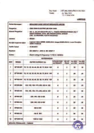
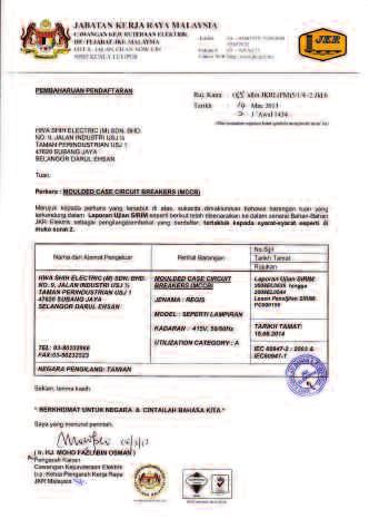
7 f e a t u r e company profile Since our inception in 1974, our company specializes in manufacturing low voltage circuit breakers and have a reputation of producing products of consistent quality and high reliability. Our manufacturing facilities are certified to the international quality standards of ISO 9001, while our products are certified by ASTA Certification Services UK and SIRIM QAS International. With such high standards, our range of circuit breakers are able to meet your highest demands for quality, safety and reliability. 6
8 SIRIM QAS certification 7

9 f e a t u r e SIRIM QAS certification 8
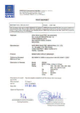
10 SIRIM QAS certification 9

11 f e a t u r e SASO certification ICS = ICU % 10


12 NF series circuit breakers The demand for economical and high performance circuit breakers is ever increasing in the global market. The NF series circuit breakers provide a simple and reliable solution to meet this global demand where quality, performance and compliance are required. The NF series circuit breakers have been engineered to provide effective protection to low voltage power distribution systems. The NF series is a complete range of MCCB s from 10A to 1200A with 1, 2, 3 and 4 pole versions. An extensive range of electrical accessories is also available. double repulsion breaking method The double repulsion method uses a reverse-loop of current (I) flowing in essentially opposite directions (see figure). This creates a repulsion action and results in a greater opening force (Fm) between the fixed and moving contacts. This force also assists to rapidly extinguish the arc, thereby causing the moving contacts to open faster. A faster breaking time is achieved with this design. moving contacts fixed contact 11


13 f e a t u r e double number of contact coppers For the NF600 and above circuit breakers, double moving contacts are used instead of a single contact. This additional moving contact improves the short circuit breaking performance and reduces contact wear. double moving contacts in NF1200 materials of the NF series 12 The design of the NF series circuit breakers makes it suitable to be used in hot and humid climates. The material used for the circuit breaker casing consists of synthetic resins reinforced with glass fibers. Furthermore, the metal parts used in the breakers are chemically treated to protect against corrosion. The external copper terminals are tin-plated to prevent oxidation.

14 method of installation The NF series circuit breakers can be installed in vertical or horizontal position without any impact on its performance or de-rating of characteristics. horizontal vertical MCCB cross sectional area D C E B F A Parts Index for cross-sectional area of MCCB A MCCB casing made of high-impact BMC material reinforced with glass fibres, providing a safe and strong housing in the event of breaking high-fault currents. B Trip-free mechanism ensuring positive operation and isolation suitability. Designed for long service life and high number of operating cycles. Metal parts in mechanism are chemically treated to withstand harsh tropical weather conditions. C Arc chutes with predefined steel plates arrangement, provide high breaking capabilities. D Fixed and moving contacts utilizing the reverse loop current method, creates a repulsion force thus rapidly extinguishing the arc. E Common trip mechanism to ensure breaking of all poles even when the fault occurs at a particular pole. F Trip release consists of thermal (bi-metal) and magnetic devices suitable for use in AC or DC supply voltages. positive indication & operation The circuit breaker operating handle is designed to indicate the exact position of its moving contacts. Its trip-free operating mechanism cannot indicate that the breaker is ON if the moving contacts are in the OFF position. If the breaker trips due to an electrical fault or overload the handle will be in between the ON and OFF position. This is the TRIP position. To switch the breaker ON after tripping, the handle position must be switched to OFF position first and so to reset the breaker and then switch to the ON position. 13


15 f e a t u r e suitability for isolation In compliance with IEC standard, NF series circuit breaker guarantees no leakage currents and over-voltage withstand between the supply and load terminals when its moving contacts are in the open position. test trip button isolation compliance with standards 14 The NF series circuit breakers have been designed to meet international standards, complying with the following standards: 1. IEC : International Electro 8. SEC Distributors: Saudi Electricity Committee Standard Company, Distribution Materials 2. BSEN : British Standard Specifications Prequalified Manufacturer European Norm 9. SASO: Saudi Standards, Metrology & 3. JIS C : Japan Industrial Standard Quality Organization 4. GB : China Standard 10. Housing & Development Board, Singapore 5. CNS : Taiwan Standard 11. Ministry of Electricity & Water, Kingdom 6. CE: Conformity European of Bahrain 7. SIRIM: Malaysia 12. Jabatan Perkhidmatan Elektrik Kementerian Pembangunan, Negara Brunei Darussalam
16 selection quick & easy table Rated Current In (A) 10 Interrupting Capacity Icu (ka) Sym at 415 Vac NF-MA NF-GP NF-MA NF-HA NF-L NF-GP NF2-GP NF2-MA NF2-HA NF2-L NF400-GP NF400-HA NF400-L NF600-GP NF600-HA NF600-L NF800-GP NF800-HA NF800-L NF1200-HA 15
 690 690 690 Rated Impulse withstand Voltage: U imp (kv) 8 8 8 8 8 8 8 8 8 Rated Ultimate")

17 p o w e r d i s t r i b u t i o n technical details electrical characteristics model Code NF NF NF2 Ampere Frame (AF) AF AF 2AF Rated Current: In (A) at Ambient Temp C Number of Poles Available Rated Insulation Voltage: U i(v) Rated Impulse withstand Voltage: U imp (kv) Rated Ultimate Short Circuit Breaking Capacity: I cu (ka) MA GP MA HA L GP MA HA L 690V V V IEC V V V V DC 2V Rated Service Short Circuit Breaking Capacity: I cs = % I cu Rated Short Circuit Breaking Capacity: (ka) 600V JIS C (sym) 440V 380V V DC 2V Suitable for Isolation Utilization Category A A A A A A A A A Pollution Degree No. of Electrical Operations Notes: - denotes available.
 690 690 690 Rated Impulse withstand Voltage: U imp (kv) 8 8 8 8 8 8 8 Rated Ultimate Short Circuit Breaking Capacity: I cu (ka)")
 600V 18 30 18 30 30 JIS C 8201-2 (sym) 440V 380V 25 65 30 25 65 30 220V 85 125 85 125 85 DC 2V")
18 technical details electrical characteristics model Code NF400 NF600 & NF800 NF1200 Ampere Frame (AF) 400AF 800AF 1200AF Rated Current: In (A) at Ambient Temp C & Number of Poles Available Rated Insulation Voltage: U i(v) Rated Impulse withstand Voltage: U imp (kv) Rated Ultimate Short Circuit Breaking Capacity: I cu (ka) GP HA L GP HA L HA 690V V V IEC V V V V DC 2V Rated Service Short Circuit Breaking Capacity: I cs = % I cu Rated Short Circuit Breaking Capacity: (ka) 600V JIS C (sym) 440V 380V V DC 2V Suitable for Isolation 17 Utilization Category A A A A A A A Pollution Degree No. of Electrical Operations Notes: - denotes available.
19 p o w e r d i s t r i b u t i o n technical details electrical characteristics model Code NF-MA NF2-MA 37-SDMS-01 NF400-HA NF600-HA Ampere Frame (AF) AF 2AF 400AF 600AF Rated Current: In (A) at Ambient Temp 55 C Number of Poles Available Rated Insulation Voltage: U i(v) Rated Impulse withstand Voltage: U imp (kv) Rated Ultimate Short Circuit Breaking Capacity: I cu (ka) IEC V V V Rated Service Short Circuit Breaking Capacity: I cs = % I cu Suitable for Isolation Utilization Category A A A A Pollution Degree No. of Electrical Operations Notes: - denotes available. 18
 7 7 7 Rated Impulse withstand Voltage: U imp (kv) 8 8 8 Rated Ultimate Short Circuit Breaking")
20 technical details electrical characteristics model Code 37-SDMS SDMS SDMS-02 NF800-HA NF2-MA NF400-HA Ampere Frame (AF) 800AF 2AF 400AF Rated Current: In (A) at Ambient Temp 55 C Number of Poles Available Rated Insulation Voltage: U i (V) Rated Impulse withstand Voltage: U imp (kv) Rated Ultimate Short Circuit Breaking Capacity: I cu (ka) IEC V V V Rated Service Short Circuit Breaking Capacity: I cs = % I cu Suitable for Isolation Utilization Category A A A Pollution Degree No. of Electrical Operations Notes: - denotes available. 19
21 p o w e r d i s t r i b u t i o n technical details mechanical characteristics & accessories Width Length Depth Accessories a aa b * ^ bbb bb c ca model Code CL ON LOCKED OFF aa a UNLOCKED bb Without Terminal Cover b (mm) c ca Type of Terminals No of Mechanical Operations Weight (kg) Operating Handle Lock Terminal Covers Mounting Screws Phase Barrier Cable Lug Terminal Shrouds 37-SDMS-01 NF-MA NF2-MA NF400-HA stirrup stirrup saddle NF600-HA saddle Width Length Depth Accessories a aa b * ^ bbb bb c ca model Code CL ON aa a UNLOCKED LOCKED OFF bb Without Terminal Cover b (mm) c ca Type of Terminals No of Mechanical Operations Weight (kg) Operating Handle Lock Terminal Covers Mounting Screws Phase Barrier Cable Lug Terminal Shrouds 37-SDMS SDMS SDMS-02 NF800-HA saddle saddle NF2-MA stirrup - NF400-HA * without Terminal Cover; ^ with Terminal Cover. Notes: - denotes available.
22 technical details thermomagnetic trip release model Code NF NF NF2 Ampere Frame (AF) Rated Ultimate Short Circuit Breaking Capacity: I cu (ka) Fixed thermal, Fixed Magnetic 10 x Ith Fixed thermal, Adjustable Magnetic AF MA AF 2AF GP MA HA L GP MA HA L mechanical characteristics Number of Poles (P) a b c (80) (80) 68 ca (102) (104) 92 bb aa Type of Terminals M5 clamp terminal screw M8 screw M8 screw No of Mechanical Operations Weight (kg) (1.2) (1.6) 1.9 accessories Shunt Trip Device Under Voltage Trip Device Auxiliary Switch Alarm Switch Auxiliary + Alarm Switch 21 Rotary Handle Notes: All L-type breakers are only available in the 3-pole version; ( ) denotes for L-type. - denotes available; however, all accessories are not available for 1-pole models.
23 p o w e r d i s t r i b u t i o n technical details thermomagnetic trip release model Code NF400 NF600 & NF800 NF1200 Ampere Frame (AF) Rated Ultimate Short Circuit Breaking Capacity: I imp (ka) Fixed thermal, Fixed Magnetic 10 x Ith Fixed thermal, Adjustable Magnetic 400AF GP HA L 800AF 1200AF GP HA L HA mechanical characteristics Number of Poles (P) a b c ca bb aa Type of Terminals M12 Bolt M12 Bolt M12 Bolt No of Mechanical Operations Weight (kg) 5.5(6.0) (11) accessories Shunt Trip Device Under Voltage Trip Device Auxiliary Switch Alarm Switch 22 Auxiliary + Alarm Switch Rotary Handle Notes: All L-type breakers are only available in the 3-pole version; ( ) denotes for L-type. - denotes available.
24 c h a r a c t e r i s t i c s NF-MA characteristic curves tripping curve temperature characteristic ~A Rated ambient A~30A NF-GP, MA & HA characteristic curves tripping curve temperature characteristic Instantaneous trip 23
25 c h a r a c t e r i s t i c s NF2-GP, MA & HA tripping curve characteristic curves temperature characteristic 130 Current rating (%) Rated ambient 80 Rated ambient C Ambient temperature ( C) NF400-GP & HA tripping curve characteristic curves temperature characteristic 24
26 NF600/800-GP & HA tripping curve characteristic curves temperature characteristic Frame size: 800AF NF600 NF800 NF1200-HA tripping curve characteristic curves temperature characteristic 25
27 c h a r a c t e r i s t i c s NF-L characteristic curves tripping curve NF2-L characteristic curves tripping curve 26
28 NF400-L characteristic curves tripping curve NF600/800-L characteristic curves tripping curve 27
29 p h y s i c a l d i m e n s i o n s & m o u n t i n g h o l e s NF-MA front connection 2-pole 3-pole 28 2-pole 3-pole
30 NF-GP, MA & HA front connection 4-pole 2-pole 3-pole 2-pole 3-pole 4-pole 29
31 p h y s i c a l d i m e n s i o n s & m o u n t i n g h o l e s NF2-GP, MA & HA front connection 4-pole 3-pole 30 3-pole 4-pole
32 NF400-GP & HA front connection 4-pole 3-pole 3-pole 4-pole 31
33 p h y s i c a l d i m e n s i o n s & m o u n t i n g h o l e s NF600/800-GP & HA front connection 4-pole 3-pole 32 3-pole 4-pole
34 NF1200-HA front connection Insulation barrier (removable) Insulation barrier (removable) Bolt M12x 115 Mounting hold Mounting hold Conductor N Neutral Pole Pole 3 Pole R M8 Screw or 10mm 33 3-pole 4-pole
35 p h y s i c a l d i m e n s i o n s & m o u n t i n g h o l e s NF-L front connection 3-pole 3-pole NF2-L front connection 3-pole 3-pole 34
36 NF400-L front connection 3-pole 3-pole NF600/800-L front connection 3-pole 3-pole 35
37 p h y s i c a l d i m e n s i o n s & m o u n t i n g h o l e s 37-SDMS-01 NF-MA front connection Breaker ON UNLOCKED OFF 22 LOCKED Ø 8.5 Ø M4x0.7 thread or 5 mm-dia. hold 37-SDMS-01 NF2-MA front connection 24.5 Breaker ON UNLOCKED 200 LOCKED OFF Ø 7 Ø M4x0.7 thread or 5 mm dia. hold 36
38 37-SDMS-01 NF400-HA front connection Breaker ounting hold ON UNLOCKED OFF 400 LOCKED M20 Socket Set Screw 194 OFF Ø Ø 7 M10 Hex. head Screw M6 Screw 7mm dia SDMS-01 NF600-HA front connection 210mm (Max.) Breaker ON OFF 630 OFF UNLOCKED LOCKED (Max. without cover) 102 Ø 4 15± Ø Ø mm (Max.) t 0A: t= 6 m/m 630A: t= 8 m/m 800A: t= 12 m/m 70 M6 Screw or 7mm dia. hol 37
39 p h y s i c a l d i m e n s i o n s & m o u n t i n g h o l e s 37-SDMS-01 NF800-HA front connection 210mm (Max.) Breaker ON OFF 800 OFF UNLOCKED LOCKED (Max. without cover) ± Ø 4 Ø 8 Ø mm (Max.) t 0A: t= 6 m/m 630A: t= 8 m/m 800A: t= 12 m/m 70 M6 Screw or 7mm dia. hol 38
40 37-SDMS-02 NF400-HA front connection Phase Barrier Terminal Shroud Breaker Mounting hold ON OFF Terminal Shroud 194 OFF 47 Ø 12.5 Ø 7 M10 Hex. head screw M6 Screw or 7mm dia. hold 37-SDMS-03 NF2-MA front connection Phase Barrier Terminal Shroud M8 Hex. socket head screw 24.5 Breaker Terminal Shroud ON OFF Ø 7 Ø 4.5 M8 Hex. socket head screw M4x0.7 or 5 mm 39


41 a c c e s s o r i e s phase insulation barriers Inter phase barriers are provided as standard. The use of the inter phase barriers is necessary to increase the clearance distances between phases to prevent electrical faults during the operation of the circuit breaker. Model NF NF NF2 a b NF NF a dimensions of phase barrier insulators in mm NF NF top b electrical accessories & shunt trip All electrical accessories supplied for the breaker are prewired. Accessories such as Shunt Trip, Under Voltage Trip, Alarm Switch, Auxiliary Switch and combination Alarm and Auxiliary Switch can be fitted into the breaker accessory compartments. Please refer to the table in page 31 for the accessories installation guide. Shunt Trip Device The Shunt Trip device opens the circuit breaker by means of an electrical signal. Voltages between 70% and 110% of the coil voltage rating will operate the shunt trip device. 40 All Shunt Trip devices are factory fitted with a cut-off supply switch.
 < 15 < 15 < 15 8 to 15 8 to 15 8 to 15 8 to 15 Note: Other voltages can be supplied on demand.")
42 / 60 Hz Coil Power Consumption (VA) Coil Voltage NF NF NF2 NF400 NF600 NF800 NF1200 AC (V) AC - 4 (200V) AC (330V) AC (4V) AC DC Trip Time (ms) < 15 < 15 < 15 8 to 15 8 to 15 8 to 15 8 to 15 Note: Other voltages can be supplied on demand. under voltage trip device The Under Voltage Trip device will open the circuit breaker contacts when the supply voltage to the coil drops below 70% of its voltage rating. After tripping, the circuit breaker can be closed manually again when the supply voltage is 85% of its coil voltage rating or more. The Under Voltage Trip device is always energized during normal conditions when supply voltage is healthy. Model AC Coil Voltage Consump (VA) Trip Time (ms) NF2 & below < NF to 30 NF to 30 NF to 35
 and normally closed (N.C.) positions. Auxiliary Switch - Provides breaker ON and OFF status information.")
43 a c c e s s o r i e s signaling switches The Signaling switches allow the breaker status information to be obtained remotely. The signaling switch consists of several dry contacts with both normally open (N.O.) and normally closed (N.C.) positions. Auxiliary Switch - Provides breaker ON and OFF status information. Auxiliary Switch Alarm Switch - Provides breaker TRIP status information. Auxiliary + Alarm Switch - Provides breaker ON, OFF and TRIP status information. Alarm Switch Please refer to the above circuit diagram for the switch terminal codes in order to obtain different contact positions, such as N.O. and N.C. to suit the application. rotary handle mechanism The breaker mounted rotary handle mechanism allows the user to easily switch the breaker ON by a rotating action. The rotary handle mechanism is equipped with a safety device that prevents the panel door from being open when the breaker is in ON position. A bypass screw is provided for manual intervention when breaker is in ON position. 42 Pad locking facility is available on the rotary handle. The handle can be pad locked when the breaker is in OFF position.
44 rotary handle external dimensions Figure (a) Figure (b) rotary handle drilling plan Figure (c) Figure (d) Figure (e) Type Breaker Type No of Pole Figure External Dimensions Drilling Plan Dimensions (mm) A B C D Mounting Screws AC-NF-RHN0 AC-NF-RHN1 AC-NF-RHN2 NF-MA NF-GP MA HA NF-L EG-MA HA NF2-GP MA HA NF2-L EG2-MA HA 3P 3P 4P 3P 4P a c e (116) 126 (145) M4 x 0.7 screw or ø 5 (X) breakers mounting screws (2pcs) (Y) operating handle mounting screws (2pcs) AC-NF-RHN3 AC-NF-RHN4 NF400-GP HA L NF600-GP HA L NF800-GP HA L NF1200-HA 3P 4P 3P 4P b d e M6 screw or ø 7 (X) (Y) breakers mounting screws (4pcs) 43 Note All rotary handles are supplied with M4 x 0.7 screws and self-tapping ø 5mm screws.

.")
 or more (8H + ) or more Right hinge H Less than 10 10 or more Right hinge X2")
45 a c c e s s o r i e s rotary handle appearance A direct rotating operating handle has a standard safety device which prevents the breaker from closing as long as the cover is open. It indicates the tripping of the breaker even in ON-lock position, but only in cases when a single padlock (35mm) is used. The degree of protection, in accordance with IEC529, is IP3X (or IP5X with provision of dustproof packing). The use of the rotary handle mechanism increases the IP rating of the breaker Type AC-NF-RHN0 to AC-NF-RHN2 AC-NF-RHN3 to AC-NF-RHN4 Left hinge H 0 or more 0 or more Center of hinge & Breaker Left hinge X1 (5H + ) or more (8H + ) or more Right hinge H Less than or more Right hinge X2 170 or more (5H + 120) or more 0 or more (4H + 70) or more The figure above shows the relationship between the hinge and breaker viewed from the load side of the breaker. 44
46 mounting position internal accessory MCCB models Accessories NF MA NF GP MA HA L NF2 GP MA HA L NF400 GP HA L NF600/800 GP HA L NF1200 HA Shunt Trip Coil (STC) R1 & 2 R1 & 2 R1 & 2 R1 & 2 R1 & 2 Under Voltage Trip (UVT) R1 & 2 R1 & 2 R1 & 2 R1 & 2 R1 & 2 Auxiliary Switch (AUS) L1 & L2 L1 & L2 L1, L2 L1, L2, L3 L1, L2, L3 Alarm Switch (ALS) L1 & L2 L1 & L2 L1, L2 L1, L2, L3 L1, L2, L3 Auxiliary + Alarm Switch (AAS) L1 & L2 L1 & L2 L1, L2 L1, L2, L3 L1, L2, L3 Notes 1) It is NOT possible to install both UVT and STC in the same MCCB. 2) For NF600 onwards, it is possible to install up to a maximum of 4 Auxiliary. Switches or 2 Alarm switches. 3) UVT requires a voltage module that is installed on the right side lead wire terminal. right side Accessory compartment slot markings left side L = Left compartment; R = Right Compartment 45
47 r e s i s t a n c e & p o w e r t a b l e internal resistance & power loss Type NF-MA NF-GP NF-MA NF2-GP NF2-MA NF400-GP NF600-GP NF800-GP In A Resistance uω Loss W Resistance uω Loss W Resistance uω Loss W Resistance uω Loss W Resistance uω Loss W Resistance uω Loss W Resistance uω Loss W Resistance uω Loss W 10A A 20A 30A 40A A A A A A A A A A A A A 300A 3A 400A A A A 800A
48 internal resistance & power loss Type NF-HA NF2-HA NF400-HA NF600-HA NF800-HA NF1200-HA In A Resistance uω Loss W Resistance uω Loss W Resistance uω Loss W Resistance uω Loss W Resistance uω Loss W Resistance uω Loss W 10A A A A A A A A 80A A A 1A 160A 175A 200A 225A A 300A 3A 400A A 600A A 800A A 1200A
49 r e s i s t a n c e & p o w e r t a b l e internal resistance & power loss Type NF-L NF2-L NF400-L NF600-L NF800-L In A Resistance uω Loss W Resistance uω Loss W Resistance uω Loss W Resistance uω Loss W Resistance uω Loss W 10A A A A A A A A 80A A A 1A 160A 175A 200A 225A A 300A 3A 400A A 600A A 800A
50 d c s h o r t c i r c u i t t a b l e DC voltage time constant 10ms or below Model Pole 48V Icu/Ics 125V Icu/Ics 2V Icu/Ics 400V Icu/Ics 5V Icu/Ics 600V Icu/Ics NF-MA / / / 8 15 / / / 4 6 / 3 NF-GP / / / / 8 15 / 8 15 / / / / 7 6 / 3 NF-MA / 25 / 25 / 25 / / / / / / 8 15 / 8 15 / 8 15 / 8 10 / 5 10 / 5 8 / 4 8 / 4 NF-HA / / / / 80 / / / / / / / / / / / 9 18 / 9 NF-L 3 1 / 75 / / / 18 NF2-GP / / / / 8 15 / 8 15 / / / / 4 6 / 3 NF2-MA / 25 / 25 / 25 / / / / / / 8 15 / 8 15 / 8 15 / 8 10 / 5 10 / 5 8 / 4 8 / 4 NF2-HA / / / / 80 / / / / / / / / / / / 9 18 / 9 NF2-L 3 1 / 75 / / / 18 NF400-GP / / / / / / / 8 13 / 8 10 / 5 10 / 5 NF400-HA 3 4 / / 80 / / / / / / / 9 18 / 9 NF400-L 3 1 / 75 / / / 18 NF600 / NF800-GP / / / / / / / 8 13 / 8 10 / 5 10 / 5 NF600 / NF800-HA 3 4 / / 80 / / / / / / / 9 18 / 9 49 NF800-L 3 1 / 75 / / / 18 NF1200-HA 3 4 / / 80 / / / / / / / 9 18 / 9
51 s e l e c t i o n t a b l e motor circuit protection 3-phase motor 400V 440V / 60Hz Motor Capacity [kw at 400/440] Motor Full-load Current [A] MCCB In [A] 10 Interrupting Capacity Icu (ka) Sym NF-MA NF-MA NF-HA NF-L NF-GP NF2-GP NF2-MA NF2-HA NF2-L NF400-GP NF400-HA NF400-L NF600-GP NF600-HA NF800-GP NF800-HA NF800-L
52 Short Circuit protection of electric motors The NF series circuit breakers are suitable to combine with motor starters. As defined in IEC standards, the starter switching device, usually a magnetic contactor, must be coordinated with the equipment capable of providing short circuit protection for circuit wiring/cables. The common starting methods for asynchronous squirrel-cage induction motors which the NF series can be used in combination are the direct-online-starters and star-delta-starters. The following selection tables, illustrating the above, shows the suitable breaker ratings that can accommodate motor starting currents. When more than one motor is connected to a branch circuit, the sum of the motor rated current equals to the rated current of the breaker. motor selection direct-online-starter Motor Ratings kw HP 1/4 1/2 3/ Motor Full-Load Current (A) ø 220V Rated Current (A) Wire Size (mm 2 ) Motor Full-Load Current (A) ø 380V Rated Current (A) Wire Size (mm 2 ) Motor Full-Load Current (A) ø 415V Rated Current (A) Wire Size (mm 2 ) Motor Ratings kw HP Motor Full-Load Current (A) ø 220V Rated Current (A) Wire Size (mm 2 ) Motor Full-Load Current (A) ø 380V Rated Current (A) Wire Size (mm 2 ) Motor Full-Load Current (A) ø 415V Rated Current (A) Wire Size (mm 2 ) Please note that the breaker selection shown in the tables are subjected to the following: only 1 motor to be installed in the circuit and the starting current is less than 6 times of motor full load current.
 Wire Size (mm 2 ) 600 200 700 325 800 325 Motor Full-Load Current (A) 202 238 290 360 4 570 3 ø 380V Rated Current (A) Wire Size (mm 2 ) 400 1 400 200 0 200 600 800 0 200 325 325 Motor")
53 s e l e c t i o n t a b l e motor selection direct-online-starter Motor Ratings kw HP Motor Full-Load Current (A) ø 220V Rated Current (A) Wire Size (mm 2 ) Motor Full-Load Current (A) ø 380V Rated Current (A) Wire Size (mm 2 ) Motor Full-Load Current (A) ø 415V Rated Current (A) Wire Size (mm 2 ) motor selection star-delta-starter Motor Ratings kw HP Motor Full-Load Current (A) ø 220V Rated Current (A) Wire Size (mm 2 ) Motor Full-Load Current (A) ø 380V Rated Current (A) Wire Size (mm 2 ) Motor Full-Load Current (A) ø 415V Rated Current (A) Wire Size (mm 2 ) Please note that the breaker selection shown in the tables are subjected to the following: only 1 motor to be installed in the circuit and the starting current is less than 6 times of motor full load current.
54 motor selection star-delta-starter Motor Ratings kw 90 HP Motor Full-Load Current (A) ø 220V Rated Current (A) Wire Size (mm 2 ) Motor Full-Load Current (A) ø 380V Rated Current (A) Wire Size (mm 2 ) Motor Full-Load Current (A) ø 415V Rated Current (A) Wire Size (mm 2 ) Please note that the breaker selection shown in the tables are subjected to the following: only 1 motor to be installed in the circuit and the starting current is less than 6 times of motor full load current. installation Model NF NF-2 NF NF Operating Voltage U<440V U<600V U<440V U<600V U<440V U<600V U<440V U<600V safety distance requirements Insulation, Insulated Bars or Painted Sheetmetal (mm) A B1 B Bare/Unpainted Sheetmetal (mm) A B1 B
55 s e l e c t i o n t a b l e terminal-tightening torque To ensure the correct operation of the MCCB, it is essential to make a proper cable or busbar termination to the MCCB. It is recommended that the supplied screws be used to connect the cables or busbars to the breaker terminals and tightened to the torque, as shown in the table below. terminals for cable lugs connection Cable size mm 2 tightening range* Nm Bolt/Screw Screw Model Min Max I II Size Type NF 1.6 ø ~ 2.0 N/A M5 screw Pan head NF 1.6 ø 2.5 ~ 3.5 N/A M8 screw Screw NF ~ 3.5 N/A M8 screw Screw NF x N/A 10 ~ 14 M12 bolt x 2 Bolts NF600 2 x 1 2 x 200 N/A 10 ~ 14 M12 bolt x 2 Bolts NF800 N/A N/A N/A N/A N/A N/A NF1200 N/A N/A N/A N/A N/A N/A terminals for copper busbar connection Copper busbar size mm 2 tightening range* kgf-cm Bolt/Screw Model Max t = Max w = I II Size NF ~ 2.0 N/A M5 screw NF ~ 3.5 N/A M8 screw NF ~ 3.5 N/A M8 screw NF N/A 10 ~ 14 M12 bolt x 2 NF N/A 10 ~ 14 M12 bolt x 2 NF N/A 10 ~ 14 M12 bolt x 2 54 NF1200 * Note Copper busbar N/A 10 ~ 14 Caution 1) Do not over tighten. If the tightening torque is exceeded, bolts/screws and copper bars may be damaged. 2) Failure to secure a terminal connection may cause an electrical fault. Make sure all terminal connections are tightly secured. M12 bolt x 2
56 c o n n e c t i o n d a t a terminal-cable & copper busbar sizes MCCB Rated Current In (A) ISO Square (mm 2 ) CNS Standard Square (mm 2 ) UL Standard AWG or kcmil at 75 C 8 In > ø 14 AWG 12 In > ø 14 AWG 15 In > ø 14 AWG 20 In > ø 12 AWG 25 In > AWG 32 In > AWG In > AWG 65 In > AWG 85 In > AWG In > AWG 115 In > 35 2 AWG 130 In > AWG 1 In > /0 AWG 175 In > /0 AWG 200 In > /0 AWG 225 In > /0 AWG 2 In > MCM 275 In > MCM 300 In > MCM 3 In > MCM 400 In > x 2 x 3/0 AWG 0 In > x 1 2 x 1 2 x 2 MCM 630 In > 0 2 x x x 3 MCM 800 In > x x 2 3 x 300 MCM 0 In > x (30 x 5) 2 x (30 x 5) 2 x 2 MCM In > 0 2 x (40 x 5) 2 x (40 x 5) 2 x 3 MCM 800 In > x ( x 5) 2 x ( x 5) 3 x 300 MCM
 at Ambient Temperature: C 240 / 415 240 / 415 240 / 415 10 15 20 30 40 60 75 80 10 15")

57 M C B BHQ series fixed type Ampere Frame (AF) Model Code BHQ-1 BHQ-2 BHQ-3 Number of Pole (P) Rated Voltage: Ue Vac Rated Current: In (A) at Ambient Temperature: C 240 / / / Rated Ultimate Short Circuit Breaking Capacity: I cu (ka) IEC V/415V 6 / 6 6 / 6 6 / 6 a b Weight c ca bb aa kg
 at Ambient Temperature: C 240 / 415 240 / 415 240 / 415 10 15 20 30 40 60 75 80 10 15 20 30 40")

58 BHP series plug-in type Ampere Frame (AF) Model Code BHP-1 BHP-2 BHP-3 Number of Pole (P) Rated Voltage: Ue Vac Rated Current: In (A) at Ambient Temperature: C 240 / / / Rated Ultimate Short Circuit Breaking Capacity: I cu (ka) IEC V/415V 6 / 6 6 / 6 6 / 6 a a aa ca c b c b Weight ca bb aa kg
59 M C B c h a r a c t e r i s t i c s & d i m e n s i o n s BHQ & BHP series operating characteristics BHQ & BHP series temperature characteristics 58
60 BHQ series fixed type front connection 1-pole 2-pole 3-pole BHP series plug-in type front connection 59 1-pole 2-pole 3-pole
61 60 N O T E S
62 what is quality? We define quality as products having the highest level of reliability, performance and design. Our aim for quality is to meet the requirements of other global markets and to exceed the current international standards. With our in-house design and development team, our range of products are currently manufactured in accordance and compliance to various international standards. our road to quality Manufacturer Hwa Shih Electric Industrial Co Ltd 14, 16 Lane 2, Pa Teh Road, Yinko District, New Taipei City, Taiwan R.O.C. Tel : Fax : hwashih@ms61.hinet.net
3 - Protection components Circuit-breakers
 Contents - Protection components Circuit-breakers for the motor protection Selection guide..............................................page /2 Thermal-magnetic motor circuit-breakers Selection guide..............................................page
Controls Contactors and Contactor Assemblies Special Applications
 Controls Contactors and Contactor Assemblies Special Applications Price groups 1B, 1H /2 Introduction More information can be found on the Internet: see the opening information, page 13 - Contactors for
Safety switches with slotted hole lever
 Safety switches with slotted hole lever Selection diagram C1 C C C4 C5 Straight slotted hole lever Slotted hole lever at the left Slotted hole lever at the right (without bend) Slotted hole lever at the
J7M-AM/-BM. Motor--protective circuit--breaker system. J7M -BM System IEC 947, EN IEC 947, EN 60947
 Motor--protective circuit--breaker system J7M -AM System Rated operational current 25 A. Switching capacity up to 10 A, 100 ka/415 V. Switching capacity 16 A, 20 A, 25 A, 16 ka/415 V. Fixed short--circuit
TeSys circuit-breakers Thermal-magnetic motor circuit-breakers types GV2, GV3 and GV7
 Presentation Thermal-magnetic motor circuit-breakers types GV, GV and GV7 GV-ME, GV-P, GV-ME and GV7-R motor circuit-breakers are -pole thermal-magnetic circuit-breakers specifically designed for the control
UTE100 SELECTION GUIDE CATALOG NUMBERING [PRODUCT SELECTION] UTE100 NT FMU 100A 3P LL LSIS UL MCCB
![UTE100 SELECTION GUIDE CATALOG NUMBERING [PRODUCT SELECTION] UTE100 NT FMU 100A 3P LL LSIS UL MCCB](/thumbs/77/75881930.jpg "UTE100 SELECTION GUIDE CATALOG NUMBERING [PRODUCT SELECTION] UTE100 NT FMU 100A 3P LL LSIS UL MCCB") PRODUCT CATALOG SUSOL SUPER SOLUTION SELECTION GUIDE UTE00 CATALOG NUMBERING [PRODUCT SELECTION] UTE00 NT FMU 00A 3P LL UL SERIES & FRAME: Susol 00AF PERFORMANCE Rating 80% 00% ka SUFFIX UL : UL 20/ 240Vac
PRODUCT CATALOG SUSOL SUPER SOLUTION SELECTION GUIDE UTE00 CATALOG NUMBERING [PRODUCT SELECTION] UTE00 NT FMU 00A 3P LL UL SERIES & FRAME: Susol 00AF PERFORMANCE Rating 80% 00% ka SUFFIX UL : UL 20/ 240Vac
Page 13-2 Page Page 13-7
 Page -2 Page -6 MINIATURE CIRCUIT BREAKERS UP TO 63A 1P, 1P+N, 2P, 3P and 4P versions IEC rated current In: 1-63A IEC short-circuit capacity Icn: 10kA (6kA for 1P+N) Trip characteristic curve: Type B,
ZUCCHINI MS - LOW TO MEDIUM POWER BUSBAR
 ZUCCHINI MS - LOW TO MEDIUM POWER BUSBAR The flexibility of the Zucchini MS range during planning and installation makes it ideal for frequently changing requirements in small to medium sized commercial
FM series position switches
 FM series position switches Selection diagram 0 08 0 A A 0 A 0 External rubber gasket External rubber gasket External rubber gasket External rubber gasket 0 69 Round rod, stainless steel Square rod Glass
Capacitor Switching Contactors
 Capacitor Switching D385E51 Technical catalogues and news under: www.benedict.at Motor-Starter Mini- Overload Relays Capacitor Switching Motor-Starters Modular Circuit Breakers M4-32T... up to 32A M4-32R..
TeSys contactors. TeSys D contactors. IEC/EN , IEC/EN , UL 508, CSA C22.2 n 14. Protection against direct fi nger contact IP 2X
 Characteristics Contactor type LC1 D09 D18 DT20 and DT25 Environment Rated insulation voltage (Ui) Conforming to IEC 097--1, overvoltage category III, degree of pollution: 3 Conforming to UL, CSA V 00
Characteristics 5 TeSys k contactors and reversing contactors
 90 Characteristics contactors k contactors and reversing contactors Environment characteristics Conforming to standards IEC 60947, NF C 63-110, VDE 0660, BS 424 Product certifications LCp and LPp K06 to
PKZ 2 Manual Motor Protectors Technical Data
 08/066 PKZ 2 Manual Motor Protectors General Standards UL 508, CSA C 22.2 No. 14, IEC/EN 60 947, VDE 0660 GL, LR, DNV, PRS, BV, RINA, RS, EZU, MEEI Climatic proofing Damp heat, constant, to IEC 60 068-2-3
LC2D09BD. Main. Device short name. Utilisation category. Poles description Pole contact composition
 Product datasheet Characteristics Main Range Product name Product or component type Device short name Contactor application Utilisation category Device presentation Poles description Pole contact composition
Motor-protective circuit-breaker, 3p, Ir=40-50A, screw connection. Product range PKZM4 motor protective circuit-breakers up to 65 A
 DATASHEET - PKZM4-50 Delivery program Motor-protective circuit-breaker, 3p, Ir=40-50A, screw connection Part no. PKZM4-50 Catalog No. 222355 Eaton Catalog No. XTPR050DC1NL EL-Nummer 0004355161 (Norway)
Catalog 200 Contactors up to 115 A Motor Starters up to 55 kw 03/2009
 Catalog 00 Contactors up to 5 A Motor Starters up to 55 kw 03/009 Kraus & Naimer The development of the Blue Line rotary switch, contactor and motor starter product ranges is based on more than hundred
LC1D12BL TeSys D contactor - 3P(3 NO) - AC-3 - <= 440 V 12 A - 24 V DC coil
 - AC-3 - <= 440 V 12 A - 24 V DC coil") Characteristics TeSys D contactor - 3P(3 NO) - AC-3 -
Characteristics TeSys D contactor - 3P(3 NO) - AC-3 -
SIRCO M UL98 Load break switches standards UL and CSA 30 to 100 A
 The solution for Load break switches > Power distribution. sircm_100_a_1_cat Rotary switch SIRCO M 3 x 100 A Strong points > Total integration. > Wide range of accessories. > Upgradeability. > Compliance
Miniature circuit-breakers S 280 UC series. System pro M. Technical data
 Technical data 11 Robbie Rd. / Avon, MA 02322 T:(508)513-1000 F:(508)513-1100 70 Ernest St. / Providence, RI 02905 T:(401)781-7100 www.controllerservice.com System pro M Prior to connection of aluminum
LC1D32BD TeSys D contactor - 3P(3 NO) - AC-3 - <= 440 V 32 A - 24 V DC coil
 - AC-3 - <= 440 V 32 A - 24 V DC coil") Characteristics TeSys D contactor - 3P(3 NO) - AC-3 -
Characteristics TeSys D contactor - 3P(3 NO) - AC-3 -
Position switches FM series
 B Position switches FM series Selection diagram 0 08 0 A A 0 A 0 external rubber gasket external rubber gasket external rubber gasket external rubber gasket 69 stainless steel round rod square rod fiber
(1,5 modules per pole)
") 87045 LIMOGES Cedex Telephone: +33 5 55 06 87 87 FAX: +33 5 55 06 88 88 DX 3 MCB 25kA 80A to 125A CONTENTS PAGES 1. Description - Use... 1 2. Range... 1 3. Overall dimensions... 1 4. Preparation - Connection...
87045 LIMOGES Cedex Telephone: +33 5 55 06 87 87 FAX: +33 5 55 06 88 88 DX 3 MCB 25kA 80A to 125A CONTENTS PAGES 1. Description - Use... 1 2. Range... 1 3. Overall dimensions... 1 4. Preparation - Connection...
DRIVIA cabinets LIMOGES Cedex France 1. DESCRIPTION, USE 3. DIMENSIONS 2. RANGE, CAT. NO. EQUIVALENCE TABLE
 87045 LIMOGES Cedex France Tel: (+33) 05 55 06 87 87 Fax: (+33) 05 55 06 88 88 DRIVIA cabinets CONTENTS NTS PAGES 1. Description, use....1 2. Range, equivalence table...1 3. Dimensions...1 4. General characteristics...2
SIRCO M UL 98 Load break switches standards UL and CSA from 30 to 100 A
 Load break switches standards UL and CSA The solution for Load break switches sircm_1_a_1_cat > Power distribution Strong points Function Rotary switch SRCO M 3 x 1 A SRCO M load break switches are compact
Solid State Relays 1- and 2 Pole SOLITRON With Integrated Heatsink
 Solid State Relays 1- and 2 Pole SOLITRON With Integrated Heatsink AC Solid State Contactor, 1- and 2 poles Zero switching for heating and motor applications Instant-on switching Rated operational current
Circuit Breakers. Excerpt from Master Catalogue. Circuit Breakers. Specifically For You
 Circuit Breakers Excerpt from Master Catalogue Circuit Breakers Specifically For You Hydraulic-magnetic technology ensures reduced nuisance tripping with temperature variance Always holds 00% rated current
Electronic Circuit Breaker with reset input ESS20-1..
 Electronic Circuit Breaker with reset input ESS0-.. Description The special device ESS0-.. is a further extension of the product line electronic circuit breakers. Type ESS0-.. has a width of only. mm and
Motor Protection Circuit Breaker Series 8146/5-V27
 www.stahl.de > For protection of Ex e and Ex d motors > Protects electric lines and plant equipment > Thermal overcurrent release, adjustable, phase failure sensitive > Electromagnetic quick release >
LC2D09BL REVERSING CONTACTOR 575VAC 9A IEC
 Product datasheet Characteristics LC2D09BL REVERSING CONTACTOR 575VAC 9A IEC Price* : 107.62 GBP Main Range Product name Product or component type Device short name Contactor application Utilisation category
IGS IGS-M-EL-22(1) Contactors APPROVED. Iranian Gas Standards
 Contactors APPROVED. Iranian Gas Standards") APPROVED IGS Iranian Gas Standards Contactors. Fax:(9821)-8131-5679 --. /012 34-52673892 :;395- 8? /@A7 B;CD /E FGH 34-52673892I2
APPROVED IGS Iranian Gas Standards Contactors. Fax:(9821)-8131-5679 --. /012 34-52673892 :;395- 8? /@A7 B;CD /E FGH 34-52673892I2
Electronic Circuit Breaker ESS20-0..
 Description Electronic circuit breaker type ES-0.. is designed to ensure selective disconnection of individual loads in systems which are powered by a DC 4 V switch-mode power supply. DC 4 V power supplies,
Modeion OTHER ACCESSORIES OF MOULDED CASE CIRCUIT BREAKERS
 OTHER ACCESSORIES OF MOULDED CASE CIRCUIT BREAKERS P Other accessories DELAY UNIT Type Product code Description Weight [kg] Package [pc] BZ-BX-X230-A 36696 enables to delay the undervoltage release tripping
LR Position Switches TECHNICAL DATASHEET
 TECHNICA DATASHEET Position Switches Technopolymer housing, one conduit entry Protection degree IP6 according to EN 69 contact blocks available actuators available M assembled connector versions Silver
Top wiring permanent magnet latching For non-motor loads, lighting, heating NEMA sizes to 300 A 2-, 3-, and 4-pole configurations
 Bulletin LP NEMA AC Permanent Magnet-Latching Lighting Contactors Product Overview/Product Selection/Wiring Diagram A, -Pole Open Type without Enclosure Bulletin LP Top wiring permanent magnet latching
Modular equipment. Presentation, standards. Standard contactors TeSys GC
 Presentation, standards Standard contactors TeSys GC Presentation TeSys GC contactors are designed for use in modular panels and enclosures. These contactors feature: b Easy installation v quick clip-on
Industrial Controls. Catalog IC SIRIUS. Answers for industry.
 Industrial Controls Catalog IC 10 2012 SIRIUS Answers for industry. Contactor Relays Siemens AG 2012 Overview Standards IEC 60947-1, EN 60947-1, IEC 60947--1, EN 60947--1 The 3TH42 and 3TH43 contactor
References 1 for asynchronous motors 1
 References 1 DF56902 DF5690 DF56901 ATS 01N10FT ATS 01N212QN ATS 01N20LY for 0.7 to kw motors power Nominal current Reference (2) Weight Single phase -phase 20 V 210 V 20 V 20 V 400 V 460 V kw HP kw HP
Mini Contactors. Mini Contactor Relays 4-pole 8 Auxiliary Contact Blocks. Interface Contactor Relays. Mini Contactors 10 Auxiliary Contact Blocks
 Mini Contactors Mini Contactor Relays 4-pole 8 Auxiliary Contact Blocks Interface Contactor Relays Mini Contactors 10 Auxiliary Contact Blocks Mini Contactors With Fast On Tab Connectors 12 Mini Contactors
Open Type Without Enclosure
 Bulletin L NEMA AC Electrically Held Lighting Contactors Product Selection Top Wiring for Non-Motor and Lighting Loads Tungsten Lamp Loads (Max. V Line, V Load) Maximum Continuous Ampere Ratings [A] General
Components for safety applications
 Metal, turret head, types CS-A, CS-C and CS-E Double insulated, turret head, types CS-PA, CS-TA and CS-TE Presentation Metal, types CS-A, CS-C, CS-E Switches with or without locking of the actuator Pages
technical information
 technical information protection devices 192 circuit protection principle 194 circuit breakers characteristics 200 moulded case circuit breakers (MCCB) 205 prospective fault current 208 selectivity and
E-STOP relays, safety gate monitors
 Safety relay for monitoring E-STOP pushbuttons, safety gates and light barriers. Approvals Unit features Positive-guided relay outputs: 3 safety contacts (N/O), instantaneous 1 auxiliary contact (N/C),
SB 50 Connectors - up to 120 amps
 Connectors - up to 120 amps Based off the design pioneered by Anderson in 1953, APP s two pole SB connectors set the standard for DC power distribution and battery connections. connectors feature a one
NEMA Contactor and Starter Specifications
 Technical Data NEMA Contactor and Starter Specifications Bulletins 00, 0, 0, 0, 06, 06X, 07, 07X, 09,,, E/F/G, E/F/G Topic Page Specifications Electrical Ratings Mechanical Ratings, Construction, Environmental
Technical features table for miniature circuit-breakers SH 200 Series
 Technical features table for miniature circuit-breakers SH 00 Series Standards Poles Tripping characteristics I n A frequency f Hz insulation voltage U i acc. to IEC/EN 60664-1 V Overvoltage category Pollution
C20.en. Power contactors for AC and DC CT1115 and CT1130. Connect - Contact - Control
 Caution: Device contains unprotected active pieceparts, Device contains unprotected non-active pieceparts, which may interact with active pieceparts, Touch only after adhering to corresponding safety regulations!
Type: DILM80(110V50HZ,120V60HZ) Article No.: Sales text Contactor,37kW/400V,AC operated. Ordering information
 Article No.: Sales text Contactor,37kW/400V,AC operated. Ordering information") Type: DILM80(110V50HZ,120V60HZ) Article No.: 239399 Sales text Contactor,37kW/400V,AC operated Ordering information Connection technique Description Description Rated operational current AC 3 380 V 400
Type: DILM80(110V50HZ,120V60HZ) Article No.: 239399 Sales text Contactor,37kW/400V,AC operated Ordering information Connection technique Description Description Rated operational current AC 3 380 V 400
Type: DILM95(230V50HZ,240V60HZ) Article No.: Sales text Contactor,45kW/400V,AC operated. Ordering information
 Article No.: Sales text Contactor,45kW/400V,AC operated. Ordering information") Type: DILM95(230V50HZ,240V60HZ) Article No.: 239480 Sales text Contactor,45kW/400V,AC operated Ordering information Connection technique Description Description Rated operational current AC 3 380 V 400
Type: DILM95(230V50HZ,240V60HZ) Article No.: 239480 Sales text Contactor,45kW/400V,AC operated Ordering information Connection technique Description Description Rated operational current AC 3 380 V 400
Technical catalogue. Emax Low voltage air circuit-breakers. Hotline:
 Technical catalogue Emax Low voltage air circuit-breakers www.alobitanbd.com Hotline: 01711548558 PAGE : 02 The new Emax have received innumerable international certifications and approval by the major
Michigan State University Construction Standards SWITCHBOARDS, PANELBOARDS, AND CONTROL CENTERS PAGE
 PAGE 262400-1 SECTION 262400 PART 1 - GENERAL 1.1 RELATED DOCUMENTS A. Drawings and general provisions of the Contract, including General and Supplementary Conditions and Division 01 Specification Sections,
LC1D25BL TeSys D contactor - 3P(3 NO) - AC-3 - <= 440 V 25 A - 24 V DC coil
 - AC-3 - <= 440 V 25 A - 24 V DC coil") Product data sheet Characteristics LC1D25BL TeSys D contactor - 3P(3 NO) - AC-3 -
Product data sheet Characteristics LC1D25BL TeSys D contactor - 3P(3 NO) - AC-3 -
Motor starters. TeSys E. Designed for the essential
 Motor starters TeSys E Designed for the essential Designed for the essential Contents TeSys E contactors, 6 A to 300 A TeSys E thermal overload relays 0.1 A to 333 A TeSys E control relays 4 NO/NC contacts
CI-tronic Soft start motor controller
 Data sheet CI-tronic Soft start motor controller MCI 3, MCI 15, MCI, MCI 30 I-O, MCI 40-3D I-O and MCI 50-3 I-O The MCI soft starters are designed for soft starting and stopping of 3 phase AC motors, thus
Auxiliary Contact (10 600V) Auxiliary Contact (10 5V DC)
 Auxiliary Contact (10 5V DC)") Bulletin C,, C Accessories Accessories Auxiliary Contacts Contactors are supplied with one normally open and one normally closed auxiliary contact (A rating) as standard. Additional auxiliary contacts,
Bulletin C,, C Accessories Accessories Auxiliary Contacts Contactors are supplied with one normally open and one normally closed auxiliary contact (A rating) as standard. Additional auxiliary contacts,
Type 3RW RW40 7. Control electronics Rated values. Terminal. external DC supply (to DIN 19240) through terminals and IN Relay outputs
 through terminals and IN Relay outputs") Function have all the same advantages as the 3RW30/31 soft starters. At the same they come with additional functions and a two-phase control method (Polarity Balancing) that is unique in the rating range
Function have all the same advantages as the 3RW30/31 soft starters. At the same they come with additional functions and a two-phase control method (Polarity Balancing) that is unique in the rating range
INTERPLANT STANDARD - STEEL INDUSTRY
 INTERPLANT STANDARD - STEEL INDUSTRY SPECIFICATION FOR MOULDED - CASE CIRCUIT-BREAKER FOR VOLTAGES NOT EXCEEDING 1000 V ac OR 1500 V dc (FIRST REVISION) IPSS:1-04-004-11 IPSS BASED ON IS/IEC 60947(Part
Electrical Description
 History of this Document Rev. no.: Date: Description of change 0 First edition 2 2003-10-08 Section 3: The rated power of the transformer can be increased by 40% if they are equipped with 6 fans for forced
Circuit Breakers FAZ / FAZ6. Installation Products for Industrial Applications
 Circuit Breakers FAZ / FAZ6 Installation Products for Industrial Applications Optimum and powerful protection for every application FAZ up to 15 ka IEC/EN 60947-2 up to 10 ka IEC/EN 60898 up to 10 ka UL
RN Thyristor Controllers
 Data Sheet RN Thyristor Controllers RN Thyristor Controllers Thyristor Controllers (solid state relays) provide a means of varying the voltage for electrically resistive s, typically electric heating elements.they
Micro Contactors. Micro Contactor Relays 10. Micro Contactors 11. Micro Contactors With Solder Pins 12. Coil voltages 12. Micro Reversing Contactor 13
 Micro Contactor Relays 10 Micro Contactors 11 Micro Contactors With Solder Pins 12 Coil voltages 12 Micro Reversing Contactor 13 Technical Data 14 Dimensions 18 D946E 9 Micro Contactor Relays 4-pole AC
POWER DELEGATOR SERIES 7200A POWER DISTRIBUTION UNIT WITH POWER CONDITIONING GENERAL SPECIFICATIONS
 POWER DELEGATOR SERIES 7200A POWER DISTRIBUTION UNIT WITH POWER CONDITIONING GENERAL SPECIFICATIONS 1.0 SCOPE The following specification describes the features, design, and application of the Series 7200A
Smart Power Relay E I...
 Smart Power Relay E-48-8I... Description The Smart Power Relay E-48-8I.- is a remotely controllable electronic load disconnecting relay with three functions in a single unit: l electronic relay l electronic
Block Contactors. Contents. Panorama 3-pole Contactors... 2/2 4-pole Contactors... 2/4
 /0 Block Contactors Contents Panorama -pole Contactors... / 4-pole Contactors... /4 -pole Contactors: Description and Ordering Details A 9... A 0 Contactors (a.c. Operated)... /6 A 4... AF 60 Contactors
LC1D12BD TeSys D contactor - 3P(3 NO) - AC-3 - <= 440 V 12 A - 24 V DC coil
 - AC-3 - <= 440 V 12 A - 24 V DC coil") Product data sheet Characteristics LC1D12BD TeSys D contactor - 3P(3 NO) - AC-3 -
Product data sheet Characteristics LC1D12BD TeSys D contactor - 3P(3 NO) - AC-3 -
Modeion MOULDED CASE CIRCUIT BREAKERS BL1000S
 G MOULDED CASE CIRCUIT BREAKERS BL1000S G BL1000S COMMERCIAL INFORMATION 3P Switching units, withdrawable device...g4 Overcurrent releases...g5 Signalling units...g5 Residual current monitor...h6 Current
Contactors. Series C137, C163, C164, C165 Single pole contactors for battery voltages Catalogue B60.en
 Contactors Series C7, C6, C6, C65 Single pole contactors for battery voltages Catalogue B.en Contactors for battery voltages C7, C6, C6, C65 Series With its proven line of C7 through C65 Series contactors
Low profile safety relay with forcibly guided double contacts FEATURES. Relay height, 14.5mm. 4a2b
 Low profile safety relay with forcibly guided double contacts SFN4D RELAY 3.3 33.0 FEATURES Relay complies with EN 020, Type B. Polarized magnet system with snap action function Tolerance ±0.3 mm Weight
AC-3 AC-1 230V 400/415V 500V 690V 115V 230V 200V 230V 460V 575V N.O. N.C. Qty. Cat. No. Screw Terminals. Spring Clamp Terminals. 40 C Pkg.
 Bulletin -K, -K IEC Miniature Contactors Overview/Product Selection Product Selection -Pole AC- and DC-Operated Contactors Bulletin -K/-K IEC Miniature Contactors Compact size Same dimensions for AC and
LC1D32ED TeSys D contactor - 3P(3 NO) - AC-3 - <= 440 V 32 A - 48 V DC coil
 - AC-3 - <= 440 V 32 A - 48 V DC coil") Product data sheet Characteristics LC1D32ED TeSys D contactor - 3P(3 NO) - AC-3 -
Product data sheet Characteristics LC1D32ED TeSys D contactor - 3P(3 NO) - AC-3 -
AC/DC Current Probe GCP-100 QUICK START GUIDE ISO-9001 CERTIFIED MANUFACTURER
 AC/DC Current Probe GCP-100 QUICK START GUIDE ISO-9001 CERTIFIED MANUFACTURER This manual contains proprietary information, which is protected by copyright. All rights are reserved. No part of this manual
Types CDG 11 and CDG 16 Inverse Time Overcurrent and Earth Fault Relay
 Types CDG 11 and CDG 16 Inverse Time Overcurrent and Earth Fault Relay Types CDG 11 and CDG 16 Inverse Time Overcurrent and Earth Fault Relay Relay withdrawn from case Application The type CDG 11 relay
UBC Technical Guidelines Section Edition Medium-Voltage Transformers Page 1 of 5
 Page 1 of 5 1.0 GENERAL 1.1 Coordination Requirements.1 UBC Energy & Water Services.2 UBC Building Operations 1.2 Description.1 UBC requirements for Substation Transformers. 2.0 MATERIAL AND DESIGN REQUIREMENTS
DISCONNECT SWITCHES. UL Listed CSA Certified
 POWER & ACTUATION ENCLOSED DISCONNECT SWITCHES When you need an at-motor non-fused disconnect switch with superior performance, look to c3controls. Our Series E2 Enclosed Disconnects feature 3- and 4-Pole
page 2 of 86 Report reference No:
 articulars: test item vs. test requirements 3. Classification 3.1. Utilization category: (A or B)... : A 3.2. Interruption medium: (air, vacuum, gas Break)... : Air 3.3. Design: (open construction, moulded
Three-phase monitoring relay CM-PFS
 Data sheet Three-phase monitoring relay CM-PFS The CM-PFS is a three-phase monitoring relay that is used to monitor three phase mains for incorrect phase sequence and phase failure. All devices are available
COMPANY PROFILE... 1 QUALITY CERTIFICATES... 2 APPLICATIONS... 3
 CONTENTS COMPANY PROFILE... 1 QUALITY CERTIFICATES... 2 APPLICATIONS... 3 CONSTRUCTION... 4 ~ 5 A. CORE AND FRAME... 4 B. COIL... 5 C. TEMPERATURE INDICATOR... 5 CHARACTERISTICS... 6 MANUFACTURING FACILITIES...
10/2 Product overview. 10/3 4AC3 0, 4AC3 1 bell transformers. 10/5 4AC AC3 6 transformers for permanent loads. 10/8 4AC2 4 power supply units
 BETA Switching Transformers, Bells and Socket Outlets /2 Product overview /3 4AC3 0, 4AC3 1 bell transformers /5 4AC3 4... 4AC3 transformers for permanent loads /8 4AC2 4 power supply units / 7LQ2 2 bells
isw switches Control Local control IEC/EN , isw switch with indicator light. IEC/EN , isw switch without indicator light.
 isw switches DB88 PB0566-40 Position contact indication b Suitable for industrial isolation according to IEC/EN 60947-3 standard. b The presence of the green strip guarantees physical opening of the contacts
Use RH covers when starting with a LH feed unit or when reaching the LH board. HIGH RATING
 Aluminium 1000A 1250A 1600A 2000A 2250A 2500A 3200A 4000A 4500A R 95503111 95503131 95503131 95503141 95513111 95513131 95513131 95513141 95513151 L 95503211 95503231 95503231 95503241 95513211 95513231
AF AF V50/60HZ-DC Contactor. General Information. Ordering. Popular Downloads. Dimensions. Technical AF
 ABB AF12-30-01-14 250-500V50/60HZ-DC Contactor General Information Extended Product Type Product ID AF12-30-01-14 1SBL157001R1401 EAN 3471523110441 Catalog Description Long Description AF12-30-01-14 250-500V50/60HZ-DC
ATS22C21Q soft starter-ats22-control 220V-power 230V(55kW)/ V(110kW)
/ V(110kW)") Characteristics soft starter-ats22-control 220V-power 230V(55kW)/400...440V(110kW) Product availability : Non-Stock - Not normally stocked in distribution facility Price* : 2383.00 USD Main Range of product
Characteristics soft starter-ats22-control 220V-power 230V(55kW)/400...440V(110kW) Product availability : Non-Stock - Not normally stocked in distribution facility Price* : 2383.00 USD Main Range of product
Complete units: Mushroom heads ø 22mm
 Complete units: Mushroom heads ø 22mm MAINTAINED - NON-ILLUMINATED Ø 40 MUSHROOM Push-pull to reset Technical Info (p. 103) Black Bezel Part Number 34.2 Ø 40 Red NC L22DD01-3E01 Red 2 NC L22DD01-3E02 Red
Control stations and enclosures Pendant control stations, for control circuits Double insulated or metal, types XAC-B and XAC-M
 Characteristics Pendant control stations, for control circuits Environment Conforming to standards IEC 947-5-1, EN 60947-5-1 XAC-B : standard version : NEMKO, CSA 300 V type 4 Approvals XAC-M : standard
Control Stations ø 22
 Control Stations ø 22 CONTROL STATIONS - NON-ILLUMINATED Technical Info (p. 103) MUSHROOM HEAD Ø 40 - MAINTAINED Push-turn to reset Part Number M16/20 47.9 25.7 Ø 40 Red NC EMERGENCY STOP LBX10510 Red
Current / residual current and voltage transformers. Current / residual current and voltage transformers
 Current / residual current and voltage transformers Current / residual current and voltage transformers 1 Overview Current transformer overview DIN rail current transformer with fuse Current transformer...
Supplemental Motor Protection Devices Specifications
 Technical Data Supplemental Motor Protection Devices Specifications Bulletin Numbers 809S, 813S, 814S, 817S, 1409, 1410 Topic Page 809S/813S/814S/817 Dedicated Function Motor Protection Relays 2 Product
Local control stations for Zone 1 and Zone 21. Features. Description
 Local control stations for Zone and Zone Local control stations for Zone and Zone Features The right size/material enclosure Optimum functionality thanks to the great variety of components Customised planning
04 Page. MCCBs characteristics 94. MCCBs & accessories selection guide 96. MCCBs x MCCBs x MCCBs h
 This section includes moulded case circuit breakers, manual and automatic transfer switches and load break switches which are utilised for the switching, protection and distribution of low voltage installations.
Page 4-6. STAR-DELTA STARTERS OPEN FRAME Suitable for three-phase motor control, 16A...690A 440V / 7.5kW...375kW 400V ratings in IEC AC3 duty.
 Page -2 Page - DIRECT-ON-LINE STARTERS Motor ratings up to 9A 0V in IEC AC duty General use up to 6A / motor rating up to 2A 600V per UL/CSA Versions with Start-Stop/Reset buttons or Reset button Versions
3RF A A 0 2. Switching function. Control voltage Operating voltage with heat sink 10 = 10.5 A. A = Zero-point switching
 Main Characteristics: Zero-point switching LED display Various connection technologies Plug-in control terminal Degree of protection IP 2 Insulated mounting foot Standards / Approvals: DIN EN 697--3 UL
Maintenance/Connection/Installation Service life C/O cyclesx1000
 EasyPact MVS 2016 CPB100000 CPB100014 Circuit breaker. Switch disconnector. Common characteristics Number of poles Rated insulation voltage (V) Impulse withstand voltage (kv) Rated operational voltage
NZMH4, NZM(H)6(B), NZM(H)9, NZM12 Technical Data
6(B), NZM(H)9, NZM12 Technical Data") Circuit Breakers, 09/098 Molded case circuit breakers 3 pole NZMH 4-...-C 1) NZM6B.../ZM6A...- Frame size A 80 125 125 IEC 60 947-2 Electrical Ratings Rated impulse withstand voltage U imp V 8000 8000
Circuit Breakers, 09/098 Molded case circuit breakers 3 pole NZMH 4-...-C 1) NZM6B.../ZM6A...- Frame size A 80 125 125 IEC 60 947-2 Electrical Ratings Rated impulse withstand voltage U imp V 8000 8000
NEMA Size 1 Cat. No. CN55DN3AB
 -80 Contactors and Contents Description Product Family Overview Page Product Description....... -78 Features................ -78 Standards and Certifications........... -78 Selection.............. -79
Semiconductor contactors, Solid-state relays
 Semiconductor contactors, Solid-state relays Content Benefits and advantages... 338 Approvals and marks... 338 Semiconductor contactors... 339 Ordering details... 339 R100.xx, single-phase... 339 R300.xx,
Type CP-S, CP-C & CP-A Switch mode
 Switch mode power CP-S, CP-C & CP-A Switch mode Characteristics CP-S and CP-C range Output current 5 A, 10 A and 20 A Integrated power reserve of up to 50 % 5 A and 10 A devices with pluggable connecting
TAC ATV38, IP55. Variable Speed Drives for Asynchronous Motors. 3-phase. 380/460 V, Hz
 TAC ATV8, IP55 Variable Speed Drives for Asynchronous Motors. -phase. 80/460 V, 50-60 Hz E-60-24 24 May 2004 ATV 8 IP55 drives are specifically designed for pump and fan applications powered by a three-phase
Supplemental Motor Protection Devices Specifications
 Technical Data Supplemental Motor Protection Devices Specifications Bulletin Numbers 809S, 813S, 814S, 817S, 1409, 1410 Topic Bulletin 809S/813S/814S/817S 2 Page Product Line Overview 2 Cat. No. Explanation
Artisan Technology Group is your source for quality new and certified-used/pre-owned equipment
 Artisan Technology Group is your source for quality new and certified-used/pre-owned equipment FAST SHIPPING AND DELIVERY TENS OF THOUSANDS OF IN-STOCK ITEMS EQUIPMENT DEMOS HUNDREDS OF MANUFACTURERS SUPPORTED
Btdin RCD Add-on modules 63A for MCBs 1,5 modules per pole
 Index Pages 1. Descripton... 2 2. Product range... 2 3. Overall dimensions... 2 4. Fixing Connection... 3 5. Generl characteristics... 4 6. Compliance - Approvals... 6 7. Curves... 7 8. Auxiliares and
Bulletin 140U Molded Case Circuit Breakers
 Bulletin 40U Multitap End Cap Optional Optional Optional 40U-J-MTLA 40U-J-MTL6A 40U-J-ECM Aluminum Aluminum Molded Housing /4 screw /4 screw lb-in lb-in.6 N m.6 N m Cu/Al Cu/Al 60/7 C 60/7 C () (6) (A)