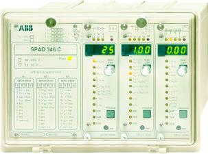
SPAD 346 C Stabilized differential relay
|
|
|
- Eileen Nichols
- 6 years ago
- Views:
Transcription


1 SPAD 346 C Stabilized differential relay
2 Stabilized Differential Relay Type SPAD 346 C Features Integrated three-phase differential relay, three-phase overcurrent relay and multiconfigurable earth-fault relay Stabilized differential relay module providing winding short-circuit and interturn fault protection for two-winding power-transformers and generator-transformer units, and interwinding short-circuit protection for generators. Earth-fault relay module providing protection for the transformer HV and LV side according to the selected principle: stabilized differential current principle, high-impedance principle, residual current principle or neutral current principle Three-stage overcurrent module providing protection for power transformers and generators and two-stage back-up earth-fault protection Short operate time even at partial saturation of the current transformers Operation characteristic of differential relay module easily adapted for different applications Stabilized against unwanted operations at faults occurring outside the protected area and at transformer inrush Second harmonic restraint for prevention of unwanted relay operations at transformer inrush Fifth harmonic restraint for prevention of unwanted relay operations at transformer overexcitation - The fifth harmonic restraint can be aborted if the ratio of the fifth harmonic and the basic frequency component rises too high at dangerous overvoltages Wide CT ratio correction range - accurate correction through digital setting o interposing current transformers needed for the protection of two-winding power transformers - numerical vector group matching on HV and LV side Four heavy-duty output relays for circuit breaker tripping and five output relays for signalling Five programmable external control inputs intended for alarm and trip signals from gas relays, oil temperature sensors and other sensors of transformer auxiliary devices Integrated circuit breaker failure protection with adjustable operate time Differential relay and earth-fault relay modules provided with integrated disturbance recorder functions for analog and digital signals - signals to be used for triggering selectable Sensitive phase current and phase angle displays facilitate checking of energizing circuit connections and vector group matchings High immunity to electrical and electromagnetic interference allows the relay to be used in severe environments High availability and system reliability due to continuous supervision of hardware and software Powerful software supports relay parametrization and reading of measured, recorded and event data CE marking according to the EC directive for EMC.
3 Application The stabilized differential relay SPAD 346 C is designed for protecting two-winding power transformers and generator-transformer units against winding short-circuit, interturn fault, earth fault and short circuit, and generators and motors against interwinding short-circuit and pole short circuit. In addition, the relay can be used for the protection of three-winding power transformers, provided 75% of the short circuit power to the power transformer is supplied from the same direction, and for the protection of compensating chokes and short cable lines. o interposing transformers are needed for the protection of two-winding power transformers, as the relay allows the vector group matching, the elimination of the zerosequence component of the phase currents and the CT ratio corrections to be carried out numerically. Earth faults outside the protected area can cause differential currents if the star point of the power transformer to be protected is earthed on the HV side or the LV side. ormally, unwanted relay operations can be avoided by eliminating the zero-sequence components of the phase currents in the vector group matching. Should the LV side of a YDconnected transformer with earthed star point be earthed via a zig-zag connected earthing transformer, the zero-sequence components can be numerically eliminated in the relay. At single-phase or two-phase earth faults within the protected area the sensitivity of the normal, phase current measuring differential protection will not be sufficient, in particular, if the star point of the transformer is earthed via a resistor. The earth-fault relay module provides coverage for these situations as well. The combined overcurrent and earth-fault relay module provides phase overcurrent protection and back-up earth-fault protection for the protected object. The current transformer connections and the vector group matching are easily checked by means of a low-voltage test and the sensitive phase current and phase angle displays of the relay. The test includes the current transformers on both the HV side and the LV side of the power transformer. The disturbance recording functions integrated into the differential relay module and the earth-fault relay module can be started, for example, by an external control signal or the operate signals of the module. The disturbance record provides vital information about current magnitudes, curve forms and digital relay module signals, for instance, after a fault situation. The differential relay is provided with push-buttons and displays for local manmachine communication and a serial interface for remote communication with higher-level systems. The relay is a member of the SPACOM substation equipment system, which is part of ABB s Distribution Automation system and ABB s Panorama concept.
4 Relay module features Differential relay module SPCD 3D A I 1 I d I 2 L1 L2 L3 P I n [%] S [%] I 2tp I n I d I n >> I 1 I n I 2 I n SGF SGB SGR 3 I > IRF RESET STEP I d2f I d1f > [%] I d5f I d1f > [%] I d5f I d1f >> [%] PROGRAM SPCD 3D53 Three-phase stabilized differential relay module for protecting twowinding power transformers and generator-transformers units against interwinding short circuit and interturn faults, and power-generators against winding short circuit and pole short circuit. The operation of the module is based on measuring the fundamental frequency component of the phase currents; the DC components and the harmonics of the phase currents are digitally filtered umerical setting of the power transformer vector group The zero-sequence component of the phase currents can be separately eliminated from the phase currents umerical setting of the correction of the CT ratio The operation characteristic of the stabilized differential current stage matchable to the requirements of the application Adjustable start current value of the instantaneous differential current stage Adjustable second and fifth harmonic restraint Software matrix for linking the trip, blocking and control signals to desired output relays Local and remote numerical presentation of phase current amplitudes and phase differences Integrated circuit-breaker failure protection with adjustable operate time Integrated disturbance recorder for phase currents and digital relay signals Local man-machine communication via push-buttons and display Continuous self-supervision of electronic circuits and program execution Earth-fault relay module SPCD 2D55 I 01 > I 02 > ΣI 1 ΣI 2 I 01 I d1 I d2 I 02 IRF P 1 I n [%] t 01 > [ s] P 2 I n [%] t 02 > [ s] I 01 I n I 01 Σ I 1 [%] I1 In I 02 I n I 02 Σ I 2 [%] I2 In SGF SGB RESET STEP I2f I1f ( I 01) > [%] I2f I1f ( I 02) > [%] PROGRAM Provides winding earth-fault protection for two-winding power transformers Four earth-fault protection principles available: high-impedance, numerical stabilized differential current, residual overcurrent, or neutral overcurrent principle Basic setting and operate time to be separately adjusted for the HV side and the LV side Adjustable second harmonic restraint Software matrix for linking the start, trip, blocking and control signals to the desired output relays Integrated circuit-breaker failure protection with adjustable operate time Integrated disturbance recorder for phase currents, neutral currents and digital relay signals Local man-machine communication via push-buttons and display Continuous self-supervision of electronic circuits and program execution SGR 0029A SPCD 2D55
5 Combined overcurrent and earth-fault relay module SPCJ 4D28 I L1 I L2 I L3 I o IRF I > I n t > [ s] k I >> I n t >> [ s] I > >>I n t > >> [ s] I 0 > SGF SGB I n 3 I > I RESET STEP t 0 > [ s ] k 0 I 0 >> I n t 0 >> [ s ] I > [%] t > [ s] PROGRAM Three three-phase overcurrent stages for protecting power transformers, generators and generator-transformer units against short circuit Low-set overcurrent stage with definite time or inverse time characteristic, high-set and superhigh-set overcurrent stage with definite time characteristic Two non-directional earth-fault stages for back-up protection of the power transformers and the generator-transformer unit Low-set earth-fault stage with definite time or inverse time characteristic, high-set stage with definite time characteristic Sensitive phase unbalance unit providing protection against phase discontinuity, single-phasing and generator unbalance Software matrix for linking the start and trip signals to the desired output relays Integrated circuit-breaker failure protection with adjustable operate time Local man-machine communication via push-buttons and display Continuous self-supervision of electronic circuits and program execution SGR 0023A SPCJ 4D28
6 Block and connection diagram L1 P2 P1 P1 P2 L2 L3 S2 S1 S1 S2 S1 P1 P1 S1 Rx Tx S2 P2 P2 S2 SPA-ZC_ (~) - (~) U aux X01 X02 X03 X04 X05 X06 X07 X08 X09 X025 X026 X027 X037 X038 X039 X013 X014 X015 X016 X017 X018 X019 X020 X021 U5 X21 X22 - I O SERIAL PORT U6 IRF X216 X217 X218 IRF X11 X12 X13 X14 X15 X16 X17 X18 X19 X110 SPAD 346 C U4 BS1 BS2 BS3 BS4 BS5 Y Y BS1 BS2 BS3 BS4 BS5 BS1 BS2 BS3 BS4 BS5 BS1 BS2 BS3 U1 3 I> 3 I>> U2 I 01> I 02> U3 3I> I I> IRF SS1 SS2 SS3 SS4 TS1 TS2 TS3 TS4 I O IRF SS1 SS2 SS3 SS4 TS1 TS2 TS3 TS4 I O IRF SS1 SS2 SS3 SS4 TS1 TS2 TS3 TS4 I O SS1 SS2 SS3 SS4 TS1 TS2 TS3 TS4 X214 X215 X211 X212 X213 X29 X210 X27 X28 X25 X26 X23 X24 X115 X116 X117 X118 X111 X112 X113 X114 Fig. 1. Block and connection diagram for the stabilized differential relay SPAD 346 C
7 Technical data Energizing inputs Rated current I n Terminal numbers X01-3, X01-2, 4-6, , 7-8 X013-15, X013-14, X019-21, X019-20, X X Thermal current withstand continuously 4 A 20 A for 10 s A for 1 s 100 A 500 A Dynamic current withstand half-wave value 250 A 1250 A Input impedance <100 mω <20 mω Rated frequency f n acc. to order Output relays Trip relays Terminal numbers 50 Hz or 60 Hz X X X23-4, V acdc Rated voltage Continuous current carrying capacity Make and carry for 0.5 s 30 A Make and carry for 3 s 1 Breaking capacity for dc when the control circuit time constant LR at the control voltage levels V dc 3 A Contact material AgCdO 2 Signal relays Terminal numbers X2 7-8, 9-10, X214-15, Rated voltage 250 V acdc Continuous current carrying capacity Make and carry for 0.5 s 10 A Make and carry for 3 s 8 A Breaking capacity for dc when the signal circuit time constant LR at the signalling voltage levels V dc Contact material AgCdO 2 Control inputs Terminal numbers X11-2, 3-4, 5-6, 7-8, 9-10 Control voltage operative range V dc or V ac Current drain of activated control input ma Active state of input input active when energized input active when non-energized Auxiliary power supply Terminal numbers X21-2 Supply module type SPGU 240A1: rated voltages U n = V ac U n = V dc operative range U = V acdc Module type SPGU 48B2 rated voltages U n = V ac operative range U = V dc Power consumption under quiescentoperation conditions 12 W18 W Data communication Transmission mode Fibre-optic serial bus Coding ASCII Data transfer rate, selectable 4800 Bd or 9600 Bd Electricaloptical bus connection module powered from the host relay for plastic core cables SPA-ZC 21BB for glass fibre cables SPA-ZC 21 MM Electricaloptical bus connection module powered from the host relay andor an externalpower source for plastic core cables SPA-ZC 17BB for glass fibre cables SPA-ZC 17 MM Software support Substation monitoring program SMS 010 Evaluation program for disturbance records DR-COM
8 Test voltages Dielectric test voltage (IEC 255-5) Impulse test voltage (IEC 255-5) Insulation resistance (IEC 255-5) 2.0 kv, 50 Hz, 1 min 5 kv, µs, 0.5 J >100 MΩ, 500 V dc Disturbance tests High-frequency disturbance test (IEC , class III) common mode 2.5 kv, 1 MHz, differential mode 1.0 kv, 1 MHz, Electrostatic discharge ( IEC and IEC 801-2, class III) air discharge 8 kv contact discharge 6 kv Fast transients (IEC , class III) and IEC 801-4, level IV power supply inputs 4 kv other inputs 2 kv Environmental conditions Service temperature range Transport and storage temperature range (IEC ) Temperature influence Relative humidity (IEC ) C C 0.1% C Degree of protection by enclosure of flush mounting relay case (IEC 529) IP 54 Weight of fully equipped relay 93 95%, 55 C, 6 cycles 6 kg RELAY MODULE DATA Stabilized differential relay module SPCD 3D53 Selectable rated frequency f n Hz CT ratio correction range on power transformer HV side I 1 I n CT ratio correction range on power transformer LV side I 2 I n Stabilized differential current stage 3 I> Basic start ratio PI n % Starting ratio setting S % Second turning point I 2tp I n of characteristic curve Harmonics blocking ratio I d2f I d1f > % Harmonics blocking ratio I d5f I d1f > % Harmonics deblocking ratio I d5f I d1f >> % Operate time (including heavy duty output relays) at currents x operate value <50 ms at currents above 4 x operate value <45 ms ±4% of set value or ±2% x I n Instantaneous differential current stage 3 I>> Start ratio I d I n >> Operate time (including heavy-duty output relays) at ratios in the range x I d I n >> <35 mm at ratios above 2.6 x I d I n >> <30 ms ±4% of set value of 2% x I n Circuit breaker failure protection Operate time s Integrated disturbance recorder Recording length 38 cycles Recording memory capacity 1 recording = 38 cycles Sampling frequency 40 samplescycle Signals to be recorded 6 analog signals 11 digital signals Triggering when the selected digital signal is activated when the selected digital signal resets Length of recording preceding triggering cycles
9 Earth-fault relay module SPCD 2D55 Selectable rated frequency f n Hz Stabilized differential relay principle Basic start ratio on HV side P 1 I n % Operate time on HV side t 01 > s Basic start ratio on LV side P 2 I n % Operate time setting on LV side t 02 > s Correction range of HV side neutral connection CT ratio I 01 I n Setting of minimum ratio of HV side neutral current and residual current of phase currents I 01 I % Correction range of LV side neutral connection CT ratio I 02 I n Setting of minimum ratio of LV side neutral current and residual current of phase currents I 02 I % Second harmonics restraint ratio I 2f I 1f of HV side neutral current I % Second harmonics restraint ratio I 2f I 1f of LV side neutral current I % Correction range of HV side phase CT ratio I 1 I n Correction range of LV side phase CT ratio I 2 I n Operate time at minimum delay (including heavyduty output relays) ±4% of set value or ±2% x I n Principle based on calculated residual current Basic start ratio P 1 I n on HV side % Operate time t 01 > on HV side s Basic start ratio P 2 I n on LV side % Operate time t 02 > on LV side s Correction range of HV side phase CT ratio I 1 I n Correction range of LV side phase CT ratio I 2 I n Operate time at minimum delay (including heavyduty output relays) ±4% of set value or ±2% x I n Principle based on measured residual current or neutral current Basic start ratio P 1 I n on HV side % Operate time t 01 > on HV side s Basic start ratio P 2 I n on LV side % Operate time t 02 > on LV side s Correction range of HV side neutral connection CT ratio I 01 I n Correction range of LV side neutral connection CT ratio I 02 I n Second harmonics restraint ratio I 2f I 1f of HV side neutral current I % Second harmonics restraint ratio I 2f I 1f of LV side neutral current I % Operate time at minimum delay (including heavyduty output relays) ±4% of set value or ±2% x I n Restricted earth-fault principle (high-impedance type earth-fault protection) Basic start ratio P 1 I n on HV side % Operate time t 01 > on HV side s Basic start ratio P 2 I n on LV side % Operate time t 02 > setting on LV side s Correction range of HV side neutral connection CT ratio I 01 I n Correction range of LV side neutral connection CT ratio I 02 I n Operate time at minimum delay (including heavyduty output relays) Circuit-breaker failure protection Operate time ±4% of set value or ±2% x I n s Integrated disturbance recorder Recording length 30 cycles Recording memory capacity 1 recording = 30 cycles Sampling frequency 40 samplescycle Signals to be recorded 8 analog signals 12 digital signals Triggering when the selected digital signal is activated - when the selected digital signal resets Length of recording preceding triggering cycles
10 Overcurrent and earth-fault relay module SPCJ 4D28 Low-set overcurrent stage I> Start current I> definite time characteristic x I n inverse time characteristic x I n * Start time, typ. 70 ms Operation characteristic definite time characteristic operate time s inverse time characteristic acc. to BS 142 and IEC special characteristic acc. to ABB practice Extremely inverse Very inverse ormal inverse Long-time inverse RI-type inverse RXIDG-type inverse time multiplier k Reset time, typ. Retardation time <30 ms Drop-offpick-up ratio, typ Operate time accuracy at definite time operation characteristic Operate time accuracy class E at inverse time ±2% of set time or ±25 ms characteristic 5 ±3% of set current High-set overcurrent stage I>> Start current I>> x I n or, infinite Start time, typ. Operate time s Reset time, typ. Retardation time <30 ms Drop-offpick-up ratio, typ Operate time accuracy ±2% of set time or ±25 ms ±3% of set current Superhigh-set overcurrent stage I>>> Start current I>>> x I n or, infinite Start time, typ. Operate time s Reset time, typ. Retardation time <30 ms Drop-offpick-up ratio, typ Operate time accuracy ±2% of set time or ±25 ms ±3% of set current Low-set residual earth-fault stage I 0 > Start current I 0 > x I n Start time, typ. 70 ms Operation characteristic definite time characteristic operate time s inverse time characteristic acc. to BS 142 and IEC special characteristic acc. to ABB practice Extremely inverse Very inverse ormal inverse Long-time inverse RI-type inverse RXIDG-type inverse time multiplier k Reset time, typ. Retardation time <30 ms Drop-offpick-up ratio, typ Operate time accuracy at definite time operation characteristic Operate time accuracy class E at inverse time ±2% of set time or ±25 ms characteristic 5 ±3% of set current High-set residual earth-fault stage I 0 >> Start current I 0 >> x I n or, infinite Start time, typ. 50 ms Operate time s Reset time, typ. Drop-offpick-up ratio, typ Operate time accuracy ±2% of set time or ±25 ms ±3% of set current Phase discontinuity protection stage I> Start current I> % x I n or, infinite Start time, typ. 150 ms Operate time s Reset time, typ. 80 ms Drop-offpick-up ratio, typ Operate time accuracy ±2% of set value or ±25 ms ±1 unit ±3% of set current * At inverse time characteristic the effective setting range is x I n, although setting values greater than 2.5 x I n can be set on the relay.
11 Mounting and Dimensions Flush mounting relay case (dimensions in millimetres) ± ±1 Panel cut-out Semi-flush mounting a b Raising frame SPA-ZX 301 SPA-ZX 302 SPA-ZX 303 a b Mounting in 19 inch cabinets and frames An ancillary mounting plate, height 4U (~177 mm), is recommended to be used when the protection relays are to be mounted in 19 inch frames or cabinets. The ancillary mounting plate type SPA-ZX 304 accommodates two size 300 relays and type SPA-ZX 305 one size 300 relay. Projecting mounting When projecting mounting is preferred a relay case type SPA-ZX 318 is used. The relay case for projecting mounting is provided with front connectors. 0,4 482,6 0 (19") ø6 21,5 101,6 7 0, (4U) SPA-ZX 304 0,4 482,6 0 (19") 21,5 101,6 7 0, (4U) SPA-ZX 305
12 Copyright 2010 ABB. All rights reserved 1MRS MDS F ABB Oy, Distribution Automation P.O.Box 699 FI VAASA Finland Tel: Fax: ABB Limited, Distribution Automation Maneja, Vadodara , India Tel: Fax:
Stabilized Differential Relay SPAD 346. Product Guide
 Issued: July 1998 Status: Updated Version: D/21.03.2006 Data subject to change without notice Features Integrated three-phase differential relay, three-phase overcurrent relay and multiconfigurable earth-fault
SPAD 346 C. Stabilized Differential Relay. User s manual and Technical description SPAD 346 C V ~ V. f n SPCD 3D53 SPCJ 4D28
 SPAD 6 C Stabilized Differential Relay User s manual and Technical description f n = 50Hz 60Hz I n = A 5A ( I ) I n = A 5A ( I ) I n = A 5A ( I 0 ) I n = A 5A ( I 0 ) 5 I I d L L I L I > IRF I 0 > I 0
Fault indicator. Application. SPEF 3A2 C 1MRS MBG Issued: April 1999 Status: Updated Version: B/ Data subject to change without notice
 Issued: April 1999 Status: Updated Version: B/08.11.200 Data subject to change without notice Features Versatile, multifunction line fault indicator for distribution networks Overcurrent, earth-fault and
High-set undervoltage stage with definitetime. or inverse definite minimum time (IDMT) characteristic. Low-set undervoltage stage with definitetime
 characteristic. Low-set undervoltage stage with definitetime") Issued: 5.06.999 Status: 5.06.999 Version: B/09..00 Data subject to change without notice Features Overvoltage and undervoltage protection Single- or three-phase operation High-set overvoltage stage with
Issued: 5.06.999 Status: 5.06.999 Version: B/09..00 Data subject to change without notice Features Overvoltage and undervoltage protection Single- or three-phase operation High-set overvoltage stage with
SPAE 010, 011 High Impedance Protection Relay
 SPAE 010, 011 High Impedance Protection Relay User s manual and Technical description f n = 50/60 Hz U n = 50 / 100 / 200 V 2 5 U REF > SPAE 010 0.8 U aux 0.6 1.0 RESET OK x 80... 265 V ~ _ 0.4 U > U n
SPAJ 144 C. Combined overcurrent and earth-fault relay SPAJ 144 C. User s manual and Technical description A CBFP V ~ V.
 SPAJ C Combined overcurrent and earth-fault relay User s manual and Technical description f n = 0Hz 60Hz I n = A I n = A A A ( I ) ( I o) I > I I L I L I L I 0 IRF SPAJ C REGISTERS SPCJ D8 0 0 0 0 0 6
SPAA 341 C. Feeder Protection Relay. User s manual and Technical description SPAA 341 C. U aux V ~ V. f n. t 2 > [ s ] 0 I 0 >> Trip
![SPAA 341 C. Feeder Protection Relay. User s manual and Technical description SPAA 341 C. U aux V ~ V. f n. t 2 > [ s ] 0 I 0 >> Trip](/thumbs/72/67603349.jpg "SPAA 341 C. Feeder Protection Relay. User s manual and Technical description SPAA 341 C. U aux V ~ V. f n. t 2 > [ s ] 0 I 0 >> Trip") SPAA C Feeder Protection Relay User s manual and Technical description f n = 0Hz 0Hz I n = A A ( I ) I n = A A ( I 0B ) I n = 0,A A ( I 0 ) U n = 00V 0V 0V ( ) U 0 I > I I L I L I L I o IRF Uo I o ϕ U
SPAA C Feeder Protection Relay User s manual and Technical description f n = 0Hz 0Hz I n = A A ( I ) I n = A A ( I 0B ) I n = 0,A A ( I 0 ) U n = 00V 0V 0V ( ) U 0 I > I I L I L I L I o IRF Uo I o ϕ U
SPAS 348 C. Feeder Protection Relay. User s manual and Technical description SPAS 348 C V ~ V. t 2 > [ s ] f n = 50Hz 60Hz
![SPAS 348 C. Feeder Protection Relay. User s manual and Technical description SPAS 348 C V ~ V. t 2 > [ s ] f n = 50Hz 60Hz](/thumbs/82/85869345.jpg "SPAS 348 C. Feeder Protection Relay. User s manual and Technical description SPAS 348 C V ~ V. t 2 > [ s ] f n = 50Hz 60Hz") SPAS 8 C Feeder Protection Relay User s manual and Technical description f n = 50Hz 60Hz I n = A 5A ( I ) I n = 0,A A ( I 0 ) U n 00V...0V ( U ) U n = 00V/0V/0V ( U 0 ) 5 I > I L U I L U IRF B I > I L
SPAS 8 C Feeder Protection Relay User s manual and Technical description f n = 50Hz 60Hz I n = A 5A ( I ) I n = 0,A A ( I 0 ) U n 00V...0V ( U ) U n = 00V/0V/0V ( U 0 ) 5 I > I L U I L U IRF B I > I L
SPAA 120 C and SPAA 121 C Feeder protection relay
 SPAA 10 C and SPAA 11 C Feeder protection relay User s manual and Technical description f n = 50Hz 60Hz I n = 1A 5A ( I ) I n = 1A 5A ( I o ) U n = 100V 110V ( U o ) 5 B I > I I L1 I L3 Uo I o IRF SPAA
SPAJ 110 C. Earth-fault relay SPAJ 110 C. User s manual and Technical description. U aux V ~ V f n. n ( I o>> SPCJ 1C8
 SPAJ 110 C Earth-fault relay User s manual and Technical description I n = 1A 5A ( I ) f n = 50Hz 60Hz 2 5 B I o I IRF SPAJ 110 C 80...265V ~ 18...80V U aux STEP I o > I n 0.1 0.35 0.8 STEP SPCJ 1C8 REGISTERS
Relion 605 series Self-Powered Feeder Protection REJ603 Product Guide
 Relion 605 series Relion 605 series Self-Powered Feeder Protection Product Guide Contents 1 Description...3 2 Protection functions...3 3 Application...4 4 Self-supervision...4 5 Inputs and outputs...4
REK 510 Current injection device for earth-fault protection of a synchronous machine rotor. User s Manual
 REK 50 protection of a synchronous machine User s Manual REK 50 X 0 9 8 7 6 5 4 0 V 00 V 0 V 5 6 7 Ordering No: REK 50-AA Uau = 00/0 Vac Un = 48 V Serial No: fn = 50/60 Hz Uec = ma 600 Vdc MRS 75587-MUM
SPAJ 135 C. Combined overcurrent and earth-fault relay SPAJ 135 C. User s manual and Technical description. U aux V ~ V.
 SPAJ 135 C Combined overcurrent and earth-fault relay User s manual and Technical description I n = 1A 5A ( I ) I n = 1A 5A ( I o ) f n = 50Hz 60Hz 2 5 B I L1 I L3 I o 2 I > I IRF SPAJ 135 C 80...265V
SPAJ 111 C. Sensitive earth-fault relay SPAJ 111 C. User s manual and Technical description. U aux V ~ V. f n. n ( I o>> SPCJ 1C7
 SPAJ 111 C Sensitive earth-fault relay User s manual and Technical description I n = 1A 5A ( I ) f n = 50Hz 60Hz 2 5 B I o I IRF SPAJ 111 C 80...265V ~ 18...80V U aux STEP I o > [%] I n 1.0 6.0 10 STEP
SPAC 335 C and SPAC 336 C Feeder terminals
 SPAC 335 C and SPAC 336 C Feeder terminals User s manual and Technical description I n = / 5 A( I ) I n = / 5 A( I o ) f n = 50 60 Hz SPAC 335 C U n = 00 / 0 V( U o ) 5 IRF O I B I > I I L I L3 Uo I o
Phase and neutral overcurrent protection
 Phase and neutral overcurrent protection Page 1 ssued June 1999 Changed since July 1998 Data subject to change without notice (SE970165) Features Two-phase or three-phase time-overcurrent and earth fault
SPAF 340 C Frequency Relay
 SPAF 0 C Frequency Relay User s manual and Technical description U n = 00V/0V/5V/0V 5 U f f < > < > df dt IRF SPAF 0 C 80...65 V ~ 8...80 V U aux OPERATION INDICATORS U U U SPCF D5 0 Stage Start Stage
Transformer differential protection
 Transformer differential protection Page 1 Issued June 1999 Changed since July 1998 Data subject to change without notice (SE970883) Features Three phase differential protection with two, three, five or
SPAJ 160 C. Capacitor protection relay SPAJ 160 C. User s manual and Technical description V ~ V 3I > 3I < f n 2 > TRIP.
 SPAJ 60 C Capacitor protection relay User s manual and Technical description I n = A 5A ( I ) I n = A 5A ( I ) f n = 50Hz 60Hz 5 3I > I 3I < I L I L I L3 I c IRF SPAJ 60 C 80...65V ~ 8...80V SPCJ 4D40
Harmonic restraint earth fault or single-phase overcurrent protection
 Harmonic restraint earth fault or single-phase overcurrent protection Page 1 Issued June 1999 Changed since July 1998 Data subject to change without notice (SE970885) Features Sensitive earth fault protection
SPAC 320 C. Motor protection terminal. User s manual and Technical description SPAC 320 C. U aux V _ V _ I >> / I.
 SPAC 30 C Motor protection terminal User s manual and Technical description f n = 50 60 Hz I n = / 5 A ( I ) I n = / 5 A( I o) SPAC 30 C 5 IRF O I 3I >> 3 I I L I L I L3 I o IRF TEST INTERLOCK GAS PRESSURE
SPAS 120 C Directional earth-fault relay
 SPAS 120 C Directional earth-fault relay User s manual and Technical description B I 2 f n = 0Hz 60Hz I n = 1A A ( I o ) U n = 100V 110V ( U o ) U o I o I ϕ IRF SPAS 120 C 80...26V ~ 18...80V U aux I ϕ
Differential Protection with REF 542plus Feeder Terminal
 Differential Protection with REF 542plus Application and Setting Guide kansikuva_bw 1MRS 756281 Issued: 09.01.2007 Version: A Differential Protection with REF 542plus Application and Setting Guide Contents:
Transformer protection IED RET 670
 Gunnar Stranne Transformer protection IED RET 670 Santiago Septiembre 5, 2006 1 Transformer protection IED RET670 2 Introduction features and applications Differential protection functions Restricted Earth
PD300. Transformer, generator and motor protection Data sheet
 PD300 Transformer, generator and motor protection Data sheet DSE_PD300_eng_AO No part of this publication may be reproduced by whatever means without the prior written permission of Ingeteam T&D. One of
XD1-T Transformer differential protection relay. Manual XD1-T (Revision A)
") XD1-T Transformer differential protection relay Manual XD1-T (Revision A) Woodward Manual XD1-T GB Woodward Governor Company reserves the right to update any portion of this publication at any time. Information
XD1-T Transformer differential protection relay Manual XD1-T (Revision A) Woodward Manual XD1-T GB Woodward Governor Company reserves the right to update any portion of this publication at any time. Information
REF 610 Feeder Protection Relay. Technical Reference Manual
 REF 610 1MRS 755310 Issued: 05.10.2004 Version: A/05.10.2004 REF 610 Contents 1. Introduction...6 1.1. About this manual...6 1.2. The use of the relay...6 1.3. Features...6 1.4. Guarantee...8 2. Safety
XR1 Rotor Earth Fault Relay. Manual XR1 (Revision C)
") XR1 Rotor Earth Fault Relay Manual XR1 (Revision C) Woodward Manual XR1 (EN) Woodward Governor Company reserves the right to update any portion of this publication at any time. Information provided by
XR1 Rotor Earth Fault Relay Manual XR1 (Revision C) Woodward Manual XR1 (EN) Woodward Governor Company reserves the right to update any portion of this publication at any time. Information provided by
Instantaneous Overcurrent Relay
 Midos Type MCRI Instantaneous Overcurrent Relay Features High speed operation Not slowed by dc transients Settings readily adjustable on relay front plate Two phase and earth fault relay Figure 1: Type
Overcurrent Protection / 7SJ45
 Overcurrent Protection / SJ SIPROTEC easy SJ numerical overcurrent protection relay powered by CTs Fig. / Description SIPROTEC easy SJ numerical overcurrent protection relay powered by current transformers
IRI1-ER - Stabilized Earth Fault Current Relay
 IRI1-ER - Stabilized Earth Fault Current Relay TB IRI1-ER 02.97 E 1 Contents 1. Summary 2. Applications 3. Characteristics and features 4. Design 4.1 Connections 4.1.1 Analog inputs 4.1.2 Output relays
XD1-T - Transformer differential protection relay
 XD1-T - Transformer differential protection relay Contents 1. Application and features 2. Design 3. Characteristics 3.1 Operating principle of the differential protection 3.2 Balancing of phases and current
N. TEST TEST DESCRIPTION
 Multi function system for testing substation equipment such as: current, voltage and power transformers, all type of protection relays, energy meters and transducers Primary injection testing capabilities
XR1 Rotor Earth Fault Relay. (May 2007) Manual XR1 (Revision New)
 Manual XR1 (Revision New)") XR1 Rotor Earth Fault Relay (May 2007) Manual XR1 (Revision New) Woodward Manual XR1 GB Woodward Governor Company reserves the right to update any portion of this publication at any time. Information provided
XR1 Rotor Earth Fault Relay (May 2007) Manual XR1 (Revision New) Woodward Manual XR1 GB Woodward Governor Company reserves the right to update any portion of this publication at any time. Information provided
Transformer and generator time-overexcitation relay and protection assemblies RXLK 2H and RALK
 Transformer and generator time-overexcitation relay and protection assemblies RXLK 2H and RALK (RXLK_2H.tif) RALK.psd Features Micro-processor based time-overexcitation relay with continuous settings for
T/3000 T/3000. Substation Maintenance and Commissioning Test Equipment
 T/3000 Substation Maintenance and Commissioning Test Equipment MULTI FUNCTION SYSTEM FOR TESTING SUBSTATION EQUIPMENT SUCH AS: CURRENT, VOLTAGE AND POWER TRANSFORMERS, ALL TYPE OF PROTECTION RELAYS, ENERGY
presentation contents application advantages
 presentation contents page presentation protection functional and connection schemes other connection schemes connection characteristics 9 installation 0 commissioning ordering information Sepam 00 is
)HDWXUHV Voltage restraint overcurrent stage with five different inverse or definite time characteristics
HDWXUHV Voltage restraint overcurrent stage with five different inverse or definite time characteristics") 9ROWDJHUHVWUDLQWRYHUFXUUHQW UHOD\DQGSURWHFWLRQ DVVHPEOLHV 5;,6.+DQG 5$,6. 509 033-BEN Page 1 Issued: September 2001 Changed since: June 1999 Data subject to change without notice (SE970171) (SE970896)
9ROWDJHUHVWUDLQWRYHUFXUUHQW UHOD\DQGSURWHFWLRQ DVVHPEOLHV 5;,6.+DQG 5$,6. 509 033-BEN Page 1 Issued: September 2001 Changed since: June 1999 Data subject to change without notice (SE970171) (SE970896)
Directional or Non-Directional Earth-Fault Relay REJ 527. Technical Reference Manual
 Directional or Non-Directional REJ 527 Technical Reference Manual 1MRS750616-MUM Issued: 07.07.1999 Version: C/14.11.2005 Directional or Non-Directional Technical Reference Manual Contents REJ 527 1.
High-Tech Range. IRI1-ER- Stablized Earth Fault Current Relay. C&S Protection & Control Ltd.
 High-Tech Range IRI1-ER- Stablized Earth Fault Current Relay C&S Protection & Control Ltd. Contents 1. Summary 7. Housing 2. Applications 3. Characteristics and features 4. Design 7.1 Individual housing
Thermistor motor protection relays
 Thermistor motor protection relays Content Benefits and advantages... / 68 Selection table... / 68 Ordering details CM-MSE... / 69 CM-MSS... / 69 CM-MSN... / 7 PTC sensor C0... / 7 Technical data... /
Time-overcurrent relays and protection assemblies
 Time-overcurrent relays and protection Page 1 509 002-BEN Issued January 2004 Revision: A Data subject to change without notice (SE970134) (SE970150) Features RXIDK 2H relay and Single-, two-, three-phase
Plug-in microprocessor controlled multifuncional relay with automatic shorting of c.t.
 Multifunctional relay Page 1 Issued: July 1998 Changed: since April 1989 Data subject to change without notice Features Plug-in microprocessor controlled multifuncional relay with automatic shorting of
IRI1-ER - Stabilized Earth Fault Current Relay. Manual IRI1-ER (Revision A)
") IRI1-ER - Stabilized Earth Fault Current Relay Manual IRI1-ER (Revision A) Woodward Manual IRI-ER GB Woodward Governor Company reserves the right to update any portion of this publication at any time.
IRI1-ER - Stabilized Earth Fault Current Relay Manual IRI1-ER (Revision A) Woodward Manual IRI-ER GB Woodward Governor Company reserves the right to update any portion of this publication at any time.
SIPROTEC easy 7SJ46 Numerical Overcurrent Protection Relay
 Overcurrent Protection / 7SJ46 SIPROTEC easy 7SJ46 Numerical Overcurrent Protection Relay Function overview Fig. /11 Description The SIPROTEC easy 7SJ46 is a numerical overcurrent protection relay which
N. TEST TEST DESCRIPTION
 Multi function system for testing substation equipment such as: current, voltage and power transformers, over-current protection relays, energy meters and transducers Primary injection testing capabilities
TD 1000 PLUS. Secondary Injection Relay Test Set. Designed for testing relays and transducers
 Secondary Injection Relay Test Set Designed for testing relays and transducers Two current outputs to test differential relays Convertible current and voltage generator With phase angle shifter Frequency
Type CP-S, CP-C & CP-A Switch mode
 Switch mode power CP-S, CP-C & CP-A Switch mode Characteristics CP-S and CP-C range Output current 5 A, 10 A and 20 A Integrated power reserve of up to 50 % 5 A and 10 A devices with pluggable connecting
Multimeter 500CVD21 RTU500 series
 Remote Terminal Units - Data sheet Multimeter 500CVD21 RTU500 series CT/VT interface with 4 voltage and 24 current inputs for direct monitoring of 3/4 wire 0 300 V AC (line to earth), 0...500 V AC (phase
T 1000 PLUS. Secondary Injection Relay Test Set. Designed for testing relays and transducers
 Secondary Injection Relay Test Set Designed for testing relays and transducers Microprocessor controlled With phase angle shifter Frequency generator Test results and settings are saved into local memory
Low Voltage Products. Enclosed Third Harmonic Filter THF and THF star Enclosed units. Brochure THFS1GB 03_04 1SCC330003C0201
 Low Voltage Products Enclosed Third Harmonic Filter and star Enclosed units Brochure S1GB 3_4 1SCC333C21 The Third Harmonic - a Growing Problem Today's electrical networks and plants are under much more
XI1-I Time overcurrent relay. (Januar 2007) Manual XI1-I (Revision New)
 Manual XI1-I (Revision New)") XI1-I Time overcurrent relay (Januar 2007) Manual XI1-I (Revision New) Woodward Manual XI1-I GB Woodward Governor Company reserves the right to update any portion of this publication at any time. Information
XI1-I Time overcurrent relay (Januar 2007) Manual XI1-I (Revision New) Woodward Manual XI1-I GB Woodward Governor Company reserves the right to update any portion of this publication at any time. Information
User s manual and Technical description. Self-Powered Feeder Protection REJ603
 and Technical description Self-Powered Feeder Protection 2 Document ID: Issued: 18.02.2008 Revision: A Product version:1.0 Copyright 2008 ABB. All rights reserved 3 Copyright This document and parts thereof
NPRG860 & NPRG870 perform synchronization and paralleling of generators with electrical network. NPRG860 features a speed adjustment function.
 REGULATION AUTOMATIC SYNCHRONIZER for GENERATOR NPRG860 & NPRG870 perform synchronization and paralleling of generators with electrical network. NPRG860 features a speed adjustment function. NPRG870 adds
Thermistor motor protection relays
 Thermistor motor protection relays Content Benefits and advantages... / 68 Selection table... / 68 Ordering details CM-MSE... / 69 CM-MSS... / 69 CM-MSN... / 7 PTC sensor C0... / 7 Technical data... /
NPRG860 NPRG870 REGULATION. Automatic Synchronizer for Generator
 REGULATION Automatic Synchronizer for Generator NPRG860 & NPRG870 perform synchronization and paralleling of generators with electrical network. NPRG860 features a speed adjustment function. NPRG870 adds
4Q POWER AMPLIFIERS AC AND DC 3000VA 3x3000VA
 PERFORMANCES High accuracy High stability Fast transients High inrush current facilities Wide bandwidth 25 khz at -3dB Internal waveform DC and up to 10 khz Very low distortion Quadrant change without
XP2-R Power and Reverse Power Relay
 XP2-R Power and Reverse Power Relay Manual XP2-R (Revision C) Woodward Manual XP2-RE Woodward reserves the right to update any portion of this publication at any time. Information provided by Woodward
HV / MV / LV electrical network quality analyzers Class A. Communication port: local, modem, integrated Ethernet, multi-point
 2010 MAP Range HV / MV / LV electrical network quality analyzers Class A > Network quality Analyzers PRODUCT ADVANTAGES COMPLIANT with the EN 61000-4-30 standard, Class A DETECTION of the fault LOCATION
SFIBER Fibre-optic Option Card for Lon Star Coupler RER 111. Technical Reference Manual
 SFIBER Fibre-optic Option Card for Lon Star Coupler RER 111 Technical Reference Manual 1MRS 750106-MUM Issued: 21.11.1996 Version: B2/18.2.2000 Checked: M.K. Approved: T.S. Fibre-optic Option Card for
SPECIFICATION FOR OVERCURRENT RELAYS
 SPECIFICATION FOR OVERCURRENT RELAYS 1/9 1. Procedure A manufacturer willing to classify an overcurrent relay according to this specification should provide: A complete file providing a clear, unambiguous
XUA1 AC Voltage and phase balance relay. (August 1996) Manual XUA1 (Revision New)
 Manual XUA1 (Revision New)") XUA1 AC Voltage and phase balance relay (August 1996) Manual XUA1 (Revision New) Woodward Manual XUA1 GB Woodward Governor Company reserves the right to update any portion of this publication at any time.
XUA1 AC Voltage and phase balance relay (August 1996) Manual XUA1 (Revision New) Woodward Manual XUA1 GB Woodward Governor Company reserves the right to update any portion of this publication at any time.
XP2-R Power and reverse power relay. (January 2006) Manual XP2-R (Revision New)
 Manual XP2-R (Revision New)") XP2-R Power and reverse power relay (January 2006) Manual XP2-R (Revision New) Woodward Manual XP2-R GB Woodward Governor Company reserves the right to update any portion of this publication at any time.
XP2-R Power and reverse power relay (January 2006) Manual XP2-R (Revision New) Woodward Manual XP2-R GB Woodward Governor Company reserves the right to update any portion of this publication at any time.
satech SynchroStar GPS 200 Series
 satech SynchroStar GPS 200 Series KEY BENEFITS Designed with high quality oscillator OCXO the device is characterized by superior frequency stability and improved holdover performance that allows maintaining
XUA1 - AC Voltage and phase balance relay
 XUA1 - AC Voltage and phase balance relay Contents 1. Applications and features 2. Design 3. Function 3.1 Voltage supervision 3.2 Unbalanced voltage supervision 4. Operation and settings 4.1 Setting of
POWER AMPLIFIERS 4 QUADRANTS 3x500 VA to 3x1500 VA - THREE-PHASES
 PERFORMANCES High accuracy High stability Fast transients High inrush current facilities Wide bandwidth Very low distortion Quadrant change without transition Very low output impedance Low noise RS232
www. ElectricalPartManuals. com Transformer Differential Relay MD32T Transformer Differential Relay
 Transformer Differential Relay The MD3T Transformer Differential Relay is a member of Cooper Power Systems Edison line of microprocessor based protective relays. The MD3T relay offers the following functions:
Time relay RXKA 1. (xx jpg) RXKA 1
 RXKA 1") Time relay RXKA 1 (xx02000674.jpg) RXKA 1 Features For protection, control, signal and industrial applications On-delay and Off-delay functions Continuous and pulse output functions Setting range 0.1-320
Time relay RXKA 1 (xx02000674.jpg) RXKA 1 Features For protection, control, signal and industrial applications On-delay and Off-delay functions Continuous and pulse output functions Setting range 0.1-320
Fixed Series Compensation
 Fixed Series Compensation High-reliable turnkey services for fixed series compensation NR Electric Corporation The Fixed Series Compensation (FSC) solution is composed of NR's PCS-9570 FSC control and
Modular multifunction generator protection
 Modular multifunction generator Page 1 Issued June 1999 Changed since July 1998 Data subject to change without notice (SE970186) Features is a modular generator that enables selection of the desired in
MHCO MHCO-RI. General Characteristics The transducer MHCO provide a measurement of current or voltage fully isolated and safe.
 -TVI -RI -RV D.C. MEASURING CONVERTER Converter for D.C. Current and/or Voltage measurement. Direct connection to D.C. mains rating up to 4 kvcc. Fully isolated multi-voltage power suppy. Fiber optic connection
Earth fault protection for isolated neutral systems with frequency converters
 Earth fault protection for isolated neutral systems with frequency converters Page Issued June 999 Changed since July 998 Data subject to change without notice (SE97089) Features Earth fault and flash-over
Protection and control. Sepam range Sepam 100 LA Self-powering protection. Merlin Gerin Square D Telemecanique
 Protection and control Sepam range Sepam 0 LA Self-powering protection Merlin Gerin Square D Telemecanique presentation contents page presentation protection functional and connection schemes other connection
Time over/underfrequency relay with protection assemblies
 Time over/underfrequency relay with protection assemblies RXFK 2H and RAFK 509 009-BEN Page 1 Issued June 1999 Changed since July 1998 Data subject to change without notice (SE970104) (SE970108) Features
3 Pole high impedance differential relay 7VH83
 Fig 1. High impedance differential protection relay 7VH83 Features l Integral CT shorting relay. l Robust solid state design. l Inrush stabilisation through filtering. l Fast operating time. l LED indicator.
NEO TELE-TRONIX PVT. LTD. 6/7 Bijoygarh, Kolkata , Tel : ; Fax :
 NEO TELE-TRONIX PVT. LTD. 6/7 Bijoygarh, Kolkata - 700 032, Tel : 033 2477 3126; Fax : 033 2477 2403 www.ntplindia.com SPECIFICATION NTPL MAKE MICRO-CONTROLLER BASED AUTOMATIC 50KV/10A AC HIGH VOLTAGE
Transformer Fault Categories
 Transformer Fault Categories 1. Winding and terminal faults 2. Sustained or uncleared external faults 3. Abnormal operating conditions such as overload, overvoltage and overfluxing 4. Core faults 1 (1)
Modern transformer relays include a comprehensive set of protective elements to protect transformers from faults and abnormal operating conditions
 1 Transmission transformers are important links in the bulk power system. They allow transfer of power from generation centers, up to the high-voltage grid, and to bulk electric substations for distribution
Transformer Protection
 Transformer Protection Transformer Protection Outline Fuses Protection Example Overcurrent Protection Differential Relaying Current Matching Phase Shift Compensation Tap Changing Under Load Magnetizing
DEIF A/S. Insulation monitor. Type SIM-Q
 Insulation monitor 4921232C Monitoring of insulation resistance on ungrounded AC networks (IT network) Working voltage up to 69V AC, withstands up to V DC Measuring range 1...Mohm or 1...Mohm Alarm on
DRTS 66 The new generation of advanced test equipments for Relays, Energy meters, Transducers and Power quality meters
 The new generation of advanced test equipments for Relays, Energy meters, Transducers and Power quality meters Testing all relay technologies: electromechanical, solid state, numerical and IEC61850 Manual
BE1-67N GROUND DIRECTIONAL OVERCURRENT RELAY FEATURES ADDITIONAL INFORMATION. FUNCTIONS AND FEATURES Pages 2-4. APPLICATIONS Page 2
 BE1-67N GROUND DIRECTIONAL OVERCURRENT RELAY The BE1-67N Ground Directional Overcurrent Relay provides ground fault protection for transmission and distribution lines by sensing the direction and magnitude
Electronic timer CT-YDE Star-delta change-over with 1 c/o (SPDT) contact
 contact") Data sheet Electronic timer CT-YDE Star-delta change-over with c/o (SPDT) contact The CT-YDE is an electronic time relay with star-delta change-over. It is from the CT-E range. The CT-E range is the economic
Data sheet Electronic timer CT-YDE Star-delta change-over with c/o (SPDT) contact The CT-YDE is an electronic time relay with star-delta change-over. It is from the CT-E range. The CT-E range is the economic
ABB 1. Multifunctional three-phase monitoring relays. CM-MPS.11, CM-MPS-21, CM-MPS.31 and CM-MPS.41 Data sheet. Features. Approvals. Marks.
 2CDC 251 048 F0t08 CM-MPS.11 2CDC 251 049 F0t08 CM-MPS.21 2CDC 251 050 F0t08 CM-MPS.31 2CDC 251 051 F0t08 CM-MPS.41 R/T: yellow LED - relay status, timing F1: red LED - fault message F2: red LED - fault
Electronic timer CT-TGD.12 Pulse generator with 1 c/o (SPDT) contact
 contact") Data sheet Electronic timer CT-TGD.12 Pulse generator with 1 c/o (SPDT) contact The CT-TGD.12 is an electronic time relay with the function pulse generator. It is from the CT-D range. With their MDRC profile
Data sheet Electronic timer CT-TGD.12 Pulse generator with 1 c/o (SPDT) contact The CT-TGD.12 is an electronic time relay with the function pulse generator. It is from the CT-D range. With their MDRC profile
MULTI FUNCTION OVER CURRENT AND EARTH FAULT RELAY[50/51X3,50/51N]
![MULTI FUNCTION OVER CURRENT AND EARTH FAULT RELAY[50/51X3,50/51N]](/thumbs/85/92859087.jpg "MULTI FUNCTION OVER CURRENT AND EARTH FAULT RELAY[50/51X3,50/51N]") DOG-M51D Feature The multi-ocr is a microprocessor based digital type protective relay that has 3 phases overcurrent and ground overcurrent element which are provided with inverse, very inverse, extremely
DOG-M51D Feature The multi-ocr is a microprocessor based digital type protective relay that has 3 phases overcurrent and ground overcurrent element which are provided with inverse, very inverse, extremely
T 1000 PLUS Secondary Injection Relay Test Set
 Secondary Injection Relay Test Set Designed for testing relays and transducers Microprocessor controlled With phase angle shifter Frequency generator Test results and settings are saved into local memory
Catalogue 1SFC en, Edition 3 November 2003 Supersedes Catalogue 1SFC en, Edition 2 November Arc Guard System TVOC
 Catalogue 1SFC 266006-en, Edition 3 November 2003 Supersedes Catalogue 1SFC 266006-en, Edition 2 November 2000 Arc Guard System TVOC System units The two units of the are used as below: Approvals 1. with
T 1000 PLUS. Secondary Injection Relay Test Set. Designed for testing relays and transducers
 Secondary Injection Relay Test Set Designed for testing relays and transducers Microprocessor controlled With phase angle shifter Frequency generator High power outputs Large graphical display Compact
XU2-AC AC voltage relay. (Februar 1997) Manual XU2-AC (Revision New)
 Manual XU2-AC (Revision New)") XU2-AC AC voltage relay (Februar 1997) Manual XU2-AC (Revision New) Woodward Manual XU2-AC GB Woodward Governor Company reserves the right to update any portion of this publication at any time. Information
XU2-AC AC voltage relay (Februar 1997) Manual XU2-AC (Revision New) Woodward Manual XU2-AC GB Woodward Governor Company reserves the right to update any portion of this publication at any time. Information
Protection of Electrical Networks. Christophe Prévé
 Protection of Electrical Networks Christophe Prévé This Page Intentionally Left Blank Protection of Electrical Networks This Page Intentionally Left Blank Protection of Electrical Networks Christophe Prévé
Reyrolle Protection Devices. 7SG14 Duobias M Transformer Protection. Answers for energy
 Reyrolle Protection Devices 7SG4 Duobias M Transformer Protection Answers for energy 7SG4 Duobias M Transformer Protection Description Optional Functionality High Impedance Restricted Earth Fault per winding
DATASHEET - ETR4-70-A. Delivery program. Timing relay, 2W, 0.05s-100h, multi-function, VAC/DC, potentiometer connection
 DATASHEET - ETR4-70-A Delivery program Timing relay, 2W, 0.05s-100h, multi-function, 24-240VAC/DC, potentiometer connection Part no. ETR4-70-A Catalog No. 031888 Eaton Catalog No. XTTR6A100H70B EL-Nummer
PS-3000-AVAS PS-5000-AVAS DC SOURCE FOR AUTOMOTIVE TESTS
 PERFORMANCES High accuracy High stability Fast times of transition High inrush current Wide bandwidth Switching from Q1 to Q4 without transition Very low output impedance Ripple & noise superposition Dips
RAIDK, RAIDG, RAPDK and RACIK Phase overcurrent and earth-fault protection assemblies based on single phase measuring elements
 RAIDK, RAIDG, RAPDK and RACIK Phase overcurrent and earth-fault protection assemblies based on single phase measuring elements User s Guide General Most faults in power systems can be detected by applying
DATASHEET - ETR4-51-A. Delivery program. Technical data General. Timing relay, star-delta, 50 ms, 1W, 3-60s, VAC/DC
 DATASHEET - ETR4-51-A Timing relay, star-delta, 50 ms, 1W, 3-60s, 24-240VAC/DC Part no. ETR4-51-A Catalog No. 031884 Eaton Catalog No. XTTR6A60S51B EL-Nummer 0004133308 (Norway) Delivery program Product
Type: ADR233A (ADITYA V2 Series) (Preliminary) ASHIDA Numerical 3 Phase Tx. Differential Protection Relay
 (Preliminary) ASHIDA Numerical 3 Phase Tx. Differential Protection Relay") Ashida Numerical 3 Directional Phase Tx. 3O/C Differential + 1E/F Protection PROTH. ERR FAULT 87 L5 L6 REF L7 BF TRIP ADR 233B_V2 233A_V2 Protection Features: 3Phase Tx. Differential Protection + REF Programmable
Ashida Numerical 3 Directional Phase Tx. 3O/C Differential + 1E/F Protection PROTH. ERR FAULT 87 L5 L6 REF L7 BF TRIP ADR 233B_V2 233A_V2 Protection Features: 3Phase Tx. Differential Protection + REF Programmable
Protective Relays Digitrip 3000
 New Information Technical Data Effective: May 1999 Page 1 Applications Provides reliable 3-phase and ground overcurrent protection for all voltage levels. Primary feeder circuit protection Primary transformer
POWER FACTOR CORRECTION. HARMONIC FILTERING. MEDIUM AND HIGH VOLTAGE SOLUTIONS.
 POWER FACTOR CORRECTION. HARMONIC FILTERING. MEDIUM AND HIGH VOLTAGE SOLUTIONS. This document may be subject to changes. Contact ARTECHE to confirm the characteristics and availability of the products
Compact current relay and protection assemblies RXHL 401 and RAHL 401
 Compact current relay and protection assemblies RXHL 401 and RAHL 401 (xx00000120.tif) Features Three phase compact current relay for: Phase overcurrent protection, three stages Earth-fault overcurrent