90 ReStart AUTOMATIC RECLOSING DEVICES
|
|
|
- Shauna Douglas
- 5 years ago
- Views:
Transcription
: (V) 230 AC (1) 400 AC Minimum operating voltage (min Ue) (V) 85% Ue Maximum operating voltage (max Ue): (V) 110% Ue Rated insulation voltage (Ui):")
: (A) 630 Rated conditional residual short-circuit current with fuse (IΔc): (A) 10000 (gl 63A) for In=25-40A 10000 (gl 80A) for In=63A Number of poles: 2 4 Type of")
1 RESTART WITH AUTOTEST Technical data TYPE ReStart with Autotest 2P ReStart with Autotest PRO 2P ReStart with Autotest PRO 4P Electrical characteristics Standards: EN 50557, EN Distribution system: TT - TN-S Rated operational voltage (Ue): (V) 230 AC (1) 400 AC Minimum operating voltage (min Ue) (V) 85% Ue Maximum operating voltage (max Ue): (V) 110% Ue Rated insulation voltage (Ui): (V) 500 Dielectric strength test voltage between pole and earth: (V) 2500 AC for 1 minute Rated impulse withstand voltage (Uimp): (kv) 4 Overvoltage category: III Rated frequency: (Hz) 50 Residual making and breaking capacity (IΔm): (A) 630 Rated conditional residual short-circuit current with fuse (IΔc): (A) (gl 63A) for In=25-40A (gl 80A) for In=63A Number of poles: 2 4 Type of associated residual current circuit breaker: A[IR] Rated current (In): (A) Rated residual operating current (IΔn): (ma) Rated non-operating resistance between live parts and earth (Rdo): (kω) (30mA) (300mA) Rated operating resistance between live parts and earth (Rd): (kω) (30mA) - 5 (300mA) Power loss at In: (W) 2.2 (25A) (40A) (63A) 3.5 (25A) - 6 (40A) - 12 (63A) Off-load absorbed power: (VA) 4 (cosφ=0.2) Power absorbed during automatic reclosing: (VA) 41 (cosφ=0.5) Power supply: from above Mechanical characteristics Width in DIN modules: 5 7 Reclosing time: (s) 10 Autotest cycle time: (s) 7 Maximum operational frequency: (oper./h) 30 Max mechanical endurance (total no. operations): 4000 Maximum no. of consecutive automatic reclosure operations (2): 3 Counter reset time no. of consecutive automatic reclosure operations: (s) 60 Section of circuit breaker terminals: (mm 2 ) flexible cable: 1x35-2x16-1x16+2x10 rigid cable: 1x35-2x16-1x16+2x10 Rated tightening torque: (Nm) 2 Mounting position: any Degree of protection: IP20 (terminals) - IP40 (front) Pollution degree: 2 Operating temperature: ( C) (3) Stocking temperature: ( C) Tropicalization: 55 C - RH 5% characteristics Type of contact: Photomos (potential free contact) Operating voltage: (V) AC/DC Operating current: (ma) 0,6 (min) cosφ=1 (max) Operating frequency: (Hz) 50 Category of use: AC12 Operating mode: NO / NC / NC + impulse (4) Terminal section: (mm 2 ) 2.5 Rated tightening torque: (Nm) 0.4 Autotest function Regular and automatic RCCB test: Light signalling for autotest cycle in progress: Light signalling for any device anomaly: ReStart function Automatic reclosure for untimely tripping: Earth leakage check: Continuous system check: Interruption of reclosure operation in the event of a fault: Signalling of reclosure operation in progress: Light signalling of failure: Activation / exclusion of ReStart function: for remote operating status access: Internal electrical protection: PTC PTC PTC (1) Power supply 230V phase-neutral (2) In the absence of a system fault (3) Average daily temperature +35 C (4) Choosing NC + impulse option, auxiliary contact switches for 100ms at the end of each cycle of Autotest carried out successfully. 1


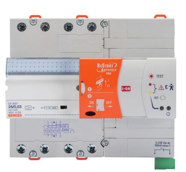
2 DEVICE DESCRIPTION ReStart with Autotest 2P Supply terminals Sliding door left: device ON right: device OFF Synoptic for LED indicator AUTOTEST manual function push-button Device "ON" LED Connection for BUS interface device Output terminals ReStart with Autotest PRO 2P Supply terminals Sliding door left: device ON right: device OFF Synoptic for LED indicator AUTOTEST manual function push-button Device "ON" LED Connection for BUS interface device Output terminals ReStart with Autotest PRO 4P Supply terminals Sliding door left: device ON right: device OFF Synoptic for LED indicator AUTOTEST manual function push-button Device "ON" LED Connection for BUS interface device Output terminals 2
3 AUTOTEST FUNCTION The Autotest function periodically tests the working of the residual current circuit breaker protection. During the test, a bypass circuit ensures electrical continuity meanwhile an additional RCCB protection device guarantees system safety. The automatic reclosing device ensures the automatic resetting of the lever of circuit breaker in ON position. Moreover, pressing the button on the front of the device at any time, Autotest immediately carries out an automatic test on the RCCB without interupting the power supply. This means test can be carried out during normal day-to-day operations without any inconvenience. Electrical diagram Key Bypass circuit Automatic reclosing device Control microprocessor Electrical signals Power supply Periodical test function After installation, it is possible to start up the Autotest function manually (pressing the appropriate button) in order to check if the wiring is correct and to synchronise the periodical test function. Manual start up of Autotest 1 2 Periodical cycle Bypass closure RCCB test Normal operating cycle 4 3 Bypass Automatic reset reopening YES Tripped RCCB? NO Fault signalling 3
4 ReStart with Autotest light signalling ReStart with Autotest is equipped with two LEDs on the front which show the operation conditions of device. Precisely, the right LED is switched on when the device is activated, whereas the left LED shows the operation conditions. ReStart conditions ReStart front Lever position LED indicators Left LED Right LED Aux contact Description MANUAL OPERATION Deactivated I OFF ARD and autotest OFF Deactivated for over 15 minutes I ON ARD and autotest OFF Deactivated 0 OFF ARD and autotest OFF AUTOMATIC OPERATING CYCLE (*) Normal operation I OFF ARD and autotest ON Automatic functions ON Electric circuit check 0 OFF ARD and autotest checks the electric system insulation System failure 0 ON ARD and autotest in block condition due to system fault For PRO versions only, ARD and autotest in standby condition due to system fault Periodic Autotest I/0 OFF Electric circuit check in progress Electric system supplied Device fault 0 ON There is a fault in Restart device after testing RCCB. It is possible to restore the proper functions. Device fault I ON There is a fault in Restart device after testing RCCB. It is possible to restore the proper functions. Device failure I ON ARD and autotest not working Call a technician for replacement Device failure 0 ON ARD and autotest not working Call a technician for replacement (*) Before sliding the plastic cover to the left to activate the device, it is necessary to set the circuit breaker in the "I" position. NOTE: ReStart device can be in block condition (red led fixed) after 4 following trips too (t 60s after previous trip). Key LED OFF LED blinking LED ON (fixed) LED ON (standby) For PRO versions only LED blinking 4
5 ReStart with Autotest operation conditions Autotest function with positive result RCCB working test Main contacts Bypass circuit Device "ON" LED Autotest start < 7s Autotest end t Autotest function with negative result RCCB working test Main contacts Bypass circuit Device "ON" LED t Autotest start < 7s Autotest end Key Closed circuit Device ON Test in progress Device fault 5
6 ReStart function with positive result System check Device "ON" LED tripped < 10s reset t ReStart function with negative result System check Device "ON" LED tripped < 10s Start of block or standby (PRO versions) condition t Key Closed circuit Device ON System check in progress Device block Device in standby (PRO version) 6
 Minimum operating voltage (min Ue) (V) 85% Ue Maximum operating voltage (max Ue): (V) 110% Ue Rated insulation voltage (Ui): (V) 500 Dielectric strength test voltage between pole and earth:")
: (A) IΔc of the associated circuit breaker Number of poles: 2 4 Type of IDP RCCB: AC - A - A[IR] - A[S] Rated current")
7 RESTART RD Technical data TYPE ReStart Rd 2P ReStart Rd PRO 2P ReStart Rd PRO 4P Electrical characteristics Standards: EN Distribution system: TT - TN-S Rated operational voltage (Ue): (V) 230 AC (1) Minimum operating voltage (min Ue) (V) 85% Ue Maximum operating voltage (max Ue): (V) 110% Ue Rated insulation voltage (Ui): (V) 500 Dielectric strength test voltage between pole and earth: (V) 2500 AC for 1 minute Rated impulse withstand voltage (Uimp): (kv) 4 Overvoltage category: III Rated frequency: (Hz) 50 Residual making and breaking capacity (IΔm): (A) IΔm of the associated circuit breaker Rated conditional residual short-circuit current with fuse (IΔc): (A) IΔc of the associated circuit breaker Number of poles: 2 4 Type of IDP RCCB: AC - A - A[IR] - A[S] Rated current (In): (A) Rated residual operating current (IΔn): (ma) Rated non-operating resistance between live parts and earth (Rdo): (kω) 8 (30mA) - 2,5 (100/300/500mA) Rated operating resistance between live parts and earth (Rd): (kω) 16 (30mA) - 5 (100/300/500mA) Power loss at In: (W) Power loss of the associated circuit breaker Off-load absorbed power: (VA) 3 (cosφ=0.4) 4 (cosφ=0.2) Power absorbed during automatic reclosing: (VA) 18 (cosφ=0.5) 45 (cosφ=0.5) Mechanical characteristics Width in DIN modules: 1 3 Reclosing time: (s) 10 Maximum operational frequency: (oper./h) 30 Max mechanical endurance (total no. operations): 4000 Maximum no. of consecutive automatic reclosure operations (2): 3 Counter reset time no. of consecutive automatic reclosure operations: (s) 60 Section of circuit breaker terminals: (mm 2 ) flexible cable: 1x35-2x16-1x16+2x10 rigid cable: 1x35-2x16-1x16+2x10 rated tightening torque: (Nm) 3 (IDP) - 2 (IDP NA) Mounting position: any degree of protection: IP20 (terminals) - IP40 (front) Pollution degree: 2 Operating temperature: ( C) (3) (3) Stocking temperature: ( C) Tropicalization: 55 C - RH 5% characteristics Can be fitted with auxiliary: no yes (with GWD051) already integrated in the ReStart Type of contact: - Photomos (potential free contact) Operating voltage: (V) AC/DC Operating current: (ma) - 0,6 (min) cosφ=1 (max) Operating frequency: (Hz) - 50 Category of use: - AC12 Operating mode: - NO\NC\NO as signal of handle position Terminal section: (mm 2 ) Rated tightening torque: (Nm) ReStart function Automatic reclosure for untimely tripping: Earth failure test: Earth leakage check: Interruption of reclosure operation in the event of a fault: Signalling of reclosure operation in progress: Light signalling of failure: Activation / exclusion of ReStart function: for remote operating status access: Internal electrical protection: PTC PTC PTC (1) Power supply 230V phase-neutral (2) In the absence of a system fault (3) Average daily temperature +35 C 7
: (V) 230 AC (2) Minimum operating voltage (min Ue) (V) 85% Ue Maximum operating voltage (max Ue): (V) 110% Ue Rated insulation voltage (Ui): (V) 500 Dielectric strength")
: (A) IΔm of the associated circuit breaker Number of poles: 2 4 Type of MDC RCBO: AC - A - A[IR] - A[S] Type of MT+BD RCBO: - AC - A - A[IR] - A[S] Rated current (In): (A) from 6 to 32 from 1")
 - Rated operating resistance between live parts and earth (Rd): (kω) 16 (30mA) - 5 (300mA) 16 (30mA) - 5 (300/500/1000mA) - Rated non-operating resistance between live parts")
8 RESTART RM Technical data TYPE ReStart Rm 2P ReStart Rm PRO 2P ReStart Rm PRO 4P Rm TOP CM Electrical characteristics Standards: EN Distribution system: TT - TN-S TT - TN - IT (1) TT-TN-IT Rated operational voltage (Ue): (V) 230 AC (2) Minimum operating voltage (min Ue) (V) 85% Ue Maximum operating voltage (max Ue): (V) 110% Ue Rated insulation voltage (Ui): (V) 500 Dielectric strength test voltage between pole and earth: (V) 2500 AC for 1 minute Rated impulse withstand voltage (Uimp): (kv) 4 Overvoltage category: III Rated frequency: (Hz) 50 Residual making and breaking capacity (IΔm): (A) IΔm of the associated circuit breaker Number of poles: 2 4 Type of MDC RCBO: AC - A - A[IR] - A[S] Type of MT+BD RCBO: - AC - A - A[IR] - A[S] Rated current (In): (A) from 6 to 32 from 1 to 63 Rated residual operating current (IΔn): (ma) Rated non-operating resistance between live parts and earth (Rdo): (kω) 8 (30mA) (300mA) 8 (30mA) (300/500/1000mA) - Rated operating resistance between live parts and earth (Rd): (kω) 16 (30mA) - 5 (300mA) 16 (30mA) - 5 (300/500/1000mA) - Rated non-operating resistance between live parts (Rcco): (Ω) Rated operating resistance between live parts (Rcc): (Ω) Power loss at In: (W) Power loss of the associated circuit breaker Off-load absorbed power: (VA) 3 (cosφ=0.4) 16 (cosφ=0.2) 15 (cosφ=0.1) 0 (cosφ=0.2) Power absorbed during automatic reclosing: (VA) 18 (cosφ=0.5) 34 (cosφ=0.7) 30 (cosφ=0.6) 30 (cosφ=0.6) Reclosing control: automatic automatic / remote (3) remote (3) Mechanical characteristics Width in DIN modules: Reclosing time: (s) 10 3 (without system test) 10 (with system test) 3 Remote control opening time: (s) - 2 Maximum operational frequency: (oper./h) 30 Max mechanical endurance (total no. operations): Maximum no. of consecutive automatic reclosure operations (4) : 3 - Counter reset time no. of consecutive automatic reclosure operations: (s) 60 - Section of circuit breaker terminals: (mm 2 ) flexible cable: 1x35-2x16-1x16+2x10 rigid cable: 1x35-2x16-1x16+2x10 Rated tightening torque: (Nm) 2 Mounting position: any Degree of protection: IP20 (terminals) - IP40 (front) Pollution degree: 2 Operating temperature: ( C) (5) (5) Stocking temperature: ( C) Tropicalization: 55 C - RH 5% characteristics Can be fitted with auxiliary: no yes (with GWD051) already integrated in already integrated in the ReStart in the ReStart in the ReStart already integrated already integrated the ReStart Type of contact: - Photomos (potential free contact) Changeover Photomos (potential free contact) Changeover Operating voltage: (V) AC/DC 230 AC/ 30 DC AC/DC 230 AC/ 30 DC Operating current: (ma) - 0,6 (min) cosφ=1 (max) 1,5 a.c. / 0,8 d.c. 0,6 (min) cosφ=1 (max) 1,5 a.c. / 0,8 d.c. Operating frequency: (Hz) - 50 Category of use: - AC12 Operating mode: - NO/NC/NO as signal of handle position CO Terminal section: (mm 2 ) Rated tightening torque: (Nm) ReStart function Automatic reclosure for untimely tripping: Earth leakage check: Short-circuit check: (1) For IT system reclosing without fault check (2) Power supply 230V phase-neutral (3) Impulse duration 200ms (4) In the absence of a system fault (5) Average daily temperature +35 C (6) Automatic reclosure delay time: 0-1h 8 NO/NC/ INTERMITTENT Adjustable insulation threshold: Continuous system check: Adjustable reset standby time (6) : Adjustable reclosing mode: Interruption of reclosure operation in the event of a fault: Signalling of reclosure operation in progress: Light signalling of failure: Activation / exclusion of ReStart function: for remote operating status access: Internal electrical protection: PTC PTC PTC PTC PTC CO


9 DEVICE DESCRIPTION ReStart Rd 2P ReStart Rm 2P ReStart power supply cables Short-circuit module ReStart power supply cables Cover opened: ReStart OFF Cover closed: ReStart ON Signalling LED Synoptic for signalling LED Cover opened: ReStart OFF Cover closed: ReStart ON Signalling LED Synoptic for signalling LED Cables for system ckecking Cables for system ckecking ReStart Rd PRO 2P ReStart Rm PRO 2P ReStart power supply cables Short-circuit module ReStart power supply cables Cover opened: ReStart OFF Signalling LED Cover opened: ReStart OFF Signalling LED Cover closed: ReStart ON Synoptic for signalling LED Cover closed: ReStart ON Synoptic for signalling LED Cables for system ckecking Cables for system ckecking ReStart Rd PRO 4P ReStart Rm PRO 4P Short-circuit module ReStart power supply cables ReStart power supply cables Sliding cover left: ReStart ON right: ReStart OFF Cables for system ckecking Synoptic for signalling LED ReStart ON LED Operation status LED Auxiliary contact Sliding cover left: ReStart ON right: ReStart OFF Cables for system ckecking Synoptic for signalling LED ReStart ON LED Operation status LED Auxiliary contact ReStart Rm TOP ReStart Cm Selector UP: ON; DOWN: OFF mode Operating mode Synoptic for LED indicator Operation status LED mode Selector UP: ON; DOWN: OFF Device "ON" LED Adjustable reset time
10 AUTOMATIC RECLOSING FUNCTION ReStart with Autotest, Rd and Rm The automatic reclosing is carried out after an untimely tripping of the circuit breaker but only after an electrical circuit check. If a fault is found, the device sets itself on block condition and signals the fault by means of the front LED indicator. (fixed) Device block Tripping Electric circuit check NO Check OK? YES automatic reclosing in progress Reclosing carried out RESTART WITH AUTOTEST, RD AND RM PRO VERSION The circuit breaker is reclosed after an untimely tripping of the circuit breaker but only after a system check. When the system check gives a negative result, the device goes into standby and signals this condition by means of the frontal LED indicator. System checks will then be carried out at 2' intervals, and the device will only reclose when the result of the test is positive. If no positive result is obtained, the device will remain in standby until the next test, or until a manual reset. The auxiliary contact signals the system fault. Reclosing YES (standby) YES Tripping Electric circuit check OK? Alarm ON Auxiliary contact ON Standby 2' Electric circuit check OK? NO Key LED blinking 0.5s 0.5s 0.5s 0.5s LED ON (standby) 5s 5s LED ON (fixed) 10
11 System fault check Every device belonging to ReStart range is equipped with internal electronic circuit which is able to check the system and then to carry out the automatic reclosing of the circuit breaker if the value of the insulation resistance measured by the electronic circuit is compatible with the predefined safety values. During the system check ReStart injects a pulsant unidirectional current type in order to check the status of the system. The intensity of this current is extremely low in order to guarantee always the people safety. The figures below are given as an example to show the route taken by the current during system check for TT distribution systems both single and three phase. ReStart RM, in addition to the check of the insulation resistance, carries out a system short circuit check. ReStart 2P Earthing fault Short-circuit Current circulation with earth failure during system check Rt: installation earth resistance Rtc: cabin earth resistance Rg: fault resistance Current circulation with failure due to short-circuit during system check ReStart 4P Earthing fault Short-circuit RESTART PRO 4P RESTART RM PRO 4P Current circulation with earth failure during system check Rt: installation earth resistance Rtc: cabin earth resistance Rg: fault resistance Current circulation with failure due to short-circuit during system check 11
12 ReStart Rd and Rm light signalling ReStart Rd and Rm are equipped with one LED on the front which shows the operation conditions of the device. ReStart Rd ReStart conditions ReStart front Lever position Indicator LED Description MANUAL OPERATION Deactivated I Reset device OFF Deactivated 0 Reset device OFF AUTOMATIC OPERATING CYCLE (*) Normal operation I Reset device ON Electric circuit check 0 Reset device in electric system insulation check condition. System failure 0 Reset device in block condition due to low insulation of downstream electric system. (*) Before sliding the plastic cover to the left to activate the device, it is necessary to set the associated circuit breaker in the "I" position. NOTE: ReStart device can be in block condition (red led fixed) after 4 following trips too (t 60s after previous trip). ReStart Rm ReStart conditions ReStart front Lever position Indicator LED Description MANUAL OPERATION Deactivated I Reset device OFF Deactivated 0 Reset device OFF AUTOMATIC OPERATING CYCLE (*) Normal operation I Reset device ON Electric circuit check 0 Reset device in electric system insulation and short-circuit check conditions. System failure 0 Reset device in block condition due to low insulation or short-circuiting fault of downstream electric system (*) Before sliding the plastic cover to the left to activate the device, it is necessary to set the associated circuit breaker in the "I" position. NOTE: ReStart device can be in block condition (red led fixed) after 4 following trips too (t 60s after previous trip). 12
13 ResStart Rd and Rm operation conditions ReStart function with positive result System check < 10 s tripped reset ReStart function with negative result System check < 10 s tripped Start of block condition Key Closed circuit System check in progress Device block 13
14 ReStart Rd and Rm PRO light signalling for circuit breakers 2 poles ReStart Rd and Rm PRO for circuit breakers 2 poles are equipped with one LED on the front which shows the operation conditions of device. ReStart conditions ReStart front Lever position LED indicators Description MANUAL OPERATION Deactivated I Reset device OFF Deactivated 0 Reset device OFF AUTOMATIC OPERATING CYCLE (*) Normal operation I Reset device ON Electric circuit check 0 Reset device in system check condition. System insulation fault 0 (standby) Reset device in standby conditions due to insulation fault of downstream electric system (*) Before sliding the plastic cover to the left to activate the device, it is necessary to set the associated circuit breaker in the I position. NOTE: ReStart device can be in block condition (red led fixed) after 4 following trips too (t 60s after previous trip) Specifically, Restart Rm PRO may have the following operation condition: ReStart conditions ReStart front Lever position LED indicators Description AUTOMATIC OPERATION System short-circuit fault 0 (fixed) Reset device in block condition due to short-circuit fault of downstream electric system Key LED OFF LED blinking LED ON (standby) For PRO versions only LED ON (fixed) 14
15 Restart Rd and Rm PRO operation conditions for circuit breakers 2 poles ReStart function with positive result System check < 10 s tripped reset ReStart function with negative result System check < 10 s tripped Start of standby condition Key Closed circuit System check in progress Device standby 15
16 ReStart Rd and Rm PRO light signalling for circuit breakers 4 poles ReStart PRO for circuit breaker 4 poles is equipped with two LEDs on the front which show the operation conditions of device. The right-hand LED is switched on when the device is activated, and the left-hand LED shows the operation conditions. ReStart conditions ReStart front Lever position LED indicators Left LED Right LED Aux contact Description MANUAL OPERATION GW067 EN50557 PRO Deactivated I OFF Reset device OFF Deactivated for over 15 minutes GW067 EN50557 PRO I ON Reset device OFF GW067 EN50557 PRO Deactivated 0 OFF Reset device OFF AUTOMATIC OPERATING CYCLE (*) GW067 EN50557 PRO Normal operation I OFF Reset device ON GW067 EN50557 PRO Electric circuit check 0 OFF Reset device in system check condition. System insulation fault GW067 EN50557 PRO 0 (standby) ON Reset device in standby conditions due to insulation fault of downstream electric system (*) Before sliding the plastic cover to the left to activate the device, it is necessary to set the associated circuit breaker in the I position. NOTE: ReStart device can be in block condition (red led fixed) after 4 following trips too (t 60s after previous trip) Specifically, Restart Rm PRO may have the following operation condition: ReStart conditions ReStart front Lever position LED indicators Left LED Right LED Aux contact Description AUTOMATIC OPERATION System short-circuit fault GW086 EN50557 PRO 0 (fixed) ON Reset device in block condition due to short-circuit fault of downstream electric system Key LED OFF LED blinking LED ON (standby) For PRO versions only LED ON (fixed) 16
17 Restart Rd and Rm PRO operation conditions for circuit breaker 4 poles ReStart function with positive result System check Device "ON" LED tripped < 10 s reset t ReStart function with negative result System check Device "ON" LED tripped < 10 s Start of standby condition t Key Closed circuit Device ON System check in progress Device standby 17
18 ReStart Rm TOP light signalling ReStart Rm TOP is equipped with two LEDs on the front which show the operation conditions of the device. In addition, by adjusting the two trimmers you can select the operation mode. GW083 ReStart conditions ReStart front Lever position Left LED LED indicators Aux Right LED contact 1 Aux contact 2 Description GW083 MANUAL OPERATION Deactivated I OFF ON (OFF)* Device OFF GW083 Deactivated 0 OFF OFF Device OFF GW083 AUTOMATIC OPERATING CYCLE GW083 Normal operation I OFF ON Device ON GW083 Electric circuit check 0 OFF OFF Device in system check condition GW083 System failure 0 ON OFF Device in standby due to system fault GW083 (*) If it has been set as fault indicator switch. Key Setting as motor operating LED OFF Push-button command LED blinking LED ON (standby) Cyclical command Setting of Aux contact 2 Auxiliary switch for open/closed position Lever in ON Lever in OFF Held command for fault indicator switch Lever in ON Lever in OFF (tripped) NOTE: to change the function Aux contact 2, from open/closed position to fault indicator switch and viceversa, it's required to turn the selector by screwdriver and to make an automatic reclosing cycle. 18

19 BUS RS485 Communication interface module Technical data Code: GW02 Rated operational voltage (Ue): (V) 230 a.c. Minimum operating voltage (min Ue): (V) 85% Ue Maximum operating voltage (max Ue): (V) 110% Ue Rated impulse voltage (Uimp): (kv) 4 Rated frequency: (Hz) 50 Width in DIN modules: 1 Communication protocol: modbus RS485 Number of addresses: 1 Transmission speed: baud rate Coupled with: ReStart with Autotest (2 e 4 pole) ReStart Rm PRO (4 pole) ReStart Rd PRO (4 pole) Rated tightening torque: (Nm) 0,4 Power loss: (W) 1 Degree of protection: IP20 Operating temperature: ( C) (1) Maximum conductor cross section: (mm²) 2,5 Sealable: yes (1) Average daily temperature +35 C Device description BUS RS485 communication interface module input cables supply Addressing selector (x10) Addressing selector (x1) BUS RS 485 output cables Connection example x x x x x x1 120 Ω D(-) GND D(+) RS485 CONVERTER USB ETHERNET 1


20 0 ReStart Application examples ReStart PRO and ReStart Rm TOP With Restart PRO it is possible to monitor the insulation level after tripping for an indefinite period of time (until acceptable values are obtained and the automatic reset operation is performed). This control system is indispensable where the system's insulation level can suddenly drop, due to weather conditions, and then rise thus allowing reset operations once optimal conditions are re-established. SPECIFICATIONS TYPICAL SYSTEMS - Lighting in public places OUTDOOR SYSTEMS - Outdoor lighting in gardens and squares - Exposure to atmospheric disturbance - Sporting facilities - Insulation levels depending on weather conditions (temperature and humidity) - Traffic lights - Presence of electronic power supplies - Extensive damage due to blackout - Difficult accessibility of electrical circuit - Signalling - Pollution control stations - Telecommunication installations - Radio links - Traffic-information panels - Advertising hoardings - Small, medium, and large tertiary sector - Industrial plants INDOOR SYSTEMS - Strong presence of electronic power supplies - Extensive damage due to blackout - Need for guaranteed service continuity - Sensitivity to disturbance induced by mains supply and by atmospheric conditions - Insulation levels depending on weather and operating conditions - Data processing centres - Garages - Pumping systems - Catering - Supermarkets - Ice-cream shops - Alarm system protection - CCTV system protection - Access monitoring system protection - Door and automatic gate protection 20 Technical Information Version 2.1
21 Dimension tables ReStart with Autotest , POLE 4 POLE ReStart Rd and Rd PRO 2P ReStart Rm and Rm PRO 2P ,5 42, ,
22 ReStart Rd PRO 4P SET 7 ReStart Rd Rm PRO 4P , , SET 35 SET
23 ReStart Rm TOP ReStart Cm BUS RS485 Interface module
isw switches Control Local control IEC/EN , isw switch with indicator light. IEC/EN , isw switch without indicator light.
 isw switches DB88 PB0566-40 Position contact indication b Suitable for industrial isolation according to IEC/EN 60947-3 standard. b The presence of the green strip guarantees physical opening of the contacts
Btdin RCD Add-on modules 63A for MCBs 1,5 modules per pole
 Index Pages 1. Descripton... 2 2. Product range... 2 3. Overall dimensions... 2 4. Fixing Connection... 3 5. Generl characteristics... 4 6. Compliance - Approvals... 6 7. Curves... 7 8. Auxiliares and
V2UM230V10 Art.Nr.: V2UM230V10P Art.Nr.: Control elements. Tripping delay. Function selector. Status indication 230 V AC/DC
 P AC/DC voltage monitoring Multifunction Supply voltage 24 V DC or 230V AC/DC Supply circuit = Measuring circuit 1 change-over contact Width 22,5 mm Control elements Tripping delay Maximum threshold Minimum
V2IM10AL10 Art.Nr.: V2IM10AL10P Art.Nr.: Control element. Tripping delay. Function selector. Status indication 24...
 P AC/DC current monitoring Multifunction Supply voltage 24-240V DC or 110-240V AC 1 change-over contact Width 22,5 mm Control element Tripping delay Maximum threshold Minimum threshold Function selector
Single phase meter with direct connection and pulse or Modbus RS485 output
 87045 LIMOGES Cedex Telephone: +33(0)5 55 06 87 87 Fax: +33(0)5 55 06 88 88 Single phase meter with direct connection CONTENTS PAGES 1. Description, usage... 1 2. Range... 1 3. Dimensions... 1 4. Positioning...
Technical features table for miniature circuit-breakers SH 200 Series
 Technical features table for miniature circuit-breakers SH 00 Series Standards Poles Tripping characteristics I n A frequency f Hz insulation voltage U i acc. to IEC/EN 60664-1 V Overvoltage category Pollution
Residual Current Operated Circuit-Breakers (RCCBs)
") Product Overview Residual Current Operated Circuit-Breakers (RCCBs) Residual current operated circuit-breakers Number of poles Rated current A Rated residual current ma MW Auxiliary contacts can be mounted
Product Overview Residual Current Operated Circuit-Breakers (RCCBs) Residual current operated circuit-breakers Number of poles Rated current A Rated residual current ma MW Auxiliary contacts can be mounted
Modeion OTHER ACCESSORIES OF MOULDED CASE CIRCUIT BREAKERS
 OTHER ACCESSORIES OF MOULDED CASE CIRCUIT BREAKERS P Other accessories DELAY UNIT Type Product code Description Weight [kg] Package [pc] BZ-BX-X230-A 36696 enables to delay the undervoltage release tripping
Add-on modules DX 3 63A for MCBs DX 3 1,5 modules per pole
 87045 LIMOGES Cedex Telephone number: +33 (0)5 55 06 87 87 Fax: +33 (0)5 55 06 88 88 Add-on modules DX 3 63A for MCBs CONTENTS PAGE 1. Description, use... 1 2. Range... 1 3. Overall dimensions... 1 4.
 Phase control Single function phase control relay - 7.5 mm Control of -phase networks: phase sequence, total phase failure Multi-voltage from x 08 to x 480 V Controls its own supply voltage True RMS measurement
itl impulse relays IEC/EN itls: IEC/EN itls b Allows remote indication of its operating state (open/closed)
") DB123399 DB116619 Country approval pictograms itl, itli, itls, itlc, itlm IEC/EN 60669-2-2 itls: IEC/EN 60947-5-1 Impulse relays B106126-34 B106128-34 itl b The impulse relays are used to control, by means
DB123399 DB116619 Country approval pictograms itl, itli, itls, itlc, itlm IEC/EN 60669-2-2 itls: IEC/EN 60947-5-1 Impulse relays B106126-34 B106128-34 itl b The impulse relays are used to control, by means
FIB / FIC. r with Overcurrent Protection (RCBO) Doepke. » effi cient. » reliable. » fl exible. » future-oriented
 Doepke. » effi cient. » reliable. » fl exible. » future-oriented") Doepke The experts in residual current protection technology Residual Current Circuit-Breakers it- r with Overcurrent Protection (RCBO) FIB / FIC» effi cient» reliable» fl exible» future-oriented Doepke
Doepke The experts in residual current protection technology Residual Current Circuit-Breakers it- r with Overcurrent Protection (RCBO) FIB / FIC» effi cient» reliable» fl exible» future-oriented Doepke
3-phase meter with direct connection and pulse or Modbus RS485 output
 87045 LIMOGES Cedex Telephone: +33 (0)5 55 06 87 87 Fax: +33 (0)5 55 06 88 88 3-phase meter with direct connection and CONTENTS PAGES 1. Description, usage... 1 2. Range... 1 3. Dimensions... 1 4. Positioning...
Protection relays and transformers
 NEW ZEALAND WWW.LPINZ.CO.NZ Unit 6/22 Moselle Ave, Henderson, Auckland, New Zealand PO Box 21-872, Henderson, Auckland, New Zealand Phone:+64 9 833 5749 Email:info@LPINZ.co.nz Web: www.lpinz.co.nz Protection
27/04/2015
 Modular Carril DIN 35 mm HIL Part number 84871120 Control of AC and DC currents Automatic recognition of AC/DC Measurement ranges from 2 ma to 10 A Choice between over and undercurrent True RMS measurement
Type CP-S, CP-C & CP-A Switch mode
 Switch mode power CP-S, CP-C & CP-A Switch mode Characteristics CP-S and CP-C range Output current 5 A, 10 A and 20 A Integrated power reserve of up to 50 % 5 A and 10 A devices with pluggable connecting
ISOSCAN EDS460-DG. Insulation fault locator for DC IT systems with high system leakage capacitances
 ISOSCAN Insulation fault locator for DC IT systems with high system leakage capacitances _D00108_00_D_XXEN/05.2015 ISOSCAN Insulation fault locator for DC IT systems with high system leakage capacitances
Type Nominal voltage (V) Code HSV V
 Code HSV V") Speed control Speed control relay - mm Control of overspeed, underspeed, operating rate, stopping Measurement via discrete sensors - -wire PNP or NPN, Namur, voltage 0-0V or volt-free contact type Works
Speed control Speed control relay - mm Control of overspeed, underspeed, operating rate, stopping Measurement via discrete sensors - -wire PNP or NPN, Namur, voltage 0-0V or volt-free contact type Works
Page 13-2 Page Page 13-7
 Page -2 Page -6 MINIATURE CIRCUIT BREAKERS UP TO 63A 1P, 1P+N, 2P, 3P and 4P versions IEC rated current In: 1-63A IEC short-circuit capacity Icn: 10kA (6kA for 1P+N) Trip characteristic curve: Type B,
Instantaneous Overcurrent Relay
 Midos Type MCRI Instantaneous Overcurrent Relay Features High speed operation Not slowed by dc transients Settings readily adjustable on relay front plate Two phase and earth fault relay Figure 1: Type
38 Series - Relay interface modules A. Features /
 Series - Relay interface modules 0.1-2 - 6-8 A Features 1 Pole - 6 A electromechanical relay interface modules, 6.2 mm wide. Ideal interface for PLC and electronic systems Sensitive DC coil or coil versions
Insulation monitoring relay CM-IWS.1 For unearthed AC, DC and mixed AC/DC systems up to U n = 250 V AC and 300 V DC
 Data sheet Insulation monitoring relay CM-IWS.1 For unearthed AC, DC and mixed AC/DC systems up to U n = 250 V AC and 300 V DC The CM-IWS.1 serves to monitor insulation resistance in accordance with IEC
Residual Current Operated Circuit-Breakers (RCCBs)
") Product overview Residual Current Operated C ircuit-breakers (RCCBs) Number of poles Rated fault current I n ma Rated current I n A MW Auxiliary switches can be mounted (Type A) (Type B) 5SM1and 5SM3 RCCBs
Product overview Residual Current Operated C ircuit-breakers (RCCBs) Number of poles Rated fault current I n ma Rated current I n A MW Auxiliary switches can be mounted (Type A) (Type B) 5SM1and 5SM3 RCCBs
PRELIMINARY DATA SHEET RI-D140. Three Phase Multifunction DIN Rail Energy Meter (MID Certified) MID
 MID") RI-D140 Three Phase Multifunction DIN Rail Energy Meter (MID Certified) Four module DIN rail mounted Energy pulse LED True RMS measurement Cost effective and accurate Modbus communication -/1A or -/5A
RI-D140 Three Phase Multifunction DIN Rail Energy Meter (MID Certified) Four module DIN rail mounted Energy pulse LED True RMS measurement Cost effective and accurate Modbus communication -/1A or -/5A
(1,5 modules per pole)
") 87045 LIMOGES Cedex Telephone: +33 5 55 06 87 87 FAX: +33 5 55 06 88 88 DX 3 MCB 25kA 80A to 125A CONTENTS PAGES 1. Description - Use... 1 2. Range... 1 3. Overall dimensions... 1 4. Preparation - Connection...
87045 LIMOGES Cedex Telephone: +33 5 55 06 87 87 FAX: +33 5 55 06 88 88 DX 3 MCB 25kA 80A to 125A CONTENTS PAGES 1. Description - Use... 1 2. Range... 1 3. Overall dimensions... 1 4. Preparation - Connection...
Thermistor motor protection relays
 Thermistor motor protection relays Content Benefits and advantages... / 68 Selection table... / 68 Ordering details CM-MSE... / 69 CM-MSS... / 69 CM-MSN... / 7 PTC sensor C0... / 7 Technical data... /
BU: EPBP GPG: DIN Rail Products Devices for the permanent control of insulation on supply lines for medical locations ISOLTESTER-DIG-RZ/RS/PLUS
 INSTRUCTION MANUAL BU: EPBP GPG: DIN Rail Products Devices for the permanent control of insulation on supply lines for medical locations ISOLTESTER-DIG-RZ/RS/PLUS 1/23 More information than that reported
RI-D440. Three Phase easywire Multifunction DIN Rail Energy Meter. Telephone : +44 (0) Displayed Parameters
 Displayed Parameters") RI-D440 Three Phase easywire Multifunction DIN Rail Energy Meter Four module DIN rail mounted Energy pulse LED 330mV Input from easywire CTs (or -/1A and -/5A current transformer input with TAS-SCTEWA
RI-D440 Three Phase easywire Multifunction DIN Rail Energy Meter Four module DIN rail mounted Energy pulse LED 330mV Input from easywire CTs (or -/1A and -/5A current transformer input with TAS-SCTEWA
RE17RMMW time delay relay 10 functions - 1 s..100 h V AC/DC - 1 OC
 Characteristics time delay relay 10 functions - 1 s..100 h - 12..240 V AC/DC - 1 OC Product availability : Stock - Normally stocked in distribution facility Price* : 75.00 USD Main Range of product Product
58 SERIES. Relay interface modules 7-10 A 58.P3 58.P4
 58 58 3 & 4 CO relay interface modules, 31 mm wide with Push-in terminals Ideal interface for PLC and electronic systems 58.P3 58.P4 Type 58.P3 3 CO 10 A Push-in terminals Type 58.P4 4 CO 7 A Push-in terminals
RI-F200 Series. Single and Three Phase Multifunction Energy Meter. Telephone : +44 (0) Displayed Parameters
 Displayed Parameters") RI-F200 Series Single and Three Phase Multifunction Energy Meter DIN 96 panel mounted -/1A or -/5A current transformer input Single phase or three phase network compatible Programmable voltage and current
RI-F200 Series Single and Three Phase Multifunction Energy Meter DIN 96 panel mounted -/1A or -/5A current transformer input Single phase or three phase network compatible Programmable voltage and current
AC/DC. Monitoring Technique. VARIMETER IMD Insulation monitor RN 5897/300
 Monitoring Technique VARIMETER IMD Insulation monitor RN 5897/300 0274214 Your Advantages For mobile generator sets according to DIN VDE 0100-551 Preventive fire and system protection Detection of symmetric
RCMS460 and RCMS490 Series
 4 T M RCMS460 and RCMS490 Series Digital Multi-Channel Ground Fault Monitor / Ground Fault Relay Grounded and High-Resistance Grounded AC/DC Systems Technical Bulletin NAE1042060 / 04.2013 BENDER Inc.
Dipl.-Ing. W. Bender GmbH & Co. KG Londorfer Str Grünberg Tel.: Fax:
 Dipl.-Ing. W. Bender GmbH & Co. KG Londorfer Str. 65 35305 Grünberg Tel.: 06401 807-0 Fax: 06401 807-259 Insulation fault locator Insulation fault locator for DC IT systems with high system leakage capacitances
RE17LLBM asymmetrical flashing relay s V AC - solid state output
 Characteristics asymmetrical flashing relay - 0.1..1 s - 24..240 V AC - solid state output Product availability : Non-Stock - Not normally stocked in distribution facility Price* : 75.00 USD Main Range
Coupling unit CM-IVN For expansion of the insulation monitoring relay CM-IWN.x measuring range up to U n = 690 V AC and 1000 V DC
 Data sheet Coupling unit CM-IVN For expansion of the insulation monitoring relay CM-IWN.x measuring range up to U n = 690 V AC and 1000 V DC The CM-IVN serves to extend the measuring range of the insulation
Components for Marine applications
 Components for Marine applications Imagination GE imagination at work. at work v. 10-2015 GE Industrial Solutions Leading the future of electrification GE Industrial Solutions is leading the future of
Btdin RCD Add-on Modules 32A - 63A for M.C.Bs 1 module per pole
 Index Pages 1. Descripton... 2 2. Product range... 2 3. Overall dimensions... 2 4. Fixing Connection... 3 5. Generl characteristics.... 4-6 6. Compliance - Approvals... 6 7. Curves... 7 1 / 7 1. DESCRIPTION
3 - Protection components Circuit-breakers
 Contents - Protection components Circuit-breakers for the motor protection Selection guide..............................................page /2 Thermal-magnetic motor circuit-breakers Selection guide..............................................page
ISOMETER iso685- -B. Insulation monitoring device for unearthed AC, AC/DC and DC systems (IT systems) Preliminary data sheet
 Preliminary data sheet") Insulation monitoring device for unearthed AC, AC/DC and DC systems (IT systems) Preliminary data sheet iso685-x-b_d00177_04_d_xxen/04.2018 Insulation monitoring device for unearthed AC, AC/DC and DC systems
Insulation monitoring device for unearthed AC, AC/DC and DC systems (IT systems) Preliminary data sheet iso685-x-b_d00177_04_d_xxen/04.2018 Insulation monitoring device for unearthed AC, AC/DC and DC systems
VEO. V2PF480Y/277VSY01 Art.Nr.: V2PF480Y/277VSY01P Art.Nr.: TECHNICAL DATA
 P Monitoring of phase sequence and phase loss Monitoring of asymmetry Supply voltage 208-480 V AC Supply circuit = measuring circuit 1 change-over contact Width 22,5 mm Control elements Asymmetry Status
NPRG860 & NPRG870 perform synchronization and paralleling of generators with electrical network. NPRG860 features a speed adjustment function.
 REGULATION AUTOMATIC SYNCHRONIZER for GENERATOR NPRG860 & NPRG870 perform synchronization and paralleling of generators with electrical network. NPRG860 features a speed adjustment function. NPRG870 adds
NPRG860 NPRG870 REGULATION. Automatic Synchronizer for Generator
 REGULATION Automatic Synchronizer for Generator NPRG860 & NPRG870 perform synchronization and paralleling of generators with electrical network. NPRG860 features a speed adjustment function. NPRG870 adds
INSTRUCTIONS MANUAL DEVICE FOR THE PERMANENT CONTROL OF INSULATION ON THE SUPPLY LINES IN MEDICAL PRACTICE PLACES INSTALLATIONS HRI-R40W
 Page 2 / 16 INDEX: GENERAL TYPES ACESSORIES AND OPTIONS INSTALLATION WIRING DIAGRAMS CONNECTING TERMINALS DIAGRAMS WIRING DIAGRAM DESCRIPTION WORKING DESCRIPTION AND KEYBOARD WORKING DESCRIPTION AND PROGRAMMING
RE17RMMU time delay relay 10 functions - 1 s..100 h V AC - 1 OC
 Characteristics time delay relay 10 functions - 1 s..100 h - 24..240 V AC - 1 OC Product availability : Stock - Normally stocked in distribution facility Price* : 62.00 USD Main Range of product Product
VEO. V2PF480Y/277VS01 Art.Nr.: B TECHNICAL DATA
 Monitoring of phase sequence and phase loss Monitoring of asymmetry Supply voltage 208-480 V AC Supply circuit = measuring circuit 1 change-over contact Width 22,5 mm Status indication LED U: Supply voltage
Btdin RCD Add-on Modules 32A - 63A for M.C.Bs 1 module per pole
 Index Pages 1. Descripton... 2 2. Product range... 2 3. Overall dimensions... 2 4. Fixing Connection... 3 5. Generl characteristics.... 4-6 6. Compliance - Approvals... 6 7. Curves... 7 1 / 7 1. DESCRIPTION
Three-phase monitoring relay CM-PFS
 Data sheet Three-phase monitoring relay CM-PFS The CM-PFS is a three-phase monitoring relay that is used to monitor three phase mains for incorrect phase sequence and phase failure. All devices are available
Liquid level monitoring relay CM-ENS.2x
 Data sheet Liquid level monitoring relay CM-ENS.2x The CM-ENS.2x is served to regulate and control liquid levels and ratios of mixtures of conductive fluids. It can be used for overflow protection, dry
VI 3 - i TABLE OF CONTENTS
 VI 3 - i TABLE OF CONTENTS 3 PROJECT SPECIFIC DATA... 1 3.1 DEFINITIONS... 1 3.1.1 Design Data, High and Medium Voltage... 1 3.1.2 Design Data, Low Voltage Equipment... 2 3.1.3 Phase Relationship... 3
Protection components
 Multifunction protection relays LT-P Environment Conforming to standards IEC 947-4-1, IEC 34-11, IEC 755, VDE 010, VDE 00. &Ãmarking Meets the essential requirements of the Low Voltage equipment (LV) &
Datasheet - PROTECT-IE-02
 Print - Create PDF - Create EXCEL file 20.04.2011-18:28:57h Datasheet - PROTECT-IE-02 Input expander / PROTECT-IE Input expander Input for up to 4 sensors per interface e.g.: magnetic safety switches type
Temperature monitoring relays CM-TCS Monitoring relays for monitoring temperatures with a PT100 sensor (2- or 3-wire connection)
") Data sheet Temperature monitoring relays CM-TCS Monitoring relays for monitoring temperatures with a PT100 sensor (2- or 3-wire connection) The temperature monitoring relays CM-TCS monitor overtemperature,
Data sheet Temperature monitoring relays CM-TCS Monitoring relays for monitoring temperatures with a PT100 sensor (2- or 3-wire connection) The temperature monitoring relays CM-TCS monitor overtemperature,
RE17RAMU on-delay timing relay - 1 s..100 h V AC - 1 OC
 Characteristics on-delay timing relay - 1 s..100 h - 24..240 V AC - 1 OC Product availability : Stock - Normally stocked in distribution facility Price* : 42.90 USD Main Range of product Product or component
Easy measuring, reliable monitoring and flexible planning - the EMR, ETR and EMT relays
 EMR6 EMT6 ETR4 www.eaton.eu Easy measuring, reliable monitoring and flexible planning - the EMR, ETR and EMT relays The measuring and monitoring of industrial applications made simple - with the EMR6 With
PEM353. Universal measuring device
 353 Universal measuring device 353_D00335_00_D_XXEN/06.2018 353 Universal measuring device Product description The digital universal measuring device 353 is used to record and display measured quantities
ISOMETER iso685- Insulation monitoring device for unearthed AC, AC/DC and DC systems (IT systems)
") Insulation monitoring device for unearthed AC, AC/DC and DC systems (IT systems) iso685-x_d00022_08_d_xxen/04.2018 Insulation monitoring device for unearthed AC, AC/DC and DC systems (IT systems) Product
Insulation monitoring device for unearthed AC, AC/DC and DC systems (IT systems) iso685-x_d00022_08_d_xxen/04.2018 Insulation monitoring device for unearthed AC, AC/DC and DC systems (IT systems) Product
Thermistor motor protection relays
 Thermistor motor protection relays Content Benefits and advantages... / 68 Selection table... / 68 Ordering details CM-MSE... / 69 CM-MSS... / 69 CM-MSN... / 7 PTC sensor C0... / 7 Technical data... /
Installation- / Monitoring Technique
 Installation- / Monitoring Technique VARIMETER Insulation fault locator RR 5887 0269248 Product Description 4-channel design The locating current generator RR 5886 in connection with the insulation fault
02/11/2015
 Modem communication plug and play solutions GSM Part number 88970119 For remote control of your application Automatic notification of alarms via SMS (GSM Modem) / email or on a PC with M3 ALARM software.
Circuit diagram. Applications. Function. Function (Continued) Page 23 SNO 4062K /K-A /KM /KM-A
 Page 23 SNO 4062K /K-A /KM /KM-A") SNO 4062K Basic unit for emergency stop and guard door applications Basic unit as per DIN EN 60204-1 and EN ISO 13849-1 for single or twin channel emergency stop monitoring. PL e and category 4 as per
SNO 4062K Basic unit for emergency stop and guard door applications Basic unit as per DIN EN 60204-1 and EN ISO 13849-1 for single or twin channel emergency stop monitoring. PL e and category 4 as per
02/11/2015
 Modem communication plug and play solutions GSM Part number 88970119 For remote control of your application Automatic notification of alarms via SMS (GSM Modem) / email or on a PC with M3 ALARM software.
Selection tables Command devices E 250 latching relays
 E 50 latching relays E 50 E 50 Latching relays Allow switching of the contacts in response to each pulse sent to the coil via the normally open pushbuttons. Their high performance in the single or multi-point
RE17RMMW time delay relay 10 functions - 1 s..100 h V AC/DC - 1 OC
 Characteristics time delay relay 10 functions - 1 s..100 h - 12..240 V AC/DC - 1 OC Main Range of product Product or component type Discrete output type Width Device short name Time delay type Time delay
Modular equipment. Presentation, standards. Standard contactors TeSys GC
 Presentation, standards Standard contactors TeSys GC Presentation TeSys GC contactors are designed for use in modular panels and enclosures. These contactors feature: b Easy installation v quick clip-on
TeSys contactors. TeSys D contactors. IEC/EN , IEC/EN , UL 508, CSA C22.2 n 14. Protection against direct fi nger contact IP 2X
 Characteristics Contactor type LC1 D09 D18 DT20 and DT25 Environment Rated insulation voltage (Ui) Conforming to IEC 097--1, overvoltage category III, degree of pollution: 3 Conforming to UL, CSA V 00
RE17RMMW time delay relay 10 functions - 1 s..100 h V AC/DC - 1 OC
 Characteristics time delay relay 10 functions - 1 s..100 h - 12..240 V AC/DC - 1 OC Main Range of product Product or component type Discrete output type Width Device short name Time delay type Time delay
Multifunctional three-phase monitoring relays CM-MPS CM-MPS.23 and CM-MPS.43
 Data sheet Multifunctional three-phase monitoring relays CM-MPS CM-MPS.23 and CM-MPS.43 The three-phase monitoring relays CM-MPS.x3 monitor the phase parameters phase sequence, phase failure, over- and
Electronic timer CT-MFS.21
 2CDC 251 053 F0t07 a Rotary switch for the preselection of the time range b Potentiometer with direct reading scale for the fine adjustment of the time delay c Rotary switch for the preselection of the
Centrale de mesure Power Meter PM500 Merlin Gerin
 Notice d'installation et d'utilisation Installation and user manual Centrale de mesure Power Meter PM500 Merlin Gerin 059473_D Introduction and description Package contents c one PM500 power meter with
Coupling unit CM-IVN For expansion of the insulation monitoring relay CM-IWN.x measuring range up to U n = 690 V AC and 1000 V DC
 Data sheet Coupling unit CM-IVN For expansion of the insulation monitoring relay CM-IWN.x measuring range up to U n = 690 V AC and 1000 V DC The CM-IVN serves to extend the measuring range of the insulation
sw rev. 55B DEVICE FOR THE PERMANENT CONTROL OF INSULATION ON THE SUPPLY LINES IN MEDICAL PRACTICE PLACES INSTALLATIONS
 INSTRUCTIONS MANUAL IM831-U v0.92 HRI-R40W sw rev. 55B DEVICE FOR THE PERMANENT CONTROL OF INSULATION ON THE SUPPLY LINES IN MEDICAL PRACTICE PLACES INSTALLATIONS INDEX: GENERAL TYPES ACESSORIES AND OPTIONS
Moeller Electric Corporation
 EMR4-I Current Monitoring Relays 02/0053 EMR4-I1-2-A EMR4-I15-2-A EMR4-I15-2-B Mechanical lifespan operations x10 6 30 30 30 24-h cycle, 55 C, 93 % relative humidty, 96 h Ambient temperature min./max.
Insulation monitoring relay CM-IWS.2 For unearthed AC systems up to U n = 400 V AC
 Data sheet Insulation monitoring relay CM-IWS.2 For unearthed AC systems up to U n = 400 AC The CM-IWS.2 serves to monitor insulation resistance in accordance with IEC 61557-8 in unearthed IT AC systems
RE17RCMU off-delay timing relay - 1 s..100 h V AC - 1 OC
 Characteristics off-delay timing relay - 1 s..100 h - 24..240 V AC - 1 OC Main Range of product Product or component type Discrete output type Width Device short name Time delay type Time delay range Nominal
LINETRAXX VMD460-NA. Network and system protection (NS protection) for monitoring the power feed-in of power generation systems
 for monitoring the power feed-in of power generation systems") LIETRAXX -A etwork and system protection (S protection) for monitoring the power feed-in of power generation systems -A_D00001_01_D_XXE/09.2015 LIETRAXX -A etwork and system protection (S protection) for
LIETRAXX -A etwork and system protection (S protection) for monitoring the power feed-in of power generation systems -A_D00001_01_D_XXE/09.2015 LIETRAXX -A etwork and system protection (S protection) for
Voltage monitoring relay CM-EFS.2 For single-phase AC/DC voltages
 Data sheet Voltage monitoring relay CM-EFS.2 For single-phase AC/DC voltages The CM-EFS.2 is an electronic voltage monitoring relay that provides reliable monitoring of voltages as well as detection of
Low Voltage. Residual-current protection relays
 Low Voltage Residual-current protection relays Class II insulated for the entire range as per standards IEC/EN 60664-1 and NFC 15-100. Front-panel mount DIN rail with clip-in toroid with mounting
RE17RAMU on-delay timing relay - 1 s..100 h V AC - 1 OC
 Characteristics on-delay timing relay - 1 s..100 h - 24..240 V AC - 1 OC Main Range of product Product or component type Discrete output type Width Device short name Time delay type Time delay range Nominal
Multifunctional three-phase monitoring relays CM-MPS CM-MPS.23
 Data sheet Multifunctional three-phase monitoring relays CM-MPS CM-MPS.23 The three-phase monitoring relay CM-MPS.23 monitors the phase parameters phase sequence, phase failure, over- and undervoltage
Technical catalogue. Emax Low voltage air circuit-breakers. Hotline:
 Technical catalogue Emax Low voltage air circuit-breakers www.alobitanbd.com Hotline: 01711548558 PAGE : 02 The new Emax have received innumerable international certifications and approval by the major
Electronic timer CT-MXS.22 Multifunctional with 2 c/o (SPDT) contacts
 contacts") Data sheet Electronic timer CT-MXS.22 Multifunctional with 2 c/o (SPDT) contacts The CT-MXS.22 is a multifunctional electronic timer from the CT-S range. It provides 5 timing functions, 2 times 10 time
Data sheet Electronic timer CT-MXS.22 Multifunctional with 2 c/o (SPDT) contacts The CT-MXS.22 is a multifunctional electronic timer from the CT-S range. It provides 5 timing functions, 2 times 10 time
This document is the property of Teleco Automation Srl who reserves all reproduction and copying rights
 1- GENERAL DESCRIPTION Electronic for the remote control of tubular motors for roller blinds, rolling shutters, doors with limit switch inside or outside the motor, radio receiver section with transmitter
INDEX. Micro-ohmmeter MH-10 Page 3. MI (5, 10, 15, 20 kv) Page 4 Mega-ohmmeter MD (5 kv) Page 4
 Page 4 Mega-ohmmeter MD (5 kv) Page 4") Micro-ohmmeter MH-10 Page 3 MI (5, 10, 15, 20 kv) Page 4 Mega-ohmmeter MD (5 kv) Page 4 Earth resistance meter TL-5 Page 5 Indirect earth contact simulator MPC (5, 20, 50 A) Page 6 Trip time tester CR
Micro-ohmmeter MH-10 Page 3 MI (5, 10, 15, 20 kv) Page 4 Mega-ohmmeter MD (5 kv) Page 4 Earth resistance meter TL-5 Page 5 Indirect earth contact simulator MPC (5, 20, 50 A) Page 6 Trip time tester CR
Maintenance/Connection/Installation Service life C/O cyclesx1000
 EasyPact MVS 2016 CPB100000 CPB100014 Circuit breaker. Switch disconnector. Common characteristics Number of poles Rated insulation voltage (V) Impulse withstand voltage (kv) Rated operational voltage
LC1D12BL TeSys D contactor - 3P(3 NO) - AC-3 - <= 440 V 12 A - 24 V DC coil
 - AC-3 - <= 440 V 12 A - 24 V DC coil") Characteristics TeSys D contactor - 3P(3 NO) - AC-3 -
Characteristics TeSys D contactor - 3P(3 NO) - AC-3 -
Step relays 10 A SЕRIES. Lighting control in corridors (for hotels, offices and hospitals) Bedroom light control. Living room light control
 Bedroom light control. Living room light control") Lighting control in corridors (for hotels, offices and hospitals) Bedroom light control Living room light control SЕRIES FINDER reserves the right to alter characteristics at any time without notice. FINDER
Lighting control in corridors (for hotels, offices and hospitals) Bedroom light control Living room light control SЕRIES FINDER reserves the right to alter characteristics at any time without notice. FINDER
E-STOP relays, safety gate monitors
 Safety relay for monitoring E-STOP pushbuttons, safety gates and light barriers. Approvals Unit features Positive-guided relay outputs: 3 safety contacts (N/O), instantaneous 1 auxiliary contact (N/C),
Residual Current-operated Circuit Breakers (RCCBs) F 360 and F 370 Range
 F 360 and F 370 Range") Technical data System pro M Residual Current-operated Circuit Breakers (RCCBs) System pro M 1 When connecting aluminium conductors ensure that the contact surfaces of the conductors are cleaned, brushed
Technical data System pro M Residual Current-operated Circuit Breakers (RCCBs) System pro M 1 When connecting aluminium conductors ensure that the contact surfaces of the conductors are cleaned, brushed
ABB 1. Multifunctional three-phase monitoring relays. CM-MPS.11, CM-MPS-21, CM-MPS.31 and CM-MPS.41 Data sheet. Features. Approvals. Marks.
 2CDC 251 048 F0t08 CM-MPS.11 2CDC 251 049 F0t08 CM-MPS.21 2CDC 251 050 F0t08 CM-MPS.31 2CDC 251 051 F0t08 CM-MPS.41 R/T: yellow LED - relay status, timing F1: red LED - fault message F2: red LED - fault
Zelio Control Measurement Relays
 Selection Guide Application Voltage control Current control Functions 3-phase Single-phase and d.c. Integrated current transformer - Overvoltage and between phases - Overvoltage and between phases and
 THE GLOBAL SPECIALIST IN ELECTRICAL AND DIGITAL BUILDING INFRASTRUCTURES P. 20-21 DX³ - MCB AC Application upto 63 A MCBs P. 23 DX³ - 25 ka MCB from 6 A to 125 A Isolator RCCB & RCBOs
Three-phase monitoring relay CM-PVE
 Data sheet Three-phase monitoring relay CM-PVE The three-phase monitoring relay CM-PVE monitors the phase parameter phase failure as well as over- and undervoltage in three-phase mains. 2CDC 251 006 S0012
40 Series - Miniature P.C.B. Relays A
 ..4..4..4 40 Series - Miniature P.C.B. Relays 8-0 - 6 A - P.C.B. or plug-in mount - AC, DC, sensitive DC or single bistable coil versions available - 8 mm, 6 kv (./0 µs) between coil and contacts - Ambient
Current monitoring relays CM-SRS.M1 For single-phase AC/DC currents
 Data sheet Current monitoring relays CM-SRS.M1 For single-phase AC/DC currents The CM-SRS.M1 is an electronic current monitoring relay that monitors single-phase mains (DC or AC) for over- and undercurrent
VFSC9 ELECTRONIC SPEED CONTROLLER. Mounting and operating instructions
 ELECTRONIC SPEED CONTROLLER Mounting and operating instructions Table of contents SAFETY AND PRECAUTIONS 3 PRODUCT DESCRIPTION 4 ARTICLE CODES 4 INTENDED AREA OF USE 4 TECHNICAL DATA 4 STANDARDS 5 WIRING
38 Series - Relay interface modules A
 38 Series - Relay interface modules 0.1-2 - 3-5 - 6-8 A Common features Instant ejection of relay by plastic retaining clip Integral coil indication and protection circuit 6.2 mm wide EMR - DC, AC or AC/DC
s s s 3-60 s min min 3-60 min h h 3-60 h V AC, 50/60 Hz
 HPL11002EN DILETTiming relays Rated operational current AC-11 230 V 400 V I th I e I e A A A A A Conventional thermal current Time Range Voltage Article No. See price list Std. pack On-delayed Timing functions
Monitoring Relays True RMS 3-Phase, 3-Phase+N, Multifunction Types DPC01, PPC01
 Monitoring Relays True RMS 3-Phase, 3-Phase+N, Multifunction Types DPC01 Product Description 3-phase or 3-phase+neutral line voltage monitoring relay for phase sequence, phase loss, asymmetry, over and
AC CURRENT GENERATOR POC-6000 (current from 0 to 1000 ARMS)
") AC CURRENT GENERATOR PERFORMANCES Wide range of current 50 db dynamic range Signal-to-noise ratio: 80 db open loop protection Stability < 0,1% Very low THD distortion < 0,3% External synchronization Build-up
AC CURRENT GENERATOR PERFORMANCES Wide range of current 50 db dynamic range Signal-to-noise ratio: 80 db open loop protection Stability < 0,1% Very low THD distortion < 0,3% External synchronization Build-up