Mould circ. Moulded case circuit-breakers
|
|
|
- Madison Barnett
- 6 years ago
- Views:
Transcription


1 Mould circ Moulded case circuit-breakers
2 Moulded case circuit-breakers Tmax Contents Power distribution circuit-breakers Technical Data... 7/6 Ordering details Reading information... 7/15 Tmax T1... 7/20 Tmax T2... 7/21 Tmax T3... 7/23 Tmax T4... 7/24 Tmax T5... 7/27 Tmax T6... 7/29 Tmax T7... 7/31 Circuit-breakers for zone selectivity Technical Data... 7/35 Ordering details Tmax T4, T5, T6... 7/36 Circuit-breakers for use up to 1150 V AC and 1000 V DC Technical Data... 7/37 Ordering details Tmax T4... 7/39 Tmax T5... 7/40 Tmax T6... 7/43 Switch disconnectors Technical Data... 7/44 Ordering details Tmax T1, T3, T4, T5... 7/46 Tmax T6, T7... 7/47 MCCBs Breaking units... 7/49 Trip units... 7/51 Fixed parts, conversion kit and accessories for fixed parts... 7/54 Accessories... 7/58 Dimensional details Fixed circuit-breakers... 7/74 Plug-in circuit-breakers... 7/99 Withdrawable circuit-breakers... 7/111 Circuit-breakers with RC221/RC222 residual current release... 7/120 Accessories... 7/127 Distance to be respected... 7/149 7/1

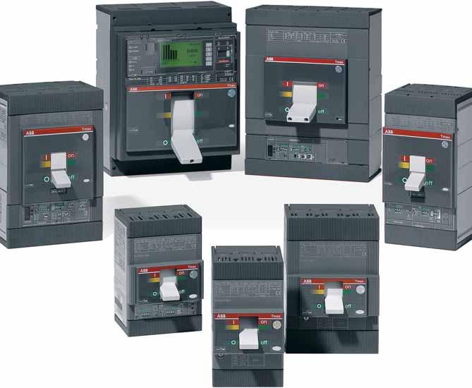
3 Moulded case circuit-breakers Tmax - General The moulded case circuit-breakers Tmax family is now available as a complete range up to 1600 A. All the circuit-breakers, both three-pole and four-pole, are available in the fi xed version; the sizes T2, T3, T4 and T5 in the plug-in version and T4, T5, T6 and T7 in the withdrawable one as well. With the same frame size, the circuit-breakers in the Tmax family, are available with different breaking capacities and different rated uninterrupted currents. 1SDC210014F0001 7/2

4 Moulded case circuit-breakers Tmax - General The electric arc interruption system used on the Tmax circuit-breakers allows the short-circuit currents of very high value to be interrupted extremely rapidly. The considerable opening speed of the contacts, the dynamic blasting action carried out by the magnetic fi eld and the structure of the arcing chamber contribute to extinguishing the arc in the shortest possible time, notably limiting the value of the specifi c let-through energy I 2 t and the current peak. 1SDC210015F0001 MCCBs 7/3
![Overview of the Tmax family Circuit-breakers for AC-DC distribution T1 1p T1 Iu [A] 160 160 In [A] 16 160 16](/docs-images/73/68302195/images/5-0.jpg "160 Poles [Nr] 1 3/4 Ue [V] (AC) 50-60 Hz 240 690 [V] (DC) 125 500 Icu (380-415 V AC) [ka] B 25* (220/230 V AC)")
![16 [ka] C 25 [ka] N 36 [ka] S [ka] H [ka] L [ka] V Circuit-breakers for zone selectivity Iu [A] Poles [Nr] Ue](/docs-images/73/68302195/images/5-1.jpg "[V] (AC) 50-60 Hz EFDP zone selectivity ZS zone selectivity Circuit-breakers for motor protection Iu [A] Poles")
![[Nr] Ue [V] (AC) 50-60 Hz Magnetic only trip unit, IEC 60947-2 PR221DS-I trip unit, IEC 60947-2 PR222MP trip](/docs-images/73/68302195/images/5-2.jpg "unit, IEC 60947-4-1 PR231/P-I trip unit, IEC 60947-2 Circuit-breakers for use up to 1150 V AC and 1000 V DC Iu")
![[A] Poles [Nr] Icu max [KA] 1000 V AC [KA] 1150 V AC [KA] 1000 V DC 4 poles in series Switch-disconnectors T1D](/docs-images/73/68302195/images/5-3.jpg "Ith [A] 160 Ie [A] 125 Poles [Nr] 3/4 Ue [V] (AC) 50-60 Hz 690 [V] (DC) 500 Icm [ka] 2.")
![8 Icw [ka] 2 * For In 16 A and In 20 A: Icu @ 220/230 V AC = 16 ka Note: The moulded case circuit-breakers are](/docs-images/73/68302195/images/5-4.jpg "also available in the versions according to UL Standards (see catalogue Moulded case circuit-breakers - UL 489")
5 Overview of the Tmax family Circuit-breakers for AC-DC distribution T1 1p T1 Iu [A] In [A] Poles [Nr] 1 3/4 Ue [V] (AC) Hz [V] (DC) Icu ( V AC) [ka] B 25* (220/230 V AC) 16 [ka] C 25 [ka] N 36 [ka] S [ka] H [ka] L [ka] V Circuit-breakers for zone selectivity Iu [A] Poles [Nr] Ue [V] (AC) Hz EFDP zone selectivity ZS zone selectivity Circuit-breakers for motor protection Iu [A] Poles [Nr] Ue [V] (AC) Hz Magnetic only trip unit, IEC PR221DS-I trip unit, IEC PR222MP trip unit, IEC PR231/P-I trip unit, IEC Circuit-breakers for use up to 1150 V AC and 1000 V DC Iu [A] Poles [Nr] Icu max [KA] 1000 V AC [KA] 1150 V AC [KA] 1000 V DC 4 poles in series Switch-disconnectors T1D Ith [A] 160 Ie [A] 125 Poles [Nr] 3/4 Ue [V] (AC) Hz 690 [V] (DC) 500 Icm [ka] 2.8 Icw [ka] 2 * For In 16 A and In 20 A: 220/230 V AC = 16 ka Note: The moulded case circuit-breakers are also available in the versions according to UL Standards (see catalogue Moulded case circuit-breakers - UL 489 and CSA C22.2 Standard ). 7/4
6 T2 T3 T4 T5 T6 T / / /800/ /1000/1250/ /4 3/4 3/4 3/4 3/4 3/ T4 T5 T6 T7 250/ / / /1000/1250/1600 3/4 3/4 3/4 3/ T2 T3 T4 T5 T6 T / / /1000/ MCCBs T4 T5 T / /800 3/4 3/4 3/ T3D T4D T5D T6D T7D / / /800/ /1250/ / / /800/ /1250/1600 3/4 3/4 3/4 3/4 3/ /5
7 Moulded case circuit-breakers Tmax - Power distribution circuit-breakers Technical Data 7/6 Tmax T1 1P Tmax T1 Tmax T2 Rated uninterrupted current, Iu [A] Poles [Nr] 1 3/4 3/4 Rated service current, Ue (AC) Hz [V] (DC) [V] Rated impulse withstand voltage, Uimp [kv] Rated insulation voltage, Ui [V] Test voltage at industrial frequency for 1 min. [V] Rated ultimate short-circuit breaking capacity, Icu B B C N N S H L (AC) Hz 220/230 V [ka] 25* (AC) Hz 380/415 V [ka] (AC) Hz 440 V [ka] (AC) Hz 500 V [ka] (AC) Hz 690 V [ka] (DC) 250 V - 2 poles in series [ka] 25 (at 125 V) (DC) 250 V - 3 poles in series [ka] (DC) 500 V - 2 poles in series [ka] (DC) 500 V - 3 poles in series [ka] (DC) 750 V - 3 poles in series [ka] Rated service short-circuit breaking capacity, Ics (AC) Hz 220/230 V [%Icu] 75% 100% 75% 75% 100% 100% 100% 100% (AC) Hz 380/415 V [%Icu] 100% 100% 75% 100% 100% 100% 75% (70 ka) (AC) Hz 440 V [%Icu] 100% 75% 50% 100% 100% 100% 75% (AC) Hz 500 V [%Icu] 100% 75% 50% 100% 100% 100% 75% (AC) Hz 690 V [%Icu] 100% 75% 50% 100% 100% 100% 75% Rated short-circuit making capacity, Icm (AC) Hz 220/230 V [ka] (AC) Hz 380/415 V [ka] (AC) Hz 440 V [ka] (AC) Hz 500 V [ka] (AC) Hz 690 V [ka] Opening time (415 V) [ms] Utilisation category (IEC ) A A A Reference Standard IEC IEC IEC Isolation behaviour Trip units: thermomagnetic T fi xed, M fi xed TMF T adjustable, M fi xed TMD T adjustable, M adjustable (5 10 x In) TMA T adjustable, M fi xed (3 x In) TMG (8) T adjustable, M adjustable (2.5 5 x In) TMG magnetic only MA (MF up to In 12.5 A) electronic PR221DS PR222DS PR223DS PR231/P PR232/P PR331/P PR332/P Interchangeability Versions F F F-P Terminals fi xed FC Cu FC Cu-EF-FC CuAl-HR F-FC Cu-FC CuAl-EF-ES-R plug-in F-FC Cu-FC CuAl-EF-ES-R withdrawable Fixing on DIN rail DIN EN DIN EN Mechanical life [No. operations] [No. Hourly operations] Electrical 415 V AC [No. operations] [No. Hourly operations] Basic dimensions - fi xed version 3 poles W [mm] 25.4 (1 pole) poles W [mm] D [mm] H [mm] Weight fi xed 3/4 poles [kg] 0.4 (1 pole) 0.9/ /1.5 plug-in 3/4 poles [kg] 1.5/1.9 withdrawable 3/4 poles [kg] TERMINAL CAPTION F = Front EF = Front extended ES = Front extended spread FC Cu = Front for copper cables FC CuAl = Front for copper-aluminium cables R = Rear orientated HR = Rear fl at horizontal VR = Rear fl at vertical HR/VR = Rear fl at orientated MC = Multicable F = fi xed circuit-breakers P = plug-in circuit-breakers W = withdrawable circuit-breakers (*) The breaking capacity for settings In=16 A and In=20 A is 16 ka
8 Tmax T3 Tmax T4 Tmax T5 Tmax T6 Tmax T / / /800/ /1000/1250/1600 3/4 3/4 3/4 3/4 3/ N S N S H L V N S H L V N S H L S H L V (6) % 50% 100% 100% 100% 100% 100% 100% 100% 100% 100% 100% 100% 100% 100% 75% 100% 100% 100% 100% 75% 50% (27 ka) 100% 100% 100% 100% 100% 100% 100% 100% 100% 100% 100% 100% 100% 75% 100% 100% 100% 100% 75% 50% 100% 100% 100% 100% 100% 100% 100% 100% 100% 100% 100% 100% 100% 75% 100% 100% 100% 100% 75% 50% 100% 100% 100% 100% 100% 100% 100% 100% 100% (1) 100% (2) 100% 100% 100% 75% 100% 100% 75% 100% 75% 50% 100% 100% 100% 100% 100% 100% 100% 100% (1) 100% (2) 100% (2) 75% 75% 75% 75% 100% 75% 75% 75% A A B (400 A) (3) - A (630 A) B (630A - 800A) (5) - A (1000A) B (7) IEC IEC IEC IEC IEC (up to 50 A) (up to 250 A) (up to 500 A) (up to 800 A) (4) (up to 500 A) F-P F-P-W F-P-W F-W (4) F-W F-FC Cu-FC Cu Al-EF-ES-R F-FC Cu-FC CuAl-EF-ES-R-MC F-FC CuAl-EF-ES-R-RC F-FC CuAl-EF-ES-R F-EF-ES-FC CuAl-HR/VR F-FC Cu-FC Cu Al-EF-ES-R EF-ES-HR-VR-FC Cu-FC CuAl EF-ES-HR-VR-FC Cu-FC CuAl EF-ES-HR-VR-FC Cu-FC CuAl EF-ES-HR-VR-FC Cu-FC CuAl EF-HR-VR F-HR/VR DIN EN (250 A) (320 A) 7000 (400 A) (630 A) 7000 (630A) (800A) (1000A) 2000 (S, H, L versions) / 3000 (V version) (manual) /178 (motorizable) /2 2.35/ / /12 9.7/12.5 (manual) - 11/14 (motorizable) 2.7/ / / / / / /39.6 (manual) - 32/42.6(motorizable) (1) 75% for T5 630 (2) 50% for T5 630 (3) Icw = 5 ka (4) W version is not available on T A (5) Icw = 7.6 ka (630 A) - 10 ka (800 A) (6) Only for T7 800/1000/1250 A (7) Icw = 20 ka (S,H,L versions) - 15 ka (V version) (8) For availability, please ask ABB Notes: In the plug-in version of T2, T3 and T5 630 and in the withdrawable version of T5 630 the maximum rated current available is derated by 10% at 40 C MCCBs 7/7
9 Moulded case circuit-breakers Tmax - Power distribution circuit-breakers Technical Data The series of Tmax moulded-case circuit-breakers - complying with the IEC Standard - is divided into seven basic sizes, with an application range from 1 A to 1600 A and breaking capacities from 16 ka to 200 ka (at 380/415 V AC). For protection of alternating current networks, the following are available: T1B 1p circuit-breaker, equipped with TMF thermomagnetic trip units with fi xed thermal and magnetic threshold (I 3 = 10 x In); T1, T2, T3 and T4 (up to 50 A) circuit-breakers equipped with TMD thermomagnetic trip units with adjustable thermal threshold (I 1 = x In) and fi xed magnetic threshold (I 3 = 10 x In); T2, T3 and T5 circuit-breakers, fi tted with TMG trip units for long cables and generator protection with adjustable thermal threshold (I 1 = x In) and fi xed magnetic threshold (I 3 = 3 x In) for T2 and T3 and adjustable magnetic threshold (I 3 = x In) for T5; T4, T5 and T6 circuit-breakers with TMA thermomagnetic trip units with adjustable thermal threshold (I 1 = x In) and adjustable magnetic threshold (I 3 = 5 10 x In); T2 with PR221DS electronic trip unit; T4, T5 and T6 with PR221DS, PR222DS/P, PR222DS/PD and PR223DS electronic trip units; the T7 circuit-breaker, which completes the Tmax family up to 1600 A, fi tted with PR231/P, PR232/P, PR331/P and PR332/P electronic trip units. The T7 circuit-breaker is available in the two versions: with manual operating mechanism or motorizable with stored energy operating mechanism (*). The fi eld of application in alternating current of the Tmax series varies from 1 A to 1600 A with voltages up to 690 V. The Tmax T1, T2, T3, T4, T5 and T6 circuit-breakers equipped with TMF, TMD and TMA thermomagnetic trip units can also be used in direct current plants, with a range of application from 1 A to 800 A and a minimum operating voltage of 24 V DC, according to the appropriate connection diagrams. The three-pole T2, T3 and T4 circuit-breakers can also be fi tted with MF and MA adjustable magnetic only trip units, both for applications in alternating current and in direct current, in particular for motor protection. (*) For motorisation, the T7 circuit-breaker with stored energy operating mechanism must be ordered, complete with geared motor for automatic spring charging, opening coil and closing coil. Interchangeability The Tmax T4, T5 and T6 circuit-breakers can be equipped either with TMF, TMD, TMG or TMA thermomagnetic trip units, MA magnetic only trip units or PR221DS, PR222DS/P, PR222DS/PD, PR222MP and PR223DS electronic trip units. Similarly, Tmax T7 can also mount the latest generation PR231/P, PR232/P, PR331/P (1) and PR332/P (1) electronic trip units. Trip units Circuit-breakers TMD TMA TMG In [A] T4 250 T4 320 T5 400 T5 630 T6 630 T6 800 T T7 800 T T T = Complete circuit-breaker already coded = Circuit-breaker to be assembled (1) If ordered loose PR331/P and PR332/P must be completed with the trip unit adapters 7/8
10 Moulded case circuit-breakers Tmax - Power distribution circuit-breakers Technical Data Range of application of the circuit-breakers in alternating current and in direct current AC Trip unit Range [A] T1 1p 160 TMF T1 160 TMD T2 160 TMD TMG MF/MA PR221DS T3 250 TMG TMD MA T4 250/320 TMD TMA MA PR221DS PR222DS/P-PR222DS/PD PR223DS T5 400/630 TMG TMA PR221DS PR222DS/P-PR222DS/PD PR223DS T6 630/800/1000 TMA PR221DS PR222DS/P-PR222DS/PD PR223DS T7 800/1000/1250/1600 PR231/P-PR232/P PR331/P-PR332/P DC T1 1p 160 TMF T1 160 TMD T2 160 TMD MF/MA T3 250 TMD/TMG MA T4 250/320 TMD TMA MA T5 400/630 TMA/TMG T6 630/800/1000 TMA MF = magnetic only trip unit with fi xed magnetic thresholds MA = magnetic only trip unit with adjustable magnetic thresholds TMF = thermomagnetic trip unit with fi xe thermal and magnetic thresholds TMD = thermomagnetic trip unit with adjustable thermal and fi xedmagnetic thresholds TMA = thermomagnetic trip unit with adjustable thermal and magnetic thresholds TMG = thermomagnetic trip unit for generator protection PR22_, PR23_, PR33_ = electronic trip units Thanks to their simplicity of assembly, the end customer can change the type of trip unit extremely rapidly, according to their own requirements and needs: in this case, correct assembly is the customer s responsibility. Above all, this means into increased fl exibility of use of the circuit-breakers with considerable savings in terms of costs thanks to better rationalisation of stock management. MCCBs MA PR221DS-PR222DS/P-PR222DS/PD-PR223DS PR231/P (2) -PR232/P-PR331/P-PR332/P (2) Interchangeability of PR231/P can be requested by means of the dedicated ordering code 1SDA063140R1. 7/9

.")
11 Moulded case circuit-breakers Tmax - Power distribution circuit-breakers Thermomagnetic trip units The Tmax T1 1p, T1, T2, T3, T4, T5 and T6 circuit-breakers can be fi tted with thermomagnetic trip units and are used in protection of alternating and direct current networks with a range of use from 1.6 A to 800 A. They allow the protection against overload with a thermal device (with fi xed threshold for T1 1p and adjustable threshold for T1, T2, T3, T4, T5 and T6) realised using the bimetal technique, and protection against short-circuit with a magnetic device (with fi xed threshold for T1, T2 and T3 and T4 up to 50 A and adjustable threshold for T4, T5 and T6). The four-pole circuit-breakers are always supplied with the neutral protected by the trip unit and with protection of the neutral at 100% of the phase setting for settings up to 100 A. For higher settings, the protection of the neutral is at 50% of the phase setting unless the protection of the neutral at 100% of In is required. Furthermore, for Tmax T2, T3 and T5, the TMG thermomagnetic trip units with low magnetic trip threshold are available. For T2 and T3 the trip unit has adjustable thermal threshold (I 1 = x In) and fi xed magnetic threshold (I 3 = 3 x In), whereas for T5 the trip unit has adjustable thermal threshold (I 1 = x In) and adjustable magnetic threshold (I 3 = x In). The thermomagnetic trip units can be used to protect long cables and for generator protection, both in direct current and in alternating current. Thermomagnetic trip units TMD e TMG (for T1, T2 and T3) Thermal threshold Adjustable from 0.7 to 1 x In 1SDC210B03F0001 1SDC210B02F0001 Thermal threshold Adjustable from 0.7 to 1 x In TMD = thermomagnetic trip unit with adjustable thermal threshold (I 1 = x In) and fi xed magnetic threshold (I 3 = 10 x In). TMG = thermomagnetic trip unit with adjustable thermal threshold (I 1 = x In) and fi xed magnetic threshold (I 3 = 3 x In). Thermomagnetic trip units TMD/TMA and TMG (for T4, T5 and T6) Thermal threshold Adjustable Thermal threshold Adjustable from 0.7 to 1 x In 1SDC210B04F0001 TMA = thermomagnetic trip unit with adjustable thermal threshold (I 1 = x In) and adjustable magnetic threshold (I 3 = 5 10 x In) TMG (for T5) = thermomagnetic trip unit with adjustable thermal threshold (I 1 = x In) and adjustable magnetic threshold (I 3 = x In) 7/10
12 Moulded case circuit-breakers Tmax - Power distribution circuit-breakers Electronic trip units The Tmax T2, T4, T5, T6 and T7 circuit-breakers, for use in alternating current, can be equipped with overcurrent releases constructed using electronic technology. This allows protection functions to be obtained which guarantee high reliability, tripping precision and insensitivity to temperature and to the electromagnetic components in conformity with the standards on the matter. The power supply needed for correct operation is supplied directly by the current sensors of the release, and tripping is always guaranteed, even under single-phase load conditions and in correspondence with the minimum setting. Characteristics of the Tmax electronic trip units Operating temperature -25 C +70 C Relative humidity 98% Self-supply 0.2 x In (single phase) Auxiliary power supply (where applicable) 24 V DC Operating frequency Hz Electromagnetic compatibility (LF and HF) IEC Annex F For Tmax T2, T4, T5 and T6 the protection trip unit consists of: 3 or 4 current sensors (current transformers) external current sensors (e.g. for the external neutral), when available a trip unit a trip coil (for T2 housed in the right slot, for T4, T5 and T6 integrated in the electronic trip unit). For Tmax T7 the protection trip unit consists of: 3 or 4 current sensors (Rogowski coils and current transformers) external current sensors (e.g. for the external neutral) interchangeable rating plug a trip unit a trip coil housed in the body of the circuit-breaker. Rating plugs Circuit-breaker CS Rated current I u T In [A] The current sensors supply the electronic trip unit with the energy needed for correct operation of the trip unit and the signal needed to detect the current. The current sensors are available with rated primary current as shown in the table. MCCBs Current sensors In [A] PR221DS T2 T4 T5 T6 PR222DS/P, PR222DS/PD, T4 PR223DS T5 T6 PR231/P, PR232/P, PR331/P, PR332/P T7 When a protection function trips, the circuit-breaker opens by means of the trip coil, which changes over a contact (AUX-SA, supplied on request, see chapter Accessories at page 3/20 and following) to signal trip unit tripped. Signalling reset is of mechanical type and takes place with resetting of the circuit-breaker. 7/11
13 Moulded case circuit-breakers Tmax - Power distribution circuit-breakers Electronic trip units Basic protection functions (L) Protection against overload This protection function trips when there is an overload with inverse long-time delay trip according to the IEC Standard (I 2 t=k). The protection cannot be excluded. (S) Protection against short-circuit with time delay This protection function trips when there is a short-circuit, with long inverse time-delay trip (I 2 t=k ON) or a constant trip time (I 2 t=k OFF). The protection can be excluded. (I) Instantaneous protection against short-circuit This protection function trips instantaneously in case of a short-circuit. The protection can be excluded. (G) Protection against earth fault The protection against earth fault trips when the vectorial sum of the currents passing through the current sensors exceeds the set threshold value, with long inverse time-delay trip (I 2 t=k ON) or a constant trip time (I 2 t=k OFF). The protection can be excluded. Advanced protection functions The PR332/P trip unit makes it possible to carry out highly developed protection against the most varied types of fault. In fact, it adds the following advanced protection functions to the basic protection functions. IEC (L) Protection against overload (IEC ) This protection trips in case of an overload with inverse long-time delay according to IEC Standard, for the coordination with fuses and MV protections. The protection can be excluded. (U) Protection against unbalanced phase The protection function against unbalanced phase U can be used in those cases where a particularly precise control is needed regarding missing and/or unbalance of the phase currents. The trip time is instantaneous. The protection can be excluded. OT Rc (OT) Protection against overtemperature The protection against overtemperature trips instantaneously when the temperature inside the trip unit exceeds 85 C, in order to prevent any temporary or continual malfunction of the microprocessor. The protection cannot be excluded. (Rc) Protection against residual current (1) This integrated protection is based on current measurements made by an external toroid and is alternative to protection against earth fault G. The protection can be excluded. ZS (ZS) Zone selectivity (2) ZS zone selectivity is an advanced method for carrying out coordination of the protections in order to reduce the trip times of the protection closest to the fault in relation to the time foreseen by time selectivity. Zone selectivity can be applied to the protection functions S and G, with constant time-delay trip. The protection can be excluded. UV OV RV (UV, OV, RV) Protections against voltage The three protections trip with a constant time-delay in the case of undervoltage, overvoltage and residual voltage respectively. The latter allows to detect interruptions of the neutral (or of the earthing conductor in systems with earthed neutral) and faults which cause movement of the star centre in systems with isolated neutral (e.g. large earth faults) to be identifi ed. Movement of the star centre is calculated by vectorially summing the phase voltages. The protections can be excluded. RP (RP) Protection against reversal of power The protection against reversal power causes tripping of the breaker, with constant time-delay trip, when the fl ow of power reverses sign and exceeds, as an absolute value, the set threshold. It is particularly suitable for protection of large machines such as generators. The protection can be excluded. UF OF (UF, OF) Protections of frequency The two protections detect the variation in network frequency above or below the adjustable thresholds, opening the circuit-breaker, with constant time-delay trip. The protection can be excluded. 7/12 (1) It is not suitable for human protection. (2) For further information about zone selectivity, please see the section: Circuit-breakers for zone selectivity.
14 Moulded case circuit-breakers Tmax - Power distribution circuit-breakers Electronic trip units Electronic trip units for power distribution SACE PR221DS PR221DS PR221DS Protection functions / SACE PR222DS/P PR222DS/P PR222DS/P Protection functions SACE PR222DS/PD MCCBs PR222DS/PD PR222DS/PD Protection functions SACE PR223DS PR223DS Protection functions 7/13
15 Moulded case circuit-breakers Tmax - Power distribution circuit-breakers Electronic trip units SACE PR231/P PR231/P PR231/P Protection functions / SACE PR232/P PR232/P Protection functions SACE PR331/P PR331/P Protection functions SACE PR332/P Protection functions Advanced protection function (*) PR332/P PR332/P PR332/P PR332/P Rc (***) (***) (***) (***) OT OT OT OT Opt. (**) UV OV RV RP UF OF UV OV RV RP UF OF UV OV RV RP UF OF UV OV RV RP UF OF (1) In alternative to Rc (with external toroid). (*) For all versions. (**) Available with PR330/V. Measurement module. (***) According to IEC /14
16 Moulded case circuit-breakers Tmax - Power distribution circuit-breakers Ordering details - Reading information Abbreviations used to describe the apparatus F = Front terminals EF = Front extended terminals ES = Front extended spread terminals FC Cu = Front terminals for copper cables FC CuAl = Front terminals for Cu/Al cables FC CuAl = Front terminals for Cu/Al cables (housed externally) RC CuAl = Rear terminals for Cu/Al cables R = Rear terminals MC = Multi-cable terminals HR for RC221/222 = Rear flat horizontal terminals HR = Rear flat horizontal terminals VR = Rear flat vertical terminals HR/VR = Rear flat terminals I 3 In Magnetic trip current [A] Rated current of the thermomagnetic trip unit [A] Iu Icu Rated uninterrupted current of the circuit-breaker [A] Rated ultimate short-circuit breaking capacity [A] N= 50% N= 100% Protection of the neutral at 50% or at 100% of that of the phases [A] MCCBs Icw Rated short-time withstand current for 1s TMF TMD = Thermomagnetic trip unit with fixed thermal and magnetic threshold = Thermomagnetic trip unit with adjustable thermal and fixed magnetic threshold TMA TMG = Thermomagnetic trip unit with adjustable thermal and magnetic threshold = Thermomagnetic trip unit for generator protection MF MA = Fixed magnetic only trip units = Adjustable magnetic only trip units PR22_ = Electronic trip units PR23_ = Electronic trip units PR33_ = Electronic trip units 7/15
17 Moulded case circuit-breakers Tmax - Power distribution circuit-breakers Ordering details - Instructions for ordering Ordering Tmax circuit-breakers fi tted with the accessories indicated in the catalogue means that these must be indicated by means of the relative sales codes expressly associated with the circuitbreaker code. The following examples are of particular importance for correctly loading orders for Tmax circuit-breakers fi tted with accessories. 1) Terminal Kit for fixed circuit-breaker To fi t the circuit-breaker with different terminal accessories than those supplied on the basic circuitbreaker, it is possible to ask for complete kits (6 or 8 pieces) or half kits (3 or 4 pieces). For conversion of a complete circuit-breaker, it is necessary to specify the complete terminal kit. In the case of a mixed solution, the fi rst code specifi ed indicates the terminals to be mounted at the top, the second indicates the terminals to be mounted at the bottom. On the other hand, when only 3 or 4 pieces are requested, it is important to specify expressly whether the half kit is to be mounted at the top (*) rather than at the bottom (**). a) Tmax T3N 250 with top FC Cu and bottom F terminals 1SDA...R1 T3N 250 TMD 63 3p F F /2 KIT FC Cu T3 3p (*) c) Tmax T3N 250 with top F and bottom FC Cu terminals 1SDA...R1 T3N 250 TMD 63 3p F F /2 KIT FC Cu T3 3p (**) d) Tmax T3N 250 with FC Cu terminals 1SDA...R1 T3N 250 TMD 63 3p F F KIT FC Cu T3 3p e) Tmax T3N 250 with top ES and FC Cu bottom terminals 1SDA...R1 T3N 250 TMD 63 3p F F /2 KIT ES T3 3p (*) /2 KIT FC Cu T3 3p (**) ) T2-T3 electrical accessories on moving part of plug-in circuit-breaker Fitting the moving parts of plug-in T2-T3 circuit-breakers with SOR, UVR and AUX and with SOR-C, UVR-C and AUX-C accessories always requires the appropriate plug-socket indicated in the catalogue. a) Tmax T2N 160 moving part of plug-in circuit-breakers with auxiliary contacts 1SDA...R1 T2N 160 F F TMD 10 4p Kit P MP T2 4p AUX 1Q 1SY 250 V AC/DC socket-plug connectors 6 pole b) Tmax T2N 160 moving part of plug-in circuit-breakers with auxiliary contacts and opening coil 1SDA...R1 T2N 160 F F TMD 10 4p Kit P MP T2 4p AUX 3Q 1SY 250 V AC/DC SOR V AC / V DC socket-plug connectors 6 pole socket-plug connectors 3 pole /16
18 Moulded case circuit-breakers Tmax - Power distribution circuit-breakers Ordering details - Instructions for ordering 3) T4-T5 electrical accessories on moving part of plug-in circuit-breaker Fitting the moving parts of plug-in T4-T5 circuit-breakers with SOR, UVR and AUX accessories always requires the appropriate plug-sockets, i.e. in the case of cabled electrical accessories SOR-C, UVR-C, AUX-C, MOE, MOE-E and AUE, the ADP adapters indicated in the catalogue. a) Tmax T4H 250 moving part of plug-in circuit-breakers with auxiliary contacts 1SDA...R1 T4L 250 F F P221DS-LS/I 100 4p Kit P MP T4 4p AUX 3Q 1SY 250 V AC/DC socket-plug connectors 12 pole b) Tmax T4H 250 moving part of plug-in circuit-breakers with cabled auxiliary contacts 1SDA...R1 T4L 250 F F P221DS-LS/I 100 4p Kit P MP T4 4p AUX-C 3Q 1SY 250 V AC/DC ADP 12 pin adapter c) Tmax T5H 630 moving part of plug-in circuit-breaker with SOR-C, MOE and AUX-C 1SDA...R1 T4L 250 F F P221DS-LS/I 100 4p Kit P MP T4 4p SOR-C V AC V DC MOE T4-T V AC/DC ADP 10 pin adapter AU-C 1Q 1SY 250 V AC/DC ADP 6 pin adapter ) T4-T5 electrical accessories on moving part of withdrawable circuit-breaker Fitting the moving parts of T4-T5 withdrawable circuit-breakers can only take place using electrical accessories in the cabled version, i.e. SOR-C, UVR-C, AUX-C, MOE, MOE-E and AUE with ADP adapter. a) Tmax T5V 630 moving part of withdrawable circuit-breaker with UVR-C and MOE 1SDA...R1 T5V 630 F F TMA 500 4p N=100% Kit W MP T p UVR-C V AC/DC MOE T4-T5 24 V DC ADP 10 pin adapter MCCBs b) Tmax T4S 250 moving part of withdrawable circuit-breaker SOR-C, RHE and AUE 1SDA...R1 T4S 250 PR221DS-LS/I 100 4p F F KIT W MP T4 4p RHE normal for withdrawable circuit-breaker AUE 2 early contacts SOR-C V AC / V DC ADP 10 pin adapter /17
19 Moulded case circuit-breakers Tmax - Power distribution circuit-breakers Ordering details - Instructions for ordering 5) Rear mechanical interlock T3 The rear MIR interlock for T3 allows all the accessories to be used. To be able to take the circuitbreakers and/or the fi xed parts mounted directly on the interlocking plate, it is necessary to use code 1SDA050093R1 to be specifi ed regarding the second circuit-breaker (or fi xed part) to be interlocked. Horizontal mechanical interlock made between two T3S 250 1SDA...R1 POS1 T3S 250 TMD 200 4p FF MIR-H rear mechanical interlock for T POS2 T3S 250 TMD 160 4p FF Extra code for circuit-breaker/fi xed part mounted on the interlock ) T4-T5 mechanical interlock The rear interlock for T4 and T5, consisting of the MIR-HB or MIR-VB frame unit and the MIR-P plates, allows use of all the front accessories compatible with the circuit-breakers used. To be able to receive the circuit-breakers mounted directly on the interlock plate, code 1SDA050093R1 must be specifi ed regarding the second circuit-breaker (or fi xed part) which is to be interlocked. Horizontal mechanical interlock made between T4H 320 and T5L 630 1SDA...R1 POS1 T4H 320 PR221DS-LS/I 320 4p F F MIR-HB horizontal interlock frame unit MIR-P plates for type B interlock POS2 T5L 630 PR221DS-LS/I 630 4p F F Code for circuit-breakers mounted on the plate ) PR222DS/PD T4-T5 The T4 and T5 circuit-breakers can be fi tted with the PR222DS/PD electronic trip unit, with communication and integrated control functions, using the special extracodes indicated in the catalogue. The circuit-breakers fi tted with the PR222DS/PD trip unit can only have the AUX-E electronic version of auxiliary contacts mounted, to communicate the state of the circuit-breaker to the PR222DS/PD, and the MOE-E dedicated stored energy operating mechanism, to remotely control circuit-breaker opening and closing. a) T4V 250 with dialogue, auxiliary contacts and motor operator 1SDA...R1 T4V 250 PR222DS/PD-LSIG 250 3p F F Extracode - Dialogue unit for LSIG AUX-E-C 1Q 1SY MOE-E T4-T5 380 V AC X3 for PR222DS/P/PD T4-T5 F b) T4V 250 moving part of withdrawable circuit-breaker with dialogue, auxiliary contacts and motor operator 1SDA...R1 T4V 250 PR222DS/PD-LSIG 250 3p F F Extracode - Dialogue unit for LSIG Kit W MP T AUX-E-C 1Q 1SY ADP - 6 pin adapter MOE-E T4-T5 380 V AC ADP 10 pin adapter X3 for PR222DS/P/PD T4-T5 P/W /18
20 Moulded case circuit-breakers Tmax - Power distribution circuit-breakers Ordering details - Instructions for ordering 8) Rating plug for Tmax T7 Thanks to the extra codes for the Tmax T7 rating plug, it is possible to ask for a Tmax T7 circuitbreaker with lower rated current than the standard versions. T7S 400 with PR332/P LSIG lever operating mechanism 1SDA...R1 T7S 800 PR332/P-LSIG In=800 3p F F Extra code for 400 A rating plug ) Sliding contacts for Tmax T7 in version withdrawable The electrical accessories of Tmax T7 in the withdrawable version must be fi tted with suitable sliding contacts for the moving part and for the fi xed part. (a) T7S 1000 PR231/P with lever operating mechanism in withdrawable version, opening coil and auxiliary contacts 1SDA...R1 POS1 T7S 1000 PR231/P LS/I In=1000A 3p F F Kit MP T7-T7M W 3p SOR V AC/DC Opening coil AUX 1Q + 1SY Auxiliary contacts Right PM sliding block POS2 Fixed part for withdrawable T Right PF sliding block (b) T7S 1250 PR332/P with lever operating mechanism in withdrawable version and undervoltage release 1SDA...R1 POS1 T7S 1250 PR332/P LSIG In=1250A 3p F F Kit MP T7-T7M W 3p UVR V AC/DC Undervoltage release Right PM sliding block Central PM sliding block POS2 Fixed part for withdrawable T Right PF sliding block Central PF sliding block MCCBs 10) Interchangeability of the PR231/P trip unit for Tmax T7 Interchangeable T7S 800 PR231/P, with lever operating mechanism T7S 800 PR231/P LS/I In=800 A 4p F F Extra code for PR231/P interchangeability ) Motorisation for Tmax T7 For Tmax T7 motorisation, the circuit-breaker in T7M version which can be motorised, must be fi tted with spring charging geared motor, opening coil and closing coil. Motorised T7S 1000 PR232/P T7S 1000 M PR232/P LSI In=1000 A 4p F F V AC/DC Spring charging geared motor SOR V AC/DC Opening coil V AC/DC Closing coil /19
21 Moulded case circuit-breakers Tmax - Power distribution circuit-breakers Ordering details - T1 T1 1p 160 Fixed (F) 1 Pole - Iu (40 C) = 160 A - Front terminals for copper cables (FC Cu) 1SDC210180F0004 In I 3 1SDA... R1 B Thermomagnetic trip unit with fixed thresholds - TMF Icu (230 V) 25 ka T1 160 Fixed (F) - Iu (40 C) = 160 A - Front terminals for copper cables (FC Cu) 1SDC210302F0004 In I 3 1SDA... R1 B C N Thermomagnetic trip unit - TMD Icu (415 V) 16 ka 25 ka 36 ka T1 160 Fixed (F) - Iu (40 C) = 160 A - Front terminals for copper cables (FC Cu) In I 3 1SDA... R1 B C N Thermomagnetic trip unit - TMD Icu (415 V) 16 ka 25 ka 36 ka N=50% N=100% see Abbreviation caption page 7/15 7/20
22 Moulded case circuit-breakers Tmax - Power distribution circuit-breakers Ordering details - T2 1SDC210303F0004 T2 160 Fixed (F) - Iu (40 C) = 160 A - Front terminals (F) In I 3 1SDA... R1 N S H L Thermomagnetic trip unit - TMD Icu (415 V) 36 ka 50 ka 70 ka 85 ka In I 3 1SDA... R1 N S Thermomagnetic trip unit for generator protection - TMG (1) Icu (415 V) 36 ka 50 ka MCCBs In 1SDA... R1 N S H L Electronic trip unit Icu (415 V) 36 ka 50 ka 70 ka 85 ka PR221DS-LS/I PR221DS-LS/I PR221DS-LS/I PR221DS-LS/I PR221DS-LS/I PR221DS-I PR221DS-I PR221DS-I PR221DS-I PR221DS-I Note: The trip coil of the T2 circuit-breaker with PR221DS electronic trip unit is housed in the right slot. For T2 with PR221DS the following groups of auxiliary contacts are available: 1SDA053704R1 Aux-C 1S51-1Q-1SY 1SDA055504R1 Aux-C 2Q-1SY (1) For availability, please ask ABB see Abbreviation caption page 7/15 7/21
23 Moulded case circuit-breakers Tmax - Power distribution circuit-breakers Ordering details - T2 1SDC210303F0004 T2 160 Fixed (F) - Iu (40 C) = 160 A - Front terminals (F) In I 3 1SDA... R1 N S H L Thermomagnetic trip unit - TMD Icu (415 V) 36 ka 50 ka 70 ka 85 ka N=50% N=50% N=100% N=100% In I 3 1SDA... R1 N S Thermomagnetic trip unit for generator protection - TMG (1) Icu (415 V) 36 ka 50 ka In 1SDA... R1 N S H L Electronic trip unit Icu (415 V) 36 ka 50 ka 70 ka 85 ka PR221DS-LS/I PR221DS-LS/I PR221DS-LS/I PR221DS-LS/I PR221DS-LS/I 160 N=50% PR221DS-LS/I 160 N=100% PR221DS-I PR221DS-I PR221DS-I PR221DS-I PR221DS-I 160 N=50% PR221DS-I 160 N=100% Note: The trip coil of the T2 circuit-breaker with PR221DS electronic trip unit is housed in the right slot. For T2 with PR221DS the following groups of auxiliary contacts are available: 1SDA053704R1 Aux-C 1S51-1Q-1SY 1SDA055504R1 Aux-C 2Q-1SY (1) For availability, please ask ABB see Abbreviation caption page 7/15 7/22
24 Moulded case circuit-breakers Tmax - Power distribution circuit-breakers Ordering details - T3 T3 250 Fixed (F) - Iu (40 C) = 250 A - Front terminals (F) 1SDC210304F0004 In I 3 1SDA... R1 N S Thermomagnetic trip unit - TMD Icu (415 V) 36 ka 50 ka In I 3 1SDA... R1 N S Thermomagnetic trip unit for generator protection - TMG Icu (415 V) 36 ka 50 ka T3 250 Fixed (F) - Iu (40 C) = 250 A - Front terminals (F) In I 3 1SDA... R1 N S Thermomagnetic trip unit - TMD Icu (415 V) 36 ka 50 ka N=50% N=50% N=50% N=50% N=100% N=100% N=100% N=100% MCCBs In I 3 1SDA... R1 N S Thermomagnetic trip unit for generator protection - TMG Icu (415 V) 36 ka 50 ka see Abbreviation caption page 7/15 7/23
25 Moulded case circuit-breakers Tmax - Power distribution circuit-breakers Ordering details - T4 T4 250 Fixed (F) - Iu (40 C) = 250 A - Front terminals (F) 1SDC210305F0004 In I 3 1SDA... R1 N S H L V Thermomagnetic trip unit - Icu TMD and TMA (415 V) 36 ka 50 ka 70 ka 120 ka 200 ka Electronic trip unit In Icu (415 V) 1SDA... R1 N S H L V 36 ka 50 ka 70 ka 120 ka 200 ka PR221DS-LS/I PR221DS-LS/I PR221DS-LS/I PR221DS-I PR221DS-I PR221DS-I PR222DS/P-LSI PR222DS/P-LSI PR222DS/P-LSI PR222DS/P-LSIG PR222DS/P-LSIG PR222DS/P-LSIG PR223DS PR223DS PR223DS see Abbreviation caption page 7/15 7/24
26 Moulded case circuit-breakers Tmax - Power distribution circuit-breakers Ordering details - T4 T4 250 Fixed (F) - Iu (40 C) = 250 A - Front terminals (F) 1SDC210305F0004 In I 3 1SDA... R1 N S H L V Thermomagnetic trip unit - Icu TMD and TMA (415 V) 36 ka 50 ka 70 ka 120 ka 200 ka N=50% N=50% N=50% N=50% N=100% N=100% N=100% N=100% Electronic trip unit In Icu (415 V) 1SDA... R1 N S H L V 36 ka 50 ka 70 ka 120 ka 200 ka PR221DS-LS/I PR221DS-LS/I PR221DS-LS/I PR221DS-I PR221DS-I PR221DS-I PR222DS/P-LSI PR222DS/P-LSI PR222DS/P-LSI PR222DS/P-LSIG PR222DS/P-LSIG PR222DS/P-LSIG PR223DS PR223DS PR223DS MCCBs see Abbreviation caption page 7/15 7/25
27 Moulded case circuit-breakers Tmax - Power distribution circuit-breakers Ordering details - T4 T4 320 Fixed (F) - Iu (40 C) = 320 A - Front terminals (F) 1SDC210305F0004 Electronic trip unit In Icu (415 V) 1SDA... R1 N S H L V 36 ka 50 ka 70 ka 120 ka 200 ka PR221DS-LS/I PR221DS-I PR222DS/P-LSI PR222DS/P-LSIG PR223DS T4 320 Fixed (F) - Iu (40 C) = 320 A - Front terminals (F) Electronic trip unit In Icu (415 V) 1SDA... R1 N S H L V 36 ka 50 ka 70 ka 120 ka 200 ka PR221DS-LS/I PR221DS-I PR222DS/P-LSI PR222DS/P-LSIG PR223DS see Abbreviation caption page 7/15 7/26
28 Moulded case circuit-breakers Tmax - Power distribution circuit-breakers Ordering details - T5 T5 400 Fixed (F) - Iu (40 C) = 400 A - Front terminals (F) In I 3 1SDA... R1 N S H L V Thermomagnetic trip unit - TMA Icu (415 V) 36 ka 50 ka 70 ka 120 ka 200 ka SDC210306F0004 Electronic trip unit In Icu (415 V) 1SDA... R1 N S H L V 36 ka 50 ka 70 ka 120 ka 200 ka PR221DS-LS/I PR221DS-LS/I PR221DS-I PR221DS-I PR222DS/P-LSI PR222DS/P-LSI PR222DS/P-LSIG PR222DS/P-LSIG PR223DS PR223DS T5 400 Fixed (F) - Iu (40 C) = 400 A - Front terminals (F) In I 3 1SDA... R1 N S H L V Thermomagnetic trip unit - TMA Icu (415 V) 36 ka 50 ka 70 ka 120 ka 200 ka N=50% N=50% N=100% N=100% Electronic trip unit In Icu (415 V) 1SDA... R1 N S H L V 36 ka 50 ka 70 ka 120 ka 200 ka PR221DS-LS/I PR221DS-LS/I PR221DS-I PR221DS-I PR222DS/P-LSI PR222DS/P-LSI PR222DS/P-LSIG PR222DS/P-LSIG PR223DS PR223DS MCCBs see Abbreviation caption page 7/15 7/27
29 Moulded case circuit-breakers Tmax - Power distribution circuit-breakers Ordering details - T5 T5 630 Fixed (F) - Iu (40 C) = 630 A - Front terminals (F) In I 3 1SDA... R1 N S H L V Thermomagnetic trip unit - TMA Icu (415 V) 36 ka 50 ka 70 ka 120 ka 200 ka SDC210306F0004 Electronic trip unit In Icu (415 V) 1SDA... R1 N S H L V 36 ka 50 ka 70 ka 120 ka 200 ka PR221DS-LS/I PR221DS-I PR222DS/P-LSI PR222DS/P-LSIG PR223DS T5 630 Fixed (F) - Iu (40 C) = 630 A - Front terminals (F) In I 3 1SDA... R1 N S H L V Thermomagnetic trip unit - TMA Icu (415 V) 36 ka 50 ka 70 ka 120 ka 200 ka N=50% N=100% Electronic trip unit In Icu (415 V) 1SDA... R1 N S H L V 36 ka 50 ka 70 ka 120 ka 200 ka PR221DS-LS/I PR221DS-I PR222DS/P-LSI PR222DS/P-LSIG PR223DS see Abbreviation caption page 7/15 7/28
30 Moulded case circuit-breakers Tmax - Power distribution circuit-breakers Ordering details - T6 T6 630 Fixed (F) - Iu (40 C) = 630 A - Front terminals (F) In I 3 1SDA... R1 N S H L Thermomagnetic trip unit - TMA Icu (415 V) 36 ka 50 ka 70 ka 100 ka In 1SDA... R1 N S H L Electronic trip unit Icu (415 V) 36 ka 50 ka 70 ka 100 ka PR221DS-LS/I PR221DS-I PR222DS/P-LSI PR222DS/P-LSIG PR223DS T6 630 Fixed (F) - Iu (40 C) = 630 A - Front terminals (F) In I 3 1SDA... R1 N S H L Thermomagnetic trip unit - TMA Icu (415 V) 36 ka 50 ka 70 ka 100 ka N=50% N=100% In 1SDA... R1 N S H L Electronic trip unit Icu (415 V) 36 ka 50 ka 70 ka 100 ka PR221DS-LS/I PR221DS-I PR222DS/P-LSI PR222DS/P-LSIG PR223DS MCCBs T6 800 Fixed (F) - Iu (40 C) = 800 A - Front terminals (F) In I 3 1SDA... R1 N S H L Thermomagnetic trip unit - TMA Icu (415 V) 36 ka 50 ka 70 ka 100 ka In 1SDA... R1 N S H L Electronic trip unit Icu (415 V) 36 ka 50 ka 70 ka 100 ka PR221DS-LS/I PR221DS-I PR222DS/P-LSI PR222DS/P-LSIG PR223DS see Abbreviation caption page 7/15 7/29
 36 ka 50 ka 70 ka 100 ka N=50% 800 4000 8000 060215 060217 060219 060221 N=100% 800 4000 8000 060222 060223 060224 060225 In 1SDA.")
31 Moulded case circuit-breakers Tmax - Power distribution circuit-breakers Ordering details - T6 T6 800 Fixed (F) - Iu (40 C) = 800 A - Front terminals (F) In I 3 1SDA... R1 N S H L Thermomagnetic trip unit - TMA Icu (415 V) 36 ka 50 ka 70 ka 100 ka N=50% N=100% In 1SDA... R1 N S H L Electronic trip unit Icu (415 V) 36 ka 50 ka 70 ka 100 ka PR221DS-LS/I PR221DS-I PR222DS/P-LSI PR222DS/P-LSIG PR223DS T Fixed (F) - Iu (40 C) = 1000 A In 1SDA... R1 N S H L Electronic trip unit Icu (415 V) 36 ka 50 ka 70 ka 100 ka PR221DS-LS/I PR221DS-I PR222DS/P-LSI PR222DS/P-LSIG PR223DS Note: A type of terminal among ES - FC CuAl - R must necessarly be mounted on the T A circuit-breaker. T Fixed (F) - Iu (40 C) = 1000 A In 1SDA... R1 N S H L Electronic trip unit Icu (415 V) 36 ka 50 ka 70 ka 100 ka PR221DS-LS/I PR221DS-I PR222DS/P-LSI PR222DS/P-LSIG PR223DS Note: A type of terminal among ES - FC CuAl - R must necessarly be mounted on the T A circuit-breaker. see Abbreviation caption page 7/15 7/30
32 Moulded case circuit-breakers Tmax - Power distribution circuit-breakers Ordering details - T7 T7 800 Fixed (F) - Iu (40 C) = 800 A - Front terminals (F) In 1SDA... R1 S H L V Electronic trip unit Icu (415 V) 50 ka 70 ka 120 ka 150 ka PR231/P LS/I PR231/P I PR232/P LSI PR331/P LSIG PR332/P LI PR332/P LSI PR332/P LSIG PR332/P LSIRc T7 800 Fixed (F) - Iu (40 C) = 800 A - Front terminals (F) In 1SDA... R1 S H L V Electronic trip unit Icu (415 V) 50 ka 70 ka 120 ka 150 ka PR231/P LS/I PR231/P I PR232/P LSI PR331/P LSIG PR332/P LI PR332/P LSI PR332/P LSIG PR332/P LSIRc T Fixed (F) - Iu (40 C) = 1000 A - Front terminals (F) In 1SDA... R1 S H L V Electronic trip unit Icu (415 V) 50 ka 70 ka 120 ka 150 ka PR231/P LS/I PR231/P I PR232/P LSI PR331/P LSIG PR332/P LI PR332/P LSI PR332/P LSIG PR332/P LSIRc MCCBs T Fixed (F) - Iu (40 C) = 1000 A - Front terminals (F) In 1SDA... R1 S H L V Electronic trip unit Icu (415 V) 50 ka 70 ka 120 ka 150 ka PR231/P LS/I PR231/P I PR232/P LSI PR331/P LSIG PR332/P LI PR332/P LSI PR332/P LSIG PR332/P LSIRc see Abbreviation caption page 7/15 7/31
33 Moulded case circuit-breakers Tmax - Power distribution circuit-breakers Ordering details - T7 T Fixed (F) - Iu (40 C) = 1250 A - Front terminals (F) In 1SDA... R1 S H L V Electronic trip unit Icu (415 V) 50 ka 70 ka 120 ka 150 ka PR231/P LS/I PR231/P I PR232/P LSI PR331/P LSIG PR332/P LI PR332/P LSI PR332/P LSIG PR332/P LSIRc T Fixed (F) - Iu (40 C) = 1250 A - Front terminals (F) In 1SDA... R1 S H L V Electronic trip unit Icu (415 V) 50 ka 70 ka 120 ka 150 ka PR231/P LS/I PR231/P I PR232/P LSI PR331/P LSIG PR332/P LI PR332/P LSI PR332/P LSIG PR332/P LSIRc T Fixed (F) - Iu (40 C) = 1600 A - Front terminals (F) In 1SDA... R1 S H L Electronic trip unit Icu (415 V) 50 ka 70 ka 120 ka PR231/P LS/I PR231/P I PR232/P LSI PR331/P LSIG PR332/P LI PR332/P LSI PR332/P LSIG PR332/P LSIRc T Fixed (F) - Iu (40 C) = 1600 A - Front terminals (F) In 1SDA... R1 S H L Electronic trip unit Icu (415 V) 50 ka 70 ka 120 ka PR231/P LS/I PR231/P I PR232/P LSI PR331/P LSIG PR332/P LI PR332/P LSI PR332/P LSIG PR332/P LSIRc see Abbreviation caption page 7/15 7/32
 50 ka 70 ka 120 ka 150 ka PR231/P LS/I 800 061981 062658 062690 062722 PR231/P I 800 061980 062657 062689 062721 PR232/P LSI 800 061982 062659 062691")
34 Moulded case circuit-breakers Tmax - Power distribution circuit-breakers Ordering details - T7 T7 800 M Fixed (F) - Iu (40 C) = 800 A - Front terminals (F) In 1SDA... R1 S H L V Electronic trip unit Icu (415 V) 50 ka 70 ka 120 ka 150 ka PR231/P LS/I PR231/P I PR232/P LSI PR331/P LSIG PR332/P LI PR332/P LSI PR332/P LSIG PR332/P LSIRc T7 800 M Fixed (F) - Iu (40 C) = 800 A - Front terminals (F) In 1SDA... R1 S H L V Electronic trip unit Icu (415 V) 50 ka 70 ka 120 ka 150 ka PR231/P LS/I PR231/P I PR232/P LSI PR331/P LSIG PR332/P LI PR332/P LSI PR332/P LSIG PR332/P LSIRc T M Fixed (F) - Iu (40 C) = 1000 A - Front terminals (F) In 1SDA... R1 S H L V Electronic trip unit Icu (415 V) 50 ka 70 ka 120 ka 150 ka PR231/P LS/I PR231/P I PR232/P LSI PR331/P LSIG PR332/P LI PR332/P LSI PR332/P LSIG PR332/P LSIRc MCCBs T M Fixed (F) - Iu (40 C) = 1000 A - Front terminals (F) In 1SDA... R1 S H L V Electronic trip unit Icu (415 V) 50 ka 70 ka 120 ka 150 ka PR231/P LS/I PR231/P I PR232/P LSI PR331/P LSIG PR332/P LI PR332/P LSI PR332/P LSIG PR332/P LSIRc see Abbreviation caption page 7/15 7/33
35 Moulded case circuit-breakers Tmax - Power distribution circuit-breakers Ordering details - T7 T M Fixed (F) - Iu (40 C) = 1250 A - Front terminals (F) In 1SDA... R1 S H L V Electronic trip unit Icu (415 V) 50 ka 70 ka 120 ka 150 ka PR231/P LS/I PR231/P I PR232/P LSI PR331/P LSIG PR332/P LI PR332/P LSI PR332/P LSIG PR332/P LSIRc T M Fixed (F) - Iu (40 C) = 1250 A - Front terminals (F) In 1SDA... R1 S H L V Electronic trip unit Icu (415 V) 50 ka 70 ka 120 ka 150 ka PR231/P LS/I PR231/P I PR232/P LSI PR331/P LSIG PR332/P LI PR332/P LSI PR332/P LSIG PR332/P LSIRc T M Fixed (F) - Iu (40 C) = 1600 A - Front terminals (F) In 1SDA... R1 S H L Electronic trip unit Icu (415 V) 50 ka 70 ka 120 ka PR231/P LS/I PR231/P I PR232/P LSI PR331/P LSIG PR332/P LI PR332/P LSI PR332/P LSIG PR332/P LSIRc T M Fixed (F) - Iu (40 C) = 1600 A - Front terminals (F) In 1SDA... R1 S H L Electronic trip unit Icu (415 V) 50 ka 70 ka 120 ka PR231/P LS/I PR231/P I PR232/P LSI PR331/P LSIG PR332/P LI PR332/P LSI PR332/P LSIG PR332/P LSIRc see Abbreviation caption page 7/15 7/34
36 Moulded case circuit-breakers Tmax - Circuit-breakers for zone selectivity Technical Data Zone selectivity T4 T5 T6 T7 Rated uninterrupted current, Iu [A] 250/ / /800/ /1000/1250/1600 Poles [Nr] 3/4 3/4 3/4 3/4 Rated service current, Ue [V] [V] Rated impulse withstand voltage, Uimp [kv] Rated insulation voltage, Ui [V] Test voltage at industrial frequency for 1 min. [V] Rated ultimate short-circuit breaking capacity, Icu L L L S H L V (1) (AC) Hz 220/230 V [ka] (AC) Hz 380/415 V [ka] (AC) Hz 440 V [ka] (AC) Hz 500 V [ka] (AC) Hz 690 V [ka] Rated service short-circuit breaking capacity, Ics (AC) Hz 220/230 V [%Icu] 100% 100% 75% 100% 100% 100% 100% (AC) Hz 380/415 V [%Icu] 100% 100% 75% 100% 100% 100% 100% (AC) Hz 440 V [%Icu] 100% 100% 75% 100% 100% 100% 100% (AC) Hz 500 V [%Icu] 100% 100% (2) 75% 100% 100% 75% 100% (AC) Hz 690 V [%Icu] 100% 100% (3) 75% 100% 75% 75% 75% Rated short-circuit making capacity, Icm (AC) Hz 220/230 V [ka] (AC) Hz 380/415 V [ka] (AC) Hz 440 V [ka] (AC) Hz 500 V [ka] (AC) Hz 690 V [ka] Utilisation category (IEC ) A B (400A) (4) - A (630A) B (630A - 800A) (5) - A (1000A) Isolation behaviour Reference Standard IEC IEC IEC IEC Trip unit: electronic PR223EF PR332/P Versions F-P-W F-P-W F-W F-W Terminals fi xed F-FC Cu-FC CuAl- EF-ES-R-MC plug-in EF-ES-HR-VR-FC Cu-FC CuAl withdrawable EF-ES-HR-VR-FC Cu-FC CuAl F-FC Cu-FC CuAl- EF-ES-R-MC EF-ES-HR-VR-FC Cu-FC CuAl EF-ES-HR-VR-FC Cu-FC CuAl F-FC CuAl- EF-ES-R B (6) F-EF-ES-FC CuAl- HR/VR EF-HR-VR F-HR/VR Mechanical life [No. operations] [No. Hourly operations] Electrical 415 V AC [No. operations] 8000 (250A) (320A) 7000 (630A) (800A) 7000 (630A) (800A) (1000A) 2000 (S, H, L versions) (V version) [No. Hourly operations] Basic dimensions - fi xed version 3 poles W [mm] poles W [mm] D [mm] (manual)/178 (motorizable) H [mm] Weight fi xed 3/4 poles [kg] 2.35/ / /12 9.7/12.5 (manual)/ 11/14 (motorizable) plug-in 3/4 poles [kg] 3.6/ /6.65 withdrawable 3/4 poles [kg] 3.85/ / / /39.6 (manual)/ 32/42.6 (motorizable) MCCBs TERMINAL CAPTION EF = Front extended F = Front ES = Front extended spread R = Rear orientated MC = Multi-cable HR = Rear fl at horizontal VR = Rear fl at vertical HR/VR = Rear fl at horientated F P W = Fixed circuit-breaker = Plug-in circuit-breaker = Withdrawable circuit-breaker (1) Only for T7 800/1000/1250 A (2) 75% for T5 630 (3) 50% for T5 630 (4) Icw = 5 ka (5) Icw = 7.6 ka (630 A) - 10 ka (800 A) (6) Icw = 20 ka (S, H, L versions) - 15 ka (V version) Nota: in the plug-in/withdrawable version of T5 630 the maximum rated current is derated by 10% at 40 C. 7/35
37 Moulded case circuit-breakers Tmax - Circuit-breakers for zone selectivity Ordering details - T4, T5, T6 T4L 250 Fixed (F) - Iu (40 C) = 250 A - Front terminals (F) In 1SDA... R1 Electronic trip unit Icu (415 V) 120 ka 120 ka PR223EF PR223EF PR223EF T4L 320 Fixed (F) - Iu (40 C) = 320 A - Front terminals (F) In 1SDA... R1 Electronic trip unit Icu (415 V) 120 ka 120 ka PR223EF T5L 400 Fixed (F) - Iu (40 C) = 400 A - Front terminals (F) In 1SDA... R1 Electronic trip unit Icu (415 V) 120 ka 120 ka PR223EF PR223EF T5L 630 Fixed (F) - Iu (40 C) = 630 A - Front terminals (F) In 1SDA... R1 Electronic trip unit Icu (415 V) 120 ka 120 ka PR223EF T6L 630 Fixed (F) - Iu (40 C) = 630 A - Front terminals (F) In 1SDA... R1 Electronic trip unit Icu (415 V) 100 ka 100 ka PR223EF T6L 800 Fixed (F) - Iu (40 C) = 800 A - Front terminals (F) In 1SDA... R1 Electronic trip unit Icu (415 V) 100 ka 100 ka PR223EF T6L 1000 Fixed (F) - Iu (40 C) = 1000 A In 1SDA... R1 Electronic trip unit Icu (415 V) 100 ka 100 ka PR223EF Note: A type of terminal among ES - FC CuAl - R must necessarly be mounted on the 1000 A circuit-breaker. see Abbreviation caption page 7/15 7/36
38 Moulded case circuit-breakers Tmax - Circuit-breakers for use up to 1150 V AC and 1000 V DC Technical Data Circuit-breakers for use up to 1150 V AC The range of T4, T5 and T6 circuit-breakers for applications in direct current at 1000 V or in alternating current up to 1150 V also comes into the panorama of the Tmax proposals. The typical sectors of use are installations in mines, road and railway tunnels, electrical transport and industrial applications in general. The circuit-breakers are available in the three-pole and four-pole version with TMD or TMA adjustable thermomagnetic releases or with PR221DS, PR222DS/P, PR222DS/PD and PR222MP electronic trip units. The dimensions of these circuit-breakers are the same as the standard one. The Tmax circuit-breakers for these applications are available in the fi xed, plug-in and withdrawable version (for which the use of the 1000 V fi xed parts supplied only by upper terminals is mandatory) and they are compatible with all the accessories except for the residual current release. Tmax T4 Tmax T5 Tmax T6 Rated uninterrupted current, Iu [A] / /800 Poles 3, 4 3, 4 3, 4 Rated service voltage, Ue (AC) Hz [V] Rated impulse withstand voltage, Uimp [kv] Rated insulation voltage, Ui [V] Test voltage at power frequency for 1 min. [V] Rated ultimate short-circuit breaking capacity, Icu L V (1) L V (1) L (1) (AC) Hz 1000 V [ka] (AC) Hz 1150 V [ka] Rated service short-circuit breaking capacity, Ics (AC) Hz 1000 V [ka] (AC) Hz 1150 V [ka] 6 6 Rated short-circuit making capacity, Icm (AC) Hz 1000 V [ka] (AC) Hz 1150 V [ka] Category of use (IEC ) A B (400 A) (2) - A (630 A) B (3) Behaviour on isolation Reference Standards IEC IEC IEC Thermomagnetic releases TMD TMA Electronic trip units PR221DS/LS PR221DS/I PR221DS/P_LSI PR221DS/P_LSIG PR222DS/PD_LSI PR222DS/PD_LSIG PR222MP Terminals FC Cu FC Cu F - FC CuAl - R Version F, P, W F F, P, W (4) F F (5) Mechanical life [No. operations] [No. hourly operations] Basic fi xed dimensions (6) 3 poles W [mm] poles W [mm] D [mm] H [mm] Weight fi xed 3/4 poles [kg] 2.35 / / / / / 12 plug-in 3/4 poles [kg] 3.6 / / 6.65 withdrawable 3/4 poles [kg] 3.85 / / 6.9 TERMINAL CAPTION F = Front FC Cu = Front for copper cables FC CuAl = Front for copper cables CuAl R = Rear F = Fixed circuit-breakers P = Plug-in circuit-breakers W = Withdrawable circuit-breakers (1) Power supply only from above (2) Icw = 5 ka (3) Icw = 7.6 ka (630 A) - 10 ka (800 A) (4) Tmax T5630 is only available in the fi xed version (5) For T6 in the withdrawable version, please ask ABB (6) Circuit-breaker without high terminal covers MCCBs 7/37
39 Moulded case circuit-breakers Tmax - Circuit-breakers for use up to 1150 V AC and 1000 V DC Technical Data PR221DS and PR222DS for use up to 1150 V AC - Current sensor Tmax T4-T5-T6 In [A] T4 250 T5 400 T5 630 T6 630 T6 800 Note: For the PR222MP setting, please see page 2/49 Circuit-breakers for use at 1000 V DC Tmax T4 Tmax T5 Tmax T6 Rated uninterrupted current, Iu [A] / /800 Poles Rated service voltage, Ue [V] Rated impulse withstand voltage, Uimp [kv] Rated insulation voltage, Ui [V] Test voltage at power frequency for 1 min. [V] Rated ultimate short-circuit breaking capacity, Icu V V L (DC) 4 poles in serie (1) [ka] Rated service short-circuit breaking capacity, Ics (DC) 4 poles in serie (2) [ka] Category of use (IEC ) A B (400 A) (3) - A (630 A) B (4) Behaviour on isolation Reference Standards IEC IEC IEC Thermomagnetic releases TMD TMA Terminals FC Cu FC Cu F - FC CuAl - R Interchangeability Versions F F F (5) Mechanical life [No. operations] [No. hourly operations] Basic fi xed dimensions 4 poles W [mm] D [mm] H [mm] Weight fi xed 4 poles [kg] TERMINAL CAPTION F = Front FC Cu = Front for copper cables FC CuAl = Front for copper cables CuAl R = Rear F = Fixed circuit-breakers (1) See the wiring diagrams on page 4/62 diagram D (2) Power supply only from above (3) Icw = 5 ka (4) Icw = 7.6 ka (630 A) - 10 ka (800 A) (5) For T6 in the withdrawable version, please ask ABB Thermomagnetic trip unit for use up to 1150 V AC and 1000 V DC - TMD and TMA In [A] Neutral [A] - 100% T4 250 T5 400 I 1 =0.7 1xIn T5 630 T6 630 T6 800 I 3 = 10xIn I 3 = xIn I 3 = 10 x In [A] I 3 = x In [A] /38
40 Moulded case circuit-breakers Tmax - Circuit-breakers for use up to 1150 V AC and 1000 V DC Ordering details - T4 1SDC210244F0004 T4 250 Fixed (F) - Iu (40 C) = 250 A - Front terminals for copper cables (FC Cu) In 1SDA... R1 L V Icu (1000 V AC) 12 ka 20 ka Electronic trip unit Icu (1150 V AC) 12 ka PR221DS-LS/I PR221DS-I PR222DS/P-LSI PR222DS/P-LSIG PR221DS-LS/I PR221DS-I PR222DS/P-LSI PR222DS/P-LSIG PR222MP PR222MP PR222MP T4 250 Fixed (F) - Iu (40 C) = 250 A - Front terminals for copper cables (FC Cu) In 1SDA... R1 L V Icu (1000 V AC) 12 ka 20 ka Electronic trip unit Icu (1150 V AC) 12 ka PR221DS-LS/I PR221DS-I PR222DS/P-LSI PR222DS/P-LSIG PR221DS-LS/I PR221DS-I PR222DS/P-LSI PR222DS/P-LSIG T4 250 Fixed (F) - Iu (40 C) = 250 A - Front terminals for copper cables (FC Cu) In I 3 1SDA... R1 V Thermomagnetic trip unit - TMD and TMA Icu (1000 V AC) Icu (1150 V AC) 20 ka 12 ka MCCBs see Abbreviation caption page 7/15 7/39
 Thermomagnetic trip unit - TMD and TMA In I 3 1SDA... R1 V Icu (1000 V AC) Icu (1150 V AC) Icu (1000 V DC) 20 ka 12 ka 40 ka 32 320 054497 50 500 054498 80 800 054499 100 500.")
41 Moulded case circuit-breakers Tmax - Circuit-breakers for use up to 1150 V AC and 1000 V DC Ordering details - T4, T5 1SDC210244F0004 T4 250 Fixed (F) - Iu (40 C) = 250 A - Front terminals for copper cables (FC Cu) Thermomagnetic trip unit - TMD and TMA In I 3 1SDA... R1 V Icu (1000 V AC) Icu (1150 V AC) Icu (1000 V DC) 20 ka 12 ka 40 ka SDC210247F0004 T5 400 Fixed (F) - Iu (40 C) = 400 A - Front terminals for copper cables (FC Cu) In 1SDA... R1 L V Icu (1000 V AC) 12 ka 20 ka Electronic trip unit Icu (1150 V AC) 12 ka PR221DS-LS/I PR221DS-I PR222DS/P-LSI PR222DS/P-LSIG PR221DS-LS/I PR221DS-I PR222DS/P-LSI PR222DS/P-LSIG PR222MP PR222MP T5 400 Fixed (F) - Iu (40 C) = 400 A - Front terminals for copper cables (FC Cu) In 1SDA... R1 L V Icu (1000 V AC) 12 ka 20 ka Electronic trip unit Icu (1150 V AC) 12 ka PR221DS-LS/I PR221DS-I PR222DS/P-LSI PR222DS/P-LSIG PR221DS-LS/I PR221DS-I PR222DS/P-LSI PR222DS/P-LSIG see Abbreviation caption page 7/15 7/40
42 Moulded case circuit-breakers Tmax - Circuit-breakers for use up to 1150 V AC and 1000 V DC Ordering details - T5 T5 400 Fixed (F) - Iu (40 C) = 400 A - Front terminals for copper cables (FC Cu) In I 3 1SDA... R1 V Thermomagnetic trip unit - TMA Icu (1000 V AC) Icu (1150 V AC) 20 ka 12 ka SDC210247F0004 T5 400 Fixed (F) - Iu (40 C) = 400 A - Front terminals for copper cables (FC Cu) In I 3 1SDA... R1 V Thermomagnetic trip unit - TMA Icu (1000 V AC) Icu (1150 V AC) Icu (1000 V DC) 20 ka 12 ka 40 ka MCCBs see Abbreviation caption page 7/15 7/41
43 Moulded case circuit-breakers Tmax - Circuit-breakers for use up to 1150 V AC and 1000 V DC Ordering details - T5 T5 630 Fixed (F) - Iu (40 C) = 630 A - Front terminals for copper cables (FC Cu) In 1SDA... R1 L V Icu (1000 V AC) 12 ka 20 ka Electronic trip unit Icu (1150 V AC) 12 ka PR221DS-LS/I PR221DS-I PR222DS/P-LSI PR222DS/P-LSIG SDC210247F0004 T5 630 Fixed (F) - Iu (40 C) = 630 A - Front terminals for copper cables (FC Cu) In 1SDA... R1 L V Icu (1000 V AC) 12 ka 20 ka Electronic trip unit Icu (1150 V AC) 12 ka PR221DS-LS/I PR221DS-I PR222DS/P-LSI PR222DS/P-LSIG T5 630 Fixed (F) - Iu (40 C) = 630 A - Front terminals for copper cables (FC Cu) In I 3 1SDA... R1 V Thermomagnetic trip unit - TMA Icu (1000 V AC) Icu (1150 V AC) 20 ka 12 ka T5 630 Fixed (F) - Iu (40 C) = 630 A - Front terminals for copper cables (FC Cu) In I 3 1SDA... R1 V Thermomagnetic trip unit - TMA Icu (1000 V AC) Icu (1150 V AC) Icu (1000 V DC) 20 ka 12 ka 40 ka see Abbreviation caption page 7/15 7/42
44 Moulded case circuit-breakers Tmax - Circuit-breakers for use up to 1150 V AC and 1000 V DC Ordering details - T6 T6 630 Fixed (F) - Iu (40 C) = 630 A - Front terminals (F) In L Electronic trip unit Icu (1000 V AC) 12 ka PR221DS-LS/I PR221DS-I PR222DS/P-LSI PR222DS/P-LSIG SDA... R1 T6 630 Fixed (F) - Iu (40 C) = 630 A - Front terminals (F) In I 3 1SDA... R1 L Thermomagnetic trip unit - TMA Icu (1000 V AC) Icu (1000 V DC) 12 ka 40 ka T6 800 Fixed (F) - Iu (40 C) = 800 A - Front terminals (F) In L Electronic trip unit Icu (1000 V AC) 12 ka PR221DS-LS/I PR221DS-I PR222DS/P-LSI PR222DS/P-LSIG SDA... R1 T6 800 Fixed (F) - Iu (40 C) = 800 A - Front terminals (F) In I 3 1SDA... R1 L Thermomagnetic trip unit - TMA Icu (1000 V AC) Icu (1000 V DC) 12 ka 40 ka MCCBs see Abbreviation caption page 7/15 7/43
45 Moulded case circuit-breakers Tmax - Switch disconnectors Technical Data The Tmax switch-disconnectors derive from the corresponding circuit-breakers, of which they keep the overall dimensions, versions, fi xing systems and the possibility of mounting accessories unchanged. This version only differs from the circuit-breakers in the absence of the protection trip units. They are characterised by a rated voltage of 690 V in alternating current and 750 V in direct current. Switch-disconnectors Tmax T1D Conventional thermal current, Ith [A] 160 Rated service current in category AC22, Ie [A] 160 Rated service current in category AC23, Ie [A] 125 Poles [Nr.] 3/4 Rated service voltage, Ue (AC) Hz [V] 690 (DC) [V] 500 Rated impulse withstand voltage, Uimp [kv] 8 Rated insulation voltage, Ui [V] 800 Test voltage at industrial frequency for 1 minute [V] 3000 Rated short-circuit making capacity, Icm (min) switch-disconnector only [ka] 2.8 (max) with circuit-breaker on supply side [ka] 187 Rated short-time withstand current for 1s, Icw [ka] 2 Reference Standard IEC Versions F Terminals FC Cu - EF - FC CuAl Mechanical life [No. operations] [No. Hourly operations] 120 Basic dimensions, fi xed 3 poles W [mm] 76 4 poles W [mm] 102 D [mm] 70 H [mm] 130 Weight fi xed 3/4 poles [kg] 0.9/1.2 plug-in 3/4 poles [kg] withdrawable 3/4 poles [kg] Switch-disconnector coordination T1 T2 T3 T4 T5 400 B C N N S H L N S N S H L V N S H L V Icu [ka] T1D T3D T4D T5D T5D 630 T6D 630 T6D 800 T6D 1000 T7D 1000 T7D 1250 T7D /44
46 Tmax T3D Tmax T4D Tmax T5D Tmax T6D Tmax T7D / / /800/ /1250/ / / /800/ /1250/ /800/ /1250/1250 3/4 3/4 3/4 3/4 3/ IEC IEC IEC IEC IEC F - P F - P - W F - P - W F-W F-W F-FC CuAl-FC Cu- EF-ES-R F-FC CuAl-FC Cu-EF- ES-R-MC-HR-VR F-FC CuAl-FC Cu-EF- ES-R-HR-VR F-FC CuAl-EF- ES-R-RC F-EF-ES-FC CuAl HR/VR (manual)/178(motorizable) /2 2.35/ / /12 9.7/12.5(manual)/11/14(motorizable) 2.1/ / / / / / /39.6(manual)/32/42.6(motorizable) T5 630 T6 630 T6 800 T T T T N S H L V N S H L N S H L N S H L S H L V S H L V S H L MCCBs /45
 - Ith (40 C) = 250 A - Front terminals (F) 1SDA... R1 Icw 3.6 ka 3.")
 - Ith (40 C) = 320 A - Front terminals (F) 1SDC210305F0004 1SDA... R1 Icw 3.6 ka 3.")
47 Moulded case circuit-breakers Tmax - Switch disconnectors Ordering details - T1, T3, T4, T5 T1D 160 Fixed (F) - Ith (40 C) = 160 A - Front terminals for copper cables (FC Cu) 1SDA... R1 Icw 2 ka 2 ka T3D 250 Fixed (F) - Ith (40 C) = 250 A - Front terminals (F) 1SDA... R1 Icw 3.6 ka 3.6 ka SDC210304F0004 1SDC210302F0004 T4D 250 Fixed (F) - Ith (40 C) = 250 A - Front terminals (F) 1SDA... R1 Icw 3.6 ka 3.6 ka T4D 320 Fixed (F) - Ith (40 C) = 320 A - Front terminals (F) 1SDC210305F0004 1SDA... R1 Icw 3.6 ka 3.6 ka T5D 400 Fixed (F) - Ith (40 C) = 400 A - Front terminals (F) 1SDA... R1 Icw 6 ka 6 ka T5D 630 Fixed (F) - Ith (40 C) = 630 A - Front terminals (F) 1SDC210306F0004 1SDA... R1 Icw 6 ka 6 ka see Abbreviation caption page 7/15 7/46
 - Ith (40 C) = 800 A - Front terminals (F) 1SDA... R1 Icw 15 ka 15 ka 060345 06034 T6D 1000 Fixed (F) - Ith (40 C) = 1000 A 1SDA.")
 - Ith (40 C) = 1000 A - Front terminals (F) 1SDA... R1 Icw 20 ka 20 ka 062032 062033 T7D 1250 Fixed (F) - Ith (40 C) = 1250 A - Front terminals (F) 1SDA.")
48 Moulded case circuit-breakers Tmax - Switch disconnectors Ordering details - T6, T7 T6D 630 Fixed (F) - Ith (40 C) = 630 A - Front terminals (F) 1SDA... R1 Icw 15 ka 15 ka T6D 800 Fixed (F) - Ith (40 C) = 800 A - Front terminals (F) 1SDA... R1 Icw 15 ka 15 ka T6D 1000 Fixed (F) - Ith (40 C) = 1000 A 1SDA... R1 Icw 15 ka 15 ka Note: A type of terminal among ES - FC CuAl - R must necessarly be mounted on the 1000 A circuit-breaker. T7D 1000 Fixed (F) - Ith (40 C) = 1000 A - Front terminals (F) 1SDA... R1 Icw 20 ka 20 ka T7D 1250 Fixed (F) - Ith (40 C) = 1250 A - Front terminals (F) 1SDA... R1 Icw 20 ka 20 ka MCCBs T7D 1600 Fixed (F) - Ith (40 C) = 1600 A - Front terminals (F) 1SDA... R1 Icw 20 ka 20 ka see Abbreviation caption page 7/15 7/47
49 Moulded case circuit-breakers Tmax - Switch disconnectors Ordering details - T7 T7D 1000 M Fixed (F) - Ith (40 C) = 1000 A - Front terminals (F) 1SDA... R1 Icw 20 ka 20 ka T7D 1250 M Fixed (F) - Ith (40 C) = 1250 A - Front terminals (F) 1SDA... R1 Icw 20 ka 20 ka T7D 1600 M - Fixed (F) - Ith (40 C) = 1600 A - Front terminals (F) 1SDA... R1 Icw 20 ka 20 ka see Abbreviation caption page 7/15 7/48
50 Moulded case circuit-breakers Tmax - Breaking units Ordering details - T4, T5 T F = Front terminals 1SDA... R1 T4N 250 Breaking unit T4S 250 Breaking unit T4H 250 Breaking unit T4L 250 Breaking unit T4V 250 Breaking unit T F = Front terminals 1SDA... R1 T4N 320 Breaking unit T4S 320 Breaking unit T4H 320 Breaking unit T4L 320 Breaking unit T4V 320 Breaking unit T F = Front terminals 1SDA... R1 T5N 400 Breaking unit T5S 400 Breaking unit T5H 400 Breaking unit T5L 400 Breaking unit T5V 400 Breaking unit T F = Front terminals 1SDA... R1 T5N 630 Breaking unit T5S 630 Breaking unit T5H 630 Breaking unit T5L 630 Breaking unit T5V 630 Breaking unit MCCBs see Abbreviation caption page 7/15 7/49
51 Moulded case circuit-breakers Tmax - Breaking units Ordering details - T6 T F = Front terminals 1SDA... R1 T6N 630 Breaking unit T6S 630 Breaking unit T6H 630 Breaking unit T6L 630 Breaking unit T F = Front terminals 1SDA... R1 T6N 800 Breaking unit T6S 800 Breaking unit T6H 800 Breaking unit T6L 800 Breaking unit T SDA... R1 T6N 1000 Breaking unit T6S 1000 Breaking unit T6H 1000 Breaking unit T6L 1000 Breaking unit Note: A type of terminal among ES - FC CuAl - R must necessarly be mounted on the 1000 A circuit-breaker. see Abbreviation caption page 7/15 7/50
52 Moulded case circuit-breakers Tmax - Trip units Ordering details - T4 Trip units for T4 1SDC210189F0004 In I 3 1SDA... R1 Thermomagnetic trip unit - TMD and TMA N= 50% N= 100% TMD TMD TMD TMA TMA TMA TMA TMA TMA In 1SDA... R1 Electronic trip unit PR221DS-LS/I PR221DS-LS/I PR221DS-LS/I PR221DS-LS/I PR221DS-I PR221DS-I PR221DS-I PR221DS-I PR222DS/P-LSI PR222DS/P-LSI PR222DS/P-LSI PR222DS/P-LSI PR222DS/P-LSIG PR222DS/P-LSIG PR222DS/P-LSIG PR222DS/P-LSIG PR222DS/PD-LSI PR222DS/PD-LSI PR222DS/PD-LSI PR222DS/PD-LSI PR222DS/PD-LSIG PR222DS/PD-LSIG PR222DS/PD-LSIG PR222DS/PD-LSIG PR223DS PR223DS PR223DS PR223DS MCCBs Electronic trip unit In for motor protection 3 poles PR222MP PR222MP PR222MP SDA... R1 In I 3 1SDA... R1 Magnetic only trip unit - MA N= 50% N= 100% MA MA MA MA MA MA MA MA see Abbreviation caption page 7/15 7/51
53 Moulded case circuit-breakers Tmax - Trip units Ordering details - T5 Trip units for T5 1SDC210189F0004 In I 3 1SDA... R1 Thermomagnetic trip unit - TMA N= 50% N= 100% TMA TMA TMA Thermomagnetic trip unit for generator In I 3 1SDA... R1 protection - TMG TMG TMG TMG In 1SDA... R1 Electronic trip unit PR221DS-LS/I PR221DS-LS/I PR221DS-LS/I PR221DS-I PR221DS-I PR221DS-I PR222DS/P-LSI PR222DS/P-LSI PR222DS/P-LSI PR222DS/P-LSIG PR222DS/P-LSIG PR222DS/P-LSIG PR222DS/PD-LSI PR222DS/PD-LSI PR222DS/PD-LSI PR222DS/PD-LSIG PR222DS/PD-LSIG PR222DS/PD-LSIG PR223DS PR223DS PR223DS Electronic trip unit In for motor protection 3 poles PR222MP PR222MP SDA... R1 see Abbreviation caption page 7/15 7/52
54 Moulded case circuit-breakers Tmax - Trip units Ordering details - T6 Trip units for T6 1SDC210B06F0001 In I 3 1SDA... R1 Thermomagnetic trip unit - TMA N= 50% N= 100% TMA TMA In 1SDA... R1 Electronic trip unit PR221DS-LS/I PR221DS-LS/I PR221DS-LS/I PR221DS-I PR221DS-I PR221DS-I PR222DS/P-LSI PR222DS/P-LSI PR222DS/P-LSI PR222DS/P-LSIG PR222DS/P-LSIG PR222DS/P-LSIG PR222DS/PD-LSI PR222DS/PD-LSI PR222DS/PD-LSI PR222DS/PD-LSIG PR222DS/PD-LSIG PR222DS/PD-LSIG PR223DS PR223DS PR223DS Electronic trip unit In for motor protection 3 poles PR222MP SDA... R1 Note: A type of terminal among ES - FC CuAl - R must necessarly be mounted on the 1000 A circuit-breaker. MCCBs 1SDC210B10F0001 Trip units for T7-T7M Electronic trip unit PR231/P-LS/I PR231/P-I PR232/P-LSI PR331/P-LSIG PR332/P-LI PR332/P-LSI PR332/P-LSIG PR332/P-LSIRc SDA... R1 see Abbreviation caption page 7/15 7/53
55 Moulded case circuit-breakers Tmax - Fixed parts, conversion kit and accessories for fi xed parts Ordering details Plug-in (P) Fixed part F = Front terminals 1SDC210197F0004 1SDA... R1 T2 P FP F T3 P FP F EF = Front extended terminals 1SDA... R1 T4 P FP EF T5 400 P FP EF T5 630 P FP EF Note: For the circuit-breaker in plug-in version In max = 570 A VR = Rear flat vertical terminals 1SDA... R1 T4 P FP VR T5 400 P FP VR T5 630 P FP VR Note: For the circuit-breaker in plug-in version In max = 570 A HR = Rear flat horizontal terminals 1SDA... R1 T4 P FP HR T5 400 P FP HR T5 630 P FP HR Note: For the circuit-breaker in plug-in version In max = 570 A FC Cu = Front terminals for copper cables 1SDA... R1 T4 250 P FP 1000 V AC T5 400 P FP 1000 V AC see Abbreviation caption page 7/15 7/54
56 Moulded case circuit-breakers Tmax - Fixed parts, conversion kit and accessories for fi xed parts Ordering details Withdrawable (W) Fixed part EF = Front extended terminals 1SDC210198F0004 1SDA... R1 T4 W FP EF T5 W 400 FP EF T5 W 630 FP EF T6 W FP EF T7-T7M W FP EF Note: For the circuit-breaker in the withdrawable version In max = 570 A VR = Rear flat vertical terminals 1SDA... R1 T4 W FP VR T5 W 400 FP VR T5 W 630 FP VR T6 W FP VR Note: For the circuit-breaker in the withdrawable version In max = 570 A HR = Rear flat horizontal terminals 1SDA... R1 T4 W FP HR T5 W 400 FP HR T5 W 630 FP HR T6 W FP HR Note: For the circuit-breaker in the withdrawable version In max = 570 A HR/VR = Rear flat terminals 1SDA... R1 T7-T7M W FP HR/VR MCCBs Nota: To order the HR/VR terminals mounted vertically, the extra code 1SDA063571R1 must be specifi ed. FC Cu = Front terminals for copper cables 1SDA... R1 T4 250 W FP 1000 V AC T5 400 W FP 1000 V AC see Abbreviation caption page 7/15 7/55

 Fixed circuit-breaker 2) Conversion kit from fi xed into moving part of plug-in 3) Fixed part of plug-in (*) For the circuit-breaker in plug-in version In max = 570 A Conversion kit from")
57 Moulded case circuit-breakers Tmax - Fixed parts, conversion kit and accessories for fi xed parts Ordering details Conversion of the version Conversion kit from fixed into moving part of plug-in T2 T5 1SDC210190F0004 1SDA... R1 Kit P MP T Kit P MP T Kit P MP T Kit P MP T Kit P MP T5 630 (*) Note: The plug-in version must be composed as follows 1) Fixed circuit-breaker 2) Conversion kit from fi xed into moving part of plug-in 3) Fixed part of plug-in (*) For the circuit-breaker in plug-in version In max = 570 A Conversion kit from fixed into moving part of withdrawable T4...T7 1SDC210200F0004 1SDA... R1 Kit W MP T Kit W MP T Kit W MP T5 630 (*) Kit W MP T Kit W MP T7-T7M Note: The withdrawable version must be composed as follows 1) Fixed circuit-breaker 2) Conversion kit from fi xed into moving part of withdrawable 3) Fixed part of withdrawable 4) Front for lever operating mechanism or rotary handle or motor operator 5) Sliding contacts blocks if the circuit-breaker is automatic or fi tted with electrical accessories (only for T7) (*) For the circuit-breakers in withdrawable version In max = 570 A. Sliding contacts blocks for T7 Lef block - MP T7 - T7M Central block - MP T7 - T7M Right block - MP T7 - T7M Left block - FP T Left block - FP T7M Central block - FP T7 - T7M Right block - FP T7 - T7M Note: Always to be ordered in pairs (block for PM + block for PF) if the circuit-breaker is automatic or fi tted with electrical accessories for withdrawable version. Conversion kit from fixed into plug-in for RC222 and RC223 4 poles Kit P MP RC T Kit P MP RC T Kit P MP RC T Conversion kit from plug-in into withdrawable for RC222 and RC223 4 poles Kit W MP RC T4-T see Abbreviation caption page 7/15 7/56
58 Moulded case circuit-breakers Tmax - Fixed parts, conversion kit and accessories for fi xed parts Ordering details Conversion kik from fixed part of plug-in into fixed part of withdrawable Kit FP P in FP W T Kit FP P in FP W T Terminals for fixed parts T4 T7 3 pieces 4 pieces Front extended terminals - EF EF T EF T7-T7M Front extended spread terminals - ES ES T5 (630 A) Front terminals for copper cables - FC Cu FC Cu T4 1x185mm FC Cu T5 1x240mm Front terminals for copper-aluminium cables - FC CuAl FC CuAl T4 1x185mm FC CuAl T5 1x240mm Rear flat vertical terminals - VR VR T Rear flat horizontal terminals - HR HR T Rear flat terminals - HR/VR HR/VR T7-T7M Note: The FC Cu and FC CuAl terminals are supplied with insulating terminal covers for TC-FP fi xed parts. Lock for fixed part of withdrawable circuit-breaker T4-T5-T6 KLF-D FP - Different key for each circuit-breaker KLF-S FP - Same key for different groups of circuit-breakers PLL FP - Lock padlocks KLF-D Ronis FP - Lock type Ronis MCCBs Terminal covers for fixed part - TC-FP TC-FP T TC-FP T see Abbreviation caption page 7/15 7/57
59 Moulded case circuit-breakers Tmax - Accessories Ordering details Service releases Shunt opening release - SOR 1SDC210204F0004 T1-T2-T3 T4-T5-T6 T7-T7M uncabled version SOR 12 V DC SOR 24 V AC / DC SOR V AC / DC SOR 30 V AC / DC SOR 48 V AC / DC SOR V AC / DC SOR 60 V AC / DC SOR V AC / DC SOR V AC V DC SOR V AC / DC SOR V AC / DC SOR V AC V DC SOR V AC / DC SOR V AC SOR V AC SOR V AC SOR V AC cabled version SOR-C 12 V DC SOR-C V AC / DC SOR-C V AC / DC SOR-C V AC V DC SOR-C V AC V DC SOR-C V AC SOR-C V AC SOR Test Unit T7-T7M Shunt closing release - SCR T7M cabled version SCR 24 V AC / DC SCR 30 V AC / DC SCR 48 V AC / DC SCR 60 V AC / DC SCR V AC / DC SCR V AC / DC SCR V AC / DC SCR V AC / DC SCR V AC SCR V AC see Abbreviation caption page 7/15 7/58

60 Moulded case circuit-breakers Tmax - Accessories Ordering details Undervoltage release - UVR 1SDC210204F0004 T1-T2-T3 T4-T5-T6 T7-T7M uncabled version UVR 24 V AC / DC UVR V AC / DC UVR 30 V AC / DC UVR 48 V AC / DC UVR 60 V AC/DC UVR V AC / DC UVR V AC V DC UVR V AC / DC UVR V AC / DC UVR V AC V DC UVR V AC / DC UVR V AC UVR V AC UVR V AC UVR V AC cabled version UVR-C V AC / DC UVR-C 48 V AC / DC UVR-C 60 V AC/DC UVR-C V AC V DC UVR-C V AC V DC UVR-C V AC UVR-C V AC Shunt opening release with permanent operation - PS-SOR T4-T5-T6 uncabled version PS-SOR V DC PS-SOR V AC cabled version PS-SOR-C V DC PS-SOR-C V AC MCCBs Connectors and socket-plugs for electrical accessories T1-T2-T3 T4-T5-T6 Socket-plug 12 poles Socket-plug 6 poles Socket-plug 3 poles way connector for second SOR-C Loose cables T1-T2-T3 Kit 12 cables L=2m for AUX Kit 6 cables L=2m for AUX Kit 2 cables L=2m for SOR-UVR see Abbreviation caption page 7/15 7/59

61 Moulded case circuit-breakers Tmax - Accessories Ordering details 1SDC210147F0004 Time delay device for undervoltage release - UVD T1 T6 T7-T7M UVD V AC / DC UVD 48 V AC / DC UVD V AC / DC UVD 60 V AC / DC UVD V AC / DC UVD V AC / DC SDC210148F0004 1SDC210205F0004 Electrical signals Auxiliary contacts - AUX T1-T2-T3 T4-T5-T6 T7 T7M uncabled version (1) AUX 1Q 1SY 250 V AC/DC AUX 3Q 1SY 250 V AC/DC AUX 1Q 1SY 400 V AC AUX 2Q 400 V AC AUX 1Q 1SY 24 V DC AUX 3Q 1SY 24 V DC AUX 2Q 24 V DC cabled version (1) with 1 m long cables AUX-C 1Q 1SY 250 V AC/DC AUX-C 3Q 1SY 250 V AC/DC AUX-C 1Q 1SY 400 V AC AUX-C 2Q 400 V AC AUX-C 3Q 1SY 24 V DC cabled version for T2 with PR221 DS trip unit AUX-C 1 S51 1Q SY AUX-C 2Q 1SY cabled contact for signalling trip coil release trip AUX-SA 1 S51 T4-T AUX-SA 1 S51 T6 (2) AUX-SA 1 S51 T7-T7M cabled contact for signalling manual/remote operation AUX-MO-C (3) cabled contact circuit breaker ready to close AUX-RTC 24V DC AUX-RTC 250V AC/DC cabled contact signalling spring charged AUX-MC 24V DC AUX-MC 250V AC/DC cabled contacts in electronic version AUX-E-C 1Q 1SY (4) (1) These cannot be combined with T2 circuit-breaker fi tted with PR221DS electronic trip unit. (2) Available only mounted on the circuit-breaker. (3) For T4, T5 and T6 in plug-in/withdrawable version, it is necessary to order a socket plug connector 3 poles 1SDA051364R1 (4) Only with circuit-breakers equipped with PR222DS/PD and PR223DS trip units. see Abbreviation caption page 7/15 7/60

62 Moulded case circuit-breakers Tmax - Accessories Ordering details Auxiliary position contacts - AUP 1SDC210152F0004 T2-T3 T4-T5-T6 T7-T7M AUP T2-T3-1 contact signalling circuitbreakers racked-in AUP-I T4-T5 24 V DC - 1 contact signalling circuit-breakers racked-in AUP-I T4-T5 400 V AC/DC - 1 contact for signalling circuit-breakers racked-out AUP-R T4-T5 24 V DC - 1 contact for signalling circuit-breakers racked-out AUP-R T4-T5 400 V AC/DC - 1 contact for signalling circuit-breakers racked-out AUP T7-T7M 24 V DC AUP T7-T7M 250 V AC Early auxiliary contacts - AUE 1SDC210206F0004 T1-T2-T3 T4-T5 T6 T7 AUE - early contacts Note: On T7, the early auxiliary contacts (AUE) can only be ordered mounted on the circuit-breaker Adapters - ADP T4-T5-T6 ADP - Adapters 5pin ADP - Adapters 6pin ADP - Adapters 12pin ADP - Adapters 10pin Testing extension 1SDC210125F0004 T4-T5-T6 5pin checking extension for blanck tests on T4-T5-T6 P/W service releases pin checking extension for blanck tests on T4-T5-T6 P/W auxiliary contacts (1+1) service and residual current releases pin checking extension for blanck tests on T4-T5-T6 P/W auxiliary contacts (3+1) pin checking extension for blanck tests on T4-T5-T6 P/W motor operator and early contacts MCCBs Trip reset T7M Trip reset V AC/DC Trip reset V AC/DC Trip reset V AC/DC Mechanical signals Mechanical operation counter T7M Mechanical operation counter see Abbreviation caption page 7/15 7/61


63 Moulded case circuit-breakers Tmax - Accessories Ordering details Motor operator 1SDC210154F0004 Solenoid operator - MOS T1-T2-T3 MOS 5 cables, superimposed V DC MOS 5 cables, superimposed V AC/DC Note: It is always fi tted with crimped cables 1SDC210155F0004 MOS 5 cables T1-T2, side-by-side, V DC MOS 5 cables T1-T2, side-by-side, V AC/DC Note: It is always fi tted with socket plug connector. Stored energy motor operator - MOE 1SDC210207F0004 T4-T5 T6 MOE 24 V DC MOE V DC MOE V AC/DC MOE V AC/DC MOE 380 V AC Stored energy motor operator with electronics - MOE-E T4-T5 T6 MOE-E 24 V DC MOE-E V DC MOE-E V AC/DC MOE-E V AC/DC MOE-E 380 V AC Note: Always supplyed complete with the AUX-E-C electronic auxiliary contact Spring charging motor 1SDC200544F0001 T7M Spring chargin motor V AC/DC Spring chargin motor V AC/DC Spring chargin motor V AC/DC Spring chargin motor V AC/DC Spring chargin motor V AC SDC210158F0004 1SDC210159F0004 Rotary handle operating mechanism Direct- RHD T1-T2-T3 T4-T5 T6 T7 RHD normal for fi xed and plug-in RHD_EM emergency for fi xed and plug-in RHD normal for withdrawable RHD_EM di emergency for withdrawable see Abbreviation caption page 7/15 7/62


64 Moulded case circuit-breakers Tmax - Accessories Ordering details 1SDC210209F0004 1SDC210208F0004 Transmitted - RHE T1-T2-T3 T4-T5 T6 T7 RHE normal for fi xed and plug-in RHE_EM emergency for fi xed and plug-in RHE normal for withdrawable RHE_EM di emergency for withdrawable Individual components RHE_B just base for RHE for fi xed and plug-in RHE_B just base for RHE withdrawable RHE_S just rod 500mm for RHE RHE_H just handle for RHE RHE_H_EM just emergency handle for RHE SDC210292F0023 IP54 protection for rotary handle T1-T2-T3 T4-T5-T6 T7 RHE_IP54 protection kit IP Operating mechanism and locks Padlock lever lock - PLL 1SDC210167F0004 T1-T2-T3 T7 T7M PLL - plug-in in open position PLL for T1 1p - plug-in in open position PLL - plate in open/closed position PLL - plate in open position PLL - padlock lever lock MCCBs Note: On T7, the padlock lever lock is an alternative to the key lock 1SDC210163F0004 Ronis key lock in open position on the circuit-breaker - KLC (1) T1-T2-T3 standard version KLC same key - T KLC same key - T KLC same key - T version with key removable in both positions KLC-S same key - T KLC-S same key - T KLC-S same key - T (1) It cannot be mounted when there is a front operationg mechanism, a rotary handle operating mechanism, motor operator or RC221/RC222 residual current device and, only in the case of three pole circuit-breakers, with the service releases (UVR, SOR). see Abbreviation caption page 7/15 7/63
65 Moulded case circuit-breakers Tmax - Accessories Ordering details Key lock in open position on the circuit-breaker - KLC T7 T7M KLC-D - different key KLC-S - same key for different groups of circuit-breakers (N ) KLC-S - same key for different groups of circuit-breakers (N ) KLC-S - same key for different groups of circuit-breakers (N ) KLC-S - same key for different groups of circuit-breakers (N ) KLC-R - arrangement for Ronis key lock KLC-P - arrangement for Profalux key lock SDC210162F0004 Key lock for rotary handle - RHL T1-T2-T3 RHL - different keys for each circuit-breaker/in open position RHL - same key for different groups of circuit-breakers (N ) RHL - same key for different groups of circuit-breakers (N ) RHL - same key for different groups of circuit-breakers (N ) RHL - same key for different groups of circuit-breakers (N ) RHL - different keys for each circuit-breaker/in open-closed position Key lock for front/rotary handle - KLF T4-T5 T6 T7 KLF-D - different key KLF-S - same key for different groups of circuit-breakers (N ) KLF-S - same key for different groups of circuit-breakers (N ) KLF-S - same key for different groups of circuit-breakers (N ) KLF-S - same key for different groups of circuit-breakers (N ) KLF-S - arrangement for Ronis key lock KLF-S - arrangement for Profalux key lock Key lock for motor operator - MOL T4-T5 T6 MOL-D different key MOL-S - same key for different groups of circuitbreakers (N ) MOL-S - same key for different groups of circuitbreakers (N ) MOL-S - same key for different groups of circuitbreakers (N ) MOL-S - same key for different groups of circuitbreakers (N ) MOL-M - lock only on manual operation with same key see Abbreviation caption page 7/15 7/64
 062154 For groups of circuit-breakers - same key (N. 20006) 062155 For groups of circuit-breakers - same key (N.")
 062157 Arrangement for Ronis key lock 063567 Arrangement for Profalux key lock 063570 Arrangement for Castell key lock 063568 Arrangement for Kirk key lock 063569 Note: The fi xed part can be")

66 Moulded case circuit-breakers Tmax - Accessories Ordering details Key lock in racked-in/test isolated/racked-out position T7-T7M For 1 circuit-breaker - different key For groups of circuit-breakers - same key (N ) For groups of circuit-breakers - same key (N ) For groups of circuit-breakers - same key (N ) For groups of circuit-breakers - same key (N ) Arrangement for Ronis key lock Arrangement for Profalux key lock Arrangement for Castell key lock Arrangement for Kirk key lock Note: The fi xed part can be equipped with two different key locks. Accessory for lock in racked-out position T7-T7M Lock in racked-out position Note: Order to complete the circuit-breaker lock in racked-in/isolated-test/racked-out position Mechanical compartment door lock T7-T7M Mechanical compartment door lock Front lever operating mechanism - FLD 1SDC210210F0004 T4-T5 T6 FLD - for fi xed and plug-in FLD - for withdrawable Mechanical interlock - MIF 1SDC210169F0004 T1-T2-T3 MIF front interlocking plate between 2 circuit-breakers MIF front interlocking plate between 3 circuit-breakers MCCBs Mechanical interlock - MIR 1SDC210373F0004 T4-T5 MIR-HB - frame unit horizontal interlock MIR-VB - frame unit vertical interlock MIR-P - plate for interlock type A MIR-P - plate for interlock type B MIR-P - plate for interlock type C MIR-P - plate for interlock type D MIR-P - plate for interlock type E MIR-P - plate for interlock type F Note: To interlock two circuit-breakers you have to order a frame unit interlock and a plate (for type A or B or C or D or E or F) interlock. Mechanical interlock - MIR T3 T6 Horizontal interlock Vertical interlock see Abbreviation caption page 7/15 7/65
67 Moulded case circuit-breakers Tmax - Accessories Ordering details Mechanical interlock with cables between two circuit-breakers T7M Cables kit for interlock Plate for fi xed cb Plate for fi xed cb (fi xing to fl oor) Plate for withdrawable cb Note: To interlock two circuit-breakers you have to order a cables kit and two plates in function of the version of the circuit-breaker Sealable lock of thermal adjustment 1SDC210164F0004 T1-T2-T3 TMD release anti-adjustment seal Transparent protection for buttons T7M Transparent protection for buttons Transparent protection for buttons - independent IP54 door protection T7M IP54 door protection SDC210170F0004 Residual current releases SACE RC221, SACE RC222, SACE RC223 RC222/1 MOD 200 mm for T RC221/1 for T RC222/1 for T RC221/2 for T RC222/2 for T RC221/3 for T RC222/3 for T RC222/4 for T RC223/4 for T RC222/5 for T Note: The residual current releases for T2 and T3 circuit-breakers are always supplied complete with the FC Cu terminal kit. 1SDC210214F0004 1SDC210213F0004 1SDC210212F0004 see Abbreviation caption page 7/15 7/66

68 Moulded case circuit-breakers Tmax - Accessories Ordering details SACE RCQ 1SDC210172F0004 T1...T7-T7M Relay and closed toroid - diameter 60 mm Relay and closed toroid - diameter 110 mm Relay and closed toroid - diameter 185 mm Relay and toroid which can be opened - diameter 110 mm Relay and toroid which can be opened - diameter 180 mm Relay and toroid which can be opened - diameter 230 mm Relay only Closed toroid only - diameter 60 mm Closed toroid only - diameter 110 mm Closed toroid only - diameter 185 mm Toroid which can be opened - diameter 110 mm Toroid which can be opened - diameter 180 mm Toroid which can be opened - diameter 230 mm Note: Opening coil and undervoltage coil to be ordered separately. Installation accessories Bracket for fixing onto DIN rail 1SDC210173F0004 T1-T2-T3 DIN50022 T1-T DIN50022 T DIN T1 - T2 for RC221/RC DIN T3 for RC221/RC DIN T1 -T2 for MOS side-by-side DIN T1 for RC222 mod. 200 mm SDC210124F0004 Connections terminals High insulating terminal covers - HTC HTC T HTC T HTC T HTC T HTC T HTC T HTC T7-T7M MCCBs Protection for high insulating terminal covers - HTC-P HTC-P T HTC-P T see Abbreviation caption page 7/15 7/67

 - 4 pieces - 3p 051427 054970 050696 054970 PB100 low (H=100 mm) - 6 pieces - 4p 051428 054971 050697 054971 PB200 high (H=200 mm) - 4 pieces - 3p 051429 054972 054972 PB200 high")
69 Moulded case circuit-breakers Tmax - Accessories Ordering details Low insulating terminal covers - LTC 1SDC210123F0004 LTC T LTC T LTC T LTC T LTC T LTC T LTC T7-T7M F LTC T7-T7M W IP40 front protections for screw terminals - STC STC T STC T STC T Sealable screws for terminal covers T1-T2-T3-T4-T5 T6-T7-T7M Sealable screws SDC210127F0004 Separating partitions - PB 1SDC210203F0004 T1-T2-T3 T4-T5 T6 T7-T7M PB100 low (H=100 mm) - 4 pieces - 3p PB100 low (H=100 mm) - 6 pieces - 4p PB200 high (H=200 mm) - 4 pieces - 3p PB200 high (H=200 mm) - 6 pieces - 4p Front extended terminals - EF 1SDC210384F pieces 4 pieces 6 pieces 8 pieces EF T EF T EF T EF T EF T EF T EF T EF T7-T7M see Abbreviation caption page 7/15 7/68

70 Moulded case circuit-breakers Tmax - Accessories Ordering details Front terminals for copper-aluminium cables - FC CuAl 1SDC210391F0004 1SDC210392F pieces 4 pieces 6 pieces 8 pieces FC CuAl T1 95mm 2 - external terminal FC CuAl T2 95mm FC CuAl T2 2x95mm 2 - external terminal FC CuAl T2 185mm 2 - external terminal FC CuAl T3 2x150mm 2 - external terminal FC CuAl T3 185mm FC CuAl T mm 2 - external terminal FC CuAl T4 1x50mm FC CuAl T4 2x150mm 2 - external terminal FC CuAl T4 1x185mm FC CuAl T x120mm 2 - external terminal FC CuAl T x240mm FC CuAl T x300mm FC CuAl T5 2x240mm 2 - external terminal FC CuAl T x240mm FC CuAl T x185mm 2 - external terminal FC CuAl T x150mm 2 - external terminal FC CuAl T T7M x240mm 2 - external terminal Front terminals - F (1) 1SDC210387F pieces 4 pieces 6 pieces 8 pieces F T2 - Plugs with screws F T3 - Plugs with screws F T4 - Plugs with screws F T5 - Plugs with screws F T Plugs with screws F T7-T7M - Plugs with screws MCCBs (1) To be requested as loose kit 1SDC210385F0004 Front extended spread terminals - ES 3 pieces 4 pieces 6 pieces 8 pieces ES T ES T ES T ES T ES T6 (1/2 upper kit) ES T6 (1/2 lower kit) ES T ES T7-T7M (1/2 upper kit) ES T7-T7M (1/2 lower kit) ES T7-T7M see Abbreviation caption page 7/15 7/69


71 Moulded case circuit-breakers Tmax - Accessories Ordering details Front terminals for copper cables - FC Cu 1SDC210389F pieces 4 pieces 6 pieces 8 pieces FC Cu T FC Cu T FC Cu T4 1x185mm FC Cu T5 1x240mm FC Cu T5 2x240mm Rear terminals for copper-aluminium cables - RC CuAl 3 pieces 4 pieces 6 pieces 8 pieces RC CuAl T x150mm RC CuAl T x240mm Note: For ordering methods, please ask ABB SACE. Front multi-cable terminals - MC 1SDC210395F pieces 4 pieces 6 pieces 8 pieces MC CuAl T4 6x35mm Rear terminals 1SDC210C50F pieces 4 pieces 6 pieces 8 pieces R T R T R T R T R T R T Rear flat horizontal terminals - HR 3 pieces 4 pieces 6 pieces 8 pieces HR T7-T7M Rear flat vertical terminals - VR 3 pieces 4 pieces 6 pieces 8 pieces VR T7-T7M Rear flat horizontal terminals - HR 3 pieces 4 pieces 6 pieces 8 pieces HR T HR RC221/222 T see Abbreviation caption page 7/15 7/70

72 Moulded case circuit-breakers Tmax - Accessories Ordering details Kit for taking up voltage for auxiliares 3 pieces 4 pieces AuxV T2 FC Cu AuxV T3 FC Cu AuxV T4-T5 FC Cu AuxV T4-T5 F Note: Only available for fi xed version circuit-breaker. Front display unit - FDU T4-T5 T6 FDU display unit with PR222 or PR SDC210326F0004 Automatic transfer switch - ATS010 ATS010 for T4, T5, T6, T7 and T7M Modules for PR33x electronic trip unit T7 T7M HMI030 interface on the front of switchgear PR330/V voltage measuring module PR330/D-M communication module (Modbus RTU) PR330/R actuator module BT030 external wireless communication module PR030B power supply unit Internal voltage socket for PR332/P MCCBs Dialogue unit PR222DS/PD T4-T5-T6 LSI LSIG Note: To be specifi ed only in addition to the code of the automatic circuit-breaker, with analogous overcurrent release (PR222DS/P). To order the trip unit separately, see pag 7/32. Extracode for PR231 interchangeability T7-T7M Extracode for PR231 interchangeability Trip unit adapters for PR33x T7 T7M Adapters for PR331-PR Adapters for PR33x see Abbreviation caption page 7/15 7/71
73 Moulded case circuit-breakers Tmax - Accessories Ordering details CT for external neutral CT for external neutral - T CT for external neutral - T CT for external neutral - T CT for external neutral - T CT for external neutral - T CT for external neutral - T CT for external neutral - T CT for external neutral - T CT for external neutral - T CT for external neutral - T Note: Connector X4 is not included and must be ordered separately. Current sensor for external neutral Current sensor for external neutral - T7-T7M Note: Connector X4 is not included and must be ordered separately. Rating plug T7-T7M In=400A In=630A In=800A In=1000A In=1250A In=1600A Extracode rating plug In=400A In=630A In=800A In=1000A In=1250A Note: To be specifi ed only in addition to the code of the automatic circuit-breaker. see Abbreviation caption page 7/15 7/72
 037121")
74 Moulded case circuit-breakers Tmax - Accessories Ordering details Accessories for electronic releases 1SDC210216F0004 T4-T5-T6 X3 Connector for fi xed circuit-breaker PR222DS or PR223DS X3 Connector for plug-in/withdrawable circuit-breaker X4 Connector for fi xed circuit-breaker X4 Connector for plug-in/withdrawable circuit-breaker TT1 - Test Unit (1) PR010/T - Test and confi guration unit for PR222DS/P, PR222DS/PD, PR223DS or PR222MP electronic releases PR021/K - Signalling unit for PR222DS/PD, PR223DS or PR222MP electronic releases PR212/CI - Contactor control unit for PR222MP EP010 - Interface module for PR222/PD EP010 - Interface module for PR223/DS VM210 measurement module for PR223DS and PR223EF IM210 interlock module for PR223EF and PR12x (1) Available also for T2. Spare parts Flanges for compartment door Flange for compartment door for T1-T2-T Flange for compartment door for MOS or RHD T1-T2-T Flange for compartment door T1 with RC221 or RC222 3p Flange for compartment door T2 with RC221 or RC222 3p Flange for compartment door T3 with RC221 or RC222 3p Flange for compartment door T1-T2-T3 with RC221 or RC222 4p Flange for compartment door for T4-T5 fi xed or plug-in Flange for compartment door for T4-T5 withdrawable Flange for compartment door for RC222 for T4-T Flange for the T6 compartment door Flange for the withdrawable T6 compartment door Flange for the fi xed T6 compartment door with MOE/MOE-E, RHD and FLD Flange for compartment door for T7-T7M fi xed Flange for compartment door for T7-T7M withdrawable Flange for compartment door for T7 fi xed with rotary handle MCCBs Solenoid operator for residual current device RC221/RC222 for T RC221/RC222 for T RC221/RC222 for T RC222/RC223 for T4-T Single terminal T7-T7M Single terminal Note: To have a complete overview of the spare parts available for the Tmax family of circuit-breakers, please consult the Spare Parts Catalogue. see Abbreviation caption page 7/15 7/73
75 Dimensional details Tmax T1 and single-pole Tmax T1 Fixed circuit-breaker Fixing on sheet Fixing on DIN EN rail 1SDC210H04F0001 1SDC210H05F0001 1SDC210H06F0001 1SDC210H07F0001 1SDC210H08F0001 1SDC210H01F0001 1SDC210H02F0001 1SDC210H03F0001 Without inserts With inserts T1 1P (SINGLE-POLE) T1 1P (SINGLE-POLE) Caption Drilling templates for support sheet 1 Depth of the switchboard in the case of circuit-breaker with face not extending from the compartment door, with or without fl ange For front terminals Without inserts With inserts 2 Depth of the switchboard in the case of circuit-breaker with face extending from the compartment door, without fl ange 3 Bracket for fi xing onto rail 1SDC210H09F0001 1SDC210H10F Bottom terminal covers with IP40 degree of protection 3 POLES 4 POLES T1 1P (SINGLE-POLE) 7/74
76 Dimensional details Tmax T1 and single-pole Tmax T1 Terminals Front for copper/aluminium cables - FC CuAl Front extended - EF SDC210H13F SDC210H14F0001 1SDC210H15F0001 MCCBs 4 1SDC210H11F0001 1SDC210H12F0001 Rear fl at horizontal Front for copper cables - FC Cu Caption 1 High terminal covers with IP40 degree of protection (compulsory) 2 Insulating barriers between phases (compulsory in the absence of top terminal covers) 3 Front extended terminals 4 Terminals for CuAl cables 95 mm 2 7/75
77 Dimensional details Tmax T1 and single-pole Tmax T1 Terminals Flange for the compartment door 1SDC210H19F0001 1SDC210H20F0001 1SDC210H17F0001 1SDC210H18F0001 1SDC210H17F0001 1SDC210H16F0001 Drilling templates of the compartment door With fl ange and circuit-breaker face fl ush with door (3-4 POLES) Without fl ange and circuit-breaker face fl ush with door (3-4 POLES) or extending (3 POLES) (SINGLE-POLE) Without fl ange and circuit-breaker face extending (4 POLES) Drilling templates for support sheet For rear terminals 3 POLES 4 POLES 7/76
78 Dimensional details Tmax T2 Fixed circuit-breaker Fixing on sheet Fixing on DIN EN rail 1SDC210H24F0001 1SDC210H25F0001 MCCBs 1SDC210H26F0001 1SDC210H21F0001 1SDC210H22F0001 1SDC210H23F0001 Flange for the compartment door Drilling templates of the compartment door With fl ange and circuit-breaker face fl ush with door (3-4 POLES) Without fl ange and circuit-breaker face fl ush with door (3-4 POLES) Without fl ange and circuit-breaker face extending (3 POLES) Without fl ange and circuit-breaker face extending (4 POLES) Caption 1 Depth of the switchboard in the case of circuit-breaker with face not extending from the compartment door, with or without fl ange Drilling templates for support sheet For front terminals For rear terminals 2 Depth of the switchboard in the case of circuit-break er with face extending from the compartment door, without fl ange 3 Bracket for fi xing onto rail 1SDC210H27F Low terminal covers with degree of protection IP40 3 POLES 4 POLES 3 POLES 4 POLES 7/77
79 Dimensional details Tmax T2 Terminals Front F Front for copper cables - FC Cu Front for copper/aluminium cables - FC CuAl 95 mm SDC210H31F0001 1SDC210H32F0001 1SDC210H33F0001 1SDC210H28F0001 1SDC210H29F0001 1SDC210H30F0001 Caption Front for copper/aluminium cables - FC CuAl 185 mm 2 1 Front extended terminals 2 Front terminals for cables 185 mm 2 CuAl 3 Insulating base plate (compulsory) 4 High terminal covers with degree of protection IP40 (compulsory) 5 Drilling templates for support sheet 3 POLES 4 POLES Caption Front extended spread - ES 1 Insulating barriers between phases (compulsory) 7/78
80 Dimensional details Tmax T2 Caption Front extended - EF 1 High terminal covers with degree of protection IP40 2 Insulating barriers between phases (compulsory without 1) 6 9 1SDC210H34F0001 Caption 9 MCCBs Rear - R 1 Low terminal covers with degree of protection IP40 1SDC210H35F0001 7/79
81 Dimensional details Tmax T3 Fixed circuit-breaker Fixing on sheet Fixing on DIN EN rail 1SDC210H41F0001 1SDC210H42F0001 1SDC210H39F0001 1SDC210H40F0001 1SDC210H36F0001 1SDC210H37F0001 1SDC210H38F0001 Caption 1 Depth of the switchboard in the case of circuit-breaker with face not extending from the compartment door, with or without fl ange 2 Depth of the switchboard in the case of circuit-breaker with face extending from the compartment door 3 Bracket for fi xing on rail 4 Low terminal covers with degree of protection IP40 Flange for compartment door Drilling templates of the compartment door With fl ange and circuit-breaker face fl ush with door (3-4 POLES) Without fl ange and circuit-breaker face fl ush with door (3-4 POLES) Without fl ange and circuit-breaker face extending (3 POLES) Without fl ange and circuit-breaker face extending (4 POLES) Drilling templates for support sheet For front terminals For rear terminals 3 POLES 4 POLES 3 POLES 4 POLES 7/80
82 Dimensional details Tmax T3 Terminals Front - F Front for copper cables - FC Cu Front for copper/aluminium cables - FC CuAl 185 mm SDC210H46F SDC210H43F0001 1SDC210H44F0001 1SDC210H45F0001 Caption Front for copper/aluminium 240 mm 2 cables - FC CuAl 240 mm 2 1 Front extended terminals 2 Front terminals for cables 240 mm 2 CuAl 3 Insulating base plate (compulsory) 4 High terminal covers with degree of protection IP40 (compulsory) 5 Drilling templates for support sheet 3 POLES 4 POLES 1SDC210H47F0001 MCCBs Caption Front extended spread - ES 1 Insulating barriers between phases (compulsory) 18 1SDC210H48F0001 7/81
83 Dimensional details Tmax T3 Terminals Caption Front extended - EF 1 High terminal covers with degree of protection IP40 2 Insulating barriers between phases (compulsory without 1) SDC210H49F0001 Caption 9 Rear - R 1 Low terminal covers with degree of protection IP40 1SDC210H50F0001 7/82
84 Dimensional details Tmax T4 Fixed circuit-breaker Fixing on sheet Caption 1 Overall dimensions with cabled accessories mounted (SOR-C, UVR-C, RC ) 2 Overall dimensions with cabled auxiliary contacts mounted (only 3Q 1SY) MCCBs 1SDC210H56F0001 1SDC210H57F0001 1SDC210H58F0001 1SDC210H53F0001 1SDC210H54F0001 1SDC210H55F0001 1SDC210H51F0001 1SDC210H52F0001 Flange for compartment door Drilling templates of the compartment door 3-4 POLES 3-4 POLES With fl ange Without fl ange Drilling templates for support sheet For front terminals For rear terminals 1SDC210H59F POLES 4 POLES 3 POLES 4 POLES 7/83
85 Dimensional details Tmax T4 Terminals Front - F 1SDC210H60F0001 1SDC210H61F0001 Front for copper cables - FC Cu Front for copper/aluminium cables - FC CuAl 10 Nm = = 1SDC210H62F0001 1SDC210H63F0001 1SDC210H64F0001 Caption Front multicable - MC 1 Front terminals for cable connection 2x150 mm 2 2 Front terminals for multicable connection 28 3 High terminal covers with degree of protection IP SDC210H65F0001 1SDC210H66F0001 Caption Front extended spread - ES 1 Insulating barriers between phases (compulsory) = = = = 1SDC210H67F0001 1SDC210H68F0001 1SDC210H69F0001 7/84
86 Dimensional details Tmax T4 Caption Front extended - EF 1 High terminal covers with degree of protection IP40 2 Insulating barriers between phases (compulsory with out 1) 1SDC210H74F0001 1SDC210H72F0001 1SDC210H73F0001 MCCBs 1SDC210H70F0001 1SDC210H71F0001 Caption Rear - R 1 Low terminal covers with degree of protection IP40 7/85
87 Dimensional details Tmax T5 Fixed circuit-breaker Fixing on sheet Caption 1 Overall dimensions with cabled accessories mounted (SOR-C, UVR-C, RC222) 2 Overall dimensions with cabled auxiliary contacts mounted (only 3Q 1SY) 1SDC210H77F0001 1SDC210H78F0001 1SDC210H79F0001 1SDC210H75F0001 1SDC210H76F0001 Flange for compartment door Drilling templates of the compartment door With fl ange (3-4 POLES) Without fl ange (3-4 POLES) Drilling templates for support sheet For front terminals For rear terminals = = = = 1SDC210H80F0001 1SDC210H81F0001 1SDC210H82F0001 1SDC210H83F POLES 4 POLES 3 POLES 4 POLES 7/86
88 Dimensional details Tmax T5 Terminals Front - F MAX 10 MIN 5 Front for copper cables - FC Cu MCCBs 1SDC210H87F0001 1SDC210H84F0001 1SDC210H85F0001 1SDC210H86F0001 Caption 1 High terminal covers with degree of protection IP40 Front for copper/aluminium cables Cu/Al 300 mm 2 FC CuAl Front for copper/aluminium cables Cu/Al 2x240 mm 2 - FC CuAl SDC210H90F0001 1SDC210H91F0001 1SDC210H92F0001 1SDC210H88F0001 1SDC210H89F0001 Caption Front extended spread - ES 1 Insulating barriers between phases (compulsory) 7/87
89 Dimensional details Tmax T5 Terminals Front extended - EF Caption 1 High terminal covers with degree of protection IP40 2 Insulating barriers between phases (compulsory with out 1) 1SDC210H97F0001 1SDC210H95F0001 1SDC210H96F0001 1SDC210H93F0001 1SDC210H94F0001 Caption Rear - R 1 Low terminal covers with degree of protection IP40 7/88
90 Dimensional details Tmax T6 Fixed circuit-breaker Fixing on sheet 210 (3P) Caption 1 Overall dimensions with cabled accessories mounted (SOR-C, UVR-C) 2 Overall dimensions with cabled auxiliary contacts mounted (only 3Q 1SY) = = (4P) MCCBs 1SDC210H98F SDC210H99F0001 Flange for the compartment door Drilling templates of the compartment door = = = = 142 = = SDC210I01F SDC210I02F SDC210I03F0001 With fl ange 3-4 POLES Without fl ange 3-4 POLES Drilling templates for support sheet For front terminals M5 70 = = M SDC210I04F0001 1SDC210I05F POLES 4 POLES 7/89
91 Dimensional details Tmax T6 Fixed circuit-breaker Drilling templates for support sheet For rear terminals (R) and rear terminals for Cu/Al cables M5 70 = = M R SDC210I06F0001 R SDC210I07F A (3 POLES) 630 A (4 POLES) M5 70 = = M R SDC210I08F0001 R SDC210I09F A A (3 POLES) 800 A A (4 POLES) 7/90
92 Dimensional details Tmax T6 Terminals Front - F MAX ± MIN5 MAX10 MCCBs MAX MIN 1SDC210I10F SDC210I11F0001 Front for copper/aluminium cables Cu/Al 2x240 mm 2 FC CuAl SDC210I12F SDC210I13F A Front for copper/aluminium cables Cu/Al 3x185 mm 2 FC CuAl SDC210I14F SDC210I15F A Front for copper/aluminium cables Cu/Al 4x150 mm 2 FC CuAl SDC210I16F SDC210I17F A 7/91
93 Dimensional details Tmax T6 Terminals Front extended - EF SDC210I18F SDC210I19F A SDC210I20F SDC210I21F A Front extended spread - ES SDC210I22F SDC210I23F SDC210I24F POLES 3 POLES Caption 1 Insulating barriers between phases (compulsory) 7/92
94 Dimensional details Tmax T6 Rear for copper cables Cu/Al - RC CuAl SDC210I25F SDC210I26F A SDC210I27F SDC210I28F A Rear - R 280 (4P) 210 (3P) MCCBs 1SDC210I29F SDC210I30F POLES 73 1SDC210I31F Caption Low terminal covers with degree of protection IP SDC210I32F SDC210I33F POLES 7/93
95 Dimensional details Tmax T7 Fixed circuit-breaker Front terminal F Caption 1 Front terminals for fl at connection 2 Busbars 3 Flange for the compartment door 4 Flange fi xing screws 6 Drilling template for fi xing onto support sheet 7 Tightening torque: 18 Nm 8 Key lock (optional) 9 Padlock (optional) 10 Tightening torque: 2 Nm 11 Sheet drilling for compartment door with fl ange 12 Sheet drilling for compartment door for front 206 x Terminal for auxiliary contacts 14 Reduce fl ange for the compartment door (optional) 15 Sheet drilling for compartment door with reduced fl ange 16 Sheet drilling for compartment door for front 190 x poles 3 poles With flange Without flange A SDC210L42F0001 Flange for the compartment door (supplied as standard) 1SDC210L58F0001 Drilling templates for support sheet 1SDC210L58F0001 Drilling templates of the compartment door 1SDC210L58F0001 III IV C HOLES 1SDC210L43F0001 7/94
96 Dimensional details Tmax T7 Terminals Rear terminals Caption 1 Rear horizontal terminals 2 Rear vertical terminals 6 Support sheet drilling template 7 Tightening torque: 18 Nm Drilling templates for support sheet MCCBs 1SDC210L59F0001 1SDC210L52F0001 III IV B C /95
97 Dimensional details Tmax T7 Terminals Rear horizontal terminals 1SDC210L60F0001 Drilling templates for support sheet Caption 1 Rear horizontal terminals 2 Rear vertical terminals 6 Drilling template for fi xing onto support sheet 7 Tightening torque: 18 Nm 1SDC210L60F0001 III IV B C /96
98 Dimensional details Tmax T7 Extended front terminals EF - Spreaded extended front terminals ES Caption 1 Extended front terminals EF 2 Extended front spread terminals ES 6 Drilling template for fi xing onto support sheet 7 Tightening torque: 18 Nm Drilling templates for support sheet 1SDC210L61F0001 1SDC210L58F0001 MCCBs 1SDC210L62F0001 III IV C Caption 1 Front terminals for cables FC CuAl 2 Tightening torque: 43 Nm 6 Drilling template for fi xing onto support sheet 7 Tightening torque: 18 Nm Front FC CuAl cable terminal 7/97
99 Dimensional details Tmax T7M Fixed circuit-breaker Caption 1 Front terminal for fl at connection 2 Busbars 3 Flange for the compartment door 4 Flange fi xing screws 6 Drilling template for fi xing onto support sheet 7 Tightening torque: 18 Nm 8 Key lock (optional) 9 Padlock (optional) 10 Tightening torque: 2 Nm Front terminal 4 poles 3 poles 11 Compartment door with fl ange sheet drilling 12 Compartment door without fl ange sheet drilling 13 Terminal for auxiliary contacts 1SDC210L46F0001 1SDC210L63F0001 With flange Without flange A Standard Ronis Profalux Kirk Castell B no no III 1SDC210L63F0001 1SDC210L47F0001 C IV 1SDC210L63F0001 Flange for the compartment door (supplied as standard) Drilling templates for support sheet Drilling templates of the compartment door HOLES 7/98
100 Dimensional details Tmax T2 Plug-in circuit-breaker Fixing on sheet Caption 1 Depth of the switchboard in the case of circuit-breaker with face not extending from the compartment door, with or without fl ange 2 Depth of the switchboard in the case of circuit-breaker with face extending from the compartment door, without fl ange 3 Fixed part 4 Moving part with terminal covers, degree of protection IP40 1SDC210I34F0001 1SDC210I35F0001 Flange for compartment door Drilling templates of the compartment door 1SDC210I36F0001 1SDC210I37F0001 With fl ange and circuit-breaker face fl ush with door (3-4 POLES) Without fl ange and circuit-breaker face fl ush with door (3-4 POLES) Without fl ange and circuit-breaker face extending (3 POLES) Without fl ange and circuit-breaker face extending (4 POLES) MCCBs Drilling templates for support sheet For front terminals For rear terminals 1SDC210I38F POLES 4 POLES 3 POLES 4 POLES 1SDC210I39F0001 7/99
101 Dimensional details Tmax T2 Terminals Front - F Front for copper cables - FC Cu Front for copper/aluminium cables - FC CuAl 95 mm SDC210I45F0001 1SDC210I43F0001 1SDC210I44F0001 1SDC210I40F0001 1SDC210I41F0001 1SDC210I42F0001 Caption Front for copper/aluminium 185 mm 2 cables - FC CuAl 185 mm 2 1 Front extended terminals 2 Front terminals for cables 185 mm 2 CuAl 3 Insulating base plate (compulsory) 4 High terminal covers with degree of protection IP40 5 Drilling templates for support sheet 3 POLES 4 POLES Caption Front extended spread - ES 1 Insulating barriers between phases (compulsory) 7/100
102 Dimensional details Tmax T2 Caption Front extended - EF 1 High terminal covers with degree of protection IP40 2 Insulating barriers between phases (compulsory without 1) 1SDC210I47F0001 MCCBs 6 1SDC210I46F0001 Caption Rear - R 1 Low terminal covers with degree of protection IP40 7/101
103 Dimensional details Tmax T3 Plug-in circuit-breaker Fixing on sheet Caption 1 Depth of the switchboard in the case of circuit-breaker with face not extending from the compartment door, with or without fl ange 2 Depth of the switchboard in the case of circuit-breaker with face extending from the compartment door, without fl ange 3 Fixed part 4 Moving part with terminal covers, degree of protection IP40 1SDC210I50F0001 1SDC210I48F0001 1SDC210I51F0001 1SDC210I49F0001 Flange for compartment door Drilling templates of the compartment door With fl ange and circuit-breaker face fl ush with door (3-4 POLES) Without fl ange and circuit-breaker face fl ush with door (3-4 POLES) Without fl ange and circuit-breaker face extending (3 POLES) Without fl ange and circuit-breaker face extending (4 POLES) Drilling templates for support sheet For front terminals 1SDC210I52F0001 1SDC210I53F0001 For rear terminals 3 POLES 4 POLES 3 POLES 4 POLES 7/102
104 Dimensional details Tmax T3 Terminals Front - F Front for copper cables - FC Cu Front for copper/aluminium cables - FC CuAl 185 mm SDC210I57F SDC210I59F0001 MCCBs 1SDC210I54F0001 1SDC210I55F0001 1SDC210I56F0001 Caption Front for copper/aluminium 240 mm 2 cables - FC CuAl 240 mm 2 1 Front extended terminals 2 Front terminals for cables 240 mm 2 CuAl 3 Insulating base plate (compulsory) 4 High terminal covers with degree of protection IP40 5 Drilling templates for support sheet 3 POLES 4 POLES 1SDC210I58F0001 Caption Front extended spread - ES 1 Insulating barriers between phases (compulsory) 7/103
105 Dimensional details Tmax T3 Terminals Front extended - EF Caption 1 High terminal covers with degree of protection IP40 2 Insulating barriers between phases (compulsory without 1) 1SDC210I61F SDC210I60F0001 Caption Rear - R 1 Low terminal covers with degree of protection IP40 7/104
106 Dimensional details Tmax T4 Plug-in circuit-breaker Fixing on sheet Caption 1 Fixed part 2 Moving part with terminal covers, degree of protection IP40 3 Overall dimensions with cabled accessories mounted (SOR-C, UVR-C, RC ) 4 Overall dimensions with cabled auxiliary contacts mounted (only 3Q 1SY) 1SDC210I62F0001 1SDC210I63F0001 Flange for compartment door Drilling templates of the compartment door 1SDC210I64F0001 1SDC210I65F0001 1SDC210I66F0001 With fl ange Without fl ange MCCBs Drilling templates for support sheet For front terminals 1SDC210I67F0001 1SDC210I68F0001 1SDC210I69F0001 For rear terminals 3 POLES 4 POLES 1SDC210I70F POLES 4 POLES 7/105
107 Dimensional details Tmax T4 Terminals Front - EF 1SDC210I73F0001 1SDC210I74F0001 1SDC210I71F0001 1SDC210I72F0001 Caption Front for copper cables - FC Cu or for copper/aluminium cables - FC CuAl 1 For Cu cables 2 For Cu Al cables 3 High terminal covers with degree of protection IP40 7/106
108 Dimensional details Tmax T4 Rear fl at vertical - VR 1SDC210I75F SDC210I76F POLES 1SDC210I77F0001 Rear fl at horizontal - HR 1SDC210I78F0001 MCCBs 18 1SDC210I79F POLES 1SDC210I80F0001 7/107
109 Dimensional details Tmax T5 Plug-in circuit-breaker Fixing on sheet 1SDC210I88F0001 1SDC210I89F0001 1SDC210I85F0001 1SDC210I86F0001 1SDC210I87F0001 1SDC210I90F0001 1SDC210I81F0001 1SDC210I82F0001 1SDC210I83F0001 1SDC210I84F A 630 A Caption 1 Fixed part 2 Moving part with terminal covers, degree of protection IP40 3 Overall dimensions with cabled accessories mounted (SOR-C, UVR-C, RC ) 4 Overall dimensions with cabled auxiliary contacts mounted (only 3Q 1SY) Flange for compartment door Drilling templates of the compartment door With fl ange Without fl ange Drilling templates for support sheet For front terminals 400 A For front terminals 630 A For rear terminals 400 A A 3 POLES 4 POLES 1SDC210I91F POLES 4 POLES A B C D E Rear 400 A Front and rear 630 A /108
110 Dimensional details Tmax T5 Terminals Front 400 A - EF Front 630 A - F 1SDC210I98F0001 1SDC210I99F0001 1SDC210J01F0001 1SDC210I96F0001 MCCBs 1SDC210I97F0001 1SDC210I92F0001 1SDC210I93F0001 1SDC210I94F0001 1SDC210I95F0001 Caption Front for cables Cu and Cu/Al - FC Cu - FC Cu/Al 1 Front terminals for cables Cu 2 Front terminals for cables Cu/Al 3 High terminal covers with degree of protection IP40 Caption Front extended spread 630 A - ES 1 Insulating barriers between phases (compulsory) 28 Nm 7/109
111 Dimensional details Tmax T5 Terminals Rear fl at horizontal 400 A - HR Rear vertical 400 A - VR 1SDC210J02F SDC210J03F0001 1SDC210J04F0001 1SDC210J05F SDC210J06F0001 1SDC210J07F0001 Rear fl at horizontal 630 A - HR Rear vertical 630 A - VR SDC210J08F0001 1SDC210J09F0001 1SDC210J12F0001 1SDC210J10F0001 1SDC210J11F SDC210J14F0001 1SDC210J13F0001 7/110
112 Dimensional details Tmax T4 Withdrawable circuit-breaker Fixing on sheet isolating distance Caption 1 Fixed part 1SDC210J17F Moving part 3 Lock for compartment door (available on request) 4 Overall dimensions with cabled accessories mounted (SOR-C, UVR-C, RC ) 1SDC210J20F0001 1SDC210J18F0001 1SDC210J19F0001 MCCBs 1SDC210J15F0001 1SDC210J16F0001 Flange for compartment door 1SDC210J21F0001 1SDC210J22F0001 Drilling templates of the compartment door 1SDC210J23F0001 Drilling templates for support sheet For front terminals For rear terminals 3 POLES 4 POLES 3 POLES 4 POLES 7/111
113 Dimensional details Tmax T4 Terminals Front - EF Front for copper cables - FC Cu Front for copper/aluminium cables - FC CuAl 1SDC210J24F0001 1SDC210J25F0001 1SDC210J26F0001 1SDC210J27F0001 1SDC210J28F0001 1SDC210J29F Caption Front extended spread - ES 1 Insulating barriers between phases (compulsory) = = = = 18 Nm 1SDC210J33F0001 1SDC210J34F0001 1SDC210J35F0001 1SDC210J36F0001 1SDC210J38F0001 1SDC210J30F0001 1SDC210J31F0001 1SDC210J37F0001 1SDC210J32F0001 Rear fl at horizontal - HR Rear fl at vertical - VR 3-4 POLES 3-4 POLES 7/112
114 Dimensional details Tmax T5 Withdrawable circuit-breaker Fixing on sheet 1SDC210J39F0001 isolating distance 1SDC210J42F0001 isolating distance 1SDC210J40F0001 1SDC210J45F0001 1SDC210J46F0001 MCCBs 1SDC210J47F0001 1SDC210J41F0001 1SDC210J43F0001 1SDC210J44F A 630 A Caption 1 Fixed part Flange for compartment door Drilling templates of the compartment door 2 Moving part with terminal covers, degree of protection IP40 3 Lock for compartment door (available on request) 4 Overall dimensions with cabled accessories mounted (SOR-C, UVR-C, RC222) Drilling templates for support sheet For front terminals 400 A For front terminals 630 A For rear terminals 400 A A 3 POLES 4 POLES 1SDC210J48F0001 1SDC210J49F0001 1SDC210J50F POLES 4 POLES A B C D E Rear 400 A Front and rear 630 A /113
115 Dimensional details Tmax T5 Terminals Front 400 A - EF Front 630 A - EF Caption 1SDC210J51F0001 Front for cables Cu and Cu/Al 400 A - FC Cu - FC Cu/Al 1SDC210J52F0001 1SDC210J53F0001 1SDC210J54F Front terminals for copper cables 2 Front terminals for copper/ aluminium cables 3 Terminals with degree of protection IP40 1SDC210J60F0001 1SDC210J61F0001 1SDC210J62F Nm 1SDC210J57F0001 1SDC210J58F0001 1SDC210J59F Nm SDC210J55F0001 1SDC210J56F0001 Caption Front extended spread 400 A - ES 1 Insulating barriers between phases (compulsory) Caption Front extended spread 630 A - ES 1 Insulating barriers between phases (compulsory) 7/114
116 Dimensional details Tmax T5 Rear fl at horizontal 400 A - HR Rear fl at vertical 400 A - VR MCCBs 1SDC210J71F0001 1SDC210J72F0001 1SDC210J73F0001 1SDC210J75F0001 1SDC210J74F SDC210J65F0001 1SDC210J63F0001 1SDC210J64F SDC210J68F0001 1SDC210J66F0001 1SDC210J67F0001 Rear fl at horizontal 630 A - HR Rear fl at vertical 630 A - VR A 1SDC210J69F0001 1SDC210J70F0001 Top view 7/115
117 Dimensional details Tmax T6 Withdrawable circuit-breaker Caption Fixing on sheet 27.5 corsa isolating di distance sezionamento (4P) 210 (3P) SDC210J78F Fixed part 2 Moving part 3 Lock for compartment (available on request) Overall dimensions with cabled accessories mounted (SOR-C, UVR-C) SDC210J76F SDC210J77F0001 Flange for compartment door SDC210J79F0001 Drilling templates of the compartment door = = R min SDC210J80F0001 Drilling templates for support sheet R 2 R M8 1SDC210J81F M8 1SDC210J82F POLES 4 POLES 7/116
118 Dimensional details Tmax T6 Terminals Front extended - EF SDC210J83F SDC210J84F0001 Rear fl at horizontal - HR SDC210J85F0001 1SDC210J86F POLES 1SDC210J87F0001 Rear fl at vertical - VR MCCBs 14 1SDC210J88F0001 1SDC210J89F POLES 1SDC210J90F0001 7/117
119 Dimensional details Tmax T7 Withdrawable circuit-breaker Fixing on sheet 4 poles 3 poles Isolating distance Rear fl at vertical VR Rear fl at horizontal HR Drilling templates of the compartment door Caption 1 Compartment door with fl ange sheet drilling 2 Rear segregation for rear terminals 4 Flange fi xing screws 6 Drilling template for fi xing onto support sheet 7 Tightening torque: 9 Nm 8 Front terminals 9 Rear horizontal terminals 10 Rear vertical terminals 11 Rear segregation for front terminals 12 Flange for compartment door 13 Auxiliary contact terminal Drilling templates for support sheet III IV A B C Standard Ronis Profalux Kirk Castell D /118
120 Dimensional details Tmax T7M Withdrawable circuit-breaker Front extended EF 4 poles 3 poles Isolating distance Rear fl at vertical VR Drilling templates of the compartment door Caption 1 Compartment door steel sheet drilling for fl ange 2 Rear segregation for rear terminals 3 Flange for the compartment door 4 Flange fi xing screws 7 Key lock (optional) 8 Padlock (optional) MCCBs 9 Tightening torque: 9 Nm Rear fl at horizontal HR 10 Front terminal 11 Rear horizontal terminal 12 Rear vertical terminal 13 Rear segregation for front terminals Drilling templates for support sheet 14 Flange for compartment door 15 Auxiliary contact terminal III IV A B C Standard Ronis Profalux Kirk Castell D NO NO E /119
121 Dimensional details Circuit-breaker with RC221/222 residual current release Tmax T1 with RC222 for 200 mm module Fixed version Caption 1 Depth of the switchboard with circuit-breaker face extending Front terminals - F Fixing on sheet Depth of the switchboard with circuit-breaker face fl ush with door 3 Terminal covers with degree of protection IP Nm 70 7 Nm 1SDC210J91F0001 Drilling templates of the compartment door For A = 71 - without fl ange Drilling templates for support sheet SDC210J92F For A = 79 - without fl ange 7/120
122 Dimensional details Circuit-breaker with RC221/222 residual current release Tmax T1 - T2 - T3 Fixed version T1 Front - F Fixing on sheet Rear fl at horizontal - HR SDC210J95F0001 MCCBs SDC210J93F SDC210J94F0001 T2 T3 Caption 1 Depth of the switchboard with circuit-breaker face extending 2 Depth of the switchboard with circuit-breaker face fl ush with door 3 Front terminals for cable connection 1SDC210J96F Low terminal covers with degree of protection IP40 7/121
123 Dimensional details Circuit-breaker with RC221/222 residual current release Tmax T1 - T2 - T3 Fixed version Flange for the compartment door T1 T2 T3 3 POLES 4 POLES 1SDC210J97F0001 Drilling template for fixing sheet T1 - T2 - T3 3 POLES 4 POLES T1 rear fl at horizontal - HR 4 POLES SDC210J97F SDC210J98 F0001 A B C D E F T T T /122
124 Dimensional details Circuit-breaker with RC221/222 residual current release Tmax T1 - T2 - T3 Drilling templates of the compartment door Without flange face extending Without flange face not extending With flange face not extending 3 POLES T1 - T2 - T3 T1 T1 - T2 - T3 T2 - T3 4 POLES T1 - T2 - T3 T1 - T2 - T3 T1 - T2 - T3 1SDC210J99F0001 MCCBs A B C D E F G H T T T /123
125 Dimensional details Circuit-breaker with RC222 residual current release Tmax T4 - T5 Fixed version Front - F, fi xing on sheet T4 T5 (400 A) (1) 1SDC210K01F0001 1SDC210K02F0001 1SDC210K05F0001 1SDC210K06F0001 1SDC210K07F0001 1SDC210K08F0001 1SDC210K03F0001 1SDC210K04F0001 Caption 1 Overall dimensions with cabled auxiliary contacts mounted (only 3Q 1SY) (1) For T5 (630 A) ask ABB SACE Flange for the compartment door Drilling templates of compartment door and fitting flange For circuit-breakers For residual current release With fl ange Without fl ange 7/124
126 Dimensional details Circuit-breaker with RC222 residual current release Tmax T4 - T5 Drilling templates for support sheet T4 T5 MCCBs 1SDC210K11F0001 1SDC210K12F0001 1SDC210K09F0001 1SDC210K10F0001 7/125
127 Dimensional details Circuit-breaker with RC222 residual current release Tmax T4 - T5 Plug-in version Front - F, fi xing on sheet T4 T5 (400 A) (1) SDC210K13F0001 Caption 1SDC210K14F0001 1SDC210K15F0001 1SDC210K16F Fixed part 2 Mobile part 3 Overall dimensions with cabled auxiliary contacts mounted (only 3Q 1SY) (1) For T5 (630 A) ask ABB SACE Flange for the compartment door Drilling templates of compartment door and fitting flange 1SDC210K21F0001 1SDC210K22F0001 1SDC210K17F0001 1SDC210K19F0001 1SDC210K20F0001 1SDC210K18F0001 For circuit-breakers For residual current release With fl ange Without fl ange Drilling templates for support sheet T4 T5 7/126
128 Dimensional details Accessories for Tmax T1 - T2 - T3 Fixed version Solenoid operator superimposed T1 T2 T3 1SDC210K28F0001 1SDC210K29F0001 1SDC210K26F0001 1SDC210K27F0001 MCCBs 1SDC210K25F0001 1SDC210K23F0001 1SDC210K24F0001 Caption 1 Depth of the switchboard with operating mechanism face extending 2 Depth of the switchboard with operating mechanism face fl ush with door 3 Low terminal covers with degree of protection IP40 Flange for compartment door Drilling templates of the compartment door A B C T Without fl ange Operating mechanism face extending Without fl ange Operating mechanism face fl ush with door With fl ange Operating mechanism face fl ush with door T T /127
129 Dimensional details Accessories for Tmax T1 - T2 - T3 Fixed version Caption 1 Circuit-breaker face extending Solenoid operator side by side T1 2 Circuit-breaker face flush with door 3 Low terminal covers with degree of protection IP40 1SDC210K30F0001 1SDC210K31F0001 Drilling templates for fixing sheet Drilling templates of the compartment door 3 POLES 1SDC210K33F0001 A B 3P P POLES 1SDC210K32F0001 7/128
130 Dimensional details Accessories for Tmax T1 - T2 - T3 Caption 1 Circuit-breaker face extending 2 Circuit-breaker face flush with door Solenoid operator side by side T2 3 Low terminal covers with degree of protection IP40 1SDC210K37F0001 1SDC210K34F0001 1SDC210K35F0001 Drilling templates for fixing sheet Drilling templates of the compartment door 3 POLES MCCBs A B 3P P POLES 1SDC210K36F0001 7/129
131 Dimensional details Accessories for Tmax T1 - T2 - T3 Fixed version Rotary handle operating mechanism on the compartment door 1SDC210K38F0001 Heights for door with maximum distance 1SDC210K39F0001 Caption 1 Transmission unit 178 with IP54 Drilling template of the compartment door 2 Rotary handle operating mechanism on the compartment door A B T1-T T Heights for door with minimum distance 1SDC210K40F0001 1SDC210K41F0001 Minimum rotation radius for door fulcrum Rotary handle operating mechanism on circuit-breaker Caption 1 Rotary handle operating mechanism on circuitbreaker 1SDC210K42F0001 1SDC210K43F0001 Drilling: see Det. A 1SDC210K46F0001 1SDC210K44F0001 A B C D T1-T T Drilling template of the compartment door Flange for the compartment door 1SDC210K45F0001 7/130
132 Dimensional details Accessories for Tmax T1 - T2 - T3 Mechanical interlock between circuit-breakers Front interlocking plate between two circuit-breakers MIN. 25 MCCBs B A D C E F 97 F E MIN SDC210K47F0001 Caption 1 Drilling templates of the compartment door 2 Drilling templates for support sheet 1SDC210K48F0001 1SDC210K49F0001 Front interlocking plate between three circuit-breakers 1SDC210K50F0001 B A 165 C D C D E F 97 F A E B F E 1SDC210K51F SDC210K52F0001 A B C D E F T T T /131
133 Dimensional details Accessories for Tmax T1 - T2 - T3 Caption 1 Interlocking mechanism 2 Circuit-breakers coupling plate Mechanical rear horizontal interlock between two T3 circuit-breakers = 440 = = = 400 = = Z = 400 = = ,5 = = Z 165 n 7 3 Drilling template for all terminal versions 2 R 30 = = = K K K K = 330 = = Z Z 1 Z 65 = = = 56 = = 3 Z Caption 1 Interlocking mechanism 2 Circuit-breakers coupling plate 3 Drilling template for all terminal versions Mechanical rear vertical interlock between two T3 circuit-breakers = 228 = = = 190 = 65 = = Z 2 88 = n 7 R = = 165 Z = = K K K K K K = = = 28 = = 540 = = 1 = Z Z The mechanical rear vertical interlock for Tmax T3 is not compatible with the RC221 and RC222 residual current releases. 7/132
134 Dimensional details Accessories for Tmax T4 - T5 Fixed version Rotary handle operating mechanism on the compartment door Caption 1 Transmission unit 2 Rotary handle assembly with door lock device 3 Padlock device for open position (maximum 3 padlocks to be provided by the user) 4 IP54 protection (supplied on request) 5 Min max distance from the front of the door without accessory 4 1SDC210K53F0001 Drilling of compartment door 1SDC210K54F Min max distance from the front of the door with accessory 4 7 Dimension with AUE connector (early making contact) Minimum rotation radius for door fulcrum 1SDC210K55F0001 1SDC210K56F0001 Caption 1 Rotary handle operating mechanism on circuit-breaker Rotary handle operating mechanism on circuit-breaker Det. A 2 Padlock device for open position (maximum 3 padlocks to be provided by the user) 3 Dimension with AUE connector (early making contact) Det. A 1SDC210K59F0001 MCCBs 4 Compartment door lock 1SDC210K57F0001 1SDC210K58F0001 Drilling template of the compartment door Flange for the compartment door With fl ange 1SDC210K60F0001 Without fl ange 1SDC210K61F0001 1SDC210K62F0001 7/133
135 Dimensional details Accessories for Tmax T4 - T5 Caption 1 Overall dimensions with cabled auxiliary contacts mounted (only 3Q 1SY) Motor operator T4 T5 1SDC210K69F0001 1SDC210K70F0001 1SDC210K71F0001 1SDC210K72F0001 1SDC210K66F0001 1SDC210K67F0001 1SDC210K68F0001 1SDC210K63F0001 1SDC210K64F0001 1SDC210K65F0001 Flange for the compartment door (supplied as standard) Drilling template of the compartment door With fl ange Without fl ange Drilling template for support sheet T4 T5 3 POLES 4 POLES 3 POLES 4 POLES 7/134
136 Dimensional details Accessories for Tmax T4 - T5 Fixed version Front for lever operating mechanism Caption 1 Front for lever operating mechanism T4 T5 2 Lock for the compartment door (supplied on request) Det. A 1SDC210K76F0001 1SDC210K73F0001 1SDC210K74F0001 1SDC210K75F0001 Flange for the compartment door (supplied as standard) Drilling template for the compartment door Drilling for detail A Det. A min 1SDC210K77F0001 min 1SDC210K78F0001 1SDC210K79F0001 With fl ange Without fl ange Drilling template for support sheet MCCBs A B C T T SDC210K80F POLES 4 POLES 1SDC210K81F0001 7/135
137 Dimensional details Accessories for Tmax T4 - T5 Caption Interlock between two circuit-breakers placed side by side 1 Interlocking mechanism 2 Circuit-breaker coupling plate 1SDC210K84F0001 1SDC210K83F0001 1SDC210K82F0001 Caption Drilling templates for fixing the circuit-breaker on the support sheet 1 Drilling template for all versions with rear terminals 7/136
138 Dimensional details Accessories for Tmax T4 - T5 Fixed version Interlock between two circuit-breakers placed side by side 1SDC210K85F0001 A B C 1SDC210K86F0001 1SDC210K87F0001 D 1SDC210K88F0001 E 1SDC210K89F0001 F 1SDC210K90F0001 Circuit-breakers A B N 1 T4 (F-P-W) N 1 T4 (F-P-W) N 1 T4 (F-P-W) N 1 T5 400 (F-P-W) or T5 630 (F) MCCBs C D E F Note: (F) Fixed circuit-breaker (P) Plug-in circuit-breaker (W) Withdrawable circuit-breaker N 1 T4 (F-P-W) N 1 T5 630 (P-W) N 1 T5 400 (F-P-W) or T5 630 (F) N 1 T5 400 (F-P-W) or T5 630 (F) N 1 T5 400 (F-P-W) or T5 630 (F) N 1 T5 630 (P-W) N 1 T5 630 (P-W) N 1 T5 630 (P-W) 7/137
139 Dimensional details Accessories for Tmax T4 - T5 Withdrawable version Motor operator T4 T5 (400 A) isolating distance 1SDC210K95F0001 1SDC210K96F0001 1SDC210K91F0001 1SDC210K92F0001 1SDC210K93F Nm 2 Nm 2 Nm T5 (630 A) isolating distance Nm n Nm Nm n 10 1SDC210K94F0001 Flange for the compartment door (supplied as standard) Drilling templates for the compartment door and fitting flange 7/138
140 Dimensional details Accessories for Tmax T4 - T5 Withdrawable version Rotary handle operating mechanism on the circuit-breakers isolating distance Caption 1 Padlock device for open position (maximum 3 padlocks to be provided by the user) 2 Lock for compartment door Det. A 1SDC210K97F Dimension with AUE connector (early making contact) 3 1SDC210K98F MCCBs 1SDC210K99F0001 Flange for the compartment door Drilling template for compartment door and fitting flange Drilling for detail A 1SDC210L01F0001 1SDC210L02F0001 7/139
141 Dimensional details Accessories for Tmax T6 Fixed version Caption 1 Transmission unit Rotary handle operating mechanism on the compartment door Rotary handle assembly with door lock device 3 Padlock device for open position (maximum 3 padlocks to be provided by the user) 4 IP54 protection (supplied on request) 5 Min max distance from the front of the door without accessory 4 6 Min max distance from the front of the door with accessory SDC210L03F0001 R Drilling of compartment door SDC210L04F Dimension with AUE connector (early making contact) R 200 min. Minimum rotation radius for door fulcrum 1SDC210L05F SDC210L06F0001 Caption Rotary handle operating mechanism on circuit-breaker 1 Rotary handle operating mechanism on circuitbreaker Det. A 2 Padlock device for open position (maximum 3 padlocks to be provided by the user) 3 Dimension with AUE connector (early making contact) SDC210L09F Compartment door lock SDC210L07F SDC210L08F0001 Drilling template of the compartment door Flange for the compartment door R min. 200 With fl ange SDC210L10F R min. 200 Without fl ange SDC210L11F SDC210L12F0001 7/140
142 Dimensional details Accessories for Tmax T6 Fixed version Motor operator Caption = = Overall dimensions with cabled auxiliary contacts mounted (only 3Q 1SY) SDC210L13F SDC210L14F0001 MCCBs 70 Flange for the compartment door (supplied as standard) 152 = = Drilling template of the compartment door 148,5 = = 142 = = , R min SDC210L16F R min SDC210L17F M M SDC210L18F0001 1SDC210L19F0001 1SDC210L15F0001 With fl ange Without fl ange Drilling template for support sheet 3 POLES 4 POLES 7/141
143 Dimensional details Accessories for Tmax T6 Caption 1 Front for lever operating mechanism 2 Lock for the compartment door Front for lever operating mechanism = = Det. A SDC210L20F SDC210L21F0001 Flange for the compartment door (supplied as standard) Drilling template for the compartment door Drilling of details A Det. A 152 = = SDC210L22F R min SDC210L23F R min SDC210L24F0001 1SDC210L25F M M SDC210L26F0001 1SDC210L27F0001 Drilling template for support sheet 3 POLES 4 POLES 7/142
144 Dimensional details Accessories for Tmax T6 Withdrawable version Motor operator 27.5 corsa isolating di distance sezionamento SDC210L28F0001 1SDC210L29F0001 Flange for the compartment door (supplied as standard) Drilling templates for the compartment door and fitting flange SDC210L30F = = R min SDC210L31F0001 MCCBs 7/143
145 Dimensional details Accessories for Tmax T6 Caption 1 Padlock device for open position (maximum 3 padlocks to be provided by the user) Rotary handle operating mechanism on the circuit-breakers Det. A 27.5 corsa isolating di distance sezionamento Lock for compartment door 3 Dimension with AUE connector (early making contact) 1 2 1SDC210L36F SDC210L32F SDC210L33F0001 Flange for the compartment door Drilling template for compartment door and fitting flange Drilling for detail A SDC210L34F = = R min SDC210L35F0001 7/144
146 Dimensional details Accessories for Tmax T7 Fixed circuit-breaker Caption Rotary handle operating mechanism on the circuit-breaker 4 poles 3 poles 1 Rotary handle operating mechanism for circuit-breaker 2 Compartment door interlock 3 Flange for the compartment door 4 Flange fi xing screws 6 Support sheet drilling template 7 Key lock (optional) 8 Tightening torque: 2 Nm 9 Compartment door with fl ange sheet drilling 10 Compartment door sheet drilling for front 206 x Terminal for auxiliary contacts 12 Reduced fl ange of the rotary handle for the compartment door (optional) 13 Compartment door sheet drilling for rotary handle 14 Compartment door sheet drilling without the rotary handle fl ange With flange Without flange A III IV C SDC210L66F0001 1SDC210L66F0001 MCCBs 1SDC210L50F0001 Flange for the compartment door (supplied as standard) Drilling templates for support sheet Drilling templates of the compartment door HOLES 1SDC210L51F0001 7/145
147 Dimensional details Accessories for Tmax T7 Withdrawable circuit-breaker Rotary handle operating mechanism on the compartment door 4 poles 3 poles Isolating distance Horizontal rear terminal Vertical rear terminal Drilling templates of the compartment door Legenda 1 Rotary handle operating mechanism on circuit-breakers 2 Rear segregation for rear terminals 4 Flange fi xing screws 6 Drilling template for fi xing onto support sheet 7 Key lock (optional) 8 Tightening torque: 8 Nm III IV A B C Compartment door with fl ange sheet drilling 10 Front terminals 11 Rear horizontal terminals 12 Rear vertical terminals Drilling templates for support sheet 13 Rear segregation for front terminals 14 Flange for the compartment door 15 Auxiliary contact terminal 7/146
148 Dimensional details Accessories for Tmax T7 Caption Mechanical interlock for fixed circuit-breakers 3 Mechanical vertical interlock for fi xed circuit-breakers 4 Mechanical horizontal interlock for fi xed circuit-breakers 5 Sheet drilling for wire passage of the mechanical interlock MCCBs 7/147
149 Dimensional details Accessories for Tmax T7 Legenda Mechanical interlock for withdrawable circuit-breakers 1 Mechanical vertical interlock for withdrawable circuit-breakers 2 Mechanical horizontal interlock for withdrawable circuitbreakers 5 Sheet drilling for wire passage of the mechanical interlock 7/148
150 Dimensional details Distances to be respected Insulation distances for installation in metallic cubicle A B C (mm) (mm) (mm) T T T T4 30 (*) (*) T5 30 (*) (*) T6 35 (*) T7 50 (*) (*) For Ub 440 V and T6L all versions: distances A 100 mm Note: For the insulation distances of the 1000 V circuit-breakers, please ask ABB SACE. 1SDC210L37F0001 Minimum centre distance between two circuit-breakers side by side or superimposed For assembly side by side or superimposed, check that the connection busbars or cables do not reduce the air insulation distance Minimum centre distance for two circuit-breakers side by side Circuit-breaker width (mm) Centre distance I (mm) T T T T T T T (*) For Ub: 500 V minimum centre I (mm) 3 poles 180, minimum centre I (mm) 4 poles 224 1SDC210L38F0001 MCCBs Minimum centre distance for superimposed circuit-breakers H (mm) T1 60 T2 90 T3 140 T4 160 T5 160 T6 180 T7 180 Caption 1 Connection - not insulated 2 Insulated cable 3 Cable terminal Note: The dimensions shown apply for operating voltage Ub up to 690 V. The dimensions to be respected must be added to the maximum dimensions of the various different versions of the circuit-breakers, including the terminals. For 1000 V versions, please ask ABB. 1SDC210L39F0001 7/149


151 Air circuit Breake Air circuit-breakers
152 Air circuit-breakers Emax Contents Automatic circuit-breakers General information... 7/153 Technical Data... 7/154 Ordering details... 7/156 Automatic circuit-breakers with full-size neutral conductor Technical Data... 7/195 Ordering details... 7/196 Switch-disconnectors Technical Data... 7/198 Ordering details... 7/199 Automatic circuit-breakers for applications up to 1150 V AC Technical Data... 7/211 Ordering details... 7/212 Switch-disconnectors for applications up to 1150 V AC Technical Data... 7/216 Ordering details... 7/217 Switch-disconnectors for applications up to 1000 V DC Technical Data... 7/222 Ordering details... 7/223 CS sectionalizing trucks Ordering details... 7/228 ACBs MTP earthing switch Ordering details... 7/229 MT earthing truck Ordering details... 7/230 FP Fixed parts Ordering details... 7/231 Conversion kit for fixed circuit-breaker or fixed parts... 7/233 Extra codes... 7/235 Accessories... 7/236 Order examples... 7/246 Dimensional Details Fixed circuit-breaker... 7/251 Withdrawable circuit-breaker... 7/262 Mechanical interlock... 7/270 Circuit-breaker accessories... 7/272 7/151
153

154 Air circuit-breakers Emax series General information The new series of Emax air circuit-breakers consists of six sizes (X1, E1, E2, E3, E4 and E6) in the fixed and withdrawable versions, with rated uninterrupted currents from 630 to 6300 A and breaking capacities up to 150 ka at 415 V. Different models of circuit-breakers for each size are available, all with the same dimensions, but with various rated currents and with different breaking capacities, identified by letters, as specified in the table. The series is completed by a range of current-limiting circuit-breakers, of different construction concept, particularly recommended in plants characterised by high short-circuit currents. Customisation of the circuit-breaker is carried out by means of a complete range of accessories common over the whole range, which can be installed from the front of the circuit-breaker without the need for any internal cabling. Furthermore, the following are available: versions with full neutral, provided for the whole range for applications where the homopolar line current is high; derived versions, for specific uses, such as switch-disconnectors, isolating truck, earthing switch with making capacity, and earthing truck; special versions: 1150 V AC circuit-breakers, 1150 V AC and 1000 V DC switch-disconnectors, as well as applications for anti-seismic installations, marine uses or suitable for particularly aggressive environments (SO2/H2S). They can be used both as circuit-breakers for general protection (of plants, of user complexes and of electric lines) and as protection circuit-breakers of electrical machines (generators, motors, transformers, capacitors). They are used in all types of plants (civil, industrial, and in the service sector) as well as in the equipment on-board ships, in mines, in prefabricated substations, and for primary and secondary distribution in general. For protection in alternating current, the circuit-breakers are fitted with the new series of electronic trip units which offer the following main characteristics: PR121/P (on E1-E6) and PR331 (on X1), with protection functions only (L, S, I, G); PR122/P (on E1-E6) and PR332 (on X1), with protection functions (L, S, I, G), measurement of current and dialogue (Modbus RTU protocol); PR123/P (on E1-E6) and PR333 (on X1) with protection functions (L, S, I, G, T, V, UN, RP, D), measurement (current, voltage, power, energy and harmonic distortion), self-test, signals, data storage, control of the circuit-breaker and dialogue (Modbus RTU protocol). All the Emax circuit-breakers have the same height and depth both in the fixed and withdrawable version and allow construction of compact switchgear. They are fitted with many features which mean the personnel can always work under conditions of maximum safety, such as racking-out with the door closed, degree of protection towards the outside up to IP54, an articulated series of safety locks and double insulation. The innovative structure of the pole guarantees complete insulation between phases and between phase and neutral and ensures full possibility of inspection of the arcing chamber and the main contacts. SD Pocket is an innovative function which means a PC, even a hand-held one, can dialogue with Emax thanks to the Bluetooth technology. By means of the PC, and without any cable, the following is now possible: for example, the setting of the various protections, display of the measurements including those stored in the Data Logger, to verify the state of the circuit-breaker, know the number of operations carried out, etc. ACBs Conformity with Standards The Emax circuit-breakers and their accessories are according to the international IEC 947, EN (harmonised in 28 countries of the CENELEC), CEI EN and IEC 6100 Standards and conform to the EC Directive: Low Voltage Directives (LVD) no. 73/23 EEC; Electromagnetic Compatibility Directive (EMC) no. 89/336 EEC. Furthermore, a series of Emax circuit-breakers conforming to the UL 1066 Standards is available. 7/153
155 Air circuit-breakers Emax series Technical Data X1 E1 E2 Automatic circuit-breakers X1B X1N X1L E1B E1N E2B E2N E2S E2L Poles [N ] p CB neutral current-carrying capacity [% Iu] Iu (40 C) [A] Ue [V~] Icu ( V) [ka] Ics ( V) [ka] Icw (1s) [ka] (3s) [ka] Automatic circuit-breakers with full-size neutral conductor Poles [N ] Standard version Standard version Standard version 4p CB neutral current-carrying capacity [% Iu] Iu (40 C) [A] Ue [V~] Icu ( V) [ka] Ics ( V) [ka] Icw (1s) [ka] (3s) [ka] Switch-disconnectors X1B/MS E1B/MS E1N/MS E2B/MS E2N/MS E2S/MS Poles [N ] Iu (40 C) [A] Ue [V~] Icw (1s) [ka] (3s) [ka] Icm ( V) [ka] Automatic circuit-breakers for applications up to 1150 V AC * X1B/E E2B/E E2N/E Poles [N ] Iu (40 C) [A] Ue [V~] Icu (1150V) [ka] Ics (1150V) [ka] Icw (1s) [ka] Switch-disconnectors for applications up to 1150 V AC * X1B/E MS E2B/E MS E2N/E MS Poles [N ] Iu (40 C) [A] Ue [V~] Icw (1s) [ka] Icm (1000V) [ka] Switch-disconnectors for applications up to 1000 V DC E1B/E MS E2N/E MS Poles [N ] Iu (40 C) [A] Ue [V-] 750 (3p)-1000 (4p) 750 (3p)-1000 (4p) Icw (1s) [ka] Icm (750V) [ka] (1000V) [ka] Sectionalizing truck E1 CS E2 CS Iu (40 C) [A] Earthing switch with making capacity E1 MTP E2 MTP Iu (40 C) [A] Earthing truck E1 MT E2 MT Iu (40 C) [A] (*) 1000V for Emax X1 7/154
156 E3 E4 E6 E3N E3S E3H E3V E3L E4S E4H E4V E6H E6V E4S/f E4H/f E6H/f Standard version E3N/MS E3S/MS E3V/MS E4S/MS E4H/MS E4H/f MS E6H/MS E6H/f MS E3H/E E4H/E E6H/E (*) (*) (*) E3H/E MS E4H/E MS E6H/E MS ACBs E3H/E MS E4H/E MS E6H/E MS (3p)-1000 (4p) 750 (3p) (4p) 750 (3p) (4p) E3 CS E4 CS E6 CS E3 MTP E4 MTP E6 MTP E3 MT E4 MT E6 MT /155
157 Air circuit-breakers Emax series Ordering details - Reading information Abbreviations used to describe the apparatus of connection terminals: X1 Fixed circuit-breaker HR/VR = Rear terminals (horizontal, vertical or adjustable) F = Front terminals MC CuAl = Multicable terminals for CuAl ES = Spreaded front terminals EF = Front extended terminals Withdrawable circuit-breaker HR/VR = Adjustable rear terminals (horizontal or vertical) EF = Front extended terminals E1-E6 Fixed circuit-breaker E1-E6 HR = Horizontal rear terminals VR = Vertical rear terminals F = Front terminals Withdrawable circuit-breaker HR = Horizontal rear terminals VR = Vertical rear terminals F = Front terminals FL = Flat terminals 7/156 1SDC007200C _Emax.indb :32:52
158 Air circuit-breakers Emax series Ordering details - Reading information Versions: F Fixed W Withdrawable MP Moving part for withdrawable circuit-breakers FP Fixed part for withdrawable circuit-breakers Other versions: /MS Switch-disconnector /E Automatic circuit-breaker for applications up to 1150 V /E MS Switch-disconnector for applications up to 1150 V AC and 1000 V DC CS Sectionalizing truck MTP Earthing switch MT Earthing truck of currents: Iu [A] Rated uninterrupted current of the circuit-breaker In [A] Rated current of the electronic trip unit current transformers Icu [A] Rated ultimate short-circuit breaking capacity Icw [ka] Rated short-time withstand current AC Alternate Current applications DC Direct Current applications of protection trip units: PR121/P PR121/P Electronic trip unit (LI, LSI, LSIG functions) PR122/P PR122/P Electronic trip unit (LSI, LSIG, LSIRc functions) PR123/P PR123/P Electronic trip unit (LSIG functions) PR331/P PR331/P Electronic trip unit (LI, LSI, LSIG functions) PR332/P PR332/P Electronic trip unit (LSI, LSIG, LSIRc functions) PR333/P PR333/P Electronic trip unit (LSI, LSIG functions) Protection functions: L Protection against overload with long inverse time-delay trip S Selective protection against short-circuit with short inverse or definite time-delay trip I Protection against instantaneous short-circuit with adjustable trip current threshold G Protection against earth faults Rc Protection against residual current earth faults ACBs 7/157 1SDC007200C0201
159 Air circuit-breakers Emax series Ordering details - X1 PR331/P PR332/P PR333/P 1SDA...R1 1SDA...R1 1SDA...R1 X1B 06 Fixed (F), Iu (40 C) = 630 A - Icu (415 V) = 42 ka - Icw (1 s) = 42 ka F = Front terminals LI LSI LSIG LSIRc LI LSI LSIG LSIRc X1N 06 Fixed (F), Iu (40 C) = 630 A - Icu (415 V) = 65 ka - Icw (1 s) = 42 ka F = Front terminals LI LSI LSIG LSIRc LI LSI LSIG LSIRc X1L 06 Fixed (F), Iu (40 C) = 630 A - Icu (415 V) = 150 ka - Icw (1 s) = 15 ka F = Front terminals LI LSI LSIG LSIRc LI LSI LSIG LSIRc X1B 08 Fixed (F), Iu (40 C) = 800 A - Icu (415 V) = 42 ka - Icw (1 s) = 42 ka F = Front terminals LI LSI LSIG LSIRc LI LSI LSIG LSIRc see Abbreviation caption page 7/156 7/158
160 Air circuit-breakers Emax series Ordering details - X1 PR331/P PR332/P PR333/P 1SDA...R1 1SDA...R1 1SDA...R1 X1N 08 Fixed (F), Iu (40 C) = 800 A - Icu (415 V) = 65 ka - Icw (1 s) = 42 ka F = Front terminals LI LSI LSIG LSIRc LI LSI LSIG LSIRc X1L 08 Fixed (F), Iu (40 C) = 800 A - Icu (415 V) = 150 ka - Icw (1 s) = 15 ka F = Front terminals LI LSI LSIG LSIRc LI LSI LSIG LSIRc X1B 10 Fixed (F), Iu (40 C) = 1000 A - Icu (415 V) = 42 ka - Icw (1 s) = 42 ka F = Front terminals LI LSI LSIG LSIRc LI LSI LSIG LSIRc ACBs X1N 10 Fixed (F), Iu (40 C) = 1000 A - Icu (415 V) = 65 ka - Icw (1 s) = 42 ka F = Front terminals LI LSI LSIG LSIRc LI LSI LSIG LSIRc see Abbreviation caption page 7/156 7/159
161 Air circuit-breakers Emax series Ordering details - X1 PR331/P PR332/P PR333/P 1SDA...R1 1SDA...R1 1SDA...R1 X1L 10 Fixed (F), Iu (40 C) = 1000 A - Icu (415 V) = 150 ka - Icw (1 s) = 15 ka F = Front terminals LI LSI LSIG LSIRc LI LSI LSIG LSIRc X1B 12 Fixed (F), Iu (40 C) = 1250 A - Icu (415 V) = 42 ka - Icw (1 s) = 42 ka F = Front terminals LI LSI LSIG LSIRc LI LSI LSIG LSIRc X1N 12 Fixed (F), Iu (40 C) = 1250 A - Icu (415 V) = 65 ka - Icw (1 s) = 42 ka F = Front terminals LI LSI LSIG LSIRc LI LSI LSIG LSIRc X1L 12 Fixed (F), Iu (40 C) = 1250 A - Icu (415 V) = 150 ka - Icw (1 s) = 15 ka F = Front terminals LI LSI LSIG LSIRc LI LSI LSIG LSIRc see Abbreviation caption page 7/156 7/160
162 Air circuit-breakers Emax series Ordering details - X1 PR331/P PR332/P PR333/P 1SDA...R1 1SDA...R1 1SDA...R1 X1B 16 Fixed (F), Iu (40 C) = 1600 A - Icu (415 V) = 42 ka - Icw (1 s) = 42 ka F = Front terminals LI LSI LSIG LSIRc LI LSI LSIG LSIRc X1N 16 Fixed (F), Iu (40 C) = 1600 A - Icu (415 V) = 65 ka - Icw (1 s) = 42 ka F = Front terminals LI LSI LSIG LSIRc LI LSI LSIG LSIRc ACBs see Abbreviation caption page 7/156 7/161
163 Air circuit-breakers Emax series Ordering details - X1 PR331/P PR332/P PR333/P 1SDA...R1 1SDA...R1 1SDA...R1 X1B 06 Withdrawable (W) - MP, Iu (40 C) = 630 A - Icu (415 V) = 42 ka - Icw (1 s) = 42 ka LI LSI LSIG LSIRc LI LSI LSIG LSIRc X1N 06 Withdrawable (W) - MP, Iu (40 C) = 630 A - Icu (415 V) = 65 ka - Icw (1 s) = 42 ka LI LSI LSIG LSIRc LI LSI LSIG LSIRc X1L 06 Withdrawable (W) - MP, Iu (40 C) = 630 A - Icu (415 V) = 150 ka - Icw (1 s) = 15 ka LI LSI LSIG LSIRc LI LSI LSIG LSIRc X1B 08 Withdrawable (W) - MP, Iu (40 C) = 800 A - Icu (415 V) = 42 ka - Icw (1 s) = 42 ka LI LSI LSIG LSIRc LI LSI LSIG LSIRc see Abbreviation caption page 7/156 7/162
164 Air circuit-breakers Emax series Ordering details - X1 PR331/P PR332/P PR333/P 1SDA...R1 1SDA...R1 1SDA...R1 X1N 08 Withdrawable (W) - MP, Iu (40 C) = 800 A - Icu (415 V) = 65 ka - Icw (1 s) = 42 ka LI LSI LSIG LSIRc LI LSI LSIG LSIRc X1L 08 Withdrawable (W) - MP, Iu (40 C) = 800 A - Icu (415 V) = 150 ka - Icw (1 s) = 15 ka LI LSI LSIG LSIRc LI LSI LSIG LSIRc X1B 10 Withdrawable (W) - MP, Iu (40 C) = 1000 A - Icu (415 V) = 42 ka - Icw (1 s) = 42 ka LI LSI LSIG LSIRc LI LSI LSIG LSIRc ACBs X1N 10 Withdrawable (W) - MP, Iu (40 C) = 1000 A - Icu (415 V) = 65 ka - Icw (1 s) = 42 ka LI LSI LSIG LSIRc LI LSI LSIG LSIRc see Abbreviation caption page 7/156 7/163
165 Air circuit-breakers Emax series Ordering details - X1 PR331/P PR332/P PR333/P 1SDA...R1 1SDA...R1 1SDA...R1 X1L 10 Withdrawable (W) - MP, Iu (40 C) = 1000 A - Icu (415 V) = 150 ka - Icw (1 s) = 15 ka LI LSI LSIG LSIRc LI LSI LSIG LSIRc X1B 12 Withdrawable (W) - MP, Iu (40 C) = 1250 A - Icu (415 V) = 42 ka - Icw (1 s) = 42 ka LI LSI LSIG LSIRc LI LSI LSIG LSIRc X1N 12 Withdrawable (W) - MP, Iu (40 C) = 1250 A - Icu (415 V) = 65 ka - Icw (1 s) = 42 ka LI LSI LSIG LSIRc LI LSI LSIG LSIRc X1L 12 Withdrawable (W) - MP, Iu (40 C) = 1250 A - Icu (415 V) = 150 ka - Icw (1 s) = 15 ka LI LSI LSIG LSIRc LI LSI LSIG LSIRc see Abbreviation caption page 7/156 7/164
166 Air circuit-breakers Emax series Ordering details - X1 PR331/P PR332/P PR333/P 1SDA...R1 1SDA...R1 1SDA...R1 X1B 16 Withdrawable (W) - MP, Iu (40 C) = 1600 A - Icu (415 V) = 42 ka - Icw (1 s) = 42 ka LI LSI LSIG LSIRc LI LSI LSIG LSIRc X1N 16 Withdrawable (W) - MP, Iu (40 C) = 1600 A - Icu (415 V) = 65 ka - Icw (1 s) = 42 ka LI LSI LSIG LSIRc LI LSI LSIG LSIRc ACBs see Abbreviation caption page 7/156 7/165
167 Air circuit-breakers Emax series Ordering details - E1 1SDC200076F0001 PR121/P PR122/P PR123/P 1SDA...R1 1SDA...R1 1SDA...R1 E1B 08 Fixed (F), Iu (40 C) = 800 A - Icu (415 V) = 42 ka - Icw (1 s) = 42 ka HR = Horizontal rear terminals LI LSI LSIG LSIRc LI LSI LSIG LSIRc E1N 08 Fixed (F), Iu (40 C) = 800 A - Icu (415 V) = 50 ka - Icw (1 s) = 50 ka HR = Horizontal rear terminals LI LSI LSIG LSIRc LI LSI LSIG LSIRc E1B 10 Fixed (F), Iu (40 C) = 1000 A - Icu (415 V) = 42 ka - Icw (1 s) = 42 ka HR = Horizontal rear terminals LI LSI LSIG LSIRc LI LSI LSIG LSIRc E1N 10 Fixed (F), Iu (40 C) = 1000 A - Icu (415 V) = 50 ka - Icw (1 s) = 50 ka HR = Horizontal rear terminals LI LSI LSIG LSIRc LI LSI LSIG LSIRc see Abbreviation caption page 7/156 7/166
168 Air circuit-breakers Emax series Ordering details - E1 1SDC200076F0001 PR121/P PR122/P PR123/P 1SDA...R1 1SDA...R1 1SDA...R1 E1B 12 Fixed (F), Iu (40 C) = 1250 A - Icu (415 V) = 42 ka - Icw (1 s) = 42 ka HR = Horizontal rear terminals LI LSI LSIG LSIRc LI LSI LSIG LSIRc E1N 12 Fixed (F), Iu (40 C) = 1250 A - Icu (415 V) = 50 ka - Icw (1 s) = 50 ka HR = Horizontal rear terminals LI LSI LSIG LSIRc LI LSI LSIG LSIRc E1B 16 Fixed (F), Iu (40 C) = 1600 A - Icu (415 V) = 42 ka - Icw (1 s) = 42 ka HR = Horizontal rear terminals LI LSI LSIG LSIRc LI LSI LSIG LSIRc ACBs E1N 16 Fixed (F), Iu (40 C) = 1600 A - Icu (415 V) = 50 ka - Icw (1 s) = 50 ka HR = Horizontal rear terminals LI LSI LSIG LSIRc LI LSI LSIG LSIRc see Abbreviation caption page 7/156 7/167
169 Air circuit-breakers Emax series Ordering details - E1 1SDC200076F0001 PR121/P PR122/P PR123/P 1SDA...R1 1SDA...R1 1SDA...R1 E1B 08 Withdrawable (W) - MP, Iu (40 C) = 800 A - Icu (415 V) = 42 ka - Icw (1 s) = 42 ka LI LSI LSIG LSIRc LI LSI LSIG LSIRc E1N 08 Withdrawable (W) - MP, Iu (40 C) = 800 A - Icu (415 V) = 50 ka - Icw (1 s) = 50 ka LI LSI LSIG LSIRc LI LSI LSIG LSIRc E1B 10 Withdrawable (W) - MP, Iu (40 C) = 1000 A - Icu (415 V) = 42 ka - Icw (1 s) = 42 ka LI LSI LSIG LSIRc LI LSI LSIG LSIRc E1N 10 Withdrawable (W) - MP, Iu (40 C) = 1000 A - Icu (415 V) = 50 ka - Icw (1 s) = 50 ka LI LSI LSIG LSIRc LI LSI LSIG LSIRc /168

170 Air circuit-breakers Emax series Ordering details - E1 1SDC200076F0001 PR121/P PR122/P PR123/P 1SDA...R1 1SDA...R1 1SDA...R1 E1B 12 Withdrawable (W) - MP, Iu (40 C) = 1250 A - Icu (415 V) = 42 ka - Icw (1 s) = 42 ka LI LSI LSIG LSIRc LI LSI LSIG LSIRc E1N 12 Withdrawable (W) - MP, Iu (40 C) = 1250 A - Icu (415 V) = 50 ka - Icw (1 s) = 50 ka LI LSI LSIG LSIRc LI LSI LSIG LSIRc E1B 16 Withdrawable (W) - MP, Iu (40 C) = 1600 A - Icu (415 V) = 42 ka - Icw (1 s) = 42 ka LI LSI LSIG LSIRc LI LSI LSIG LSIRc ACBs E1N 16 Withdrawable (W) - MP, Iu (40 C) = 1600 A - Icu (415 V) = 50 ka - Icw (1 s) = 50 ka LI LSI LSIG LSIRc LI LSI LSIG LSIRc see Abbreviation caption page 7/156 7/169
171 Air circuit-breakers Emax series Ordering details - E2 1SDC200077F0001 PR121/P PR122/P PR123/P 1SDA...R1 1SDA...R1 1SDA...R1 E2S 08 Fixed (F), Iu (40 C) = 800 A - Icu (415 V) = 85 ka - Icw (1 s) = 65 ka HR = Horizontal rear terminals LI LSI LSIG LSIRc LI LSI LSIG LSIRc E2N 10 Fixed (F), Iu (40 C) = 1000 A - Icu (415 V) = 65 ka - Icw (1 s) = 55 ka HR = Horizontal rear terminals LI LSI LSIG LSIRc LI LSI LSIG LSIRc E2S 10 Fixed (F), Iu (40 C) = 1000 A - Icu (415 V) = 85 ka - Icw (1 s) = 65 ka HR = Horizontal rear terminals LI LSI LSIG LSIRc LI LSI LSIG LSIRc E2N 12 Fixed (F), Iu (40 C) = 1250 A - Icu (415 V) = 65 ka - Icw (1 s) = 55 ka HR = Horizontal rear terminals LI LSI LSIG LSIRc LI LSI LSIG LSIRc see Abbreviation caption page 7/156 7/170
172 Air circuit-breakers Emax series Ordering details - E2 1SDC200077F0001 PR121/P PR122/P PR123/P 1SDA...R1 1SDA...R1 1SDA...R1 E2S 12 Fixed (F), Iu (40 C) = 1250 A - Icu (415 V) = 85 ka - Icw (1 s) = 65 ka HR = Horizontal rear terminals LI LSI LSIG LSIRc LI LSI LSIG LSIRc E2L 12 Fixed (F), Iu (40 C) = 1250 A - Icu (415 V) = 130 ka - Icw (1 s) = 10 ka HR = Horizontal rear terminals LI LSI LSIG LSIRc LI LSI LSIG LSIRc E2B 16 Fixed (F), Iu (40 C) = 1600 A - Icu (415 V) = 42 ka - Icw (1 s) = 42 ka HR = Horizontal rear terminals LI LSI LSIG LSIRc LI LSI LSIG LSIRc ACBs E2N 16 Fixed (F), Iu (40 C) = 1600 A - Icu (415 V) = 65 ka - Icw (1 s) = 55 ka HR = Horizontal rear terminals LI LSI LSIG LSIRc LI LSI LSIG LSIRc see Abbreviation caption page 7/156 7/171
173 Air circuit-breakers Emax series Ordering details - E2 1SDC200077F0001 PR121/P PR122/P PR123/P 1SDA...R1 1SDA...R1 1SDA...R1 E2S 16 Fixed (F), Iu (40 C) = 1600 A - Icu (415 V) = 85 ka - Icw (1 s) = 65 ka HR = Horizontal rear terminals LI LSI LSIG LSIRc LI LSI LSIG LSIRc E2L 16 Fixed (F), Iu (40 C) = 1600 A - Icu (415 V) = 130 ka - Icw (1 s) = 10 ka HR = Horizontal rear terminals LI LSI LSIG LSIRc LI LSI LSIG LSIRc E2B 20 Fixed (F), Iu (40 C) = 2000 A - Icu (415 V) = 42 ka - Icw (1 s) = 42 ka HR = Horizontal rear terminals LI LSI LSIG LSIRc LI LSI LSIG LSIRc E2N 20 Fixed (F), Iu (40 C) = 2000 A - Icu (415 V) = 65 ka - Icw (1 s) = 55 ka HR = Horizontal rear terminals LI LSI LSIG LSIRc LI LSI LSIG LSIRc /172
174 Air circuit-breakers Emax series Ordering details - E2 1SDC200077F0001 PR121/P PR122/P PR123/P 1SDA...R1 1SDA...R1 1SDA...R1 E2S 20 Fixed (F), Iu (40 C) = 2000 A - Icu (415 V) = 85 ka - Icw (1 s) = 65 ka HR = Horizontal rear terminals LI LSI LSIG LSIRc LI LSI LSIG LSIRc E2S 08 Withdrawable (W) - MP, Iu (40 C) = 800 A - Icu (415 V) = 85 ka - Icw (1 s) = 65 ka LI LSI LSIG LSIRc LI LSI LSIG LSIRc E2N 10 Withdrawable (W) - MP, Iu (40 C) = 1000 A - Icu (415 V) = 65 ka - Icw (1 s) = 55 ka LI LSI LSIG LSIRc LI LSI LSIG LSIRc ACBs E2S 10 Withdrawable (W) - MP, Iu (40 C) = 1000 A - Icu (415 V) = 85 ka - Icw (1 s) = 65 ka LI LSI LSIG LSIRc LI LSI LSIG LSIRc see Abbreviation caption page 7/156 7/173
175 Air circuit-breakers Emax series Ordering details - E2 1SDC200077F0001 PR121/P PR122/P PR123/P 1SDA...R1 1SDA...R1 1SDA...R1 E2N 12 Withdrawable (W) - MP, Iu (40 C) = 1250 A - Icu (415 V) = 65 ka - Icw (1 s) = 55 ka LI LSI LSIG LSIRc LI LSI LSIG LSIRc E2S 12 Withdrawable(W) - MP, Iu (40 C) = 1250 A - Icu (415 V) = 85 ka - Icw (1 s) = 65 ka LI LSI LSIG LSIRc LI LSI LSIG LSIRc E2L 12 Withdrawable (W) - MP, Iu (40 C) = 1250 A - Icu (415 V) = 130 ka - Icw (1 s) = 10 ka LI LSI LSIG LSIRc LI LSI LSIG LSIRc E2B 16 Withdrawable (W) - MP, Iu (40 C) = 1600 A - Icu (415 V) = 42 ka - Icw (1 s) = 42 ka LI LSI LSIG LSIRc LI LSI LSIG LSIRc see Abbreviation caption page 7/156 7/174
176 Air circuit-breakers Emax series Ordering details - E2 1SDC200077F0001 PR121/P PR122/P PR123/P 1SDA...R1 1SDA...R1 1SDA...R1 E2N 16 Withdrawable (W) - MP, Iu (40 C) = 1600 A - Icu (415 V) = 65 ka - Icw (1 s) = 55 ka LI LSI LSIG LSIRc LI LSI LSIG LSIRc E2S 16 Withdrawable (W) - MP, Iu (40 C) = 1600 A - Icu (415 V) = 85 ka - Icw (1 s) = 65 ka LI LSI LSIG LSIRc LI LSI LSIG LSIRc E2L 16 Withdrawable (W) - MP, Iu (40 C) = 1600 A - Icu (415 V) = 130 ka - Icw (1 s) = 10 ka LI LSI LSIG LSIRc LI LSI LSIG LSIRc ACBs E2B 20 Withdrawable(W) - MP, Iu (40 C) = 2000 A - Icu (415 V) = 42 ka - Icw (1 s) = 42 ka LI LSI LSIG LSIRc LI LSI LSIG LSIRc see Abbreviation caption page 7/156 7/175
177 Air circuit-breakers Emax series Ordering details - E2 1SDC200077F0001 PR121/P PR122/P PR123/P 1SDA...R1 1SDA...R1 1SDA...R1 E2N 20 Withdrawable (W) - MP, Iu (40 C) = 2000 A - Icu (415 V) = 65 ka - Icw (1 s) = 55 ka LI LSI LSIG LSIRc LI LSI LSIG LSIRc E2S 20 Withdrawable (W) - MP, Iu (40 C) = 2000 A - Icu (415 V) = 85 ka - Icw (1 s) = 65 ka LI LSI LSIG LSIRc LI LSI LSIG LSIRc see Abbreviation caption page 7/156 7/176
178 Air circuit-breakers Emax series Ordering details - E3 1SDC200078F0001 PR121/P PR122/P PR123/P 1SDA...R1 1SDA...R1 1SDA...R1 E3H 08 Fixed (F), Iu (40 C) = 800 A - Icu (415 V) = 100 ka - Icw (1 s) = 75 ka HR = Horizontal rear terminals LI LSI LSIG LSIRc LI LSI LSIG LSIRc E3V 08 Fixed (F), Iu (40 C) = 800 A - Icu (415 V) = 130 ka - Icw (1 s) = 85 ka HR = Horizontal rear terminals LI LSI LSIG LSIRc LI LSI LSIG LSIRc E3S 10 Fixed (F), Iu (40 C) = 1000 A - Icu (415 V) = 75 ka - Icw (1 s) = 75 ka HR = Horizontal rear terminals LI LSI LSIG LSIRc LI LSI LSIG LSIRc ACBs E3H 10 Fixed (F), Iu (40 C) = 1000 A - Icu (415 V) = 100 ka - Icw (1 s) = 75 ka HR = Horizontal rear terminals LI LSI LSIG LSIRc LI LSI LSIG LSIRc see Abbreviation caption page 7/156 7/177
179 Air circuit-breakers Emax series Ordering details - E3 1SDC200078F0001 PR121/P PR122/P PR123/P 1SDA...R1 1SDA...R1 1SDA...R1 E3S 12 Fixed (F), Iu (40 C) = 1250 A - Icu (415 V) = 75 ka - Icw (1 s) = 75 ka HR = Horizontal rear terminals LI LSI LSIG LSIRc LI LSI LSIG LSIRc E3H 12 Fixed (F), Iu (40 C) = 1250 A - Icu (415 V) = 100 ka - Icw (1 s) = 75 ka HR = Horizontal rear terminals LI LSI LSIG LSIRc LI LSI LSIG LSIRc E3V 12 Fixed (F), Iu (40 C) = 1250 A - Icu (415 V) = 130 ka - Icw (1 s) = 85 ka HR = Horizontal rear terminals LI LSI LSIG LSIRc LI LSI LSIG LSIRc E3S 16 Fixed (F), Iu (40 C) = 1600 A - Icu (415 V) = 75 ka - Icw (1 s) = 75 ka HR = Horizontal rear terminals LI LSI LSIG LSIRc LI LSI LSIG LSIRc see Abbreviation caption page 7/156 7/178
180 Air circuit-breakers Emax series Ordering details - E3 1SDC200078F0001 PR121/P PR122/P PR123/P 1SDA...R1 1SDA...R1 1SDA...R1 E3H 16 Fixed (F), Iu (40 C) = 1600 A - Icu (415 V) = 100 ka - Icw (1 s) = 75 ka HR = Horizontal rear terminals LI LSI LSIG LSIRc LI LSI LSIG LSIRc E3V 16 Fixed (F), Iu (40 C) = 1600 A - Icu (415 V) = 130 ka - Icw (1 s) = 85 ka HR = Horizontal rear terminals LI LSI LSIG LSIRc LI LSI LSIG LSIRc E3S 20 Fixed (F), Iu (40 C) = 2000 A - Icu (415 V) = 75 ka - Icw (1 s) = 75 ka HR = Horizontal rear terminals LI LSI LSIG LSIRc LI LSI LSIG LSIRc ACBs E3H 20 Fixed (F), Iu (40 C) = 2000 A - Icu (415 V) = 100 ka - Icw (1 s) = 75 ka HR = Horizontal rear terminals LI LSI LSIG LSIRc LI LSI LSIG LSIRc /179
181 Air circuit-breakers Emax series Ordering details - E3 1SDC200078F0001 PR121/P PR122/P PR123/P 1SDA...R1 1SDA...R1 1SDA...R1 E3V 20 Fixed (F), Iu (40 C) = 2000 A - Icu (415 V) = 130 ka - Icw (1 s) = 85 ka HR = Horizontal rear terminals LI LSI LSIG LSIRc LI LSI LSIG LSIRc E3L 20 Fixed (F), Iu (40 C) = 2000 A - Icu (415 V) = 130 ka - Icw (1 s) = 15 ka HR = Horizontal rear terminals LI LSI LSIG LSIRc LI LSI LSIG LSIRc E3N 25 Fixed (F), Iu (40 C) = 2500 A - Icu (415 V) = 65 ka - Icw (1 s) = 65 ka HR = Horizontal rear terminals LI LSI LSIG LSIRc LI LSI LSIG LSIRc E3S 25 Fixed (F), Iu (40 C) = 2500 A - Icu (415 V) = 75 ka - Icw (1 s) = 75 ka HR = Horizontal rear terminals LI LSI LSIG LSIRc LI LSI LSIG LSIRc see Abbreviation caption page 7/156 7/180
182 Air circuit-breakers Emax series Ordering details - E3 1SDC200078F0001 PR121/P PR122/P PR123/P 1SDA...R1 1SDA...R1 1SDA...R1 E3H 25 Fixed (F), Iu (40 C) = 2500 A - Icu (415 V) = 100 ka - Icw (1 s) = 75 ka HR = Horizontal rear terminals LI LSI LSIG LSIRc LI LSI LSIG LSIRc E3V 25 Fixed (F), Iu (40 C) = 2500 A - Icu (415 V) = 130 ka - Icw (1 s) = 85 ka HR = Horizontal rear terminals LI LSI LSIG LSIRc LI LSI LSIG LSIRc E3L 25 Fixed (F), Iu (40 C) = 2500 A - Icu (415 V) = 130 ka - Icw (1 s) = 15 ka HR = Horizontal rear terminals LI LSI LSIG LSIRc LI LSI LSIG LSIRc ACBs E3N 32 Fixed (F), Iu (40 C) = 3200 A - Icu (415 V) = 65 ka - Icw (1 s) = 65 ka HR = Horizontal rear terminals LI LSI LSIG LSIRc LI LSI LSIG LSIRc see Abbreviation caption page 7/156 7/181
183 Air circuit-breakers Emax series Ordering details - E3 1SDC200078F0001 PR121/P PR122/P PR123/P 1SDA...R1 1SDA...R1 1SDA...R1 E3S 32 Fixed (F), Iu (40 C) = 3200 A - Icu (415 V) = 75 ka - Icw (1 s) = 75 ka HR = Horizontal rear terminals LI LSI LSIG LSIRc LI LSI LSIG LSIRc E3H 32 Fixed (F), Iu (40 C) = 3200 A - Icu (415 V) = 100 ka - Icw (1 s) = 75 ka HR = Horizontal rear terminals LI LSI LSIG LSIRc LI LSI LSIG LSIRc E3V 32 Fixed (F), Iu (40 C) = 3200 A - Icu (415 V) = 130 ka - Icw (1 s) = 85 ka HR = Horizontal rear terminals LI LSI LSIG LSIRc LI LSI LSIG LSIRc E3H 08 Withdrawable (W) - MP, Iu (40 C) = 800 A - Icu (415 V) = 100 ka - Icw (1 s) = 75 ka LI LSI LSIG LSIRc LI LSI LSIG LSIRc see Abbreviation caption page 7/156 7/182
184 Air circuit-breakers Emax series Ordering details - E3 1SDC200078F0001 PR121/P PR122/P PR123/P 1SDA...R1 1SDA...R1 1SDA...R1 E3V 08 Withdrawable (W) - MP, Iu (40 C) = 800 A - Icu (415 V) = 75 ka - Icw (1 s) = 75 ka LI LSI LSIG LSIRc LI LSI LSIG LSIRc E3S 10 Withdrawable (W) - MP, Iu (40 C) = 1000 A - Icu (415 V) = 75 ka - Icw (1 s) = 75 ka LI LSI LSIG LSIRc LI LSI LSIG LSIRc E3H 10 Withdrawable (W) - MP, Iu (40 C) = 1000 A - Icu (415 V) = 100 ka - Icw (1 s) = 85 ka LI LSI LSIG LSIRc LI LSI LSIG LSIRc ACBs E3S 12 Withdrawable (W) - MP, Iu (40 C) = 1250 A - Icu (415 V) = 75 ka - Icw (1 s) = 75 ka LI LSI LSIG LSIRc LI LSI LSIG LSIRc see Abbreviation caption page 7/156 7/183
185 Air circuit-breakers Emax series Ordering details - E3 1SDC200078F0001 PR121/P PR122/P PR123/P 1SDA...R1 1SDA...R1 1SDA...R1 E3H 12 Withdrawable (W) - MP, Iu (40 C) = 1250 A - Icu (415 V) = 100 ka - Icw (1 s) = 75 ka LI LSI LSIG LSIRc LI LSI LSIG LSIRc E3V 12 Withdrawable (W) - MP, Iu (40 C) = 1250 A - Icu (415 V) = 130 ka - Icw (1 s) = 85 ka LI LSI LSIG LSIRc LI LSI LSIG LSIRc E3S 16 Withdrawable (W) - MP, Iu (40 C) = 1600 A - Icu (415 V) = 75 ka - Icw (1 s) = 75 ka LI LSI LSIG LSIRc LI LSI LSIG LSIRc E3H 16 Withdrawable (W) - MP, Iu (40 C) = 1600 A - Icu (415 V) = 100 ka - Icw (1 s) = 75 ka LI LSI LSIG LSIRc LI LSI LSIG LSIRc see Abbreviation caption page 7/156 7/184
186 Air circuit-breakers Emax series Ordering details - E3 1SDC200078F0001 PR121/P PR122/P PR123/P 1SDA...R1 1SDA...R1 1SDA...R1 E3V 16 Withdrawable (W) - MP, Iu (40 C) = 160 A - Icu (415 V) = 130 ka - Icw (1 s) = 85 ka LI LSI LSIG LSIRc LI LSI LSIG LSIRc E3S 20 Withdrawable (W) - MP, Iu (40 C) = 2000 A - Icu (415 V) = 75 ka - Icw (1 s) = 75 ka LI LSI LSIG LSIRc LI LSI LSIG LSIRc E3H 20 Withdrawable (W) - MP, Iu (40 C) = 2000 A - Icu (415 V) = 100 ka - Icw (1 s) = 75 ka LI LSI LSIG LSIRc LI LSI LSIG LSIRc ACBs E3V 20 Withdrawable (W) - MP, Iu (40 C) = 2000 A - Icu (415 V) = 130 ka - Icw (1 s) = 85 ka LI LSI LSIG LSIRc LI LSI LSIG LSIRc see Abbreviation caption page 7/156 7/185
187 Air circuit-breakers Emax series Ordering details - E3 1SDC200078F0001 PR121/P PR122/P PR123/P 1SDA...R1 1SDA...R1 1SDA...R1 E3L 20 Withdrawable (W) - MP, Iu (40 C) = 2000 A - Icu (415 V) = 130 ka - Icw (1 s) = 15 ka LI LSI LSIG LSIRc LI LSI LSIG LSIRc E3N 25 Withdrawable (W) - MP, Iu (40 C) = 2500 A - Icu (415 V) = 65 ka - Icw (1 s) = 65 ka LI LSI LSIG LSIRc LI LSI LSIG LSIRc E3S 25 Withdrawable (W) - MP, Iu (40 C) = 2500 A - Icu (415 V) = 75 ka - Icw (1 s) = 75 ka LI LSI LSIG LSIRc LI LSI LSIG LSIRc E3H 25 Withdrawable (W) - MP, Iu (40 C) = 2500 A - Icu (415 V) = 100 ka - Icw (1 s) = 75 ka LI LSI LSIG LSIRc LI LSI LSIG LSIRc see Abbreviation caption page 7/156 7/186
188 Air circuit-breakers Emax series Ordering details - E3 1SDC200078F0001 PR121/P PR122/P PR123/P 1SDA...R1 1SDA...R1 1SDA...R1 E3V 25 Withdrawable (W) - MP, Iu (40 C) = 2500 A - Icu (415 V) = 130 ka - Icw (1 s) = 85 ka LI LSI LSIG LSIRc LI LSI LSIG LSIRc E3L 25 Withdrawable (W) - MP, Iu (40 C) = 2500 A - Icu (415 V) = 130 ka - Icw (1 s) = 15 ka LI LSI LSIG LSIRc LI LSI LSIG LSIRc E3N 32 Withdrawable (W) - MP, Iu (40 C) = 3200 A - Icu (415 V) = 65 ka - Icw (1 s) = 65 ka LI LSI LSIG LSIRc LI LSI LSIG LSIRc ACBs E3S 32 Withdrawable (W) - MP, Iu (40 C) = 3200 A - Icu (415 V) = 75 ka - Icw (1 s) = 75 ka LI LSI LSIG LSIRc LI LSI LSIG LSIRc see Abbreviation caption page 7/156 7/187
189 Air circuit-breakers Emax series Ordering details - E3 1SDC200078F0001 PR121/P PR122/P PR123/P 1SDA...R1 1SDA...R1 1SDA...R1 E3H 32 Withdrawable (W) - MP, Iu (40 C) = 3200 A - Icu (415 V) = 100 ka - Icw (1 s) = 75 ka LI LSI LSIG LSIRc LI LSI LSIG LSIRc E3V 32 Withdrawable (W) - MP, Iu (40 C) = 3200 A - Icu (415 V) = 130 ka - Icw (1 s) = 85 ka LI LSI LSIG LSIRc LI LSI LSIG LSIRc see Abbreviation caption page 7/156 7/188
190 Air circuit-breakers Emax series Ordering details - E4 1SDC200079F0001 PR121/P PR122/P PR123/P 1SDA...R1 1SDA...R1 1SDA...R1 E4H 32 Fixed (F), Iu (40 C) = 3200 A - Icu (415 V) = 100 ka - Icw (1 s) = 100 ka HR = Horizontal rear terminals LI LSI LSIG LI LSI LSIG E4V 32 Fixed (F), Iu (40 C) = 3200 A - Icu (415 V) = 150 ka - Icw (1 s) = 100 ka HR = Horizontal rear terminals LI LSI LSIG LI LSI LSIG E4S 40 Fixed (F), Iu (40 C) = 4000 A - Icu (415 V) = 75 ka - Icw (1 s) = 75 ka HR = Horizontal rear terminals LI LSI LSIG LI LSI LSIG E4H 40 Fixed (F), Iu (40 C) = 4000 A - Icu (415 V) = 100 ka - Icw (1 s) = 100 ka HR = Horizontal rear terminals LI LSI LSIG LI LSI LSIG ACBs E4V 40 Fixed (F), Iu (40 C) = 4000 A - Icu (415 V) = 150 ka - Icw (1 s) = 100 ka HR = Horizontal rear terminals LI LSI LSIG LI LSI LSIG see Abbreviation caption page 7/156 7/189
191 Air circuit-breakers Emax series Ordering details - E4 1SDC200079F0001 PR121/P PR122/P PR123/P 1SDA...R1 1SDA...R1 1SDA...R1 E4H 32 Withdrawable (W) - MP, Iu (40 C) = 3200 A - Icu (415 V) = 100 ka - Icw (1 s) = 100 ka LI LSI LSIG LI LSI LSIG E4V 32 Withdrawable (W) - MP, Iu (40 C) = 3200 A - Icu (415 V) = 150 ka - Icw (1 s) = 100 ka LI LSI LSIG LI LSI LSIG E4S 40 Withdrawable (W) - MP, Iu (40 C) = 4000 A - Icu (415 V) = 75 ka - Icw (1 s) = 75 ka LI LSI LSIG LI LSI LSIG E4H 40 Withdrawable (W) - MP, Iu (40 C) = 4000 A - Icu (415 V) = 100 ka - Icw (1 s) = 100 ka LI LSI LSIG LI LSI LSIG E4V 40 Withdrawable (W) - MP, Iu (40 C) = 4000 A - Icu (415 V) = 150 ka - Icw (1 s) = 100 ka LI LSI LSIG LI LSI LSIG see Abbreviation caption page 7/156 7/190
192 Air circuit-breakers Emax series Ordering details - E6 1SDC200080F0001 PR121/P PR122/P PR123/P 1SDA...R1 1SDA...R1 1SDA...R1 E6V 32 Fixed (F), Iu (40 C) = 3200 A - Icu (415 V) = 150 ka - Icw (1 s) = 100 ka HR = Horizontal rear terminals LI LSI LSIG LI LSI LSIG E6H 40 Fixed (F), Iu (40 C) = 4000 A - Icu (415 V) = 100 ka - Icw (1 s) = 100 ka HR = Horizontal rear terminals LI LSI LSIG LI LSI LSIG E6V 40 Fixed (F), Iu (40 C) = 4000 A - Icu (415 V) = 150 ka - Icw (1 s) = 100 ka HR = Horizontal rear terminals LI LSI LSIG LI LSI LSIG ACBs E6H 50 Fixed (F), Iu (40 C) = 5000 A - Icu (415 V) = 100 ka - Icw (1 s) = 100 ka HR = Horizontal rear terminals LI LSI LSIG LI LSI LSIG see Abbreviation caption page 7/156 7/191
193 Air circuit-breakers Emax series Ordering details - E6 1SDC200080F0001 PR121/P PR122/P PR123/P 1SDA...R1 1SDA...R1 1SDA...R1 E6V 50 Fixed (F), Iu (40 C) = 5000 A - Icu (415 V) = 150 ka - Icw (1 s) = 100 ka HR = Horizontal rear terminals LI LSI LSIG LI LSI LSIG E6H 63 Fixed (F), Iu (40 C) = 6300 A - Icu (415 V) = 100 ka - Icw (1 s) = 100 ka HR = Horizontal rear terminals LI LSI LSIG LI LSI LSIG E6V 63 Fixed (F), Iu (40 C) = 6300 A - Icu (415 V) = 150 ka - Icw (1 s) = 100 ka HR = Horizontal rear terminals LI LSI LSIG LI LSI LSIG E6V 32 Withdrawable (W) - MP, Iu (40 C) = 3200 A - Icu (415 V) = 150 ka - Icw (1 s) = 100 ka LI LSI LSIG LI LSI LSIG see Abbreviation caption page 7/156 7/192
194 Air circuit-breakers Emax series Ordering details - E6 1SDC200080F0001 PR121/P PR122/P PR123/P 1SDA...R1 1SDA...R1 1SDA...R1 E6H 40 Withdrawable (W) - MP, Iu (40 C) = 4000 A - Icu (415 V) = 100 ka - Icw (1 s) = 100 ka LI LSI LSIG LI LSI LSIG E6V 40 Withdrawable (W) - MP, Iu (40 C) = 4000 A - Icu (415 V) = 150 ka - Icw (1 s) = 100 ka LI LSI LSIG LI LSI LSIG E6H 50 Withdrawable (W) - MP, Iu (40 C) = 5000 A - Icu (415 V) = 100 ka - Icw (1 s) = 100 ka LI LSI LSIG LI LSI LSIG ACBs E6V 50 Withdrawable (W) - MP, Iu (40 C) = 5000 A - Icu (415 V) = 150 ka - Icw (1 s) = 100 ka LI LSI LSIG LI LSI LSIG see Abbreviation caption page 7/156 7/193
195 Air circuit-breakers Emax series Ordering details - E6 1SDC200080F0001 PR121/P PR122/P PR123/P 1SDA...R1 1SDA...R1 1SDA...R1 E6H 63 Withdrawable (W) - MP, Iu (40 C) = 6300 A - Icu (415 V) = 100 ka - Icw (1 s) = 100 ka LI LSI LSIG LI LSI LSIG E6V 63 Withdrawable (W) - MP, Iu (40 C) = 6300 A - Icu (415 V) = 150 ka - Icw (1 s) = 100 ka LI LSI LSIG LI LSI LSIG see Abbreviation caption page 7/156 7/194
196 Air circuit-breakers Emax series with full-size neutral conductor Technical Data The Emax range of automatic circuit-breakers with full-size neutral conductor is used in special applications where the presence of third harmonics on individual phases can lead to a very high current on the neutral conductor. Typical applications include installations with loads having high harmonics distortion (computers and electronic devices in general), lighting systems with a large number of fluorescent lamps, systems with inverters and rectifiers, UPS, and systems for adjusting the speed of electric motors. This range includes standard circuit-breakers with full-size neutral conductor in sizes E1, E2, E3. Models E4 and E6 are available in the full size version up to rated currents of 6300 A. Models E4/f and E6/f are available in fixed and withdrawable four-pole versions. These models can all be fitted with all accessories available for the Emax range, with the exception, on the E6/f model, of the mechanical interlocks made using flexible wires and 15 external auxiliary contacts, which are therefore incompatible. All the models can be fitted with all the available versions of electronic protection relays, in the standard version. E4S/f E4H/f E6H/f Rated uninterrupted current (at 40 C) Iu [A] [A] [A] 6300 Number of poles Rated service voltage Ue [V ~] Rated ultimate breaking capacity under short-circuit Icu 220/230/380/400/415 V ~ [ka] V ~ [ka] /525 V ~ [ka] /690 V ~ [ka] Rated service breaking capacity under short-circuit Ics 220/230/380/400/415 V ~ [ka] V ~ [ka] /525 V ~ [ka] /690 V ~ [ka] Rated short-time withstand current Icw (1s) [ka] (3s) [ka] Rated making capacity under short-circuit (peak value) Icm 220/230/380/400/415 V ~ [ka] V ~ [ka] /525 V ~ [ka] /690 V ~ [ka] Utilisation category (according to IEC ) B B B Behavior on isolation (according to IEC ) Overall dimensions Fixed: H = 418 mm - D = 302 mm L [mm] Withdrawable: H = D = mm L [mm] Weights (circuit-breaker complete with releases and CT, excluding accessories) Fixed [kg] Withdrawable [kg] ACBs 7/195 1SDC007200C0201

197 Air circuit-breakers Emax series with full-size neutral conductor Ordering details - E4 1SDC200079F0001 PR121/P PR122/P PR123/P 1SDA...R1 1SDA...R1 1SDA...R1 E4H/f 32 Fixed (F), Iu (40 C) = 3200 A - Icu (415 V) = 100 ka - Icw (1 s) = 85 ka HR = Horizontal rear terminals LI LSI LSIG E4S/f 40 Fixed (F), Iu (40 C) = 4000 A - Icu (415 V) = 80 ka - Icw (1 s) = 80 ka HR = Horizontal rear terminals LI LSI LSIG E4H/f 40 Fixed (F), Iu (40 C) = 4000 A - Icu (415 V) = 100 ka - Icw (1 s) = 85 ka HR = Horizontal rear terminals LI LSI LSIG E4H/f 32 Withdrawable (W), Iu (40 C) = 3200 A - Icu (415 V) = 100 ka - Icw (1 s) = 85 ka HR = Horizontal rear terminals LI LSI LSIG E4S/f 40 Withdrawable (W) - MP, Iu (40 C) = 4000 A - Icu (415 V) = 80 ka - Icw (1 s) = 80 ka LI LSI LSIG E4H/f 40 Withdrawable (W) - MP, Iu (40 C) = 4000 A - Icu (415 V) = 100 ka - Icw (1 s) = 80 ka LI LSI LSIG see Abbreviation caption page 7/156 7/196
198 Air circuit-breakers Emax series with full-size neutral conductor Ordering details - E6 1SDC200080F0001 PR121/P PR122/P PR123/P 1SDA...R1 1SDA...R1 1SDA...R1 E6H/f 40 Fixed (F), Iu (40 C) = 4000 A - Icu (415 V) = 100 ka - Icw (1 s) = 100 ka HR = Horizontal rear terminals LI LSI LSIG E6H/f 50 Fixed (F), Iu (40 C) = 5000 A - Icu (415 V) = 100 ka - Icw (1 s) = 100 ka HR = Horizontal rear terminals LI LSI LSIG E6H/f 63 Fixed (F), Iu (40 C) = 6300 A - Icu (415 V) = 100 ka - Icw (1 s) = 100 ka HR = Horizontal rear terminals LI LSI LSIG E6H/f 40 Withdrawable (W) - MP, Iu (40 C) = 4000 A - Icu (415 V) = 100 ka - Icw (1 s) = 100 ka LI LSI LSIG ACBs E6H/f 50 Withdrawable (W) - MP, Iu (40 C) = 5000 A - Icu (415 V) = 100 ka - Icw (1 s) = 100 ka LI LSI LSIG E6H/f 63 Withdrawable (W) - MP, Iu (40 C) = 6300 A - Icu (415 V) = 100 ka - Icw (1 s) = 100 ka LI LSI LSIG see Abbreviation caption page 7/156 7/197
199 Air circuit-breakers Emax series switch-disconnectors Technical Data The switch-disconnectors are derived from the corresponding circuit-breakers, of which they keep the overall dimensions and the possibility of mounting the accessories. This version only differs from the circuit-breakers in the absence of the overcurrent releases. The circuit-breaker is available both in the fixed and withdrawable version, three-pole and four-pole. The switch-disconnectors, identified by the code /MS, can be used according to the category of use AC-23 A (Motor switching or other highly inductive loads) according to the IEC Standard. The electrical characteristics of the switch-disconnectors are given in the table below. X1B/MS E1B/MS E1N/MS E2B/MS E2N/MS E2S/MS E3N/MS E3S/MS E3V/MS E4S/MS E4H/fMS E4H/MS E6H/MS E6H/f MS Rated uninterrupted current [A] (at 40 C) Iu [A] [A] [A] [A] [A] Rated service voltage Ue [V ~] [V ] Rated insulation voltage Ui [V ~] Rated impulse withstand voltage Uimp [kv] Rated short-time withstand current Icw (1s) [ka] (1) (2) (3s) [ka] Rated making capacity under short-circuit (peak value) Icm 220/230/380/400/415/440 V ~ [ka] /660/690 V ~ [ka] Note: The breaking capacity Icu, at the maximum rated use voltage, by means of external protection relay, with 500 ms maximum timing, is equal to the value of Icw (1s). (1) Icw (1s) = 690 V (2) Icw (1s) = 690 V 7/198 1SDC007200C0201
200 Air circuit-breakers Emax series switch-disconnectors Ordering details - X1 X1B/MS 10 Fixed (F), Iu (40 C) = 1000 A - Icw (1s) = 42 ka F = Front terminals X1B/MS 12 Fixed (F), Iu (40 C) = 1250 A - Icw (1s) = 42 ka F = Front terminals X1B/MS 16 Fixed (F), Iu (40 C) = 1600 A - Icw (1s) = 42 ka F = Front terminals X1B/MS 10 Withdrawable (W) - MP, Iu (40 C) = 1000 A - Icw (1s) = 42 ka X1B/MS 12 Withdrawable (W) - MP, Iu (40 C) = 1250 A - Icw (1s) = 42 ka X1B/MS 16 Withdrawable (W) - MP, Iu (40 C) = 1600 A - Icw (1s) = 42 ka ACBs 7/199
201 Air circuit-breakers Emax series switch-disconnectors Ordering details - E1 1SDC200076F0001 E1B/MS 08 Fixed (F), Iu (40 C) = 800 A - Icw (1s) = 42 ka HR = Horizontal rear terminals E1N/MS 08 Fixed (F), Iu (40 C) = 800 A - Icw (1s) = 50 ka HR = Horizontal rear terminals E1B/MS 10 Fixed (F), Iu (40 C) = 1000 A - Icw (1s) = 42 ka HR = Horizontal rear terminals E1N/MS 10 Fixed (F), Iu (40 C) = 1000 A - Icw (1s) = 50 ka HR = Horizontal rear terminals E1B/MS 12 Fixed (F), Iu (40 C) = 1250 A - Icw (1s) = 42 ka HR = Horizontal rear terminals E1N/MS 12 Fixed (F), Iu (40 C) = 1250 A - Icw (1s) = 50 ka HR = Horizontal rear terminals E1B/MS 16 Fixed (F), Iu (40 C) = 1600 A - Icw (1s) = 42 ka HR = Horizontal rear terminals E1N/MS 16 Fixed (F), Iu (40 C) = 1600 A - Icw (1s) = 50 ka HR = Horizontal rear terminals see Abbreviation caption page 7/156 7/200
202 Air circuit-breakers Emax series switch-disconnectors Ordering details - E1 1SDC200076F0001 E1B/MS 08 Withdrawable (W) - MP, Iu (40 C) = 800 A - Icw (1s) = 42 ka E1N/MS 08 Withdrawable (W) - MP, Iu (40 C) = 800 A - Icw (1s) = 50 ka E1B/MS 10 Withdrawable (W) - MP, Iu (40 C) = 1000 A - Icw (1s) = 42 ka E1N/MS 10 Withdrawable (W) - MP, Iu (40 C) = 1000 A - Icw (1s) = 50 ka E1B/MS 12 Withdrawable(W) - MP, Iu (40 C) = 1250 A - Icw (1s) = 42 ka E1N/MS 12 Withdrawable (W) - MP, Iu (40 C) = 1250 A - Icw (1s) = 50 ka ACBs E1B/MS 16 Withdrawable(W) - MP, Iu (40 C) = 1600 A - Icw (1s) = 42 ka E1N/MS 16 Withdrawable (W) - MP, Iu (40 C) = 1600 A - Icw (1s) = 50 ka see Abbreviation caption page 7/156 7/201
203 Air circuit-breakers Emax series switch-disconnectors Ordering details - E2 1SDC200077F0001 E2N/MS 10 Fixed (F), Iu (40 C) = 1000 A - Icw (1s) = 55 ka HR = Horizontal rear terminals E2S/MS 10 Fixed (F), Iu (40 C) = 1000 A - Icw (1s) = 65 ka HR = Horizontal rear terminals E2N/MS 12 Fixed (F), Iu (40 C) = 1250 A - Icw (1s) = 55 ka HR = Horizontal rear terminals E2S/MS 12 Fixed (F), Iu (40 C) = 1250 A - Icw (1s) = 65 ka HR = Horizontal rear terminals E2B/MS 16 Fixed (F), Iu (40 C) = 1600 A - Icw (1s) = 42 ka HR = Horizontal rear terminals E2N/MS 16 Fixed (F), Iu (40 C) = 1600 A - Icw (1s) = 55 ka HR = Horizontal rear terminals E2S/MS 16 Fixed (F), Iu (40 C) = 1600 A - Icw (1s) = 65 ka HR = Horizontal rear terminals E2B/MS 20 Fixed (F), Iu (40 C) = 2000 A - Icw (1s) = 42 ka HR = Horizontal rear terminals E2N/MS 20 Fixed (F), Iu (40 C) = 2000 A - Icw (1s) = 55 ka HR = Horizontal rear terminals E2S/MS 20 Fixed (F), Iu (40 C) = 2000 A - Icw (1s) = 65 ka HR = Horizontal rear terminals see Abbreviation caption page 7/156 7/202
 - MP, Iu (40 C) = 1000 A - Icw (1s) = 65 ka 059342 059344 E2N/MS 12 Withdrawable (W) - MP, Iu (40 C) = 1250 A - Icw (1s) = 55 ka 058957 058958 E2S/MS 12 Withdrawable (W) - MP, Iu (40 C) = 1250 A")
204 Air circuit-breakers Emax series switch-disconnectors Ordering details - E2 1SDC200077F0001 E2N/MS 10 Withdrawable (W) - MP, Iu (40 C) = 1000 A - Icw (1s) = 55 ka E2S/MS 10 Withdrawable (W) - MP, Iu (40 C) = 1000 A - Icw (1s) = 65 ka E2N/MS 12 Withdrawable (W) - MP, Iu (40 C) = 1250 A - Icw (1s) = 55 ka E2S/MS 12 Withdrawable (W) - MP, Iu (40 C) = 1250 A - Icw (1s) = 65 ka E2B/MS 16 Withdrawable (W) - MP, Iu (40 C) = 1600 A - Icw (1s) = 42 ka E2N/MS 16 Withdrawable (W) - MP, Iu (40 C) = 1600 A - Icw (1s) = 55 ka E2S/MS 16 Withdrawable (W) - MP, Iu (40 C) = 1600 A - Icw (1s) = 65 ka ACBs E2B/MS 20 Withdrawable (W) - MP, Iu (40 C) = 2000 A - Icw (1s) = 42 ka E2N/MS 20 Withdrawable (W) - MP, Iu (40 C) = 2000 A - Icw (1s) = 55 ka E2S/MS 20 Withdrawable (W) - MP, Iu (40 C) = 2000 A - Icw (1s) = 65 ka see Abbreviation caption page 7/156 7/203
205 Air circuit-breakers Emax series switch-disconnectors Ordering details - E3 1SDC200078F0001 E3V/MS 08 Fixed (F), Iu (40 C) = 800 A - Icw (1s) = 85 ka HR = Horizontal rear terminals E3S/MS 10 Fixed (F), Iu (40 C) = 1000 A - Icw (1s) = 75 ka HR = Horizontal rear terminals E3S/MS 12 Fixed (F), Iu (40 C) = 1250 A - Icw (1s) = 75 ka HR = Horizontal rear terminals E3V/MS 12 Fixed (F), Iu (40 C) = 1250 A - Icw (1s) = 85 ka HR = Horizontal rear terminals E3S/MS 16 Fixed (F), Iu (40 C) = 1600 A - Icw (1s) = 75 ka HR = Horizontal rear terminals E3V/MS 16 Fixed (F), Iu (40 C) = 1600 A - Icw (1s) = 85 ka HR = Horizontal rear terminals E3S/MS 20 Fixed (F), Iu (40 C) = 2000 A - Icw (1s) = 75 ka HR = Horizontal rear terminals E3V/MS 20 Fixed (F), Iu (40 C) = 2000 A - Icw (1s) = 85 ka HR = Horizontal rear terminals E3N/MS 25 Fixed (F), Iu (40 C) = 2500 A - Icw (1s) = 65 ka HR = Horizontal rear terminals E3S/MS 25 Fixed (F), Iu (40 C) = 2500 A - Icw (1s) = 75 ka HR = Horizontal rear terminals see Abbreviation caption page 7/156 7/204
, Iu (40 C) = 3200 A - Icw (1s) = 65 ka HR = Horizontal rear terminals 058977 058978 E3S/MS 32 Fixed (F), Iu (40 C) = 3200 A - Icw (1s) = 75 ka HR = Horizontal rear terminals")
206 Air circuit-breakers Emax series switch-disconnectors Ordering details - E3 1SDC200078F0001 E3V/MS 25 Fixed (F), Iu (40 C) = 2500 A - Icw (1s) = 85 ka HR = Horizontal rear terminals E3N/MS 32 Fixed (F), Iu (40 C) = 3200 A - Icw (1s) = 65 ka HR = Horizontal rear terminals E3S/MS 32 Fixed (F), Iu (40 C) = 3200 A - Icw (1s) = 75 ka HR = Horizontal rear terminals E3V/MS 32 Fixed (F), Iu (40 C) = 3200 A - Icw (1s) = 85 ka HR = Horizontal rear terminals E3V/MS 08 Withdrawable (W) - MP, Iu (40 C) = 800 A - Icw (1s) = 85 ka E3S/MS 10 Withdrawable (W) - MP, Iu (40 C) = 1250 A - Icw (1s) = 75 ka E3S/MS 12 Withdrawable (W) - MP, Iu (40 C) = 1250 A - Icw (1s) = 75 ka ACBs E3V/MS 12 Withdrawable (W) - MP, Iu (40 C) = 1250 A - Icw (1s) = 85 ka E3S/MS 16 Withdrawable (W) - MP, Iu (40 C) = 1600 A - Icw (1s) = 75 ka E3V/MS 16 Withdrawable (W) - MP, Iu (40 C) = 1600 A - Icw (1s) = 85 ka see Abbreviation caption page 7/156 7/205
207 Air circuit-breakers Emax series switch-disconnectors Ordering details - E3 1SDC200078F0001 E3S/MS 20 Withdrawable (W) - MP, Iu (40 C) = 2000 A - Icw (1s) = 75 ka E3V/MS 20 Withdrawable (W) - MP, Iu (40 C) = 2000 A - Icw (1s) = 85 ka E3N/MS 25 Withdrawable (W) - MP, Iu (40 C) = 2500 A - Icw (1s) = 65 ka E3S/MS 25 Withdrawable (W) - MP, Iu (40 C) = 2500 A - Icw (1s) = 75 ka E3V/MS 25 Withdrawable (W) - MP, Iu (40 C) = 2500 A - Icw (1s) = 85 ka E3N/MS 32 Withdrawable (W) - MP, Iu (40 C) = 3200 A - Icw (1s) = 65 ka E3S/MS 32 Withdrawable (W) - MP, Iu (40 C) = 3200 A - Icw (1s) = 75 ka E3V/MS 32 Withdrawable (W) - MP, Iu (40 C) = 3200 A - Icw (1s) = 85 ka see Abbreviation caption page 7/156 7/206
208 Air circuit-breakers Emax series switch-disconnectors Ordering details - E4 1SDC200079F0001 E4H/MS 32 Fixed (F), Iu (40 C) = 3200 A - Icw (1s) = 100 ka HR = Horizontal rear terminals E4S/MS 40 Fixed (F), Iu (40 C) = 4000 A - Icw (1s) = 75 ka HR = Horizontal rear terminals E4H/MS 40 Fixed (F), Iu (40 C) = 4000 A - Icw (1s) = 100 ka HR = Horizontal rear terminals E4H/MS 32 Withdrawable (W) - MP, Iu (40 C) = 3200 A - Icw (1s) = 100 ka E4S/MS 40 Withdrawable (W) - MP, Iu (40 C) = 4000 A - Icw (1s) = 75 ka ACBs E4H/MS 40 Withdrawable (W) - MP, Iu (40 C) = 4000 A - Icw (1s) = 100 ka see Abbreviation caption page 7/156 7/207
209 Air circuit-breakers Emax series switch-disconnectors Ordering details - E6 1SDC200080F0001 E6H/MS 40 Fixed (F), Iu (40 C) = 4000 A - Icw (1s) = 100 ka HR = Horizontal rear terminals E6H/MS 50 Fixed (F), Iu (40 C) = 5000 A - Icw (1s) = 100 ka HR = Horizontal rear terminals E6H/MS 63 Fixed (F), Iu (40 C) = 6300 A - Icw (1s) = 100 ka HR = Horizontal rear terminals E6H/MS 40 Withdrawable (W) - MP, Iu (40 C) = 4000 A - Icw (1s) = 100 ka E6H/MS 50 Withdrawable (W) - MP, Iu (40 C) = 5000 A - Icw (1s) = 100 ka E6H/MS 63 Withdrawable (W) - MP, Iu (40 C) = 6300 A - Icw (1s) = 100 ka see Abbreviation caption page 7/156 7/208
210 Air circuit-breakers Emax switch-disconnectors with full size neutral conductor Ordering details - E4 1SDC200079F0001 E4H/f MS 32 Fixed (F), Iu (40 C) = 3200 A - Icw (1s) = 85 ka HR = Horizontal rear terminals 4 poles E4S/f MS 40 Fixed (F), Iu (40 C) = 4000 A - Icw (1s) = 80 ka HR = Horizontal rear terminals 4 poles E4H/f MS 40 Fixed (F), Iu (40 C) = 4000 A - Icw (1s) = 85 ka HR = Horizontal rear terminals 4 poles E4H/f MS 32 Withdrawable (W) - MP, Iu (40 C) = 3200 A - Icw (1s) = 85 ka 4 poles E4S/f MS 40 Withdrawable (W) - MP, Iu (40 C) = 4000 A - Icw (1s) = 80 ka 4 poles E4H/f MS 40 Withdrawable (W) - MP, Iu (40 C) = 4000 A - Icw (1s) = 85 ka 4 poles ACBs see Abbreviation caption page 7/156 7/209
211 Air circuit-breakers Emax switch-disconnectors with full size neutral conductor Ordering details - E6 1SDC200080F0001 E6H/f MS 40 Fixed (F), Iu (40 C) = 4000 A - Icw (1s) = 100 ka HR = Horizontal rear terminals 4 poles E6H/f MS 50 Fixed (F), Iu (40 C) = 5000 A - Icw (1s) = 100 ka HR = Horizontal rear terminals 4 poles E6H/f MS 63 Fixed (F), Iu (40 C) = 6300 A - Icw (1s) = 100 ka HR = Horizontal rear terminals 4 poles E6H/f MS 40 Withdrawable (W) - MP, Iu (40 C) = 4000 A - Icw (1s) = 100 ka 4 poles E6H/f MS 50 Withdrawable (W) - MP, Iu (40 C) = 5000 A - Icw (1s) = 100 ka 4 poles E6H/f MS 63 Withdrawable (W) - MP, Iu (40 C) = 6300 A - Icw (1s) = 100 ka 4 poles see Abbreviation caption page 7/156 7/210
212 Air circuit-breakers Emax series for applications up to 1150 V AC Technical Data The Emax circuit-breakers can be supplied, in a special version, for rated service voltages up to 1150 V in alternating current. The circuit-breakers in this version are defined by the code of the standard range (rated service voltage up to 690 V AC) together with the code /E and are derived form the corresponding standard Emax circuit-breakers of which they keep the versions and accessories. The range of Emax circuit-breakers for applications up to 1150 V in alternating current is available in the fixed and withdrawable version both in the three-pole and four-pole version. The Emax/E circuitbreakers are particularly suitable for installation in mines, petrochemical plants and in traction. The electrical characteristics of the range are indicated in the table below. X1 B/E (1) E2B/E E2N/E E3H/E E4H/E E6H/E Rated uninterrupted current (at 40 C) Iu [A] [A] [A] [A] [A] Rated service voltage Ue [V~] Rated insulation voltage Ui [V~] Rated ultimate breaking capacity under short-circuit Icu 1000 V [ka] V [ka] Rated service breaking capacity under short-circuit Ics 1000 V [ka] V [ka] Rated short-time withstand current Icw (1s) [ka] (2) Rated making capacity under short-circuit (peak value) Icm 1000 V [ka] V [ka] (1) For applications up to 1000 V AC only. (2) V. ACBs 7/211
213 Air circuit-breakers Emax series for applications up to 1150 V AC Ordering details - X1 1SDC200509F0001 X1B/E 06, Iu (40 C) = 630 A - Icu (1000 V AC) = 20 ka Note: Extracode to be specified with the X1B 06 standard version circuit-breaker code (Ue=690 V AC) page 7/174 and 7/178 X1B/E 08, Iu (40 C) = 800 A - Icu (1000 V AC) = 20 ka Note: Extracode to be specified with the X1B 08 standard version circuit-breaker code (Ue=690 V AC) page 7/174 and 7/178 X1B/E 10, Iu (40 C) = 1000 A - Icu (1000 V AC) = 20 ka Note: Extracode to be specified with the X1B 10 standard version circuit-breaker code (Ue=690 V AC) page 7/175 and 7/179 X1B/E 12, Iu (40 C) = 1250 A - Icu (1000 V AC) = 20 ka Note: Extracode to be specified with the X1B 12 standard version circuit-breaker code (Ue=690 V AC) page 7/175 and 7/179 X1B/E 16, Iu (40 C) = 1600 A - Icu (1000 V AC) = 20 ka Note: Extracode to be specified with the X1B 16 standard version circuit-breaker code (Ue=690 V AC) page 7/177 and 7/181 see Abbreviation caption page 7/172 7/212
214 Air circuit-breakers Emax series applications up to 1150 V AC Ordering details - E2 1SDC200077F0001 E2B/E 16, Iu (40 C) = 1600 A - Icu (1150 V AC) = 20 ka Note: to be specified in addition to the code of the standard version E2B 16 circuit-breaker (Ue=690 V AC) page 7/187 E2B/E 20, Iu (40 C) = 2000 A - Icu (1150 V AC) = 20 ka Note: to be specified in addition to the code of the standard version E2B 20 circuit-breaker (Ue=690 V AC) page 7/188 E2N/E 12, Iu (40 C) = 1250 A - Icu (1150 V AC) = 30 ka Note: to be specified in addition to the code of the standard version E2N 12 circuit-breaker (Ue=690 V AC) page 7/186 E2N/E 16, Iu (40 C) = 1600 A - Icu (1150 V AC) = 30 ka Note: to be specified in addition to the code of the standard version E2N 16 circuit-breaker (Ue=690 V AC) page 7/187 E2N/E 20, Iu (40 C) = 2000 A - Icu (1150 V AC) = 30 ka Note: to be specified in addition to the code of the standard version E2N 20 circuit-breaker (Ue=690 V AC) page 7/188 ACBs see Abbreviation caption page 7/172 7/213
215 Air circuit-breakers Emax series applications up to 1150 V AC Ordering details - E3 1SDC200078F0001 E3H/E 12, Iu (40 C) = 1250 A - Icu (1150 V AC) = 30 ka Note: to be specified in addition to the code of the standard version E3H 12 circuit-breaker (Ue=690 V AC) page 7/194 E3H/E 16, Iu (40 C) = 1600 A - Icu (1150 V AC) = 30 ka Note: to be specified in addition to the code of the standard version E3H 16 circuit-breaker (Ue=690 V AC) page 7/195 E3H/E 20, Iu (40 C) = 2000 A - Icu (1150 V AC) = 30 ka Note: to be specified in addition to the code of the standard version E3H 20 circuit-breaker (Ue=690 V AC) page 7/195 E3H/E 25, Iu (40 C) = 2500 A - Icu (1150 V AC) = 30 ka Note: to be specified in addition to the code of the standard version E3H 25 circuit-breaker (Ue=690 V AC) page 7/197 E3H/E 32, Iu (40 C) = 3200 A - Icu (1150 V AC) = 30 ka Note: to be specified in addition to the code of the standard version E3H 32 circuit-breaker (Ue=690 V AC) page 7/198 see Abbreviation caption page 7/172 7/214
216 Air circuit-breakers Emax series applications up to 1150 V AC Ordering details - E4, E6 1SDC200079F0001 E4H/E 32, Iu (40 C) = 3200 A - Icu (1150 V AC) = 65 ka Note: to be specified in addition to the code of the standard version E4H 32 circuit-breaker (Ue=690 V AC) page 7/205 E4H/E 40, Iu (40 C) = 4000 A - Icu (1150 V AC) = 65 ka Note: to be specified in addition to the code of the standard version E4H 40 circuit-breaker (Ue=690 V AC) page 7/205 1SDC200080F0001 E6H/E 40, Iu (40 C) = 4000 A - Icu (1150 V AC) = 65 ka Note: to be specified in addition to the code of the standard version E6H 40 circuit-breaker (Ue=690 V AC) page 7/207 E6H/E 50, Iu (40 C) = 5000 A - Icu (1150 V AC) = 65 ka Note: to be specified in addition to the code of the standard version E6H 50 circuit-breaker (Ue=690 V AC) page 7/207 E6H/E 63, Iu (40 C) = 6300 A - Icu (1150 V AC) = 65 ka Note: to be specified in addition to the code of the standard version E6H 63 circuit-breaker (Ue=690 V AC) page 7/208 ACBs see Abbreviation caption page 7/172 7/215
217 Air circuit-breakers Emax switch-disconnectors for applications up to 1150 V AC Technical Data The range of apparatus for applications at 1150 V in alternating current (AC) is completed with the switchdisconnectors. These circuit-breakers are according to the international IEC Standard. The circuit-breakers in this version are defined by the code of the standard range, where the rated service voltage is up to 690 V AC, together with the code /E, which therefore becomes Emax/E MS and are derived from the corresponding standard Emax switch-disconnectors. The three-pole, four-pole versions fixed and withdrawable versions are available with the same dimensions, characteristics of mounting accessories and installation of the same standard circuit-breakers. All the accessories foreseen for the Emax range can be used. Furthermore, for the withdrawable version circuitbreakers, the standard fixed parts can be used. X1B/E MS (*) E2B/E MS E2N/E MS E3H/E MS E4H/E MS E6H/E MS Rated current (at 40 C) Iu [A] [A] [A] [A] 2500 [A] 3200 Number of poles 3/4 3/4 3/4 3/4 3/4 3/4 Rated service voltage Ue [V] Rated insulation voltage Ui [V] Rated impulse withstand voltage Uimp [kv] Rated short-time withstand current Icw (1s) [ka] (1) Rated making capacity Icm 1000 V AC (peak value) [ka] Note: The breaking capacity Icu, by means of external protection relay, with 500 ms maximum timing, is equal to the value of Icw (1s). (*) Applications up to 1000 V AC only (1) The performance at 1000 V is 50 ka 7/216
218 Air circuit-breakers Emax switch-disconnectors for applications up to 1150 V AC Ordering details - X1 1SDC200581F0001 X1B/E MS 10, Iu (40 C) = 1000 A - Icw (1 s) = 20 ka Note: Extracode to be specified with the X1B MS 10 standard version circuit-breaker code (Ue=690 V AC) page 7/215 X1B/E MS 12, Iu (40 C) = 1250 A - Icw (1 s) = 20 ka Note: Extracode to be specified with the X1B MS 12 standard version circuit-breaker code (Ue=690 V AC) page 7/215 X1B/E MS 16, Iu (40 C) = 1600 A - Icw (1 s) = 20 ka Note: Extracode to be specified with the X1B MS 16 standard version circuit-breaker code (Ue=690 V AC) page 7/215 ACBs see Abbreviation caption page 7/172 7/217
219 Air circuit-breakers Emax switch-disconnectors for applications up to 1150 V AC Ordering details - E2 1SDC200077F0001 E2B/E MS 16, Iu (40 C) = 1600 A - Icw (1 s) = 20 ka Note: to be specified with the code of the standard version circuit-breaker (Ue = 690V AC) page 7/218 E2B/E MS 20, Iu (40 C) = 2000 A - Icw (1 s) = 20 ka Note: to be specified with the code of the standard version circuit-breaker (Ue = 690V AC) page 7/218 E2N/E MS 12, Iu (40 C) = 1250 A - Icw (1 s) = 30 ka Note: to be specified with the code of the standard version circuit-breaker (Ue = 690V AC) page 7/218 E2N/E MS 16, Iu (40 C) = 1600 A - Icw (1 s) = 30 ka Note: to be specified with the code of the standard version circuit-breaker (Ue = 690V AC) page 7/218 E2N/E MS 20, Iu (40 C) = 2000 A - Icw (1 s) = 30 ka Note: to be specified with the code of the standard version circuit-breaker (Ue = 690V AC) page 7/218 see Abbreviation caption page 7/172 7/218
220 Air circuit-breakers Emax switch-disconnectors for applications up to 1150 V AC Ordering details - E3 1SDC200078F0001 E3H/E MS 12 Fixed (F), Iu (40 C) = 1250 A - Icw (1 s) = 30 ka HR = Horizontal rear terminals Circuit-breaker code Additional code to be specified with the circuit-breaker E3H/E MS 16 Fixed (F), Iu (40 C) = 1600 A - Icw (1 s) = 30 ka HR = Horizontal rear terminals Circuit-breaker code Additional code to be specified with the circuit-breaker E3H/E MS 20 Fixed (F), Iu (40 C) = 2000 A - Icw (1 s) = 30 ka HR = Horizontal rear terminals Circuit-breaker code Additional code to be specified with the circuit-breaker E3H/E MS 25 Fixed (F), Iu (40 C) = 2500 A - Icw (1 s) = 30 ka HR = Horizontal rear terminals Circuit-breaker code Additional code to be specified with the circuit-breaker E3H/E MS 32 Fixed (F), Iu (40 C) = 3200 A - Icw (1 s) = 30 ka HR = Horizontal rear terminals Circuit-breaker code Additional code to be specified with the circuit-breaker ACBs see Abbreviation caption page 7/172 7/219
221 Air circuit-breakers Emax switch-disconnectors for applications up to 1150 V AC Ordering details - E3 1SDC200078F0001 E3H/E MS 12 Withdrawable (W) - MP, Iu (40 C) = 1250 A - Icw (1 s) = 30 ka Circuit-breaker code Additional code to be specified with the circuit-breaker E3H/E MS 16 Withdrawable (W) - MP, Iu (40 C) = 1600 A - Icw (1 s) = 30 ka Circuit-breaker code Additional code to be specified with the circuit-breaker E3H/E MS 20 Withdrawable (W) - MP, Iu (40 C) = 2000 A - Icw (1 s) = 30 ka Circuit-breaker code Additional code to be specified with the circuit-breaker E3H/E MS 25 Withdrawable (W) - MP, Iu (40 C) = 2500 A - Icw (1 s) = 30 ka Circuit-breaker code Additional code to be specified with the circuit-breaker E3H/E MS 32 Withdrawable (W) - MP, Iu (40 C) = 3200 A - Icw (1 s) = 30 ka Circuit-breaker code Additional code to be specified with the circuit-breaker see Abbreviation caption page 7/172 7/220
222 Air circuit-breakers Emax switch-disconnectors for applications up to 1150 V AC Ordering details - E4, E6 1SDC200079F0001 E4H/E MS 32, Iu (40 C) = 3200 A - Icw (1 s) = 65 ka Note: to be specified in addition to the code of the standard version E4H/MS 32 circuit-breaker (Ue=690 V AC) page 7/223 E4H/E MS 40, Iu (40 C) = 4000 A - Icw (1 s) = 65 ka Note: to be specified in addition to the code of the standard version E4H/MS 40 circuit-breaker (Ue=690 V AC) page 7/223 1SDC200080F0001 E6H/E MS 40, Iu (40 C) = 4000 A - Icw (1 s) = 65 ka Note: to be specified in addition to the code of the standard version E6H/MS 40 circuit-breaker (Ue=690 V AC) page 7/224 E6H/E MS 50, Iu (40 C) = 5000 A - Icw (1 s) = 65 ka Note: to be specified in addition to the code of the standard version E6H/MS 50 circuit-breaker (Ue=690 V AC) page 7/224 E6H/E MS 63, Iu (40 C) = 6300 A - Icw (1 s) = 65 ka Note: to be specified in addition to the code of the standard version E6H/MS 63 circuit-breaker (Ue=690 V AC) page 7/224 ACBs see Abbreviation caption page 7/172 7/221
223 Air circuit-breakers Emax switch-disconnectors for applications up to 1000 V DC Technical Data ABB has developed the range Emax/E MS of switch-disconnectors for applications up to 1000 V in direct current conforming with the international IEC Standards. These non-automatic circuit-breakers are particularly suitable for being used as bus-ties or main isolators in direct current installations, such as for the applications regarding electric traction. The range allows all installation requirements up to 1000 V DC/3200 A or up to 750 V DC/4000 A to be covered. They are available in the fixed and withdrawable and in the three-pole and four-pole version. With connection of three interruption poles in series, the rated voltage is 750 V DC, whereas with four poles in series, it is 1000 V DC. The switch-disconnectors of the Emax/E MS range keep the overall dimensions and the fixing points of the standard range of circuit-breakers unaltered, can be fitted with the various terminal kits and all the accessories common to the Emax range. Naturally they cannot be associated with the electronic releases, CT and relative accessories for determining the currents and protection for applications in alternating current. The withdrawable circuit-breakers must be associated with the fixed parts in a special version for applications at 750/1000 V DC. E1B/E MS E2N/E MS E3H/E MS E4H/E MS E6H/E MS Rated current (at 40 C) Iu [A] [A] [A] [A] 2500 [A] 3200 Number of poles Rated service voltage Ue [V] Rated insulation voltage Ui [V] Rated impulse withstand voltage Uimp [kv] Rated short-time withstand current Icw (1s) [ka] (1) (1) (1) Rated making capacity Icm 750 V DC [ka] V DC Note: The breaking capacity Icu, by means of external protection relay, with 500 ms maximum timing, is equal to the value of Icw (1s). (1) The performance at 750 V is: for E1B/E MS Icw = 25 ka, for E2N/E MS Icw = 40 ka and for E3H/E MS Icw = 50 ka. 7/222
224 Air circuit-breakers Emax switch-disconnectors for applications up to 1000 V DC Ordering details - E1 1SDC200076F0001 E1B/E MS 08 Fixed (F), Iu (40 C) = 800 A - Icw (1 s) = 20 ka HR = Horizontal rear terminals 750 V DC 1000 V DC E1B/E MS 12 Fixed (F), Iu (40 C) = 1250 A - Icw (1 s) = 20 ka HR = Horizontal rear terminals 750 V DC 1000 V DC E1B/E MS 08 Withdrawable (W) - MP, Iu (40 C) = 800 A - Icw (1 s) = 20 ka 750 V DC 1000 V DC E1B/E MS 12 Withdrawable (W) - MP, Iu (40 C) = 1250 A - Icw (1 s) = 20 ka 750 V DC 1000 V DC ACBs see Abbreviation caption page 7/172 7/223
225 Air circuit-breakers Emax switch-disconnectors for applications up to 1000 V DC Ordering details - E2 1SDC200077F0001 E2N/E MS 12 Fixed (F), Iu (40 C) = 1250 A - Icw (1 s) = 25 ka HR = Horizontal rear terminals 750 V DC 1000 V DC E2N/E MS 16 Fixed (F), Iu (40 C) = 1600 A - Icw (1 s) = 25 ka HR = Horizontal rear terminals 750 V DC 1000 V DC E2N/E MS 20 Fixed (F), Iu (40 C) = 2000 A - Icw (1 s) = 25 ka HR = Horizontal rear terminals 750 V DC 1000 V DC E2N/E MS 12 Withdrawable (W) - MP, Iu (40 C) = 1250 A - Icw (1 s) = 25 ka 750 V DC 1000 V DC E2N/E MS 16 Withdrawable (W) - MP, Iu (40 C) = 1600 A - Icw (1 s) = 25 ka 750 V DC 1000 V DC E2N/E MS 20 Withdrawable (W) - MP, Iu (40 C) = 2000 A - Icw (1 s) = 25 ka 750 V DC 1000 V DC see Abbreviation caption page 7/172 7/224
226 Air circuit-breakers Emax switch-disconnectors for applications up to 1000 V DC Ordering details - E3 1SDC200078F0001 E3H/E MS 12 Fixed (F), Iu (40 C) = 1250 A - Icw (1 s) = 40 ka HR = Horizontal rear terminals 750 V DC 1000 V DC E3H/E MS 16 Fixed (F), Iu (40 C) = 1600 A - Icw (1 s) = 40 ka HR = Horizontal rear terminals 750 V DC 1000 V DC E3H/E MS 20 Fixed (F), Iu (40 C) = 2000 A - Icw (1 s) = 40 ka HR = Horizontal rear terminals 750 V DC 1000 V DC E3H/E MS 25 Fixed (F), Iu (40 C) = 2500 A - Icw (1 s) = 40 ka HR = Horizontal rear terminals 750 V DC 1000 V DC E3H/E MS 32 Fixed (F), Iu (40 C) = 3200 A - Icw (1 s) = 40 ka HR = Horizontal rear terminals 750 V DC 1000 V DC E3H/E MS 12 Withdrawable (W) - MP, Iu (40 C) = 1250 A - Icw (1 s) = 40 ka 750 V DC 1000 V DC E3H/E MS 16 Withdrawable (W) - MP, Iu (40 C) = 1600 A - Icw (1 s) = 40 ka 750 V DC 1000 V DC ACBs E3H/E MS 20 Withdrawable (W) - MP, Iu (40 C) = 2000 A - Icw (1 s) = 40 ka 750 V DC 1000 V DC E3H/E MS 25 Withdrawable (W) - MP, Iu (40 C) = 2500 A - Icw (1 s) = 40 ka 750 V DC 1000 V DC E3H/E MS 32 Withdrawable (W) - MP, Iu (40 C) = 3200 A - Icw (1 s) = 40 ka 750 V DC 1000 V DC see Abbreviation caption page 7/77 7/225
227 Air circuit-breakers Emax switch-disconnectors for applications up to 1000 V DC Ordering details - E4 1SDC200079F0001 E4H/E MS 32 Fixed (F), Iu (40 C) = 3200 A - Icw (1 s) = 65 ka HR = Horizontal rear terminals 750 V DC 1000 V DC E4H/E MS 40 Fixed (F), Iu (40 C) = 4000 A - Icw (1 s) = 65 ka HR = Horizontal rear terminals 750 V DC 1000 V DC E4H/E MS 32 Withdrawable (W) - MP, Iu (40 C) = 3200 A - Icw (1 s) = 65 ka 750 V DC 1000 V DC E4H/E MS 40 Withdrawable (W) - MP, Iu (40 C) = 4000 A - Icw (1 s) = 65 ka 750 V DC 1000 V DC see Abbreviation caption page 7/172 7/226
228 Air circuit-breakers Emax switch-disconnectors for applications up to 1000 V DC Ordering details - E6 1SDC200080F0001 E6H/E MS 40 Fixed (F), Iu (40 C) = 4000 A - Icw (1 s) = 65 ka HR = Horizontal rear terminals 750 V DC 1000 V DC E6H/E MS 50 Fixed (F), Iu (40 C) = 5000 A - Icw (1 s) = 65 ka HR = Horizontal rear terminals 750 V DC 1000 V DC E6H/E MS 63 Fixed (F), Iu (40 C) = 6300 A - Icw (1 s) = 65 ka HR = Horizontal rear terminals 750 V DC 1000 V DC E6H/E MS 40 Withdrawable (W) - MP, Iu (40 C) = 4000 A - Icw (1 s) = 65 ka 750 V DC 1000 V DC E6H/E MS 50 Withdrawable (W) - MP, Iu (40 C) = 5000 A - Icw (1 s) = 65 ka 750 V DC 1000 V DC ACBs E6H/E MS 63 Withdrawable (W) - MP, Iu (40 C) = 6300 A - Icw (1 s) = 65 ka 750 V DC 1000 V DC see Abbreviation caption page 7/172 7/227

229 Air circuit-breakers Emax series - CS sectionalizing trucks Ordering details - E1...E6 This version is derived from the corresponding withdrawable circuit-breaker, with replacement of all the breaking parts and the operating mechanism with simple connections between the top and bottom isolating contacts. It is used as a no load isolator where this is required by the system. E1/CS 12 Withdrawable (W) - MP, Iu (40 C) = 1250 A E2/CS 20 Withdrawable (W) - MP, Iu (40 C) = 2000 A E3/CS 32 Withdrawable (W) - MP, Iu (40 C) = 3200 A E4/CS 40 Withdrawable (W) - MP, Iu (40 C) = 4000 A E6/CS 63 Withdrawable (W) - MP, Iu (40 C) = 6300 A see Abbreviation caption page 7/172 7/228
230 Air circuit-breakers Emax series - MTP earthing switch Ordering details - E1...E6 This version is based on the moving part of the corresponding withdrawable circuit-breaker (without overcurrent releases) and the top or bottom isolating contacts, which are replaced with connections that short circuit the phases to earth through the circuit-breaker. The earthing switch is available with top or bottom isolating contacts. The earthing circuit is dimensioned for a short-time withstand current equal to 60% of the maximum lcw of the circuit-breaker from which it is derived (IEC ). The earthing switch is inserted in the fixed part of a withdrawable circuit-breaker to earth the top or bottom terminals before carrying out inspection or maintenance operations in safe conditions on the external circuit. It should be used in cases where residual or recovery voltages can occur in the installations to be earthed. E1 MTP 12 Withdrawable (W) - MP, Iu (40 C) = 1250 A Earthing of upper terminals Earthing of lower terminals E2 MTP 20 Withdrawable (W) - MP, Iu (40 C) = 2000 A Earthing of upper terminals Earthing of lower terminals E3 MTP 32 Withdrawable (W) - MP, Iu (40 C) = 3200 A Earthing of upper terminals Earthing of lower terminals E4 MTP 40 Withdrawable (W) - MP, Iu (40 C) = 4000 A Earthing of upper terminals Earthing of lower terminals ACBs E6 MTP 63 Withdrawable (W) - MP, Iu (40 C) = 6300 A Earthing of upper terminals Earthing of lower terminals see Abbreviation caption page 7/172 7/229

231 Air circuit-breakers Emax series - MT earthing truck Ordering details - E1...E6 This version is similar to the sectionalizing truck, but with the bottom or top isolating contacts replaced by short-circuited, earthed connections. The earthing truck is available with bottom or top isolating contacts, suitable for the fixed part of the size. The earthing circuit is dimensioned for a short-time withstand current equal to 60% of the maximum lcw of the circuit-breaker from which it is derived (IEC ). The truck is temporarily racked into the fixed part of a withdrawable circuit-breaker to earth the top or bottom terminals before carrying out maintenance operations on the external circuit when no residual voltages are expected to occur. E1 MT 12 Withdrawable (W) - MP, Iu (40 C) = 1250 A Earthing of upper terminals Earthing of lower terminals E2 MT 20 Withdrawable (W) - MP, Iu (40 C) = 2000 A Earthing of upper terminals Earthing of lower terminals E3 MT 32 Withdrawable (W) - MP, Iu (40 C) = 3200 A Earthing of upper terminals Earthing of lower terminals E4 MT 40 Withdrawable (W) - MP, Iu (40 C) = 4000 A Earthing of upper terminals Earthing of lower terminals E6 MT 63 Withdrawable (W) - MP, Iu (40 C) = 6300 A Earthing of upper terminals Earthing of lower terminals see Abbreviation caption page 7/172 7/230
232 Air circuit-breakers Emax series - FP fi xed parts Ordering details HR X1 Fixed part X1 FP W EF X1 FP W HR/VR X1 FP W HR-EF X1 FP W EF-HR Note: To order thehr/vr terminals installed in vertical position the extracode 1SDA063571R1 must be specified. VR EF HR E1 Withdrawable (W) - FP FP = Fixed part 750 V DC 1000 V DC HR VR F FL HR-VR VR-HR VR F FL E2 Withdrawable (W) - FP FP = Fixed part 750 V DC 1000 V DC HR VR F FL HR-VR VR-HR E2S Withdrawable (W) - FP FP = Fixed part HR VR F FL HR-VR VR-HR ACBs see Abbreviation caption page 7/172 7/231
233 Air circuit-breakers Emax series - FP fi xed parts Ordering details HR E3 Withdrawable (W) - FP FP = Fixed part 750 V DC 1000 V DC HR VR F FL HR-VR VR-HR VR F FL E4 Withdrawable (W) - FP FP = Fixed part 750 V DC 1000 V DC HR VR F FL HR-VR VR-HR Note: HR-VR = Upper HR terminals, lower VR terminals; VR-HR = Upper VR terminals, lower HR terminals. E4/f Withdrawable (W) - FP FP = Fixed part 4 poles HR VR F FL HR-VR VR-HR E6/f Withdrawable (W) - FP FP = Fixed part 4 poles HR VR F FL HR-VR VR-HR E6 Withdrawable (W) - FP FP = Fixed part 750 V DC 1000 V DC HR VR F FL HR-VR VR-HR /232 E6/f Withdrawable (W) - FP FP = Fixed part 4 poles HR VR F FL HR-VR VR-HR Note: HR-VR = Upper HR terminals, lower VR terminals; VR-HR = Upper VR terminals, lower HR terminals. see Abbreviation caption page 7/172
234 Air circuit-breakers Emax conversion kit for fi xed circuit-breaker or fi xed parts Ordering details Kit for converting fixed circuit-breaker into mobile part of withdrawable Kit W MP X Kit for converting fixed circuit-breaker with horizontal rear terminals to vertical rear terminals E E E E E E4/f E6/f Note: Each kit is prepared for top or bottom application. For conversion of a complete circuit-breaker, order 2 kits. Kit for converting fixed circuit-breaker with horizontal rear terminals to front terminals E E E E E E4/f E6/f Note: Each kit is prepared for top or bottom application. For conversion of a complete circuit-breaker, order 2 kits. Kit for converting fixed parts with horizontal rear terminals to front terminals E E E E E E4/f E6/f Note: Each kit is prepared for top or bottom application. For conversion of a complete fixed part, order 2 kits. To be specified as spare parts. ACBs Kit for converting fixed parts with horizontal rear terminals to vertical rear terminals E E E E E E4/f E6/f Note: Each kit is prepared for top or bottom application. For conversion of a complete fixed part, order 2 kits. To be specified as spare parts. see Abbreviation caption page 7/172 7/233
235 Air circuit-breakers Emax conversion kit for fi xed circuit-breaker or fi xed parts Ordering details Kit for converting fixed parts with vertical rear terminals to horizontal rear terminals E E E E E E4/f E6/f Note: Each kit is prepared for top or bottom application. For conversion of a complete fixed part, order 2 kits. To be specified as spare parts. Kit for converting fixed part from previous versions to new versions E1/E Sliding contacts blocks Lef block - MP X Central block - MP X Right block - MP X Lef block - FP X Central block - FP X Right block - FP X Note: Always to be ordered in pairs (block for PM + block for PF) if the circuit-breaker is automatic or fitted with electrical accessories for withdrawable version. see Abbreviation caption page 7/172 7/234
236 Air circuit-breakers Emax series extra codes Ordering details Extra codes for rating plug To be specified with the code of the standard version circuit-breaker E1-E3 In = 400A E1-E3 In = 630A E1-E3 In = 800A E1-E6 In = 1000A E1-E6 In = 1250A E1-E6 In = 1600A E2-E6 In = 2000A E3-E6 In = 2500A E3-E6 In = 3200A E4-E6 In = 4000A E6 In = 5000A E6 In = 6300A Extra code for connection of voltage measurement To be specified with PR122/P and PR123/P when the input for voltage measurement in terminal box/ sliding contacts instead of internal connection on the bottom terminals is required PR120/V - External measurements PR120/V - Internal connection on the upper terminals ACBs see Abbreviation caption page 7/172 7/235
237 Air circuit-breakers Emax series accessories Ordering details Electrical accessories E1-E6 1SDC200131F0001 Shunt opening release X1 E1-E6 SOR YO 24 V DC V AC/DC V AC/DC V AC/DC V AC/DC V AC/DC V AC/DC V AC/DC V AC/DC V AC V AC V AC V AC V AC Note: The shunt opening release (YO) and closing release (YC) share the same construction and are therefore interchangeable. Their function is determined by the position in which they are mounted on the circuit-breaker. Second shunt opening release E1-E6 YO2 24 V DC V AC/DC V AC/DC V AC/DC V AC/DC V AC/DC V AC/DC V AC/DC V AC V AC Note: Supplied with special release support. E1-E6 1SDC200132F0001 Shunt closing release X1 E1-E6 SCR YC 24 V DC V AC/DC V AC/DC V AC/DC V AC/DC V AC/DC V AC/DC V AC/DC V AC/DC V AC V AC V AC V AC V AC Note: The shunt opening release (YO) and closing release (YC) share the same construction and are therefore interchangeable. Their function is determined by the position in which they are mounted on the circuit-breaker. see Abbreviation caption page 7/172 7/236

238 Air circuit-breakers Emax series accessories Ordering details SOR Test Unit X1 E1-E6 SOR SOR SDC200135F0001 E1-E6 1SDC200136F0001 Undervoltage release X1 E1-E6 UVR YU 24 V DC V AC/DC V AC/DC V AC/DC V AC/DC V AC/DC V AC/DC V AC/DC V AC/DC V AC V AC V AC V AC V AC SDC200138F0001 Time delay device for undervoltage release X1 E1-E6 UVD D V AC/DC V AC/DC V AC/DC V AC/DC V AC/DC V AC/DC V AC/DC ACBs 1SDC200139F0001 Geared motor for the automatic charging of the closing springs X1 E1-E6 M M V AC/DC V AC/DC V AC/DC V AC/DC V AC Note: supplied as standard with limit contact and microswitch to signal when the closing springs are charged E1-E6 see Abbreviation caption page 7/172 7/237

239 Air circuit-breakers Emax series accessories Ordering details Electrical signalling of overcurrent releases tripped E1-E Electrical signalling of overcurrent releases tripped with remote reset command E1-E V AC/DC V AC/DC V AC/DC Trip reset X V AC/DC V AC/DC V AC/DC Auxiliary contacts X1 AUX auxiliary contacts (open/close) AUX 2Q 24 V AC AUX 2Q 400 V DC electrical signalling of electronic trip unit tripped AUX-SA 250V AC auxiliary contact circuit breaker ready to close AUX-RTC 24V DC AUX-RTC 250V AC/DC auxiliary contact signalling spring charged AUX-SC 24V DC AUX-SC 250V AC/DC E1-E6 1SDC200145F0001 Electrical signalling of circuit-breaker open/closed E1-E6 Q PR121/P 4 auxiliary contacts (a) PR121/P 4 auxiliary contacts for digital signals PR121/P 10 auxiliary contacts (installed) (b) PR121/P 10 auxiliary contacts (not installed) (c) PR121/P 10 auxiliary contacts for digital signals PR122-3/P 4 auxiliary contacts (2NA+2NC+2PR122-3) (d) PR122-3/P 4 auxiliary contacts (2NA+2NC+2PR122-3) for digital signals PR122-3/P 10 auxiliary contacts (5NA+5NC+2PR installed) (b) PR122-3/P 10 auxiliary contacts (5NA+5NC+2PR not installed) (c) PR122-3/P 10 auxiliary contacts (5NA+5NC+2PR122-3) for digital signals MS - MTP 4 auxiliary contacts MS - MTP 4 auxiliary contacts for digital signals MS - MTP 10 auxiliary contacts MS - MTP 10 auxiliary contacts for digital signals Note: (a) Already included with automatic circuit-breakers c/w PR121/P. Can be ordered as loose accessories. (b) Can only be ordered mounted with automatic circuit-breakers. (c) Can only be ordered loose in the case of automatic circuit-breakers. (d) Already included for circuit-breakers with PR122/P e PR123/P. Can only be ordered as loose accessories. see Abbreviation caption page 7/172 7/238
240 Air circuit-breakers Emax series accessories Ordering details External supplementary of circuit-breaker open/closed auxiliary contacts Q E1-E6 15 supplementary auxiliary contacts supplementary auxiliary contacts (for withdrawable version) supplementary auxiliary contacts for digital signals supplementary auxiliary contacts for digital signals (for withdrawable version) Note: Outside the circuit-breaker. Order as an alternative to the various types of mechanical interlocks and mechanical compartment door lock. For mounting on fixed circuit-breaker requires accessory (Interlock plate for fixed circuit-breaker). Auxiliary position contacts X1 AUP X1 24 V DC V AC E1-E6 1SDC200147F0001 Electrical signalling of circuit-breaker racked-in/test isolated/racked-out S75 E1/6 5 auxiliary contacts E1-E2 10 auxiliary contacts E3 10 auxiliary contacts E4-E6 10 auxiliary contacts E1/6 5 auxiliary contacts for digital signals E1-E2 10 auxiliary contacts for digital signals E auxiliary contacts for digital signals E3 10 auxiliary contacts for digital signals SDC200149F0001 Contact for signalling closing spring charged S33 M/2 Note: Already supplied with the geared motor for automatic closing spring charging. E1-E E1-E6 ACBs 1SDC200151F0001 Contact for signalling undervoltage release de-energized E1-E6 1 normally-closed contact normally-open contact E1-E6 see Abbreviation caption page 7/172 7/239
241 Air circuit-breakers Emax series accessories Ordering details 1SDC200153F0001 Current sensor for neutral conductor outside circuit-breaker UI/N E1-E6 E2-E4 Iu N = 2000A E3-E6 Iu N = 3200A E4/f (1) Iu N = 3200A E6/f (2) Iu N = 6300A Note: Iu N refers to the maximum neutral conductor capacity. (1) Also for E1-E2 with setting of the neutral Ne=200% (2) Also for E3 with setting of the neutral Ne=200% 1SDC200154F0001 Homopolar toroid for the main power supply earthing conductor (star centre of the transformer) UI/O E1-E Mechanical accessories E1-E6 E1-E6 1SDC200157F0001 1SDC200155F0001 Mechanical operation counter X1 E1-E Lock in open position - key locks X1 E1-E6 KLC-D - different key KLC-S - same key for different groups of circuit-breakers (N ) KLC-S - same key for different groups of circuit-breakers (N ) KLC-S - same key for different groups of circuit-breakers (N ) KLC-S - same key for different groups of circuit-breakers (N ) KLC-R - arrangement for Ronis key lock KLC-C - arrangement for Castell key lock KLC-K - arrangement for Kirk key lock KLC-P - arrangement for Profalux key lock For 1 circuit-breaker (different keys) For groups of circuit-breakers (same keys N.20005) For groups of circuit-breakers (same keys N.20006) For groups of circuit-breakers (same keys N.20007) For groups of circuit-breakers (same keys N.20008) E1-E6 1SDC200158F0001 Lock in open position - padlocks X1 E1-E6 PLL (a) Note: (a) To be ordered as alternative to the opening and closing pushbutton protective cover. see Abbreviation caption page 7/172 7/240
 062154 058277 For groups of circuit-breakers (same keys N.20006) 062155 058281 For groups of circuit-breakers (same keys N.")
242 Air circuit-breakers Emax series accessories Ordering details E1-E6 1SDC200160F0001 Circuit-breaker lock in racked-in/test isolated/racked-out position X1 E1-E6 For 1 circuit-breaker (different keys) For groups of circuit-breakers (same keys N.20005) For groups of circuit-breakers (same keys N.20006) For groups of circuit-breakers (same keys N.20007) For groups of circuit-breakers (same keys N.20008) E1-E6 1SDC200162F0001 Accessory for lock in test isolated/racked-out position X1 E1-E Note: Must always be ordered to complete the circuit-breaker lock in racked-in/test/racked-out position E1-E6 1SDC200163F0001 Accessory for shutter padlock device E1-E Mechanical compartment door lock X1 E1-E Note: order with interlock for fixed circuit-breaker/moving part of withdrawable circuit-breaker for fixed version, also order the interlock plate order as an alternative to cable interlocks, and to the 15 supplementary auxiliary contacts. E1-E6 1SDC200165F0001 Transparent protection for buttons X1 Transparent protection for buttons Transparent protection for buttons - independent ACBs Protective cover for opening and closing pushbuttons Note: Order as an alternative to the padlock device in open position. E1-E SDC200168F0001 IP54 door protection X1 E1-E E1-E6 E1-E6 1SDC200166F0001 Sealable relay protection E1-E6 For PR For PR122/PR see Abbreviation caption page 7/172 7/241

243 Air circuit-breakers Emax series accessories Ordering details Mechanical interlock with cables between two circuit-breakers X1 Cables kit for horizontal interlock Plate for fixed Plate for fixed - on bottom plate Plate for withdrawable Note: To interlock two circuit-breakers you have to order a cables kit and two plates in function of the version of the circuit-breaker 1SDC200170F0001 Interlock cables for fixed circuit-breakers or fixed parts E1-E6 A - horizontal B - horizontal C - horizontal D - horizontal A - vertical B - vertical C - vertical D - vertical Note: Order one type of cable for each interlock. Order on one of the fixed circuit-breakers or on one of the fixed parts. Interlock for fixed circuit-breaker/moving part of withdrawable circuit-breaker E1-E E E E Note: Order one accessory for each fixed circuit-breaker/moving part of withdrawable circuit-breaker. Interlock for fixed circuit-breaker/fixed part of withdrawable circuit-breaker E1-E6 Interlock A/B/D Interlock C Note: Order one accessory for each fixed circuit-breaker/fixed part of withdrawable circuit-breaker. Interlock plate for fixed circuit-breaker Note: Order only for fixed circuit-breaker. E1-E see Abbreviation caption page 7/172 7/242
244 Air circuit-breakers Emax series accessories Ordering details - X1 Connections terminals High insulating terminal covers HTC X Low insulating terminal covers - HTC LTC X1 F LTC X1 W Front extended terminals 3 pieces 4 pieces 6 pieces 8 pieces EF X Front terminals for copper-aluminium cables 3 pieces 4 pieces 6 pieces 8 pieces FC CuAl X x240mm Front terminals (1) 3 pieces 4 pieces 6 pieces 8 pieces F X1 - Plugs with screws (1) To be requested as loose kit Front extended spread terminals 3 pieces 4 pieces 6 pieces 8 pieces ES X1 (1/2 upper kit) ES X1 (1/2 lower kit) ES X ACBs Rear adjustable terminals 3 pieces 4 pieces 6 pieces 8 pieces R X Rear flat horizontal terminals 3 pieces 4 pieces 6 pieces 8 pieces HR X Rear flat vertical terminals 3 pieces 4 pieces 6 pieces 8 pieces VR X Terminals for fixed parts 3 pieces 4 pieces see Abbreviation caption page 7/172 7/243
 048964 trip units type PR33x EP010 - Module interface for PR33x 059469 (1) (1) Ask ABB SACE for PR010/T and EP010 availability E1-E6 E1-E6 E1-E6")
 058256 Voltage measuring module X1 E1-E6 PR120/V (internal connection) 058252 (a) PR120/V (external connection for terminal box/sliding contacts)")
245 Air circuit-breakers Emax series accessories Ordering details Auxiliary units Automatic transfer switch ATS010 X1 E1-E6 ATS Accessories for electronic trip units X1 E1-E6 PR010/T - Test and configuration unit for electronic (1) trip units type PR33x EP010 - Module interface for PR33x (1) (1) Ask ABB SACE for PR010/T and EP010 availability E1-E6 E1-E6 E1-E6 1SDC200301F0001 1SDC200114F0001 1SDC200300F0001 1SDC200129F0001 PR021/K Signalling unit E1-E6 PR021/K PR120/K Signalling module E1-E6 PR120/K (4 Output with independent terminals) PR120/K (4 Output + 1 Input with a common terminal) Voltage measuring module X1 E1-E6 PR120/V (internal connection) (a) PR120/V (external connection for terminal box/sliding contacts) (b) PR330/V Note: (a) To be specified with PR122/P when internal connection for measuring voltage on the bottom terminals is ordered. (b) To be specified with PR122/P when input for measuring the voltage in terminal box/sliding contacts is ordered instead of the internal connection on the bottom terminals. Communication module (Modbus RTU) X1 E1-E6 PR120/D-M PR330/D-M E1-E6 1SDC200302F0001 PR120/D-BT Internal wireless communication module see Abbreviation caption page 7/172 7/244

246 Air circuit-breakers Emax series accessories Ordering details E1-E6 PR120/D-BT PR330/R Actuator module X1 PR330/R Trip unit adapters for PR33x X1 Adapters for PR33x BT030 External wireless communication module E1-E6 BT EP010 - ABB Fieldbus plug E1-E6 EP Note: do not use with FBP-PDP21, the FBP-PDP22 is required. PR030/B - Power supply unit E1-E6 PR030/B Note: Standard supply with PR122 and PR123 releases. HMI030 - Interface from front of panel E1-E6 HMI ACBs E1-E6 Current sensor for neutral conductor outside circuit-breaker X1 E1-E6 X1 In = 200 A X1 In = A E1-E2-E4 Iu N = 2000 A E3-E6 Iu N = 3200 A E4/f (1) Iu N = 4000 A E6/f (2) Iu N = 6300 A Note: Iu N refers to the maximum neutral conductor capacity. (1) also for E1-E2 with setting of the neutral Ne = 200% (2) also for E3 with setting of the neutral Ne = 200% Homopolar toroid for the main power supply earthing conductor (star centre of the transformer) E1-E6 see Abbreviation caption page 7/172 7/245
Technical catalogue. Emax Low voltage air circuit-breakers. Hotline:
 Technical catalogue Emax Low voltage air circuit-breakers www.alobitanbd.com Hotline: 01711548558 PAGE : 02 The new Emax have received innumerable international certifications and approval by the major
Panorama Molded case circuit breakers Power circuit breakers
 Panorama Molded case circuit breakers Power circuit breakers Circuit-breakers and Low Voltage Apparatus ABB SACE is a synonym of quality and innovation in the Low Voltage sector, with products which, by
Technical catalogue. Emax. Low voltage air circuit-breakers 1SDC200006D0205
 Technical catalogue Emax Low voltage air circuit-breakers 1SDC200006D0205 Overview of the SACE Emax family Fields of application 1 E1 E2 Automatic circuit-breakers E1B E1N E2B E2N E2S E2L Poles [No.] 3-4
Maintenance/Connection/Installation Service life C/O cyclesx1000
 EasyPact MVS 2016 CPB100000 CPB100014 Circuit breaker. Switch disconnector. Common characteristics Number of poles Rated insulation voltage (V) Impulse withstand voltage (kv) Rated operational voltage
Technical catalogue. Emax. Low voltage air circuit-breakers 1SDC200006D0204
 Technical catalogue Emax Low voltage air circuit-breakers 1SDC200006D0204 The new Emax air circuit-breakers are the result of ABB SACE s constant commitment to look for new solutions, and of the know-how
Integration between the MV protection and control unit REF542 and the LV protection trip unit PR123: selectivity and earth fault 1SDC007402G0201
 1SDC007402G0201 Index 1. Introduction... 2 2. Theoretical outline 2.1 Restricted earth fault... 3 2.2 Selectivity between medium and low voltage... 4 3. Application examples and wiring logic 3.1 Restricted
3 - Protection components Circuit-breakers
 Contents - Protection components Circuit-breakers for the motor protection Selection guide..............................................page /2 Thermal-magnetic motor circuit-breakers Selection guide..............................................page
Miniature circuit breakers. Residential current circuit breakers. Busbar systems. Comfort functions/energy control. Residential enclosures
 .2..4.5.6.7 Technical data Series ME07 Standard range S, S, 0/690V/AC High performance range H, 0/690V/AC High performance range H/S, 000V/AC Disconnecting switch MET DC circuit breaker ME 6T up to 0V/DC
TEST REPORT IEC Low-voltage switchgear and controlgear - Part 2: Circuit-breakers
 Test Report issued under the responsibility of: TEST REORT Low-voltage switchgear and controlgear - art 2: Circuit-breakers Report Reference No.... : 3305316.50 Date of issue... : 2013-09-17 Total number
Modular equipment. Presentation, standards. Standard contactors TeSys GC
 Presentation, standards Standard contactors TeSys GC Presentation TeSys GC contactors are designed for use in modular panels and enclosures. These contactors feature: b Easy installation v quick clip-on
Modeion OTHER ACCESSORIES OF MOULDED CASE CIRCUIT BREAKERS
 OTHER ACCESSORIES OF MOULDED CASE CIRCUIT BREAKERS P Other accessories DELAY UNIT Type Product code Description Weight [kg] Package [pc] BZ-BX-X230-A 36696 enables to delay the undervoltage release tripping
04 Page. MCCBs characteristics 94. MCCBs & accessories selection guide 96. MCCBs x MCCBs x MCCBs h
 This section includes moulded case circuit breakers, manual and automatic transfer switches and load break switches which are utilised for the switching, protection and distribution of low voltage installations.
page 2 of 86 Report reference No:
 articulars: test item vs. test requirements 3. Classification 3.1. Utilization category: (A or B)... : A 3.2. Interruption medium: (air, vacuum, gas Break)... : Air 3.3. Design: (open construction, moulded
TeSys contactors. TeSys D contactors. IEC/EN , IEC/EN , UL 508, CSA C22.2 n 14. Protection against direct fi nger contact IP 2X
 Characteristics Contactor type LC1 D09 D18 DT20 and DT25 Environment Rated insulation voltage (Ui) Conforming to IEC 097--1, overvoltage category III, degree of pollution: 3 Conforming to UL, CSA V 00
11/0 IZM circuit-breakers, IN switch-disconnectors
 11/0 IZM circuit-breakers, IN switch-disconnectors Contents IZM circuit-breakers, IN switch-disconnectors 11/1 from 630 A 6300 A Page Description 11/2 Technical overview 11/4 Overview of functions for
Distribution systems and protection against indirect contact and earth fault
 3 April 2008 1SDC007102G0202 Technical Application Papers Distribution systems and protection against indirect contact and earth fault Technical Application Papers Distribution systems and protection
from 0.5 to 125 A Electrical characteristics Sensitivity type (ma) a AC Electrical auxiliaries Auxiliary and alarm switches (OF-SD)
 a AC Electrical auxiliaries Auxiliary and alarm switches (OF-SD)") Acti 9 Acti 9 circuit reakers from 0.5 to 125 A 056903N-32_SE.eps 056806N-28_SE.eps PB104440_28.eps PB107141_28.eps Acti 9 circuit reaker C120N Numer of poles 1 2-3-4 Electrical characteristics Rated current
Acti 9 Acti 9 circuit reakers from 0.5 to 125 A 056903N-32_SE.eps 056806N-28_SE.eps PB104440_28.eps PB107141_28.eps Acti 9 circuit reaker C120N Numer of poles 1 2-3-4 Electrical characteristics Rated current
T e c h n i c a l C a t a l o g u e MCCB. Moulded Case Circuit Breaker
 T e c h n i c a l C a t a l o g u e MCCB Moulded Case Circuit Breaker contents general overview... 2 feature - company profile and certifications... 6 MCCB - NF series circuit breaker, double repulsion
NS..S contactor relays - with spring terminals AC operated
 NS..S contactor relays - with spring terminals AC operated NSES 1SBC101015F00 Description NS..S contactor relays are used for switching auxiliary and control circuits. These contactor relays are designed
Page 13-2 Page Page 13-7
 Page -2 Page -6 MINIATURE CIRCUIT BREAKERS UP TO 63A 1P, 1P+N, 2P, 3P and 4P versions IEC rated current In: 1-63A IEC short-circuit capacity Icn: 10kA (6kA for 1P+N) Trip characteristic curve: Type B,
LC2D09BD. Main. Device short name. Utilisation category. Poles description Pole contact composition
 Product datasheet Characteristics Main Range Product name Product or component type Device short name Contactor application Utilisation category Device presentation Poles description Pole contact composition
TeSys circuit-breakers Thermal-magnetic motor circuit-breakers types GV2, GV3 and GV7
 Presentation Thermal-magnetic motor circuit-breakers types GV, GV and GV7 GV-ME, GV-P, GV-ME and GV7-R motor circuit-breakers are -pole thermal-magnetic circuit-breakers specifically designed for the control
CB Testing Laboratory...:EZÚ Address...:Pod Lisem Praha71-Trója Testing location/ procedure...: CBTL RMT SMT WMT TMP IEC60947_2C
 age 1 of 109 Report No.600332-04/01 TEST REORT Low-voltage switchgear and controlgear art 2: Circuit - breakers Report Reference No....: 600332-04/01 Tested by (name+signature)...:... Witnessed by (name+signature)...:...
Miniature circuit-breakers S 280 UC series. System pro M. Technical data
 Technical data 11 Robbie Rd. / Avon, MA 02322 T:(508)513-1000 F:(508)513-1100 70 Ernest St. / Providence, RI 02905 T:(401)781-7100 www.controllerservice.com System pro M Prior to connection of aluminum
Mini Contactors. Mini Contactor Relays 4-pole 8 Auxiliary Contact Blocks. Interface Contactor Relays. Mini Contactors 10 Auxiliary Contact Blocks
 Mini Contactors Mini Contactor Relays 4-pole 8 Auxiliary Contact Blocks Interface Contactor Relays Mini Contactors 10 Auxiliary Contact Blocks Mini Contactors With Fast On Tab Connectors 12 Mini Contactors
Bulletin 140U Molded Case Circuit Breakers
 Bulletin 40U Multitap End Cap Optional Optional Optional 40U-J-MTLA 40U-J-MTL6A 40U-J-ECM Aluminum Aluminum Molded Housing /4 screw /4 screw lb-in lb-in.6 N m.6 N m Cu/Al Cu/Al 60/7 C 60/7 C () (6) (A)
LC1D12BL TeSys D contactor - 3P(3 NO) - AC-3 - <= 440 V 12 A - 24 V DC coil
 - AC-3 - <= 440 V 12 A - 24 V DC coil") Characteristics TeSys D contactor - 3P(3 NO) - AC-3 -
Characteristics TeSys D contactor - 3P(3 NO) - AC-3 -
Versatile air circuit-breakers up to 6300 A for economically-optimised solutions.
 www.eaton.com www.moeller.net Versatile air circuit-breakers up to 6300 A for economically-optimised solutions. New Products Catalogue 2009 Circuit Breakers IZMX16, IZM26 The power of fusion. 1874 1886
Controls Contactors and Contactor Assemblies Special Applications
 Controls Contactors and Contactor Assemblies Special Applications Price groups 1B, 1H /2 Introduction More information can be found on the Internet: see the opening information, page 13 - Contactors for
A9 R Range Family Code Internal code Poles Code Rating (A) Code Acti 9 (A9) iid R
 Code Acti 9 (A9) iid R") Earth leakage protection Principle of catalogue numers A9 R 15 2 63 Range Family Code Internal code Poles Code Rating (A) Code Acti 9 (A9) iid R 0 0 0 00 Vigi ic60 V 1P 1 0.5 70 ic60 F 2P 2 0.75 71 ik60
Earth leakage protection Principle of catalogue numers A9 R 15 2 63 Range Family Code Internal code Poles Code Rating (A) Code Acti 9 (A9) iid R 0 0 0 00 Vigi ic60 V 1P 1 0.5 70 ic60 F 2P 2 0.75 71 ik60
90 ReStart AUTOMATIC RECLOSING DEVICES
 RESTART WITH AUTOTEST Technical data TYPE ReStart with Autotest 2P ReStart with Autotest PRO 2P ReStart with Autotest PRO 4P Electrical characteristics Standards: EN 50557, EN 61008-1 Distribution system:
Modeion MOULDED CASE CIRCUIT BREAKERS BL1000S
 G MOULDED CASE CIRCUIT BREAKERS BL1000S G BL1000S COMMERCIAL INFORMATION 3P Switching units, withdrawable device...g4 Overcurrent releases...g5 Signalling units...g5 Residual current monitor...h6 Current
(With the possibility of a tripping coil for remote control) (Generally optional with an electronic tripping device)
 (Generally optional with an electronic tripping device)") Page 1 of 22 Personal tools Log in / create account Circuit-breaker From Electrical Installation Guide The circuit-breaker/disconnector fulfills all of the basic switchgear functions, while, by means of
Page 1 of 22 Personal tools Log in / create account Circuit-breaker From Electrical Installation Guide The circuit-breaker/disconnector fulfills all of the basic switchgear functions, while, by means of
LC2D09BL REVERSING CONTACTOR 575VAC 9A IEC
 Product datasheet Characteristics LC2D09BL REVERSING CONTACTOR 575VAC 9A IEC Price* : 107.62 GBP Main Range Product name Product or component type Device short name Contactor application Utilisation category
Technical features table for miniature circuit-breakers SH 200 Series
 Technical features table for miniature circuit-breakers SH 00 Series Standards Poles Tripping characteristics I n A frequency f Hz insulation voltage U i acc. to IEC/EN 60664-1 V Overvoltage category Pollution
Characteristics 5 TeSys k contactors and reversing contactors
 90 Characteristics contactors k contactors and reversing contactors Environment characteristics Conforming to standards IEC 60947, NF C 63-110, VDE 0660, BS 424 Product certifications LCp and LPp K06 to
LC1D32BD TeSys D contactor - 3P(3 NO) - AC-3 - <= 440 V 32 A - 24 V DC coil
 - AC-3 - <= 440 V 32 A - 24 V DC coil") Characteristics TeSys D contactor - 3P(3 NO) - AC-3 -
Characteristics TeSys D contactor - 3P(3 NO) - AC-3 -
Type CP-S, CP-C & CP-A Switch mode
 Switch mode power CP-S, CP-C & CP-A Switch mode Characteristics CP-S and CP-C range Output current 5 A, 10 A and 20 A Integrated power reserve of up to 50 % 5 A and 10 A devices with pluggable connecting
ABB 1. Multifunctional three-phase monitoring relays. CM-MPS.11, CM-MPS-21, CM-MPS.31 and CM-MPS.41 Data sheet. Features. Approvals. Marks.
 2CDC 251 048 F0t08 CM-MPS.11 2CDC 251 049 F0t08 CM-MPS.21 2CDC 251 050 F0t08 CM-MPS.31 2CDC 251 051 F0t08 CM-MPS.41 R/T: yellow LED - relay status, timing F1: red LED - fault message F2: red LED - fault
C 1. SPECTRONIC SP - Air circuit breakers. Summary. C.3 General characteristics. C.4 Fixed circuit breaker. C.5 Withdrawable circuit breakers
 SPETRONI SP - Air circuit breakers Summary.3 General characteristics.4 Fixed circuit breaker.5 Withdrawable circuit breakers.6 haracteristics.7 RMS 7: protection and control unit.10 RMS 9: protection and
Btdin RCD Add-on modules 63A for MCBs 1,5 modules per pole
 Index Pages 1. Descripton... 2 2. Product range... 2 3. Overall dimensions... 2 4. Fixing Connection... 3 5. Generl characteristics... 4 6. Compliance - Approvals... 6 7. Curves... 7 8. Auxiliares and
Switching power supplies CP range, Linear power supplies CP-L range. Content
 CP range, Linear power supplies CP-L range Content Switching power supplies, primary switch mode, CP range Benefits and advantages... 136 Approvals... 137 Ordering details... 138 Technical data... 11 Dimensional
Electrical Protection System Design and Operation
 ELEC9713 Industrial and Commercial Power Systems Electrical Protection System Design and Operation 1. Function of Electrical Protection Systems The three primary aims of overcurrent electrical protection
T/3000 T/3000. Substation Maintenance and Commissioning Test Equipment
 T/3000 Substation Maintenance and Commissioning Test Equipment MULTI FUNCTION SYSTEM FOR TESTING SUBSTATION EQUIPMENT SUCH AS: CURRENT, VOLTAGE AND POWER TRANSFORMERS, ALL TYPE OF PROTECTION RELAYS, ENERGY
CM-MPS.11, CM-MPS-21, CM-MPS.31 and CM-MPS.41 Data sheet. UL 508, CAN/CSA C22.2 No.14 GL GOST CB scheme CCC
 2CDC 251 048 F0t08 CM-MPS.11 2CDC 251 049 F0t08 CM-MPS.21 Features Monitoring of three-phase mains for phase sequence (can be switched off), phase failure, over- and undervoltage as well as phase unbalance
Motor-protective circuit-breaker, 3p, Ir=40-50A, screw connection. Product range PKZM4 motor protective circuit-breakers up to 65 A
 DATASHEET - PKZM4-50 Delivery program Motor-protective circuit-breaker, 3p, Ir=40-50A, screw connection Part no. PKZM4-50 Catalog No. 222355 Eaton Catalog No. XTPR050DC1NL EL-Nummer 0004355161 (Norway)
Block Contactors. Contents. Panorama 3-pole Contactors... 2/2 4-pole Contactors... 2/4
 /0 Block Contactors Contents Panorama -pole Contactors... / 4-pole Contactors... /4 -pole Contactors: Description and Ordering Details A 9... A 0 Contactors (a.c. Operated)... /6 A 4... AF 60 Contactors
Components for Marine applications
 Components for Marine applications Imagination GE imagination at work. at work v. 10-2015 GE Industrial Solutions Leading the future of electrification GE Industrial Solutions is leading the future of
TSX Series. Modicon Manuals. Presented by: Modicon PLC. Schneider Electric Quantum Modicon Gould Gettys
 TSX Series Modicon Manuals Presented by: Modicon PLC Schneider Electric Quantum Modicon Gould Gettys For Product Needs: Email: sales@modiconplc.com Call: 1-800-691-8511 Fax: 919-415-1614 ModiconPLC.com
Electronic Circuit Breaker ESS20-0..
 Description Electronic circuit breaker type ES-0.. is designed to ensure selective disconnection of individual loads in systems which are powered by a DC 4 V switch-mode power supply. DC 4 V power supplies,
10/2 Product overview. 10/3 4AC3 0, 4AC3 1 bell transformers. 10/5 4AC AC3 6 transformers for permanent loads. 10/8 4AC2 4 power supply units
 BETA Switching Transformers, Bells and Socket Outlets /2 Product overview /3 4AC3 0, 4AC3 1 bell transformers /5 4AC3 4... 4AC3 transformers for permanent loads /8 4AC2 4 power supply units / 7LQ2 2 bells
Capacitor Switching Contactors
 Capacitor Switching D385E51 Technical catalogues and news under: www.benedict.at Motor-Starter Mini- Overload Relays Capacitor Switching Motor-Starters Modular Circuit Breakers M4-32T... up to 32A M4-32R..
ABB NEW. Multifunctional three-phase monitoring relays. CM-MPS.23 and CM-MPS.43 Data sheet. Features J. Approvals. Marks.
 2CDC 251 052 F0t08 CM-MPS.23 2CDC 251 053 F0t08 CM-MPS.43 - relay status, timing - fault message - fault message Adjustment of the tripping delay t V Adjustment of the threshold value for overvoltage 6
DS10000ULFS-10V/10kA
 Ultra-stable, high precision (ppm class) fluxgate technology DS Series current transducer for non-intrusive, isolated DC and AC current measurement up to 11kA Features Linearity error maximum +/- 7ppm
SIRCO M UL98 Load break switches standards UL and CSA 30 to 100 A
 The solution for Load break switches > Power distribution. sircm_100_a_1_cat Rotary switch SIRCO M 3 x 100 A Strong points > Total integration. > Wide range of accessories. > Upgradeability. > Compliance
C20.en. Power contactors for AC and DC CT1115 and CT1130. Connect - Contact - Control
 Caution: Device contains unprotected active pieceparts, Device contains unprotected non-active pieceparts, which may interact with active pieceparts, Touch only after adhering to corresponding safety regulations!
LC1D25BL TeSys D contactor - 3P(3 NO) - AC-3 - <= 440 V 25 A - 24 V DC coil
 - AC-3 - <= 440 V 25 A - 24 V DC coil") Product data sheet Characteristics LC1D25BL TeSys D contactor - 3P(3 NO) - AC-3 -
Product data sheet Characteristics LC1D25BL TeSys D contactor - 3P(3 NO) - AC-3 -
MCCBs and trip-free switches x160
 MCCBs and trip-free switches x60 Moulded case circuit breakers x60 Available in 3P and 4P Mechanical test button, lockable settings, integrated padlocking handle Ø 4mm, Thermal magnetic trip unit, 2 versions:
PHOENIX CONTACT
 Electronic circuit breaker CLIPLINE Data sheet 102898_en_03 PHOENIX CONTACT 2010-12-17 1 Description The electronic circuit breaker can be used in applications that cover all aspects of the switched-mode
Index. Capacitor Switching - 2 Contactors. Typical Circuit Diagram 2. Auxiliary Contact Blocks 2. Contactors 3. Dimensions 3. Technical Data 4,5,6
 Index Index Page Capacitor Switching - 2 Contactors Typical Circuit Diagram 2 Auxiliary Contact Blocks 2 Contactors 3 Dimensions 3 Technical Data 4,5,6 Contactor operation 7 Function 8 Construction 9 Oscillogram
PHOENIX CONTACT
 Selective circuit breaker CLIPLINE Data sheet 100464_en_05 PHOENIX CONTACT 2009-11-17 1 Description The electronic circuit breaker, which has a design width of just 12.5 mm, selectively protects all 24
isw switches Control Local control IEC/EN , isw switch with indicator light. IEC/EN , isw switch without indicator light.
 isw switches DB88 PB0566-40 Position contact indication b Suitable for industrial isolation according to IEC/EN 60947-3 standard. b The presence of the green strip guarantees physical opening of the contacts
Overcurrent Protection / 7SJ45
 Overcurrent Protection / SJ SIPROTEC easy SJ numerical overcurrent protection relay powered by CTs Fig. / Description SIPROTEC easy SJ numerical overcurrent protection relay powered by current transformers
CDV 22, 62. Voltage Controlled Overcurrent Relay GRID PROTECTION
 PROTECTION CDV 22, 62 Voltage Controlled Overcurrent Relay CDV22 relay is used for overload and fault protection for ac generators when the sustained short circuit current is less than the full load current.
I -limiter The world s fastest switching device
 I S -limiter 2 I S -limiter The world s fastest switching device Reduces substation cost Solves short-circuit problems in new substations and substation extensions Optimum solution for interconnection
Installation / Monitoring Technique
 Installation / Monitoring Technique VARIMETER RCM Residual Current Monitor, Type B for AC and DC Systems IP 5883 0249633 IP 5883 ND 5018/035 ND 5018/030 According to IEC/EN 62 020, VDE 0663 For AC and
L O V A G. T E S T I N S T R U C T I O N I E C / E N E d C O N D I T I O N S F O R T E S T I N G
 LTI IEC/EN 60947-4-1 Ed.3.1 L O V A G T E S T I N S T R U C T I O N I E C / E N 6 0 9 4 7-4 - 1 E d. 3. 1 C O N D I T I O N S F O R T E S T I N G C O N T A C T O R S A N D M O T O R - S T A R T E R S This
C20.en. Power contactors for AC and DC CT1115 and CT1130. Connect - Contact - Control
 Caution: Device contains unprotected active pieceparts, Device contains unprotected non-active pieceparts, which may interact with active pieceparts, Touch only after adhering to corresponding safety regulations!
Micro Contactors. Micro Contactor Relays 10. Micro Contactors 11. Micro Contactors With Solder Pins 12. Coil voltages 12. Micro Reversing Contactor 13
 Micro Contactor Relays 10 Micro Contactors 11 Micro Contactors With Solder Pins 12 Coil voltages 12 Micro Reversing Contactor 13 Technical Data 14 Dimensions 18 D946E 9 Micro Contactor Relays 4-pole AC
ABB 1. Multifunctional three-phase monitoring relays. CM-MPN.52, CM-MPN.62 and CM-MPN.72 Data sheet. Features. Approvals. Marks.
 2CDC 251 054 F0t08 CM-MPN.52 2CDC 251 055 F0t08 CM-MPN.62 2CDC 251 056 F0t08 CM-MPN.72 Features Monitoring of three-phase mains for phase sequence (can be switched off), phase failure, over- and undervoltage
ADC5000 SERIES. AC/DC Switch Mode Power Supplies and Rectifiers for Industrial and Telecom Applications. 60W, 125W and 250 W
 ADC5000 SERIES AC/DC Switch Mode Power Supplies and Rectifiers for Industrial and Telecom Applications 60W, 125W and 250 W Input voltage 230/115 VAC voltages 12, 24, 36 or 48 VDC Statistical MTBF >3 000
J7M-AM/-BM. Motor--protective circuit--breaker system. J7M -BM System IEC 947, EN IEC 947, EN 60947
 Motor--protective circuit--breaker system J7M -AM System Rated operational current 25 A. Switching capacity up to 10 A, 100 ka/415 V. Switching capacity 16 A, 20 A, 25 A, 16 ka/415 V. Fixed short--circuit
technical information
 technical information protection devices 192 circuit protection principle 194 circuit breakers characteristics 200 moulded case circuit breakers (MCCB) 205 prospective fault current 208 selectivity and
Use RH covers when starting with a LH feed unit or when reaching the LH board. HIGH RATING
 Aluminium 1000A 1250A 1600A 2000A 2250A 2500A 3200A 4000A 4500A R 95503111 95503131 95503131 95503141 95513111 95513131 95513131 95513141 95513151 L 95503211 95503231 95503231 95503241 95513211 95513231
(1,5 modules per pole)
") 87045 LIMOGES Cedex Telephone: +33 5 55 06 87 87 FAX: +33 5 55 06 88 88 DX 3 MCB 25kA 80A to 125A CONTENTS PAGES 1. Description - Use... 1 2. Range... 1 3. Overall dimensions... 1 4. Preparation - Connection...
87045 LIMOGES Cedex Telephone: +33 5 55 06 87 87 FAX: +33 5 55 06 88 88 DX 3 MCB 25kA 80A to 125A CONTENTS PAGES 1. Description - Use... 1 2. Range... 1 3. Overall dimensions... 1 4. Preparation - Connection...
Three-phase monitoring relays
 2CDC 251 046 F0t08 Features Monitoring of three-phase mains for phase sequence, phase failure, phase unbalance Threshold value for phase unbalance adjustable as absolute value Tripping delay can be adjusted
Circuit Breakers. Excerpt from Master Catalogue. Circuit Breakers. Specifically For You
 Circuit Breakers Excerpt from Master Catalogue Circuit Breakers Specifically For You Hydraulic-magnetic technology ensures reduced nuisance tripping with temperature variance Always holds 00% rated current
Low Voltage. Residual-current protection relays
 Low Voltage Residual-current protection relays Class II insulated for the entire range as per standards IEC/EN 60664-1 and NFC 15-100. Front-panel mount DIN rail with clip-in toroid with mounting
ABB NEW. Three-phase monitoring relays. CM-PVS.31 and CM-PVS.41 Data sheet. Features J. Approvals. Marks. Order data. Order data - Accessories
 2CDC 251 042 F0t08 CM-PVS.31 Features Monitoring of three-phase mains for phase sequence (can be switched off), phase failure, over- and undervoltage Threshold values for over- and undervoltage are adjustable
Positive-guided relay outputs: 8 safety contacts (N/O), instantaneous. 1 auxiliary contact (N/C), instantaneous
, instantaneous. 1 auxiliary contact (N/C), instantaneous") Contact expander module for increasing the number of available contacts Approvals Unit features Positive-guided relay outputs: 8 safety contacts (N/O), instantaneous 1 auxiliary contact (N/C), instantaneous
Contact expander module for increasing the number of available contacts Approvals Unit features Positive-guided relay outputs: 8 safety contacts (N/O), instantaneous 1 auxiliary contact (N/C), instantaneous
Coordination of LV protection devices
 Technical collection Coordination of LV protection devices Low voltage expert guides n 5 DBTP107EN_Couv.indd 1 12/06/2009 14:32:52 Sans titre-1 1 12/06/2009 14:13:13 Contents Glossary 2 The requirements
Stabilized Differential Relay SPAD 346. Product Guide
 Issued: July 1998 Status: Updated Version: D/21.03.2006 Data subject to change without notice Features Integrated three-phase differential relay, three-phase overcurrent relay and multiconfigurable earth-fault
INTERPLANT STANDARD - STEEL INDUSTRY
 INTERPLANT STANDARD - STEEL INDUSTRY SPECIFICATION FOR MOULDED - CASE CIRCUIT-BREAKER FOR VOLTAGES NOT EXCEEDING 1000 V ac OR 1500 V dc (FIRST REVISION) IPSS:1-04-004-11 IPSS BASED ON IS/IEC 60947(Part
Switching Devices Contactors and Contactor Assemblies for Switching Motors
 Switching Devices Contactors and Contactor Assemblies for Switching Motors groups 41B, 41H / Introduction Power contactors for switching motors /5 General data /11 SIRIUS RT10 contactors, -pole,... 50
MINI-PS AC/24DC/1.3
 Power supply unit INTERFACE Data sheet 102894_en_03 1 Description PHOENIX CONTACT 2015-11-17 Features MINI POWER power supplies for MCR technology In measurement and control technology (MCR), modular electronics
CP-T range Product group picture
 Product group picture /1 ABB Catalog Electronic Products and Relays 1/1 2CDC 110 00 C09 Table of contents CP-T range Product group picture /1 Table of contents /2 Benefits and advantages / Ordering details
VI 3 - i TABLE OF CONTENTS
 VI 3 - i TABLE OF CONTENTS 3 PROJECT SPECIFIC DATA... 1 3.1 DEFINITIONS... 1 3.1.1 Design Data, High and Medium Voltage... 1 3.1.2 Design Data, Low Voltage Equipment... 2 3.1.3 Phase Relationship... 3
Electronic Circuit Breaker with reset input ESS20-1..
 Electronic Circuit Breaker with reset input ESS0-.. Description The special device ESS0-.. is a further extension of the product line electronic circuit breakers. Type ESS0-.. has a width of only. mm and
Micrologic control units 2.0 E X Y Z. Overview of functions. Functions and characteristics
 Overview of functions All Masterpact circuit breakers are equipped with a Micrologic control unit that can be changed on site. Control units are designed to protect Power circuits and loads. Alarms may
Current / residual current and voltage transformers. Current / residual current and voltage transformers
 Current / residual current and voltage transformers Current / residual current and voltage transformers 1 Overview Current transformer overview DIN rail current transformer with fuse Current transformer...
7P Series - Surge Protection Device (SPD) Features 7P P P
 Features 7P P P") Features 7P.09.1.255.0100 7P.01.8.260.1025 7P.02.8.260.1025 SPD Type 1+2 Surge arrester range - single phase system / three phase system Surge arresters suitable in low-voltage applications in order to
Features 7P.09.1.255.0100 7P.01.8.260.1025 7P.02.8.260.1025 SPD Type 1+2 Surge arrester range - single phase system / three phase system Surge arresters suitable in low-voltage applications in order to
CI-tronic Analogue Power Controller ACI 30-1 and ACI 50-1
 MAKING MODERN LIVING POSSIBLE Technical brochure CI-tronic Analogue Power Controller ACI 30-1 and ACI 50-1 www.danfoss.com Contents Page Features... 3 Description... 3 Selection... 3 Technical data...
8V General information. 2 Order data 8V
 8V05.00-8V05.00- General information Modular mechanical design using plug-in modules Integrated line filter Integrated braking resistor All connections are made using plug-in connectors Integrated electronic
Electronic Circuit Breaker ESS1 for System SVS1
 Electronic Circuit Breaker for System SVS Description The electronic circuit breaker is designed to ensure selective disconnection of individual s in industrial systems which are powered by a DC 24 V switch
ET 51 - Electrician Theory Examination Marking Schedule
 ET 51 - Electrician Theory Examination Marking Schedule Notes:1. means that the preceding statement/answer earns 1 mark. 2. This schedule sets out the accepted answers to the examination questions. A marker
Protection components
 General Application LT3-Si thermistor protection units continuously monitor the temperature of the machines to be protected (motors, generators, etc.) by means of PTC thermistor probes embedded in the
 Phase control Single function phase control relay - 7.5 mm Control of -phase networks: phase sequence, total phase failure Multi-voltage from x 08 to x 480 V Controls its own supply voltage True RMS measurement
Contactors. Series C137, C163, C164, C165 Single pole contactors for battery voltages Catalogue B60.en
 Contactors Series C7, C6, C6, C65 Single pole contactors for battery voltages Catalogue B.en Contactors for battery voltages C7, C6, C6, C65 Series With its proven line of C7 through C65 Series contactors
LR Position Switches TECHNICAL DATASHEET
 TECHNICA DATASHEET Position Switches Technopolymer housing, one conduit entry Protection degree IP6 according to EN 69 contact blocks available actuators available M assembled connector versions Silver
FIB / FIC. r with Overcurrent Protection (RCBO) Doepke. » effi cient. » reliable. » fl exible. » future-oriented
 Doepke. » effi cient. » reliable. » fl exible. » future-oriented") Doepke The experts in residual current protection technology Residual Current Circuit-Breakers it- r with Overcurrent Protection (RCBO) FIB / FIC» effi cient» reliable» fl exible» future-oriented Doepke
Doepke The experts in residual current protection technology Residual Current Circuit-Breakers it- r with Overcurrent Protection (RCBO) FIB / FIC» effi cient» reliable» fl exible» future-oriented Doepke