I -limiter The world s fastest switching device
|
|
|
- Myles Dorsey
- 6 years ago
- Views:
Transcription

1 I S -limiter

2 2


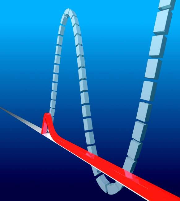
3 I S -limiter The world s fastest switching device Reduces substation cost Solves short-circuit problems in new substations and substation extensions Optimum solution for interconnection of switchboards and substations In most cases the only technical solution Tried and tested in thousands of installations Worldwide in service The peak short-circuit current will never be reached The short-circuit current is limited at the very first current rise 3
4 Short-circuit currents too high? The I S -limiter, a switching device with extremely short operating time, solves the problem. A short-circuit downstream from an outgoing feeder breaker is assumed. The oscillogram shown below indicates the course of the short-circuit currents in the first half wave. A short-circuit current of 25 ka can flow to the short-circuit point through any transformer. That is twice as much as the switchgear can withstand. The course of the current (i 2 ) which flows through the I S -limiter has been demonstrated in numerous short-circuit tests is as shown below. It can be seen that the current i 2 flowing through the I S -limiter, is limited so rapidly that it cannot contribute at all to the peak value of the short-circuit current i 1 + i 2 at the short-circuit point. The switchgear is therefore at no point subjected to any higher than the permissible current. k 25 ka k 25 ka kperm. 25 ka Single line diagram of a bus tie for a system with I" k = 25 ka and with an I S -limiter i 126 ka i = i 1 + i 2 without I S -limiter Current i = i 1 + i 2 at the short-circuit point 63 ka i 1 i = i 1 + i 2 with I S -limiter i 2 t Current i = i 1 + i 2 at the short-circuit point 4
5 Questions and answers regarding the I S -limiter 1. What is the peak short-circuit current? The peak short-circuit current i peak is the maximum instantaneous value of the current after the short-circuit occurs. Due to the peak short-circuit current the electrical system is subjected to mechanical stresses created by magnetic forces. 3. How can switchboards which are only dimensioned for 2 x I K be operated with four transformers without any risk of overload and without losses? I k I k I k I k peak By installing an I S -limiter between the busbar sections 1-2 and 3-4. (This is only one of the many possibilities for the use of an I S -limiter. See page 18 for further examples.) Due to the AC short-circuit current the system is subjected to thermal stresses from electrical heat. 2. Why does the peak short-circuit current have to be limited? x I k 2 x I k 3 x I k 4 x I k 4. How does the I S -limiter work? The I S -limiter consists of two parallel conductors. The main conductor conducts the high operating current (up to A). After tripping, the parallel fuse limits the short-circuit current during the first current rise (in less than 1 ms). I k t Transformers: Because otherwise insufficiently dimensioned switchboards, switches, current transformers, cables, etc. would be destroyed by the dynamic effects of the current. 5

6 5. How is the main conductor interrupted in less than a thousandth of a second? Mechanical stored energy systems cannot interrupt a circuit of e.g. a rated current of 2000 A in such a short time. We use a small charge. 7. Can I S -limiter inserts be refurbished after interruption of a short-circuit? Yes! They can be refurbished at the manufacturer s works. The costs are low. The opened main conductor, the parallel fuse and the charge are replaced. All other parts can be re-used Current transformer (detects the short-circuit current) 2. Measuring and tripping device (measures the current and provides the triggering energy) 3. Pulse transformer (converts the tripping pulse to busbar potential) 4. Insert holder with insert (conducts the operating current and limits the short-circuit current) 6. What overvoltages occur as a result of the sudden interruption of the current? 8. Does the I S -limiter trip on every short-circuit? No! The I S -limiter only trips when the system is at risk. Small short-circuit currents are interrupted by the circuit-breakers. Short-circuit current limited by the fuse element t The main conductor is suddenly interrupted, but not the entire current path. On separation of the main conductor, the current flows through the fuse, which interrupts the current. The overvoltage occurring on interruption by the fuse is considerably below the permissible levels set down in IEC 282-1/VDE 0670 Part 4. 6
7 9. How does the I S -limiter distinguish between minor and serious shortcircuits? The measuring and tripping device of the I S -limiter detects the instantaneous current level and the rate of current rise. The I S -limiter only trips when both set response values are reached. 11. How often does an I S -limiter trip? Experience shows that an I S -limiter trips once every four years on average, applied to 2500 I S -limiters in service. The rate of current rise ( ) dt is high with high short-circuit currents is low with low short-circuit currents di 10. What experience is available with the operation of I S -limiters? Since the invention of the I S -limiter by ABB Calor Emag in 1955, several thousand devices have been successfully used in DC, AC and particularly in three phase systems. We can look back on 45 years of good operating experience worldwide. More and more customers are selecting the I S -limiter when they need high shortcircuit currents to be safely limited and electrical systems and distribution networks to be economically built or expanded. 12. What currents can the I S -limiter interrupt? Tests at KEMA to date have demonstrated 12 kv 210 ka RMS 17.5 kv 210 ka RMS 24 kv 140 ka RMS 36/40.5 kv 140 ka RMS The function and applications of the I S -limiter are explained in the following pages with numerous examples. Discuss your short-circuit problems with us. We always find a commercially interesting and technically elegant solution with the I S -limiter. 7

8 The function of the I S -limiter The rising demand for energy world-wide requires more powerful or additional transformers and generators, and an increasing interconnection of the individual supply networks. This can lead to the permissible short-circuit currents for the equipment being exceeded and thus parts of the equipment being dynamically or thermally destroyed. The replacement of existing switchgear and cable connections by new equipment with higher short-circuit strength is often technically impossible or uneconomical for the user. The use of I S -limiters reduces the short-circuit current in new systems and expansions to existing systems, thus saving cost. Circuit-breakers cannot provide any protection against unduly high peak short-circuit currents, as they are too slow. Only the I S -limiter is capable of detecting and limiting a short-circuit current at the first rise, i.e. in less than 1 ms. The maximum instantaneous current occurring remains well below the level of the peak short-circuit current. In comparison with complex conventional solutions, the I S -limiter has both technical and economic advantages when used in transformer or generator feeders, in switchgear sectionalizing and connected in parallel with reactors. The I S -limiter is in every regard the ideal switching device to solve the short-circuit problems for switchgear in power stations, in heavy industry and at utilities. 8 I S -limiter connected in parallel with a reactor fixed mounted
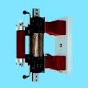
9 Design I S -limiters for three-phase systems basically consist of: three I S -limiter insert holders, three I S -limiter inserts, three tripping current transformers, a measuring and tripping device. I S -limiter insert holders The I S -limiter insert holder comprises: base plate 1, insulator 2, insulator with pulse transformer 6 and telescopic contact 5, pole heads with clamping device 3 for the reception of the I S -limiter insert. The operation of the clamping device will be done with two levers. Only for insert holder I r 2500 A and 12 kv/17.5 kv the insert are fixed with two bolts. Pulse transformer The location of the pulse transformer depends on the rated voltage: for 17.5 kv, in the lower insulator 6 only, for 24/36 kv, in the upper and lower insulators. The pulse transformer transmits the tripping pulse from the tripping device (Figure 3) to the charge 10 in the I S -limiter insert, and at the same time ensures electrical isolation of the tripping device from the charge which is at system potential. I S -limiter insert The I S -limiter insert is the switching element proper. In a sturdy insulating tube 8, the insert contains the main conductor, designed as a bursting bridge 9, which encloses a charge 10. On tripping, this charge is triggered and the main conductor opens at the rupture point Figure 1: I S -limiter insert holder with insert for 12 kv, 2000 A 1 Base plate 2 Insulator 3 Pole head with clamping device 4 Fuse 5 Telescopic contact 6 Insulator with pulse transformer Figure 2: I S -limiter insert 4 Fuse 7 Fuse indicator 8 Insulating tube 9 Bursting bridge 10 Charge 11 Main conductor indicator 12 Fuse element 9

10 The current commutates to the parallel high rupture capacity fuse 4. The fuse element 12 in the HRC fuse melts, thus limiting the further current rise. The current is interrupted at the next voltage zero passage. Tripping current transformer The tripping current transformers are used to measure the current flowing through the I S -limiter. They are located directly in series with the I S -limiter. The I S -limiter current transformer is externally identical to a conventional current transformer and is designed as a post or bushing type current transformer. It s remarkable features are: an extremely high overcurrent factor, an iron core with air gap to keep the remanent induction low a low impedance shield between the primary and secondary winding. Measuring and tripping device The measuring and tripping device is accommodated in a sheet steel control cabinet (Figure 3) or in the low voltage compartment of the I S -limiter panel. The functional groups within the control cabinet or low voltage compartment are combined such as to form replaceable units and are partly mounted on hinged frames. The measuring and tripping device includes: a power unit to provide the necessary auxiliary DC voltages, a main switch which allows the tripping system to be switched on and off at any time, and additionally a monitoring module, one tripping unit for each phase, which monitors the current flowing in the relevant phase and on tripping provides the energy for triggering of the charge in the corresponding I S -limiter insert, an indication unit with five flag indicator relays: one relay per phase for trip signalling, one relay for monitoring of readiness for operation, one relay for monitoring of the supply voltages, an anti-interference unit to protect the measuring and tripping assemblies from interference pulses from the outside, which could possibly cause malfunction. The connecting wires from the measuring and tripping device to the current transformers, to the I S -limiter insert holders and to the AC voltage supplies are routed via the anti-interference unit. W H D Width (W) : 600 mm Height (H) : 1450 mm Depth (D) : 300 mm Weight : 100 kg Figure 3: Measuring and tripping device 10
11 Function of the I S -limiter The I S -limiter consists in principle of an extremely fast switch, able to carry a high rated current but having a low switching capacity, and a high rupturing capacity fuse arranged in parallel. In order to achieve the desired short opening time, a small charge is used as the energy store for opening of the switch (main conductor). When the main conductor is opened, the current continues to flow through the parallel fuse, where it is limited within 0.5 ms and then finally interrupted at the next voltage zero passage. The current flowing through the I S -limiter is monitored by an electronic measuring and tripping device. At the very first rise of a short-circuit current, this device decides whether tripping of the I S -limiter is necessary. In order to reach this decision, the instantaneous current and rate of current rise at the I S -limiter are constantly measured and evaluated. When the setpoints are simultaneously reached or ex-ceeded, the I S -limiter trips. The three phases are operated independently of one another. The loss-free conduction of a high operating current on the one hand and the limitation of the short-circuit current at the first current rise on the other hand are made possible by distributing these two functions of the I S -limiter between two conductors. In comparison with reactors, the I S -limiter avoids voltage drops and does not contribute to the peak shortcircuit current. Power unit A DC voltage of 150 V generated in the power unit is used as the charging voltage for the tripping capacitors and at the same time as the supply voltage for the electronics. As far as necessary, the supply voltage is divided and stabilized within the individual assemblies. A watchdog module in the power unit constantly monitors the most important functions of the three tripping units V Power unit Tripping unit phase L1 Tripping unit phase L2 Tripping unit phase L3 G 1 A 2 L1 A 2 L2 A 2 L3 H 106 H 116 H 1L1 H 1L2 H 1L3 A 4 I S -limiter not ready Phase L1 tripped Phase L2 tripped Phase L3 tripped U Anti-interference unit A 3 F 116 L 1 L 2 L 3 Q 6 L 1 T1 L1 Q 6 L 2 T1 L2 Q 6 L 3 T1 L3 Figure 4: Schematic diagram of the I S -limiter equipment G1 Power unit A2 Tripping units A3 Anti-interference unit A4 Indication unit F116 Miniature circuit-breaker for supply voltage Q6 I S -limiter (insert holder and insert) T1 I S -limiter tripping transformer 11
12 Tripping unit The current supplied by the tripping transformers for the corresponding phases is monitored in the tripping units. The three tripping units work independently of each other. Both the rate of current rise and the instantaneous current value are used as criteria for tripping. Both variables are converted into proportional voltages and supplied via logical gates to an electronic measuring element. The latter provides an output signal when the rate of current rise and the instantaneous current value have both simultaneously reached the response value of the measuring element. The output signal from the measuring element then activates a thyristor, which discharges a capacitor via the pulse transformer in the I S -limiter insert holder to the charge. At the same time, this discharge excites the corresponding flag indicator relay "I S -limiter tripped" in the indication unit. Test socket connector V Measuring element 1 Trigger pulse emitter C1 T3 R Z T1 T2 L1 R5 R6 R3 R2 R1 R R S Measuring element 2 Figure 5: Schematic diagram of a measuring and tripping unit T1 I S -limiter tripping transformer T2 Intermediate transformer of the tripping unit T3 Pulse transformer L1 Measuring inductance R1.. R6 Setting resistors C1 Tripping capacitor R S Discharge resistor Charge R Z 12


13 Testing the I S -limiter As with every other protective device, I S -limiters should also be checked at regular intervals. There are special testing sets available for those tests which can be performed by the operator or by ABB Calor Emag. These test sets consist of a test equipment and a test insert or a test plug and a test insert. The test plug is used to check the voltages and the functions of the tripping system. The user friendly test equipment facilitates further tests such as determination of the response voltages of the measuring elements, and testing and setting of the modules of the measuring circuits. During testing, the I S -limiter insert is replaced by the test insert. The test insert contains a neon lamp as an indicator, which lights up when a tripping pulse is received. Figure 6: I S -limiter insert holder with test insert Figure 7: Test plug H W D Width (W) : 400 mm Height (H) : 215 mm Depth (D) : 320 mm Weight : 11 kg Figure 8: Test equipment 13
.")
14 The range A. I S -limiter as loose equipment supply In this case the insert holders, the inserts and the tripping current transformers are installed in an already existing panel. The equipment supply generally comprises: three insert holders, three inserts, three tripping current transformers, one measuring and tripping device (Figure 3). W H D Technical data Rated voltage V Rated current A 1250/2000/3000/4500/5000 1) 1250/ /3000/4000 1) Rated power-frequency withstand voltage kv Rated lightning impulse withstand voltage kv Interrupting current ka RMS up to 140 up to 210 up to 210 I S -limiter insert holder kg 23/27.5/42/78 23/ I S -limiter insert kg 10/10.5/11/14 12/ I S -limiter Width W mm 180/206/ insert holder Height H mm 637/651/754/ / with insert Depth D mm 493/500/420/ / ) With cooling fan Frequency: 50/60 Hz For higher rated currents, insert holders with inserts are connected in parallel. 14
 1250/2000/2500 1) 38 38 50 75 95 95 125 200 up to")

15 / / /3000/4000 1) 1250/1600/2000/3000 1) 1250/2000/2500 1) up to 210 up to 210 up to 140 up to / /31.5/ / /19.5/ / /754/ / /560/

16 B. Truck mounted I S -limiter in a switchgear panel The I S -limiters can also be installed in a metal-clad switchgear panel. The withdrawable truck with the three I S -limiter insert holders and inserts has the function of a disconnector. The three tripping current transformers are fixed mounted in the panel and the measuring and tripping device is mounted in the low voltage compartment. Truck mounted I S -limiter in a switchgear panel 16
17 I S -limiter panels with truck Rated Rated Rated Rated Dimensions Weight voltage current power-frequency lightning impulse including withstand voltage withstand voltage I S -limiter truck kv A kv kv Height Width Depth kg mm mm mm approx ) ) approx ) ) approx ) 1) With cooling fan. For higher currents, insert holders with inserts are connected in parallel. C.Fixed mounted I S -limiter in a switchgear panel The I S -limiters for low voltage, 12 kv, 17.5 kv and 24 kv are also available as fixed mounted equipment in a metal-clad switchgear panel. The three I S -limiter insert holders with the I S -limiter inserts and the three tripping current transformers are fixed mounted in the panel. The measuring and tripping device is mounted in the low voltage compartment. The I S -limiter (fixed mounted) for 36 kv/40.5 kv is available in a metal-enclosed switchgear panel. Same as for loose equipment supply, the measuring and tripping device is installed in a separate sheet steel cabinet (Figure 3). For all fixed mounted I S -limiters the electrical data are the same as for loose equipment supply. Dimensions and weights on request. 17
18 Applications I S -limiters in system interconnections I S -limiters are frequently used in interconnections between systems or in bus sections which would not be adequately short-circuit proof when connected by a circuit-breaker. Each partial system should have at least one incoming feeder, so that power supply to each partial system can be maintained on tripping of the I S -limiter (Figure 9). There is a large number of advantages for the operation under normal conditions of bus sections connected by I S -limiters: Reduction of the series network impedance. The voltage drops caused by load surges (e.g. of starting of motors) can be significantly reduced. Improvement of the current distribution at the feeder transformers. The load dependent losses of the feeder transformers are reduced. Increased reliability of the power supply. On failure of one feeder transformer, the load is taken over by the other feeder transformers without current interruption. The cost for an otherwise required new switchboard with higher short-circuit capacity will be saved. If a short-circuit occurs within a system or in an outgoing feeder, the I S -limiter trips at the first rise of the short-circuit current and divides the busbar system into two sections before the instantaneous current reaches an inadmissible high level. After tripping of the I S -limiter, the short-circuit is only fed by the transformer in the part of the system affected by the shortcircuit. The short-circuit current is now selectively interrupted by the circuit-breaker. A remarkable advantage of the use of an I S -limiter is that the voltage in the part of the system not affected by the short-circuit only drops for a fraction of a millisecond so that even sensitive loads (e.g. computers) remain protected from drops in the system voltage. For this reason the I S -limiter can also excellently be used as a reliable switchgear suitable between an unprotected and a protected switchboard or section of a switchboard. Figure 9: I S -limiter in a bus section 18
19 I S -limiters used as a link between public networks and consumer owned power supply systems The decentralization of power supply leads to systems with their own power generating facilities being interconnected with public supply networks. The additional short-circuit current from generators leads to the permissible short-circuit current in the utility network being exceeded. The most appropriate technical solution and mostly the only one is the installation of an I S -limiter in the interconnection with the public utility network (Figure 10). If necessary, the I S -limiter can be provided with a directional tripping criterion. This requires three additional current transformers in the neutral connections of the generators. The I S - limiter then only trips on short-circuits in the public supply network if a generator is in operation. I S -limiter in parallel with a reactor The I S -limiter can also be connected in parallel with a reactor (Figure 11). If a short-circuit occurs behind the reactor, the I S -limiter trips and the current commutates at the first current rise to the parallel reactor, which then limits the shortcircuit current to the permissible level. For normal operation, the I S - limiter bridges the reactor coil. This avoids: Current dependent copper losses and the associated operating costs of the reactor. Current dependent voltage drop at the reactor, which frequently causes major difficulties on start-up of big motors. Control problems with the generator. I" = 15 ka kt 10 kv 3 ~ 50 Hz I" = 25 ka k perm I" = 16 ka k perm I" = 3 ka kg I S ~ Figure 10: I S -limiter in connecting point with a public supply network Figure 11: I S -limiter in parallel with a reactor in a generator feeder 19
20 Use of more than one I S -limiter with selectivity In order to achieve selectivity in a switchboard or switchboards with more than one I S -limiter installed, additional tripping criteria as current summation or differences or comparison of current directions are required. If in case of two I S -limiters installed in a switchboard selective tripping is required, a measurement of the total current becomes necessary. The I S -limiter trips as follows: Short-circuit in section A: Only I S -limiter no. 1 trips. Short-circuit in section B: I S -limiter no. 1 and no. 2 trip. Short-circuit in section C: Only I S -limiter no. 2 trips. For measurement of the total current, transformer feeders must be additionally equipped with one CT set each. The total current I sum1 is equal to the current (I T1 ) of transformer T1 plus the current (I Is-1 ) flowing through the I S -limiter 1. The total current I sum2 is equal to the current of transformer T2 plus the currents flowing through I S -limiter 1 and 2. The total current I sum3 is equal to the current of transformer T3 plus the current flowing through I S -limiter 2. The tripping criteria of the I S -limiters correspond to a logic and function. The I S -limiter 1 trips in case of short-circuits in section A, if the current of I S -limiter 1 and the total current I sum1 reach or exceed their response values simulaneously. The same is applicable for section C. In case of a shortcircuit in section B I S -limiters 1 and 2 trip. The summation of the currents corresponds to the principle of the adding up of currents in a busbar protection system. The only difference is the nonrequirement of current transformers in the outgoing feeders, i.e. the requirement of material is negligable. With this principle up to 5 transformers have so far been connected in parallel, using 4 I S -limiters only. The principle ensures that always only the I S -limiter or these I S -limiters trip, which are closest to the point of short-circuit. Figure 12: Schematic diagram-i S -limiter with summation of currents 20
21 Please send by mail or fax +49/2102/ to: Sender: ABB Calor Emag Mittelspannung GmbH Postfach D Ratingen Questionnaire on the use of I S -limiters in medium and low voltage three-phase systems We require the following data for a quotation and design of an I S -limiter 1. Operating Voltage: 2. Rated Current: 3. Frequency: 4. In order to calculate the tripping and setting values we need: Single line diagram of the installation with the following data: Initial symmerical short-circuit current I K of generators, transformers, the grid, motor contribution and the permissible shortcircuit current of the switchboard. Rated power of motors over 2 MW connected to the same voltage level the I S -limiter is installed. Rated capacity of capacitor banks and the inductance in series connected to the same voltage level the I S -limiter is installed. Rated power of the biggest transformer, energised from the same voltage level where the I S -limiter is located. Single Line Diagram. 5. Which parts of the system should be protected? Please note that more than one I S -limiter can be installed in one system and we can realise selectivity between I S -limiters. 6. Requirements for the installation: It must be possible to insulate the I S -limiter to that the I S -limiter insert can be replaced after tripping. There must be a circuit breaker in series with the I S -limiter (except the I S -limiter is in parallel to a reactor). 21
22 7. We are able to deliver the I S -limiter in different designs. Which design do you need? I S -limiter as loose delivered components for installation in a cubicle of your own design I S -limiter in a cubicle type ZS1, truck mounted (up to 24 kv) I S -limiter in a cubicle type ZS1, fixed mounted (up to 24 kv) I S -limiter in a cubicle type ZE, fixed mounted (25 to 40.5 kv) 9. Remarks: 8. The I S -limiter tripping device needs three auxiliary voltage supplies: a) two independent AC supplies (50 or 60 Hz, power consumption max. 40 VA). Main supply should be taken from the system to be protected via voltage transformer. Stand-by supply e.g. from lighting grid (independent from first!). b) one supply voltage (AC or DC) for annunciation purposes (power consumption max. 20 VA). Which AC voltages are available? as main supply: V Hz as stand-by supply: V Hz Which voltage for annunciation is available? V DC; AC; 22
23 23
24 Leaflet no. DECMS E Printed in Germany ( PPI) We reserve the right to make changes in the course of technical development. ABB Calor Emag Mittelspannung GmbH Oberhausener Strasse 33 Petzower Strasse 8 D Ratingen D Glindow Phone: +49(0)21 02/ , Fax: +49(0)21 02/ calor.info@de.abb.com Internet:
ABB AG - EPDS. I S -limiter The worldʼs fastest limiting and switching device
 ABB AG - EPDS The worldʼs fastest limiting and switching device Agenda The world s fastest limiting and switching device Customers Function: Insert-holder with insert Comparison: I S -limiter Circuit-breaker
10. DISTURBANCE VOLTAGE WITHSTAND CAPABILITY
 9. INTRODUCTION Control Cabling The protection and control equipment in power plants and substations is influenced by various of environmental conditions. One of the most significant environmental factor
VI 3 - i TABLE OF CONTENTS
 VI 3 - i TABLE OF CONTENTS 3 PROJECT SPECIFIC DATA... 1 3.1 DEFINITIONS... 1 3.1.1 Design Data, High and Medium Voltage... 1 3.1.2 Design Data, Low Voltage Equipment... 2 3.1.3 Phase Relationship... 3
Numbering System for Protective Devices, Control and Indication Devices for Power Systems
 Appendix C Numbering System for Protective Devices, Control and Indication Devices for Power Systems C.1 APPLICATION OF PROTECTIVE RELAYS, CONTROL AND ALARM DEVICES FOR POWER SYSTEM CIRCUITS The requirements
Miniature circuit-breakers S 280 UC series. System pro M. Technical data
 Technical data 11 Robbie Rd. / Avon, MA 02322 T:(508)513-1000 F:(508)513-1100 70 Ernest St. / Providence, RI 02905 T:(401)781-7100 www.controllerservice.com System pro M Prior to connection of aluminum
Catalogue 1SFC en, Edition 3 November 2003 Supersedes Catalogue 1SFC en, Edition 2 November Arc Guard System TVOC
 Catalogue 1SFC 266006-en, Edition 3 November 2003 Supersedes Catalogue 1SFC 266006-en, Edition 2 November 2000 Arc Guard System TVOC System units The two units of the are used as below: Approvals 1. with
10/2 Product overview. 10/3 4AC3 0, 4AC3 1 bell transformers. 10/5 4AC AC3 6 transformers for permanent loads. 10/8 4AC2 4 power supply units
 BETA Switching Transformers, Bells and Socket Outlets /2 Product overview /3 4AC3 0, 4AC3 1 bell transformers /5 4AC3 4... 4AC3 transformers for permanent loads /8 4AC2 4 power supply units / 7LQ2 2 bells
Excitation Systems THYRIPART. Compound-Excitation System for Synchronous Generators. Power Generation
 Excitation Systems Compound-Excitation System for Synchronous Generators Power Generation Operating Characteristics Load dependent Short circuit supporting Low voltage gradient dv/dt Black start capability
Residual Current Operated Circuit-Breakers (RCCBs)
") Product Overview Residual Current Operated Circuit-Breakers (RCCBs) Residual current operated circuit-breakers Number of poles Rated current A Rated residual current ma MW Auxiliary contacts can be mounted
Product Overview Residual Current Operated Circuit-Breakers (RCCBs) Residual current operated circuit-breakers Number of poles Rated current A Rated residual current ma MW Auxiliary contacts can be mounted
Neutral Earthing. For permanent or temporary neutral earthing in HV systems
 Neutral Earthing Resistors RESISTORS For permanent or temporary neutral earthing in HV systems For continuous or temporary low-resistance neutral grounding in medium voltage systems Neutral point connection
MV ELECTRICAL TRANSMISSION DESIGN AND CONSTRUCTION STANDARD. PART 1: GENERAL 1.01 Transformer
 PART 1: GENERAL 1.01 Transformer A. This section includes liquid filled, pad mounted distribution transformers with primary voltage of 12kV or 4.16kV (The University will determine primary voltage), with
1% Switchgear and Substations
 1% Switchgear and Substations Switchgear and substations are not always matters of concern for transmitter designers, -because they are often part of the facilities of a typical installation. However,
TECHNICAL DESCRIPTION TD-77A/3 170 KV COMPACT GAS INSULATED INTEGRATED SUBSTATION MODULES
 INDEPENDENT POWER TRANSMISSION OPERATOR S.A. TNPRD/ SUBSTATION SPECIFICATION & EQUIPMENT SECTION October 2014 TECHNICAL DESCRIPTION 170 KV COMPACT GAS INSULATED INTEGRATED SUBSTATION MODULES I. SCOPE This
Protection of Electrical Networks. Christophe Prévé
 Protection of Electrical Networks Christophe Prévé This Page Intentionally Left Blank Protection of Electrical Networks This Page Intentionally Left Blank Protection of Electrical Networks Christophe Prévé
Functional Range. IWE - Earth Fault Relay. C&S Protection & Control Ltd.
 Functional Range - Earth Fault Relay C&S Protection & Control Ltd. 2 Contents Page No. 1. Application 2. Operating Principle. Current Transformer Connections 5. Connections, Contact Arrangement and Setting
Busbars and lines are important elements
 CHAPTER CHAPTER 23 Protection of Busbars and Lines 23.1 Busbar Protection 23.2 Protection of Lines 23.3 Time-Graded Overcurrent Protection 23.4 Differential Pilot-Wire Protection 23.5 Distance Protection
Electrical Description
 History of this Document Rev. no.: Date: Description of change 0 First edition 2 2003-10-08 Section 3: The rated power of the transformer can be increased by 40% if they are equipped with 6 fans for forced
ELECTRICAL POWER ENGINEERING
 Introduction This trainer has been designed to provide students with a fully comprehensive knowledge in Electrical Power Engineering systems. The trainer is composed of a set of modules for the simulation
Alternative Coupling Method for Immunity Testing of Power Grid Protection Equipment
 Alternative Coupling Method for Immunity Testing of Power Grid Protection Equipment Christian Suttner*, Stefan Tenbohlen Institute of Power Transmission and High Voltage Technology (IEH), University of
MEDIUM VOLTAGE COMPACT STARTER TYPE KAE
 MEDIUM VOLTAGE COMPACT STARTER TYPE KAE up to 5 MW up to 17,5 kv up to 400 A Mocotech presents the compact motor starter t ype KAE with integrated autotransformer, switches, control and many more advantages.
Index. Capacitor Switching - 2 Contactors. Typical Circuit Diagram 2. Auxiliary Contact Blocks 2. Contactors 3. Dimensions 3. Technical Data 4,5,6
 Index Index Page Capacitor Switching - 2 Contactors Typical Circuit Diagram 2 Auxiliary Contact Blocks 2 Contactors 3 Dimensions 3 Technical Data 4,5,6 Contactor operation 7 Function 8 Construction 9 Oscillogram
Stabilized Differential Relay SPAD 346. Product Guide
 Issued: July 1998 Status: Updated Version: D/21.03.2006 Data subject to change without notice Features Integrated three-phase differential relay, three-phase overcurrent relay and multiconfigurable earth-fault
Capacitor Switching Contactors
 Capacitor Switching D385E51 Technical catalogues and news under: www.benedict.at Motor-Starter Mini- Overload Relays Capacitor Switching Motor-Starters Modular Circuit Breakers M4-32T... up to 32A M4-32R..
Sensor Technology. Applications for medium voltage
 Sensor Technology Applications for medium voltage Contents Introduction to sensor technology... 3 Sensors versus instrument transformers... 6 Advantages for builders and users of switchgear... 7 The impact
Onsite Mobile AC High Voltage Test System
 TSGMF(T) series Onsite Mobile AC High Voltage Test System Onsite mobile AC high voltage test systems are used for withstand voltage testing, partial discharge measurement, tan delta measurement to instrument
Low voltage circuit breakers
 Comprehensive Catalogue 2006 Super Solution Low voltage circuit breakers A-4. Technical information TD & TS MCCB Index Temperature derating Power dissipation / Resistance Application Primary use of transformer
Fixed Series Compensation
 Fixed Series Compensation High-reliable turnkey services for fixed series compensation NR Electric Corporation The Fixed Series Compensation (FSC) solution is composed of NR's PCS-9570 FSC control and
SRA 2250/6 RESISTOR ARS-01 RESISTOR AUTOMATICS
 ELECTRICAL ENGINEERING DIVISION Distribution Network Department SRA 2250/6 RESISTOR ARS-01 RESISTOR AUTOMATICS ELA T150.2 en SRA 2250/6 Resistor specification The SRA 2250/6 Resistor is intended to increase
Gas-Insulated Medium-Voltage Switchgear siemens.com/8dab12
 8DB 12 blue GIS Gas-Insulated Medium-Voltage Switchgear siemens.com/8dab12 Features Gas-insulated switchgear (GIS) type 8D/B has been an integral part of the medium-voltage portfolio at Siemens for more
Residual Current Operated Circuit-Breakers (RCCBs)
") Product overview Residual Current Operated C ircuit-breakers (RCCBs) Number of poles Rated fault current I n ma Rated current I n A MW Auxiliary switches can be mounted (Type A) (Type B) 5SM1and 5SM3 RCCBs
Product overview Residual Current Operated C ircuit-breakers (RCCBs) Number of poles Rated fault current I n ma Rated current I n A MW Auxiliary switches can be mounted (Type A) (Type B) 5SM1and 5SM3 RCCBs
Single Line Diagram of Substations
 Single Line Diagram of Substations Substations Electric power is produced at the power generating stations, which are generally located far away from the load centers. High voltage transmission lines are
Utility System Lightning Protection
 Utility System Lightning Protection Many power quality problems stem from lightning. Not only can the high-voltage impulses damage load equipment, but the temporary fault that follows a lightning strike
MINISTRY OF ELECTRICITY
 MINISTRY OF ELECTRICITY IRAQ SUPERGRID PROJECTS 400/132 KV GIS SUBSTATIONS VOLUME 3 TECHNICAL SCHEDULES JANUARY 2007 LIST OF REVISIONS 1 2 3 4 5 Current Rev. Date 19.11.04 18.03.05 Aug 05 Oct 05 Jan 07
SGMF(T) series. Onsite Mobile AC High Voltage Test System. Applications:
 series. Onsite Mobile AC High Voltage Test System. Applications:") SGMF(T) series Onsite Mobile AC High Voltage Test System On-site AC high voltage test systems are used for voltage withstanding test, partial discharge measurement, tan delta measurement on those instrument
SGMF(T) series Onsite Mobile AC High Voltage Test System On-site AC high voltage test systems are used for voltage withstanding test, partial discharge measurement, tan delta measurement on those instrument
KNX Powerline PL 110. KNX Association
 KNX Powerline PL 110 Table of Contents 1 Introduction...3 2 Standardisation...3 3 Transmission Process...4 3.1 Phase Coupling...5 3.2 Telegram Transmission...6 3.2.1 Training Sequence...6 3.2.2 Preamble
NEO TELE-TRONIX PVT. LTD. 6/7 Bijoygarh, Kolkata , Tel : ; Fax :
 NEO TELE-TRONIX PVT. LTD. 6/7 Bijoygarh, Kolkata - 700 032, Tel : 033 2477 3126; Fax : 033 2477 2403 www.ntplindia.com SPECIFICATION NTPL MAKE MICRO-CONTROLLER BASED AUTOMATIC 50KV/10A AC HIGH VOLTAGE
POWER FACTOR CORRECTION. HARMONIC FILTERING. MEDIUM AND HIGH VOLTAGE SOLUTIONS.
 POWER FACTOR CORRECTION. HARMONIC FILTERING. MEDIUM AND HIGH VOLTAGE SOLUTIONS. This document may be subject to changes. Contact ARTECHE to confirm the characteristics and availability of the products
MINI-PS AC/2X15DC/1
 MII-PS-100-240AC/2X15DC/1 Power supply unit ITERFACE Data sheet 100299_en_04 1 Description PHOEIX COTACT - 2010-10-20 Features MII POWER is the extremely slim power supply unit with constructional widths
DMRC ELECTRICAL STANDARDS & DESIGN WING (DESDW)
") DELHI METRO RAIL CORPORATION LIMITED DMRC ELECTRICAL STANDARDS & DESIGN WING (DESDW) SPECIFICATION NO. DMES- 0005/ DMRC-E-TR-TRANSF-05 SPECIFICATIONS FOR THREE PHASE 33 kv/415 V AUXILIARY Issued on: Date
DELHI METRO RAIL CORPORATION LIMITED DMRC ELECTRICAL STANDARDS & DESIGN WING (DESDW) SPECIFICATION NO. DMES- 0005/ DMRC-E-TR-TRANSF-05 SPECIFICATIONS FOR THREE PHASE 33 kv/415 V AUXILIARY Issued on: Date
General Requirements. Technical Specification LVAC Systems
 Islamic Republic of Iran Vice Presidency for Strategic Planning and Supervision General Technical Specification and Execution Procedures for Transmission and Subtransmission Networks LVAC Systems NO: 423-1
DATASHEET - ETR4-70-A. Delivery program. Timing relay, 2W, 0.05s-100h, multi-function, VAC/DC, potentiometer connection
 DATASHEET - ETR4-70-A Delivery program Timing relay, 2W, 0.05s-100h, multi-function, 24-240VAC/DC, potentiometer connection Part no. ETR4-70-A Catalog No. 031888 Eaton Catalog No. XTTR6A100H70B EL-Nummer
Conventional Paper-II-2011 Part-1A
 Conventional Paper-II-2011 Part-1A 1(a) (b) (c) (d) (e) (f) (g) (h) The purpose of providing dummy coils in the armature of a DC machine is to: (A) Increase voltage induced (B) Decrease the armature resistance
DATASHEET - ETR4-51-A. Delivery program. Technical data General. Timing relay, star-delta, 50 ms, 1W, 3-60s, VAC/DC
 DATASHEET - ETR4-51-A Timing relay, star-delta, 50 ms, 1W, 3-60s, 24-240VAC/DC Part no. ETR4-51-A Catalog No. 031884 Eaton Catalog No. XTTR6A60S51B EL-Nummer 0004133308 (Norway) Delivery program Product
TABLE OF CONTENT
 Page : 1 of 34 Project Engineering Standard www.klmtechgroup.com KLM Technology #03-12 Block Aronia, Jalan Sri Perkasa 2 Taman Tampoi Utama 81200 Johor Bahru Malaysia TABLE OF CONTENT SCOPE 3 REFERENCES
Practical Experience in On-Line Partial Discharge Measurements of MV Switchgear Systems
 Practical Experience in On-Line Partial Discharge Measurements of MV Switchgear Systems Z. Berler, I. Blokhintsev, A. Golubev, G. Paoletti, V. Rashkes, A. Romashkov Cutler-Hammer Predictive Diagnostics
For non-electrical quantities
 Controlgear 3UG3 monitoring relays 3RS17 interface converters N nsb0346h nsb0348h nsb0775h For electrical quantities For non-electrical quantities 3RS17 interface converter Selection and ordering data
High voltage engineering
 High voltage engineering Overvoltages power frequency switching surges lightning surges Overvoltage protection earth wires spark gaps surge arresters Insulation coordination Overvoltages power frequency
3 - Protection components Circuit-breakers
 Contents - Protection components Circuit-breakers for the motor protection Selection guide..............................................page /2 Thermal-magnetic motor circuit-breakers Selection guide..............................................page
Type: DILM80(110V50HZ,120V60HZ) Article No.: Sales text Contactor,37kW/400V,AC operated. Ordering information
 Article No.: Sales text Contactor,37kW/400V,AC operated. Ordering information") Type: DILM80(110V50HZ,120V60HZ) Article No.: 239399 Sales text Contactor,37kW/400V,AC operated Ordering information Connection technique Description Description Rated operational current AC 3 380 V 400
Type: DILM80(110V50HZ,120V60HZ) Article No.: 239399 Sales text Contactor,37kW/400V,AC operated Ordering information Connection technique Description Description Rated operational current AC 3 380 V 400
Tab 2 Voltage Stresses Switching Transients
 Tab 2 Voltage Stresses Switching Transients Distribution System Engineering Course Unit 10 2017 Industry, Inc. All rights reserved. Transient Overvoltages Decay with time, usually within one or two cycles
Type: DILM95(230V50HZ,240V60HZ) Article No.: Sales text Contactor,45kW/400V,AC operated. Ordering information
 Article No.: Sales text Contactor,45kW/400V,AC operated. Ordering information") Type: DILM95(230V50HZ,240V60HZ) Article No.: 239480 Sales text Contactor,45kW/400V,AC operated Ordering information Connection technique Description Description Rated operational current AC 3 380 V 400
Type: DILM95(230V50HZ,240V60HZ) Article No.: 239480 Sales text Contactor,45kW/400V,AC operated Ordering information Connection technique Description Description Rated operational current AC 3 380 V 400
Our Brands. Where we are?
 CATALOG 2019 Our Brands Aktif trade mark for Measuring, Protection, Automatic Meter Reading, Billing and Energy Management Software. by Aktif Aktif trade mark for Measuring, Protection, Control and Power
P. O. BOX 269 HIGHLAND, ILLINOIS, U.S.A PHONE FAX
 SSE-N NEGATIVE FIELD FORCING SHUNT STATIC EXCITER/REGULATOR SYSTEM Control Chassis 6 SCR Power Chassis APPLICATION The SSE-N Negative Field Forcing Exciter/Regulator is used for both new and old installations
Unit 2. Single Line Diagram of Substations
 Unit 2 Single Line Diagram of Substations Substations Electric power is produced at the power generating stations, which are generally located far away from the load centers. High voltage transmission
Capacitive voltage transformers
 Capacitive voltage transformers Outdoor operation Oil-paper insulated ECF (72 550) kv General description Capacitive voltage transformers of type ECF are used in high-voltage switchgears from 72 to 550
1. All electrical switches and outlets used shall be equal to Hubbell heavy duty, specification grade or equivalent quality.
 PART 1: GENERAL 1.01 Wiring Devices A. This section of the standard includes design requirements for wiring connections, including receptacles and switches to equipment specified in other sections. 1.02
ARC FLASH PPE GUIDELINES FOR INDUSTRIAL POWER SYSTEMS
 The Electrical Power Engineers Qual-Tech Engineers, Inc. 201 Johnson Road Building #1 Suite 203 Houston, PA 15342-1300 Phone 724-873-9275 Fax 724-873-8910 www.qualtecheng.com ARC FLASH PPE GUIDELINES FOR
EH2741 Communication and Control in Electric Power Systems Lecture 2
 KTH ROYAL INSTITUTE OF TECHNOLOGY EH2741 Communication and Control in Electric Power Systems Lecture 2 Lars Nordström larsno@kth.se Course map Outline Transmission Grids vs Distribution grids Primary Equipment
QUINT-PS-24DC/24DC/10
 QUINT-PS-24/24/10 QUINT - converter, primary switched mode, input: 24 V, output: 24 V /10 A INTERFACE Data Sheet PHOENIX CONTACT - 02/2006 Description The QUINT - converter 24 V/10 A converts the voltage
This data sheet is only valid in association with the IL SYS INST UM E user manual.
 Inline counter terminal, version for extreme conditions, 1 counter input, 1 control input, 1 output, 24 V DC, 500 ma Data sheet 106148_en_03 PHOENIX CONTACT 2015-11-04 1 Description The terminal is designed
DC VACUUM CIRCUIT BREAKER
 DC VACUUM CIRCUIT BREAKER Lars LILJESTRAND Magnus BACKMAN Lars JONSSON ABB Sweden ABB Sweden ABB Sweden lars.liljestrand@se.abb.com magnus.backman@se.abb.com lars.e.jonsson@se.abb.com Marco RIVA ABB Italy
GIS Instrument Transformers: EMC Conformity Tests for a Reliable Operation in an Upgraded Substation
 GIS Instrument Transformers: EMC Conformity Tests for a Reliable Operation in an Upgraded Substation W. Buesch 1) G. Palmieri M.Miesch J. Marmonier O. Chuniaud ALSTOM LTD 1) ALSTOM LTD High Voltage Equipment
ZS8.4 Air-insulated medium voltage switchgear
 ZS8.4 Air-insulated medium voltage switchgear Power products from ABB Future-proof solutions ABB provides utility, industrial and commercial customers with safe, reliable and smart technologies for the
Residual current circuit breakers (RCCBs)
") Residual current circuit breakers (RCCBs) Description Automatically trips in event of earth leakage fault Provides protection against direct & indirect contact with live parts Technical data IS 12640-1,
Residual current circuit breakers (RCCBs) Description Automatically trips in event of earth leakage fault Provides protection against direct & indirect contact with live parts Technical data IS 12640-1,
Excitation Systems RG3 - T4. Transistorized Excitation Systems for Synchronous Generators. Power Generation
 Excitation Systems RG3 - T4 Transistorized Excitation Systems for Synchronous Generators Power Generation Operating Characteristics Reliability High availability Digital control facilities Very good control
TeSys contactors. TeSys D contactors. IEC/EN , IEC/EN , UL 508, CSA C22.2 n 14. Protection against direct fi nger contact IP 2X
 Characteristics Contactor type LC1 D09 D18 DT20 and DT25 Environment Rated insulation voltage (Ui) Conforming to IEC 097--1, overvoltage category III, degree of pollution: 3 Conforming to UL, CSA V 00
Characteristics 5 TeSys k contactors and reversing contactors
 90 Characteristics contactors k contactors and reversing contactors Environment characteristics Conforming to standards IEC 60947, NF C 63-110, VDE 0660, BS 424 Product certifications LCp and LPp K06 to
Capacitive voltage transformers
 Capacitive voltage transformers Outdoor operation Oil-paper insulated ECF (72 550) kv General description Capacitive voltage transformers of type ECF are used in high-voltage switchgears from 72 to 550
Secondary Arresters. Figure 1. Type L secondary surge arrester rated 175 Vac, 125 Vdc.
 Surge Arresters Secondary Arresters and Protective Gaps Electrical Apparatus 235-10 GENERAL INFORMATION The necessity of providing surge arrester protection on low-voltage circuits is fundamentally the
ET 40 - Electrician Theory Examination Marking Schedule
 ET 40 - Electrician Theory Examination Marking Schedule Notes:1. means that the preceding statement/answer earns 1 mark. 2. This schedule sets out the accepted answers to the examination questions. A marker
A Review Comprehension: Guideline for Testing of HV, EHV and UHV Substation Equipment
 International Research Journal of Engineering and Technology (IRJET) eissn: 23 0056 Volume: 04 Issue: 02 Feb 2017 www.irjet.net pissn: 072 A Review Comprehension: Guideline for Testing of HV, EHV and UHV
CONTENTS. 1. Introduction Generating Stations 9 40
 CONTENTS 1. Introduction 1 8 Importance of Electrical Energy Generation of Electrical Energy Sources of Energy Comparison of Energy Sources Units of Energy Relationship among Energy Units Efficiency Calorific
UBC Technical Guidelines Section Edition Medium-Voltage Transformers Page 1 of 5
 Page 1 of 5 1.0 GENERAL 1.1 Coordination Requirements.1 UBC Energy & Water Services.2 UBC Building Operations 1.2 Description.1 UBC requirements for Substation Transformers. 2.0 MATERIAL AND DESIGN REQUIREMENTS
High-set undervoltage stage with definitetime. or inverse definite minimum time (IDMT) characteristic. Low-set undervoltage stage with definitetime
 characteristic. Low-set undervoltage stage with definitetime") Issued: 5.06.999 Status: 5.06.999 Version: B/09..00 Data subject to change without notice Features Overvoltage and undervoltage protection Single- or three-phase operation High-set overvoltage stage with
Issued: 5.06.999 Status: 5.06.999 Version: B/09..00 Data subject to change without notice Features Overvoltage and undervoltage protection Single- or three-phase operation High-set overvoltage stage with
VOLTAGE OPTIMIZATION FOR INDUSTRY, TRADE, BUSINESS AND LOCAL NETWORKS
 VOLTAGE OPTIMIZATION FOR INDUSTRY, TRADE, BUSINESS AND LOCAL NETWORKS Employing a voltage control system in a low-tension network provides independence from network fluctuations. In addition, energy-using
MEDIUM & HIGH VOLTAGE
 MEDIUM & HIGH VOLTAGE TESTING EQUIPMENT VOLTAGE WITHSTAND SGM Series Resonant Systems The SGM series are used for generating high AC voltages at a fixed frequency (mainly 50 or 60 Hz) by means of an excited
HV AC TESTING OF SUPER-LONG CABLES
 HV AC TESTING OF SUPER-LONG CABLES Stefan SCHIERIG, (Germany), schierig@highvolt.de Peter COORS, (Germany), coors@highvolt.de Wolfgang HAUSCHILD, IEC, CIGRE, (Germany), hauschild@highvolt.de ABSTRACT The
INVESTIGATION OF ENERGY LOSS IN A TRANSMISSION SUBSTATION USING ONITSHA 330/132KV AS A CASE STUDY F.O. Enemuoh, T.L. Alumona and C.H.
 INVESTIGATION OF ENERGY LOSS IN A TRANSMISSION SUBSTATION USING ONITSHA 330/132KV AS A CASE STUDY F.O. Enemuoh, T.L. Alumona and C.H. Aliche 1,2 nnamdi azikiwe university, awka, anambra state, nigeria.
XR1 Rotor Earth Fault Relay. (May 2007) Manual XR1 (Revision New)
 Manual XR1 (Revision New)") XR1 Rotor Earth Fault Relay (May 2007) Manual XR1 (Revision New) Woodward Manual XR1 GB Woodward Governor Company reserves the right to update any portion of this publication at any time. Information provided
XR1 Rotor Earth Fault Relay (May 2007) Manual XR1 (Revision New) Woodward Manual XR1 GB Woodward Governor Company reserves the right to update any portion of this publication at any time. Information provided
Pomona, CA May 24 & 25, LTC Applications - Location, Series & Preventative Auto Transformers
 Pomona, CA May 24 & 25, 2016 LTC Applications - Location, Series & Preventative Auto s siemens.com/answers Introduction Tap changer at active part Example of 3-phase tapchanger Page 2 Winding Configurations
Modeion OTHER ACCESSORIES OF MOULDED CASE CIRCUIT BREAKERS
 OTHER ACCESSORIES OF MOULDED CASE CIRCUIT BREAKERS P Other accessories DELAY UNIT Type Product code Description Weight [kg] Package [pc] BZ-BX-X230-A 36696 enables to delay the undervoltage release tripping
RAIDK, RAIDG, RAPDK and RACIK Phase overcurrent and earth-fault protection assemblies based on single phase measuring elements
 RAIDK, RAIDG, RAPDK and RACIK Phase overcurrent and earth-fault protection assemblies based on single phase measuring elements User s Guide General Most faults in power systems can be detected by applying
Overcurrent Protection / 7SJ45
 Overcurrent Protection / SJ SIPROTEC easy SJ numerical overcurrent protection relay powered by CTs Fig. / Description SIPROTEC easy SJ numerical overcurrent protection relay powered by current transformers
Shunt Reactors. Global Top Energy, Machinery & Plant Solution Provider
 Shunt Reactors Global Top Energy, Machinery & Plant Solution Provider Our Business Brief introduction of Hyosung Power & Industrial Systems PG While Hyosung is an established name for world-class electrical
XR1 Rotor Earth Fault Relay. Manual XR1 (Revision C)
") XR1 Rotor Earth Fault Relay Manual XR1 (Revision C) Woodward Manual XR1 (EN) Woodward Governor Company reserves the right to update any portion of this publication at any time. Information provided by
XR1 Rotor Earth Fault Relay Manual XR1 (Revision C) Woodward Manual XR1 (EN) Woodward Governor Company reserves the right to update any portion of this publication at any time. Information provided by
MINI-PS AC/24DC/1.3
 Power supply unit INTERFACE Data sheet 102894_en_03 1 Description PHOENIX CONTACT 2015-11-17 Features MINI POWER power supplies for MCR technology In measurement and control technology (MCR), modular electronics
Medium Voltage Products. KECA 80 C85 Indoor current sensor
 Medium Voltage Products KECA 80 C85 Indoor current sensor Parameters for Application Value Rated primary current of application up to 2 500 A Sensor Parameters Value Highest voltage for equipment, U m
Webinar: An Effective Arc Flash Safety Program
 Webinar: An Effective Arc Flash Safety Program Daleep Mohla September 10 th, 2015: 2pm ET Agenda Arc Flash Defined and Quantified NFPA 70E / CSA Z 462 - Recent Updates What is the ANSI Z10 Hierarchy of
Power Quality. Case Study. Conrad Bottu Laborelec January 2008
 Case Study Electromagnetic compatibility (EMC) study Breakdown of low voltage electronic equipment in a 25 kv substation Conrad Bottu Laborelec January 2008 Power Quality Power Quality 1 Introduction Description
Understanding Harmonics
 Understanding Harmonics Terry Gaiser Sensus What Are Harmonics? 1 » What is Power Quality?» Power quality is the degree to which both the utilization and delivery of electric power affects the performance
CDV 22, 62. Voltage Controlled Overcurrent Relay GRID PROTECTION
 PROTECTION CDV 22, 62 Voltage Controlled Overcurrent Relay CDV22 relay is used for overload and fault protection for ac generators when the sustained short circuit current is less than the full load current.
Company main topic [ Product ] TracFeed GR. English. Diode Rectifiers. Made in Germany
![Company main topic [ Product ] TracFeed GR. English. Diode Rectifiers. Made in Germany](/thumbs/86/94321877.jpg "Company main topic [ Product ] TracFeed GR. English. Diode Rectifiers. Made in Germany") Company main topic [ Product ] TracFeed GR English Diode Rectifiers Made in Germany 2 Reliable traction power supply with rectifiers from Rail power Systems Application Rectifiers with natural air cooling
Company main topic [ Product ] TracFeed GR English Diode Rectifiers Made in Germany 2 Reliable traction power supply with rectifiers from Rail power Systems Application Rectifiers with natural air cooling
PHOENIX CONTACT
 Electronic circuit breaker CLIPLINE Data sheet 102898_en_03 PHOENIX CONTACT 2010-12-17 1 Description The electronic circuit breaker can be used in applications that cover all aspects of the switched-mode
presentation contents application advantages
 presentation contents page presentation protection functional and connection schemes other connection schemes connection characteristics 9 installation 0 commissioning ordering information Sepam 00 is
* Short-circuit detection at On pushbutton. Applications. Indication. S M6801_a S11 A3 S12 S21 S23 S22 S (+)
") Safety technique Emergency stop module BO 5988 safemaster 0221562 Function diagram Pushbutton on Mains or emergencystop () K1 According to EC Directive for machines 98/37/EG According to IEC/E 60204-1
Safety technique Emergency stop module BO 5988 safemaster 0221562 Function diagram Pushbutton on Mains or emergencystop () K1 According to EC Directive for machines 98/37/EG According to IEC/E 60204-1
Design, Control and Application of Modular Multilevel Converters for HVDC Transmission Systems by Kamran Sharifabadi, Lennart Harnefors, Hans-Peter
 1 Design, Control and Application of Modular Multilevel Converters for HVDC Transmission Systems by Kamran Sharifabadi, Lennart Harnefors, Hans-Peter Nee, Staffan Norrga, Remus Teodorescu ISBN-10: 1118851560
SECTION LOW-VOLTAGE ELECT. DIST. DESIGN AND CONSTRUCTION STANDARDS _ February 2015 PART I: GENERAL
 PART I: GENERAL 1.01 Wiring Devices A. This section of the standard includes design requirements for wiring connections, including receptacles and switches to equipment specified in other sections. a.
NATIONAL CERTIFICATE (VOCATIONAL) ELECTRICAL PRINCIPLES AND PRACTICE NQF LEVEL 4 NOVEMBER 2009
 ELECTRICAL PRINCIPLES AND PRACTICE NQF LEVEL 4 NOVEMBER 2009") NATIONAL CERTIFICATE (VOCATIONAL) ELECTRICAL PRINCIPLES AND PRACTICE NQF LEVEL 4 NOVEMBER 2009 (12041004) 23 November (X-Paper) 09:00 12:00 Calculators may be used. This question paper consists of 7 pages.
NATIONAL CERTIFICATE (VOCATIONAL) ELECTRICAL PRINCIPLES AND PRACTICE NQF LEVEL 4 NOVEMBER 2009 (12041004) 23 November (X-Paper) 09:00 12:00 Calculators may be used. This question paper consists of 7 pages.
BGE STRATEGIC CUSTOMER ENGINEERING
 TABLE OF CONTENTS 1. GENERAL. 2 2. BGE SUPPLY FEEDER. 4 3. SWITCHGEAR ENCLOSURE AND ASSEMBLY. 5 4. CIRCUIT BREAKER. 9 5. SWITCHGEAR EQUIPMENT... 10 6. MAIN AND GROUND BUS.... 15 7. GROUND AND TEST DEVICE.
Application of Low-Impedance 7SS601 Busbar Differential Protection
 Application of Low-Impedance 7SS601 Busbar Differential Protection 1. Introduction Utilities have to supply power to their customers with highest reliability and minimum down time. System disturbances,