Technical catalogue. Emax. Low voltage air circuit-breakers 1SDC200006D0204
|
|
|
- Shannon Melton
- 5 years ago
- Views:
Transcription

1 Technical catalogue Emax Low voltage air circuit-breakers 1SDC200006D0204
2
3

4

5 The new Emax air circuit-breakers are the result of ABB SACE s constant commitment to look for new solutions, and of the know-how it has developed over the years. This is an incredibly innovative high quality circuit-breakers range, designed to satisfy all application requirements. The innovation of the new Emax is really outstanding from all points of view: completely re-engineered releases fitted with latest generation electronics, improved performances with the same dimensions and new applications to fulfil the latest market needs. The new electronics open a window on a world of extraordinary solutions, with connectivity options never before seen in the market. Discover the great advantages of ABB SACE s new Emax. The evolution has been going on since 1955.

6

7 Continuing the tradition of ABB SACE, the new Emax range offers performances at the top of its category. The Emax range offers you a great advantage: with the increased performances, you can use the smaller circuit-breaker frames, obtaining considerable savings both in economic terms and in physical space within the switchgear. Emax E1 now offers current ratings up to 1600A, whilst Emax E3 is enhanced by version V with top of the range performances. Always aware of the rapid changes in the market, ABB SACE has made some specific versions to cover new applications and simplify retrofitting operations.

8

9 The new Emax range shines like a light from within: the new generation of protection releases is fitted with the latest advances in electronics, offering individual bespoke solutions for control and protection. The new releases, which are amazingly versatile and simple to use, offer important innovations, such as the brand-new intuitive operator interface allowing complete control of the system with just a few simple keystrokes. Furthermore, there are new protections, new alarms and connection to handheld and laptop PCs using Bluetooth technology. The reengineered hardware architecture allows flexible and precise configuration. With the new Emax it is no longer necessary to completely replace the release - simply add the module which satisfies your requirements: a great advantage, both in terms of flexibility and customisation.

10 The new Emax have received innumerable international certifications and approval by the major shipping registers.

11 Careful selection of materials, meticulous assembly and a rigorous testing stage make the new Emax an extremely reliable and sturdy product, able to withstand high dynamic and thermal stresses for longer than any other circuit-breaker in its category. With the new standardised system of accessories studied and made for the new Emax, work becomes easier, convenient, safe and rapid. Furthermore, ABB SACE puts a highly specialised and rapid customer assistance service at your disposal. The new Emax give you that pleasant feeling of security which only such a reliable product is able to do.
12

13 Main characteristics 1 Contents Overview of the SACE Emax family Fields of application... 1/2 Construction characteristics Structure of the circuit-breakers... 1/4 Operating mechanism... 1/5 Operating and signalling parts... 1/6 Fixed parts of withdrawable circuit-breakers... 1/7 Utilization category... 1/8 Versions and connections... 1/9 Electronic releases General characteristics... 1/10 Versions available... 1/12 Rating plugs... 1/13 Compliance with Standards Standards, approvals and certifications... 1/14 A design dedicated to Quality and respect for the environment... 1/15 ABB SACE 1/1
14 Overview of the SACE Emax family Fields of application E1 E2 1 Automatic circuit-breakers E1B E1N E2B E2N E2S E2L Poles [No.] p c.-b neutral current-carrying capacity [% Iu] Iu (40 C) [A] Ue [V~] Icu ( V) [ka] Ics ( V) [ka] Icw (1s) [ka] (3s) [ka] Automatic circuit-breakers with full-size neutral conductor Poles [No.] Standard version Standard version 4p c.-b neutral current-carrying capacity [% Iu] Iu (40 C) [A] Ue [V~] Icu ( V) [ka] Ics ( V) [ka] Icw (1s) [ka] (3s) [ka] Switch-disconnectors E1B/MS E1N/MS E2B/MS E2N/MS E2S/MS Poles [No.] Iu (40 C) [A] Ue [V~] Icw (1s) [ka] (3s) [ka] Icm ( V) [ka] Automatic circuit-breakers for applications up to 1150 V AC E2B/E E2N/E Poles [No.] Iu (40 C) [A] Ue [V~] Icu (1150V) [ka] Ics (1150V) [ka] Icw (1s) [ka] Switch-disconnectors for applications up to 1150 V AC E2B/E MS E2N/E MS Poles [No.] Iu (40 C) [A] Ue [V~] Icw (1s) [ka] Icm (1000V) [ka] Switch-disconnectors for applications up to 1000 V DC E1B/E MS E2N/E MS Poles [No.] Iu (40 C) [A] Ue [V-] 750 (3p)-1000(4p) 750 (3p)-1000(4p) Icw (1s) [ka] Icm (750V) [ka] (1000V) [ka] Sectionalizing truck E1 CS E2 CS Iu (40 C) [A] Earthing switch with making capacity E1 MTP E2 MTP Iu (40 C) [A] Earthing truck E1 MT E2 MT Iu (40 C) [A] (*) The performance at 1000V is 50kA. 1/2 ABB SACE
15 E3 E4 E6 E3N E3S E3H E3V E3L E4S E4H E4V E6H E6V E4S/f E4H/f E6H/f Standard version E3N/MS E3S/MS E3V/MS E4S/MS E4S/f MS E4H/MS E4H/f MS E6H/MS E6H/f MS E3H/E E4H/E E6H/E (*) (*) (*) E3H/E MS E4H/E MS E6H/E MS E3H/E MS E4H/E MS E6H/E MS (3p)-1000(4p) 750 (3p) (4p) 750 (3p) (4p) E3 CS E4 CS E6 CS E3 MTP E4 MTP E6 MTP E3 MT E4 MT E6 MT ABB SACE 1/3

 in the withdrawable version allows the apparatus to be used in switchgear compartments 400 mm wide.")
16 Construction characteristics Structure of the circuit-breakers 1 The sheet steel structure of the Emax air circuit-breaker is extremely compact, considerably reducing overall dimensions. Safety is improved by using double insulation of the live parts and total segregation between phases. The sizes have the same height and depth for all the circuitbreakers in each version. The depth of the withdrawable version is suitable for installation in switchgear 500 mm deep. The width of 324 mm (up to 2000 A) in the withdrawable version allows the apparatus to be used in switchgear compartments 400 mm wide. Their compact dimensions also mean they can replace air circuit-breakers of any size from earlier series. 1SDC200018F0001 1SDC200019F0001 1/4 ABB SACE

17 Construction characteristics Operating mechanism The operating mechanism is of the stored energy type, operated using pre-charged springs. The springs are charged manually by operating the front lever or using a geared motor, supplied on request. The opening springs are charged automatically during the closing operation. With the operating mechanism fitted with shunt closing and opening releases and the geared motor for charging the springs, the circuit-breaker can be operated by remote control and, if required, co-ordinated by a supervision and control system. 1 ➁ OPENING ➀ CLOSING ➀ OPENING ➂ OPENING ➁ CLOSING 1SDC200020F0001 1SDC200021F0001 The following operating cycles are possible without recharging the springs: starting with the circuit-breaker open (0) and the springs charged: closing-opening starting with the circuit-breaker closed (I) and the springs charged: opening-closing-opening. The same operating mechanism is used for the entire series and is fitted with a mechanical and electrical anti-pumping device. ABB SACE 1/5

 12 Racking-in/out device (for withdrawable version only) 13 Terminal box (for fixed version only) 14 Sliding contacts (for withdrawable version only) 15 Circuit-breaker position")
18 Construction characteristics Operating and signalling parts Fixed version 1SDC200032F Caption 1 Trademark and size of circuitbreaker 2 SACE PR121, PR122 or PR123 release 3 Pushbutton for manual opening 4 Pushbutton for manual closing 5 Lever to manually charge closing springs 6 Electrical rating plate 7 Mechanical device to signal circuit-breaker open O and closed I 8 Signal for springs charged or discharged 9 Mechanical signalling of overcurrent releases tripped 10 Key lock in open position 11 Key lock and padlock in rackedin/racked-out position (for withdrawable version only) 12 Racking-in/out device (for withdrawable version only) 13 Terminal box (for fixed version only) 14 Sliding contacts (for withdrawable version only) 15 Circuit-breaker position indicator: racked-in/ test isolated /racked-out / connected/test isolated/disconnected (for withdrawable version only) Withdrawable version Note: Racked-in refers to the position in which both the power contacts and auxiliary contacts are connected; racked-out is the position in which both the power contacts and auxiliary contacts are disconnected; test isolated is the position in which the power contacts are disconnected, whereas the auxiliary contacts are connected. 14 1SDC200033F /6 ABB SACE

19 Construction characteristics Fixed parts of withdrawable circuit-breakers The fixed parts of withdrawable circuit-breakers have shutters for segregating the fixed contacts when the circuit-breaker is withdrawn from the compartment. These can be locked in their closed position using padlock devices. Caption 1 Sheet steel supporting structure 2 Single earthing clamp mounted on the left for E1, E2 and E3, double earthing clamps for E4 and E6 3 Safety shutters (protection rating IP20) 4 Terminal support base 5 Terminals (rear, front or flat) 6 Contacts signalling that the circuit-breaker is racked-in, test isolated, racked-out 7 Sliding contacts 8 Padlock device for safety shutters (on request) 9 Fastening points (4 for E1, E2, E3 and 6 for E4, E6) SDC200022F ABB SACE 1/7
20 Construction characteristics Utilization category 1 Selective and current-limiting circuit-breakers Selective (non current-limiting) circuit-breakers are classified in class B (according to the IEC Standard). It is important to know their Icw values in relation to any possible delayed trips in the event of short-circuits. The current-limiting circuit-breakers E2L and E3L belong to class A. The short-time withstand current Icw is not very important for these circuit-breakers, and is necessarily low due to the operating principle on which they are based. The fact that they belong to class A does not preclude the possibility of obtaining the necessary selectivity (e.g. current-type or time-type selectivity). The special advantages of current-limiting circuit-breakers should also be underlined. In fact, they make it possible to: significantly reduce the peak current in relation to the prospective value; drastically limit specific let-through energy. The resulting benefits include: reduced electrodynamic stresses; reduced thermal stresses; savings on the sizing of cables and busbars; the possibility of coordinating with other circuit-breakers in the series for back-up or discrimination b 6a Caption SDC200023F0001 Selective circuit-breaker E1 B-N, E2 B-N-S, E3 N-S-H-V, E4 S-H-V, E6 H-V 5b 5a SDC200024F0001 Current-limiting circuit-breaker E2 L, E3 L Sheet steel supporting structure 2 Current transformer for protection release 3 Pole group insulating box 4 Horizontal rear terminals 5-5a Plates for fixed main contacts 5b Plates for fixed arcing contacts 6-6a Plates for main moving contacts 6b Plates for moving arcing contacts 7 Arcing chamber 8 Terminal box for fixed version - Sliding contacts for withdrawable version 9 Protection release 10 Circuit-breaker closing and opening control 11 Closing springs 1/8 ABB SACE
21 Versions and connections All the circuit-breakers are available in fixed and withdrawable, three-pole or four-pole versions. Each series of circuit-breakers offers terminals made of silverplated copper bars, with the same dimensions, regardless of the rated currents of the circuit-breakers. The fixed parts for withdrawable circuit-breakers are common to each model, regardless of the rated current and breaking capacity of the relative moving parts, except for the E2S circuitbreaker which requires a specific fixed part. A version with gold-plated terminals is available for special requirements, linked to use of the circuit-breakers in corrosive environments. The availability of various types of terminals makes it possible to build wall-mounted switchgear, or switchgear to be accessed from behind with rear connections. For special installation needs, the circuit-breakers can be fitted with various combinations of top and bottom terminals. Furthermore new dedicated terminal conversion kits give Emax maximum flexibility, allowing horizontal terminals to be changed to vertical or front ones and vice versa. 1 Fixed circuit-breaker 1SDC200028F0001 1SDC200029F0001 1SDC200030F0001 1SDC200031F0001 1SDC200025F0001 1SDC200026F0001 1SDC200027F0001 Horizontal rear terminals Vertical rear terminals Front terminals Withdrawable circuit-breaker Horizontal rear terminals Vertical rear terminals Front terminals Flat terminals ABB SACE 1/9

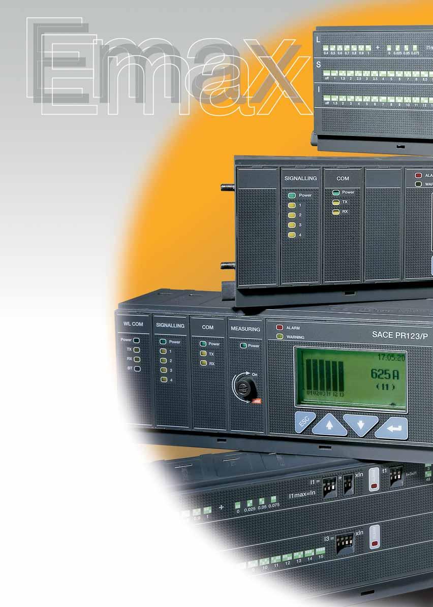
22 Electronic releases General characteristics 1 The overcurrent protection for AC installations uses three types of electronic release series: PR121, PR122 and PR123. The basic series, PR121, offers the whole set of standard protection functions, complete with a user-friendly interface. It allows discrimination of which fault caused the trip by means of the new led indications. PR122 and PR123 releases are of new concept modular architecture. It is now possible to have a complete series of protections, accurate measurements, signalling or dialogue functions, designed and customisable for all application requirements. The protection system is made up of: 3 or 4 new generation current sensors (Rogowsky coil); external current sensors (i.e. for external neutral, residual current or source ground return protection); a protection unit selected among PR121/P, PR122/P or PR123/P with optional communication module via Modbus or Fieldbus plug network (PR122/P and PR123/P only), as well as via a wireless connection; an opening solenoid, which acts directly on the circuit-breaker operating mechanism (supplied with the protection unit). 1SDC200034F0001 1/10 ABB SACE
23 General specifications of the electronic releases include: operation without the need for an external power supply microprocessor technology high precision sensitivity to the true R.M.S. value of the current trip cause indication and trip data recording interchangeability among all types of releases setting for neutral configurable: OFF-50%-100%-200% of phase setting for circuit-breakers E1, E2, E3 and E4/f, E6/f full-size versions, and E4-E6 with external neutral protection; OFF-50% for standard E4 and E6. 1 The main performance features of the releases are listed below. PR121 Protection PR121/P PR121/P PR121/P PR122 PR122/P PR122/P PR122/P PR122/P Protection Rc For all versions U OT M New modules available: Measuring opt. UV OV RV RP UF OF Communication Signalling Bluetooth (wireless link) opt. opt. opt. PR123 Protection PR123/P PR123/P For all versions OT D U UV OV RV RP M UF OF New modules available: Communication opt. Signalling Bluetooth (wireless link) opt. opt. ABB SACE 1/11
24 Electronic releases Versions available Features 1 Protection functions Rc PR121 PR122 PR123 Protection against overload with inverse long time-delay trip Selective protection against short-circuit inverse or definite short time-delay trip Second selective protection against short-circuit inverse or definite short time-delay trip Protection against instantaneous short-circuit with adjustable trip current threshold Protection against earth fault residual source ground return Residual current (1) opt. (2) D Protection against directional short-circuit with adjustable time-delay U OT UV OV RV RP M UF OF Protection against phase unbalance Protection against overtemperature (check) Protection against undervoltage opt. (3) Protection against overvoltage opt. (3) Protection against residual voltage opt. (3) Protection against reverse active power opt. (3) Thermal memory for functions L and S Underfrequency opt. (3) Overfrequency opt. (3) Measurements Currents (phases, neutral, earth fault) Voltage (phase-phase, phase-neutral, residual) opt. (3) Power (active, reactive, apparent) opt. (3) Power factor opt. (3) Frequency and peak factor opt. (3) Energy (active, reactive, apparent, meter) opt. (3) Harmonics calculation (display of wave forms and harmonics module) Event marking and maintenance data Event marking with the instant it occurred opt. (4) Chronological event storage opt. (4) Counting the number of operations and contact wear Communication with supervision system and centralised control Remote parameter setting of the protection functions, unit configuration, communication opt. (5) opt. (5) Transmission of measurements, states and alarms from circuit-breaker to system opt. (5) opt. (5) Transmission of the events and maintenance data from circuit-breaker to system opt. (5) opt. (5) Watchdog Alarm and trip for release overtemperature Check of release status Interface with the user Presetting parameters by means of dip switches Presetting parameters by means of keys and LCD viewer Alarm signals for functions L, S, I and G Alarm signal of one of the following protections: undervoltage, overvoltage, residual voltage, active reverse of power, phase unbalance, overtemperature opt. (3) Complete management of pre-alarms and alarms for all the self-control protection functions Enabling password for use with consultation in READ mode or consultation and setting in EDIT mode Load control Load connection and disconnection according to the current passing through the circuit-breaker Zone selectivity Can be activated for protection functions S, G and (PR123 only) D (1) requires a homopolar toroid for residual current protection; (2) the RC function is available with PR122LSIRc or with PR122LSIG and module PR120/V; (3) with PR120/V; (4) with BT030 communication unit; (5) with PR120/D-M 1/12 ABB SACE
25 Electronic releases Rating plugs A new concept for setting the current ratings Rating plugs Type of Rated circuit-breaker current Iu 800 E1B E1N E2B E2N E2S E2L E3N E3S E3H E3V E3L 2500 E4S, E4S/f E4H, E4H/f E4V E6H, E6H/f E6V In [A] ABB SACE 1/13

, CEI EN 60947")
 n o 73/23 EEC")


 NK (Nippon Kaiji Kyokai) The Emax")

 certification")
 Note: Contact ABB SACE for a")


26 Compliance with Standards Standards, approvals and certifications 1 SACE Emax circuit-breakers and their accessories conform to the international IEC 60947, EN (harmonized in 28 CENELEC countries), CEI EN and IEC Standards, and comply with following EC directives: Low Voltage Directive (LVD) n o 73/23 EEC Electromagnetic Compatibility Directive (EMC) nr. 89/336 EEC. The main versions of the apparatus are approved by the following Shipping Registers: RINA (Italian Naval Register) Det Norske Veritas Bureau Veritas Germanischer Lloyd Loyd s Register of Shipping Polskj Rejestr Statkow ABS (American Bureau of Shipping) RMRS (Russian Maritime Register of Shipping) NK (Nippon Kaiji Kyokai) The Emax series also has a range which has undergone certification according to the severe American UL 1066 Standards. Furthermore, the Emax series is certified by the Russian GOST (Russia Certificate of Conformity) certification organization, and is certified by China CCC (China Compulsory Certification) Note: Contact ABB SACE for a list of approved types of circuit-breakers, approved performance data and the corresponding validity Certification of conformity with the aforementioned product Standards is carried out in compliance with European Standard EN by the Italian certification body ACAE (Associazione per la Certificazione delle Apparecchiature Elettriche - Association for Certification of Electrical Apparatus), recognized by the European organization LOVAG (Low Voltage Agreement Group). 1/14 ABB SACE


27 Compliance with Standards A design dedicated to Quality and respect for the environment Quality, environment, health and safety have always been ABB SACE s major commitment. This commitment involves every function of the company, and has allowed us to achieve prestigious recognition internationally. 1SDC200039F0001 The company s quality management system is certified by RINA, one of the most prestigious international certification boards, and complies with ISO Standards; the ABB SACE test facility is accredited by SINAL; the plants in Frosinone, Patrica, Vittuone and Garbagnate Monastero are also certified in compliance with ISO and OHSAS standards for health and safety in the workplace. ABB SACE, Italy s first industrial company in the electro-mechanical sector to achieve this, has been able to reduce its raw material consumption and machining scrap by 20% thanks to an ecology-centred revision of its manufacturing process. All of the company s Divisions are involved in streamlining raw material and energy consumption, preventing pollution, limiting noise pollution and reducing scrap resulting from manufacturing processes, as well as in carrying out periodic environmental audits of leading suppliers. ABB SACE is committed to environmental protection, as is also evidenced by the Life Cycle Assessments (LCA) of products carried out at the Research Centre: this means that assessments and improvements of the environmental performance of products throughout their life cycle are included right from the initial engineering stage. The materials, processes and packaging used are chosen with a view to optimising the actual environmental impact of each product, including its energy efficiency and recyclability. 1 ABB SACE 1/15

28

29 The Ranges Contents SACE Emax automatic circuit-breakers... 2/2 Automatic circuit-breakers with full-size neutral conductor... 2/4 2 Switch-disconnectors... 2/5 Automatic circuit-breakers for applications up to 1150V AC... 2/6 Switch-disconnectors for applications up to 1150V AC... 2/7 Switch-disconnectors for applications up to 1000V DC... 2/8 Sectionalizing truck... 2/9 Earthing switch with making capacity... 2/10 Earthing truck... 2/11 Other versions... 2/11 ABB SACE 2/1
![SACE Emax automatic circuit-breakers Common data Voltages Rated service voltage Ue [V] 690 ~ Rated insulation voltage Ui [V] 1000 Rated impulse withstand voltage Uimp [kv] 12 Operating temperature [](/docs-images/81/83302236/images/30-1.jpg "C] -25...+70 Storage temperature [ C] -40.")
30 SACE Emax automatic circuit-breakers Common data Voltages Rated service voltage Ue [V] 690 ~ Rated insulation voltage Ui [V] 1000 Rated impulse withstand voltage Uimp [kv] 12 Operating temperature [ C] Storage temperature [ C] Frequency f [Hz] Number of poles 3-4 Versions Fixed - Withdrawable 1SDC200076F0001 1SDC200077F E1 E2 Performance levels B N B N S L Currents: rated uninterrupted current (at 40 C) Iu [A] [A] [A] [A] [A] 2000 [A] [A] Neutral pole current-carrying capacity for 4-pole CBs [%Iu] Rated ultimate breaking capacity under short-circuit Icu 220/230/380/400/415 V ~ [ka] V ~ [ka] /525 V ~ [ka] /690 V ~ [ka] Rated service breaking capacity under short-circuit Ics 220/230/380/400/415 V ~ [ka] V ~ [ka] /525 V ~ [ka] /690 V ~ [ka] Rated short-time withstand current Icw (1s) [ka] (3s) [ka] Rated making capacity under short-circuit (peak value) Icm 220/230/380/400/415 V ~ [ka] V ~ [ka] /525 V ~ [ka] /690 V ~ [ka] Utilisation category (according to CEI EN ) B B B B B A Isolation behaviour (according to CEI EN ) Overcurrent protection Electronic releases for AC applications Operating times Closing time (max) [ms] Breaking time for I<Icw (max) (1) [ms] Breaking time for I>Icw (max) [ms] Overall dimensions Fixed: H = 418 mm - D = 302 mm L (3/4 poles) [mm] 296/ /386 Withdrawable: H = 461 mm - D = mm L (3/4 poles) [mm] 324/ /414 Weights (circuit-breaker complete with releases and CS, excluding accessories) Fixed 3/4 poles [kg] 45/54 45/54 50/61 50/61 50/61 52/63 Withdrawable 3/4 poles (including fixed part) [kg] 70/82 70/82 78/93 78/93 78/93 80/95 (1) Without intentional delays; (2) The performance at 600V is 100kA. E1 B-N E2 B-N-S E2 L Rated uninterrupted current (at 40 C) Iu [A] Mechanical life with regular ordinary maintenance [No. operations x 1000] Operation frequency [Operations/hour] Electrical life (440 V ~) [No. operations x 1000] (690 V ~) [No. operations x 1000] Operation frequency [Operations/hour] /2 ABB SACE


31 1SDC200078F0001 1SDC200079F0001 1SDC200080F0001 E3 E4 E6 N S H V L S H V H V (2) (2) B B B B A B B B B B / / / / / /936 66/80 66/80 66/80 66/80 72/83 97/117 97/117 97/ / / / / / / / / / / / /240 E3 N-S-H-V E3 L E4 S-H-V E6 H-V ABB SACE 2/3

32 Automatic circuit-breakers with full-size neutral conductor 2 1SDC200058F0001 The Emax range of automatic circuit-breakers with full-size neutral conductor is used in special applications where the presence of third harmonics on individual phases can lead to a very high current on the neutral conductor. Typical applications include installations with loads having high harmonics distortion (computers and electronic devices in general), lighting systems with a large number of fluorescent lamps, systems with inverters and rectifiers, UPS, and systems for adjusting the speed of electric motors. This range includes standard circuit-breakers with full-size neutral conductor in sizes E1, E2, E3. Models E4 and E6 are available in the Full size version up to rated currents of 6300A. Models E4/f and E6/f are available in fixed and withdrawable four-pole versions. These models can all be fitted with all accessories available for the Emax range, with the exception, on the E6/f model, of the mechanical interlocks made using flexible wires and 15 external auxiliary contacts, which are therefore incompatible. All the models can be fitted with all the available versions of electronic protection relays, in the standard version. E4S/f E4H/f E6H/f Rated uninterrupted current (at 40 C) Iu [A] [A] [A] 6300 Number of poles Rated service voltage Ue [V ~] Rated ultimate breaking capacity under short-circuit Icu 220/230/380/400/415 V ~ [ka] V ~ [ka] /525 V ~ [ka] /690 V ~ [ka] Rated service breaking capacity under short-circuit Ics 220/230/380/400/415 V ~ [ka] V ~ [ka] /525 V ~ [ka] /690 V ~ [ka] Rated short-time withstand current Icw (1s) [ka] (3s) [ka] Rated making capacity under short-circuit (peak value) Icm 220/230/380/400/415 V ~ [ka] V ~ [ka] /525 V ~ [ka] /690 V ~ [ka] Utilisation category (according to CEI EN ) B B B Behavior on isolation (according to CEI EN ) Overall dimensions Fixed: H = 418 mm - D = 302 mm L [mm] Withdrawable: H = D = mm L [mm] Weights (circuit-breaker complete with releases and CS, excluding accessories) Fixed [kg] Withdrawable [kg] /4 ABB SACE

33 Switch-disconnectors 1SDC200060F0001 The switch-disconnectors are derived from the corresponding circuit-breakers, of which they maintain the overall dimensions and the possibility of mounting accessories. This version only differs from the circuit-breakers in the absence of overcurrent releases. The circuit-breaker is available in both fixed and withdrawable, three-pole and four-pole versions. The switch-disconnectors, identified by the letters /MS, can be used according to category of use AC-23A (switching motor loads or other highly inductive loads) in accordance with the IEC Standard. The electrical specifications of the switch-disconnectors are listed in the table below. 2 E1B/MS E1N/MS E2B/MS E2N/MS E2S/MS E3N/MS E3S/MS E3V/MS E4S/MS E4S/fMS E4H/MS E4H/fMS E6H/MS E6H/f MS Rated uninterrupted current [A] (at 40 C) Iu [A] Rated service voltage Ue [A] [A] [A] [A] [V ~] [V ] Rated insulation voltage Ui [V ~] Rated impulse withstand voltage Uimp [kv] Rated short-time withstand current Icw (1s) [ka] (1) (2) (3s) [ka] Rated making capacity under short-circuit (peak value) Icm 220/230/380/400/415/440 V ~ [ka] /660/690 V ~ [ka] Note: the breaking capacity Icu, at the maximum rated use voltage, by means of external protection relay, with 500 ms maximum timing, is equal to the value of Icw (1s), except: (1) Icu = 50kA 690V (2) Icu = 85kA 690V ABB SACE 2/5
34 Automatic circuit-breakers for applications up to 1150V AC 1SDC200061F0001 SACE Emax circuit-breakers can be supplied in a special version for rated service voltages up to 1150 V in AC. Circuit-breakers in this version are identified by the letters of the standard range (rated service voltage up to 690 V AC) plus /E, and are derived from the corresponding standard SACE Emax circuit-breakers. They offer the same versions and accessories as the latter. The SACE Emax range of circuit-breakers for applications up to 1150V in AC can be either fixed and withdrawable, in both three-pole and four-pole versions. SACE Emax/E circuit-breakers are especially suitable for installation in mines, oil and chemical plants, and for traction. This range of Emax was tested at a voltage of 1250VAC. The table below shows the electrical specifications of the range. 2 E2B/E E2N/E E3H/E E4H/E E6H/E Rated uninterrupted current (at 40 C) Iu [A] Rated service voltage Ue [V~] Rated insulation voltage Ui [V~] Rated ultimate breaking capacity under short-circuit Icu 1000 V [ka] V [ka] Rated service breaking capacity under short-circuit Ics 1000 V [ka] V [ka] Rated short-time withstand current Icw (1s) [ka] (*) 50 (*) 50 (*) 50 (*) 50 (*) Rated making capacity under short-circuit (peak value) Icm 1000 V [ka] V [ka] (*) 30 ka 1150 V 2/6 ABB SACE
35 Switch-disconnectors for applications up to 1150V AC 1SDC200061F0001 The switch-disconnectors complete the range of apparatus for applications at 1150V in alternating current (AC). These circuit-breakers conform with the IEC Standards. Circuit-breakers in this version are identified by the letters of the standard range, where the rated service voltage is up to 690 V AC, plus /E, thus becoming SACE Emax/E MS. They are derived from the corresponding standard SACE Emax switch-disconnectors. They are available in the three-pole and four-pole, fixed and withdrawable versions in the same sizes, with accessory options and installations as per the corresponding standard circuit-breakers. All the accessories available for the SACE Emax range can be used. Standard fixed parts may also be used for circuit-breakers in the withdrawable version. As per the corresponding automatic version, this range of Emax was tested at a voltage of 1250VAC. 2 E2B/E MS E2N/E MS E3H/E MS E4H/E MS* E6H/E MS* Rated current (at 40 C) Iu [A] [A] [A] [A] 2500 [A] 3200 Poles 3/4 3/4 3/4 3/4 3/4 Rated service voltage Ue [V] Rated insulation voltage Ui [V] Rated impulse withstand voltage Uimp [kv] Rated short-time withstand current Icw (1s) [ka] (1) Rated making capacity Icm 1150V AC (peak value) [ka] (2) Note: The breaking capacity Icu, by means of external protection relay, with 500 ms maximum timing, is equal to the value of Icw (1s). (1) The performance at 1000V is 50 ka. (2) The performance at 1000V is 105 ka. * For the dimensions of E4H/E MS and E6H/E MS in four-pole version, please refer to the corresponding automatic circuit-breakers with full-size neutral conductor. ABB SACE 2/7

36 Switch-disconnectors for applications up to 1000V DC 2 1SDC200061F0001 ABB SACE has developed the SACE Emax/E MS range of switch-disconnectors for applications in direct current up to 1000V in compliance with the international IEC Standard. These non-automatic circuit-breakers are especially suitable for use as bus ties or main isolators in direct current systems, such as in applications involving electric traction. The range covers all installation needs up to 1000V DC / 6300A. They are available in fixed and withdrawable, three-pole and four-pole versions. By connecting three breaking poles in series, it is possible to achieve a rated insulation voltage of 750V DC, while with four poles in series the limit rises to 1000V DC. The switch-disconnectors of the SACE Emax/E MS range maintain the overall dimensions and fixing points of the standard range circuit-breakers. They can be fitted with the various terminal kits and all the accessories common to the SACE Emax range. They cannot, of course, be associated with the electronic releases, CSs and accessories for determining currents and for AC applications. The withdrawable circuit-breakers should be used together with the special version fixed parts for applications at 750/1000V DC. E1B/E MS E2N/E MS E3H/E MS E4H/E MS* E6H/E MS* Rated current (at 40 C) Iu [A] [A] [A] [A] 2500 [A] 3200 Poles Rated service voltage Ue [V] Rated insulation voltage Ui [V] Rated impulse withstand voltage Uimp [kv] Rated short-time withstand current Icw (1s) [ka] (1) (1) (1) Rated making capacity Icm 750V DC [ka] V DC 42 52, Note: The breaking capacity Icu, by means of external protection relay, with 500 ms maximum timing, is equal to the value of Icw (1s). (1) The performances at 750 V are: for E1B/E MS Icw = 25 ka, for E2N/E MS Icw = 40 ka and for E3H/E MS Icw = 50 ka. * For the dimensions of E4H/E MS and E6H/E MS in four-pole version, please refer to the corresponding automatic circuit-breakers with full-size neutral conductor. 2/8 ABB SACE
37 Sectionalizing truck Sectionalizing truck - CS This version is derived from the corresponding withdrawable circuit-breaker, with replacement of all the breaking parts and the operating mechanism with simple connections between the top and bottom isolating contacts. It is used as a no load isolator where this is required by the system. 2 1SDC200064F0001 1SDC200065F0001 ABB SACE 2/9
38 Earthing switch with making capacity 2 Earthing switch with making capacity - MTP This version is based on the moving part of the corresponding withdrawable circuit-breaker (without overcurrent releases) and the top or bottom isolating contacts, which are replaced with connections that short circuit the phases to earth through the circuit-breaker. The earthing switch is available with top or bottom isolating contacts. The earthing circuit is dimensioned for a short-time withstand current equal to 60% of the maximum lcw of the circuit-breaker from which it is derived (IEC ). The earthing switch is inserted in the fixed part of a withdrawable circuit-breaker to earth the top or bottom terminals before carrying out inspection or maintenance operations in safe conditions on the external circuit. It should be used in cases where residual or recovery voltages can occur in the installations to be earthed. 1SDC200067F0001 1SDC200068F0001 1SDC200069F0001 1SDC200070F0001 2/10 ABB SACE
39 Earthing truck Other versions Earthing truck- MT This version is similar to the sectionalizing truck, but with the bottom or top isolating contacts replaced by short-circuited, earthed connections. The earthing truck is available with bottom or top isolating contacts, suitable for the fixed part of the size. The earthing circuit is dimensioned for a short-time withstand current equal to 60% of the maximum lcw of the circuit-breaker from which it is derived (IEC ). The truck is temporarily racked into the fixed part of a withdrawable circuit-breaker to earth the top or bottom terminals before carrying out maintenance operations on the external circuit when no residual voltages are expected to occur. 2 1SDC200072F0001 1SDC200073F0001 1SDC200074F0001 1SDC200075F0001 Other versions On request, SACE Emax circuit-breakers can be built in special versions designed for particularly aggressive environments (SO 2 /H 2 S), for seismic installations or with the neutral pole on the right side. ABB SACE 2/11
40

41 Installations Contents Installation in switchgear Modular design... 3/2 Choosing the type of circuit-breaker... 3/3 Current-carrying capacity in switchgear... 3/6 Changing the rated uninterrupted current in relation to the temperature 3 Temperature derating... 3/7 Derating at different altitudes... 3/12 Current-limiting and specific let-through energy curves for E2L and E3L circuit-breakers... 3/13 ABB SACE 3/1

42 Installation in switchgear Modular design The circuit-breakers in the SACE Emax series have been built according to modular design criteria for easier installation and integration in low voltage electrical switchgear, thanks to their having the same depth and height for all the sizes, as well as a significant reduction in their overall installation dimensions. The front shield of the circuit-breaker is also identical for the entire series. This simplifies construction of the switchgear doors since only one type of drilling is required and makes the front of the switchgear the same for all sizes. SACE Emax circuit-breakers are suitable for Power Center switchgear and make it easy to comply with the segregation requirements of the IEC Standards. 3 1SDC200082F0001 3/2 ABB SACE
 and the type of user or, more generally, whether it features a distributed or non-distributed")
43 Installation in switchgear Choosing the type of circuit-breaker Number of poles The choice of the number of poles for circuit-breakers that simultaneously provide switching, protection and isolation functions in three-phase installations depends on the type of electrical system (TT, TN-S, TN-C, IT) and the type of user or, more generally, whether it features a distributed or non-distributed neutral. Three-pole circuit breakers Four-pole circuit breakers Three-pole circuit breakers with external neutral 3 For TN-C systems (the neutral cannot be interrupted because it also acts as the protection conductor). For users that do not use the neutral (e.g.: asynchronous motors) and, for systems with undistributed neutral in general. In all other instances, with exceptions for the IT system (see CEI 64-8/ Standards). Current transformers can be installed on the external neutral of five-wire systems (TN-S) with 3-pole circuit-breakers. Fixed or withdrawable version The fixed version of the circuit-breaker is more compact in size than the withdrawable version. It is recommended for installations that can tolerate service interruptions in the event of faults or programmed maintenance. The withdrawable version of the circuit-breaker is recommended for: applications that can only tolerate brief interruptions due to faults or programmed maintenance; dual lines, one of which is a standby for the other, with a single circuit-breaker for each pair. 1SDC200083F0001 ABB SACE 3/3

44 Installation in switchgear Choosing the type of circuit-breaker Connecting the main circuit-breaker circuits When designing switchgear, one must always bear in mind the problem of making the most rational connections between the circuit-breaker and main busbar system and from the busbars to the users. The SACE Emax series offers switchgear manufacturers a range of options to satisfy different circuit-breaker connection requirements. The figures below give some indications for terminal selection. Horizontal rear terminals Vertical rear terminals Front terminals Flat rear terminals 3 For switchgear with access from the rear For switchgear with access from the rear For wall-mounted switchgear, with access from the front only (withdrawable version only) For switchgear with access from the rear Degrees of protection A number of solutions have been adopted on SACE Emax circuit-breakers to achieve IP22 degree of protection for fixed or withdrawable circuit-breakers, excluding the terminals, and IP30 for their front parts using a flange. Automatic shutters have been designed for the fixed parts of withdrawable circuit-breakers which can be locked using padlock devices to allow maintenance on the load side or on the power-supply side of the fixed part. A transparent protective cover is also available on request, to completely segregate the front of the circuit-breaker, reaching IP54 degree of protection. In any case, the front panel and protection release with the relative indications remain completely visible. IP22 Fixed or withdrawable version circuit-breaker, excluding the terminals. IP30 Front parts of the circuit-breakers (using a flange). IP54 Fixed or withdrawable version circuit-breaker, fitted with transparent protective cover to be fixed onto the front of the switchgear (on request). 1SDC200089F0001 3/4 ABB SACE

45 Power losses The IEC and CEI EN Standards prescribe calculations for determining the heat dissipation of ANS type switchgear (non-standard), for which the following must be taken into consideration: the overall dimensions the rated current of the busbars and connections and the relative dissipation the dissipated power of the apparatus mounted in the switchgear. For this point, the table beside provides information on the circuit-breakers. For other apparatus, please consult the catalogues of the relative manufacturers. Power losses Circuit breaker Iu Fixed Poles Withdrawable 3/4 Poles 3/4 Poles [A] [W] [W] E1 B-N E2 B-N-S E2 L E3 N-S-H-V E3 L E4 S-H-V E6 H-V Note The table values refer to balanced loads, a current flow of Iu, and automatic circuitbreakers. 1SDC200090F0001 Note The same standards prescribe type tests for AS switchboards (standard factorymanufactured switchgear), including those for maximum temperature rise. ABB SACE 3/5
46 Installation in switchgear Current-carrying capacity in switchgear As an example, the following table shows the continuous current carrying capacity for circuit-breakers installed in a switchgear with the dimensions indicated below. These values refer to withdrawable version circuit-breaker installed in non-segregated switchgear with a degree of protection up to IP31, and the following dimensions: 2300x800x900 (HxLxD) for E1 - E2 - E3; 2300x1400x1500 (HxLxD) for E4 - E6. The values refer to a maximum temperature at the terminals of 120 C. For withdrawable circuit-breakers with a rated current of 6300A, the use of vertical rear terminals is recommended. Note: The tables should be used solely as a general guideline for selecting products. Due to the extensive variety of switchgear construction shapes and conditions that can affect the behavior of the apparatus, the solution used must always be verified. Vertical terminals Horizontal and front terminals 3 Type Iu Continuous capacity Busbars section Continuous capacity Busbars section [A] [A] [mm 2 ] [A] [mm 2 ] 35 C 45 C 55 C 35 C 45 C 55 C E1B/N x(60x10) x(60x10) E1B/N x(80x10) x(60x8) E1B/N x(80x10) x(60x8) E1B/N x(60x10) x(60x10) E2S x(60x10) x(60x10) E2N/S x(60x10) x(60x10) E2N/S x(60x10) x(60x10) E2B/N/S x(60x10) x(60x10) E2B/N/S x(60x10) x(60x10) E2L x(60x10) x(60x10) E2L x(60x10) x(60x10) E3H/V x(60x10) x(60x10) E3S/H x(60x10) x(60x10) E3S/H/V x(60x10) x(60x10) E3S/H/V x(100x10) x(100x10) E3S/H/V x(100x10) x(100x10) E3N/S/H/V x(100x10) x(100x10) E3N/S/H/V x(100x10) x(100x10) E3L x(100x10) x(100x10) E3L x(100x10) x(100x10) E4H/V x(100x10) x(100x10) E4S/H/V x(100x10) x(60x10) E6V x(100x10) x(100x10) E6H/V x(100x10) x(100x10) E6H/V x(100x10) x(100x10) E6H/V x(100x10) /6 ABB SACE
47 Changing the rated uninterrupted current in relation to the temperature Temperature derating The circuit-breakers can operate at higher temperatures than their reference temperature (40 C) under certain installation conditions. In these cases the current-carrying capacity of the switchgear should be reduced. The SACE Emax series of air circuit-breakers uses electronic releases which offer the benefit of great operating stability when subjected to temperature changes. The tables below show the current-carrying capacities of the circuit breakers (as absolute values and percentage values) in relation to their rated values at T = 40 C. SACE Emax E1 Temperature E1 800 E E E [ C] % [A] % [A] % [A] % [A] Iu [A] E E E E T [ C] ABB SACE 3/7
48 Changing the rated uninterrupted current in relation to the temperature Temperature derating SACE Emax E2 Temperature E2 800 E E E E [ C] % [A] % [A] % [A] % [A] % [A] Iu [A] E E E E E T [ C] 3/8 ABB SACE
49 SACE Emax E3 Temperature E3 800 E E E E E E [C ] % [A] % [A] % [A] % [A] % [A] % [A] % [A] Iu [A] E E E E E E E T [ C] ABB SACE 3/9
50 Changing the rated uninterrupted current in relation to the temperature Temperature derating SACE Emax E4 Temperature E E [ C] % [A] % [A] Iu [A] E E T [ C] 3/10 ABB SACE
51 SACE Emax E6 Temperature E E E E [ C] % [A] % [A] % [A] % [A] Iu [A] E E E E T [ C] ABB SACE 3/11
52 Derating at different altitudes SACE Emax air circuit-breakers do not undergo any changes in their rated performance up to an altitude of 2000 meters. As the altitude increases the atmospheric properties alter in terms of composition, dielectric capacity, cooling power and pressure. The performance of the circuit-breakers therefore undergoes derating which can be measured through the variation in significant parameters such as the maximum operating voltage and the rated uninterrupted current. The table below shows these values in relation to altitude. Altitude H [m] < Rated service voltage Ue [V] Rated current In [A] In 0.98xIn 0.93xIn 0.90xIn 3 3/12 ABB SACE
53 Current-limiting and specific let-through energy curves for E2L and E3L circuit-breakers The current-limiting capacity of a current-limiting circuit-breaker indicates its greater or lesser capacity, under short-circuit conditions, to let through or make a current lower than the prospective fault current. This characteristic is shown by two different curves which indicate the following, respectively: the value of the specific energy I 2 t (in A 2 s) let through by the circuit-breaker in relation to the uninterrupted symmetrical short-circuit current. the peak value (in ka) of the limited current in relation to the uninterrupted symmetrical short-circuit current. The graph shown at the side schematically indicates the trend of the uninterrupted current, with the relative established peak (curve B), and the trend of the limited current with the lowest peak value (curve A). Comparing the areas beneath the two curves shows how the specific let-through energy is reduced as a result of the limiting effects of the circuit breaker. Ik 3 A peak limited Ik B prospective Ik (peak value) 1SDC200091F0001 ABB SACE 3/13
54 Current-limiting and specific let-through energy curves for E2L and E3L circuit-breakers E2L Current-limiting curves / SDC200092F0001 E2L Specific let-through energy curves /415 lrms prospective symmetrical short-circuit current lp peak current l 2 t specific let-through energy at the voltages indicated 1SDC200093F0001 3/14 ABB SACE
55 E3L Current-limiting curves / SDC200094F0001 E3L Specific let-through energy curves /415 lrms prospective symmetrical short-circuit current lp peak current l 2 t specific let-through energy at the voltages indicated 1SDC200095F0001 ABB SACE 3/15
56

57 Overcurrent releases and related accessories Contents Protection releases and trip curves PR121/P... 4/2 PR122/P... 4/9 PR123/P... 4/24 Accessories for protection releases PR120/K Internal Module... 4/35 PR120/V Measurement Module... 4/35 PR120/D-M Communication Module... 4/36 PR120/D-BT Wireless Communication Module... 4/36 4 BT030 Communication unit... 4/36 PR030/B power supply unit... 4/36 Interface from front of HMI030 panel... 4/36 SACE PR010/T configuration test unit... 4/37 SACE PR021/K signalling unit... 4/38 Communication devices and systems Industrial networking and ABB SACE Emax... 4/39 PR120/D-M... 4/41 BT /41 EP 010 FBP... 4/41 SD-View /44 SD-Pocket... 4/45 TestBus2... 4/46 ABB SACE 4/1
58 Protection releases and trip curves PR121/P Characteristics PR121/P is the new basic and complete release for the Emax series. The complete range of protection functions together with the wide combination of thresholds and trip times offered make it suitable for protecting a wide range of alternating current installation. In addition to protection functions the unit is provided with multifunction LED indicators. Furthermore, PR121/P allows connection to external devices enhancing its advanced characteristics like remote signalling and monitoring, or remote supervision display SDC200105F Legend 1 LED signalling Alarm for protection function L 2 LED signalling Alarm for protection function S 3 LED signalling Alarm for protection function I 4 LED signalling Alarm for protection function G 5 DIP switches for fine setting current threshold l1 6 DIP switches for main setting current threshold l1 7 DIP switches for setting current threshold I2 8 DIP switches for setting current threshold l3 9 DIP switches for setting current threshold l4 10 DIP switches for setting trip time t1 (type of curve) 11 DIP switches for setting trip time t2 (type of curve) 12 DIP switches for setting trip time t4 (type of curve) 13 Indication of the DIP switch position for network frequency 14 Indication of the DIP switch position for Neutral protection setting 15 Rating plug 16 Indication of the DIP switch positions for the various current thresholds values l1 17 Indication of the DIP switch positions for the various current threshold values l2 18 Indication of the DIP switch positions for the various current threshold values l3 19 Indication of the DIP switch positions for the various current threshold values l4 20 Indication of DIP switch positions for the various time settings t1 21 Indication of DIP switch positions for the various time settings t2 22 Indication of DIP switch positions for the various time settings t4 23 DIP switch for setting network frequency and neutral protection setting 24 Trip cause indication and trip test pushbutton 25 Test connector for connecting or testing the release through an external device (PR030/B battery unit, BT030 wireless communication unit and SACE PR010/T unit) 26 Serial number of protection release 4 /2 ABB SACE
59 Operation and protection functions Protection functions The PR121 release offers the following protection functions: overload (L) selective short-circuit (S) instantaneous short-circuit (I) earth fault (G). Overload (L) The inverse long time-delay trip overload protection L is type l 2 t = k; 25 current thresholds and 8 curves are available. Each curve is identified by the trip time in relation to the current l = 3 x l1 (l1 = set threshold). Selective short-circuit (S) The selective short-circuit protection S can be set with two different types of curves with a trip time independent of the current (t = k) or with a constant specific let-through energy (t = k/l 2 ). 15 current thresholds and 8 curves are available, allowing a fine setting. Each curve is identified as follows: for curves t = k by the trip time for l > I2 for curves t = k/l 2 by the trip time for l = 10xln (ln = rated current of the circuitbreaker). The function can be excluded by setting the DIP switches to the combination labelled OFF. Adjustable instantaneous short-circuit (l) The protection I offers 15 trip thresholds and can be excluded (dip switches in OFF position). Earth fault (G) The earth fault protection G (which can be excluded) offers 7 current thresholds and 4 curves. Each curve is identified by the time t4 in relation to current I4. As per S protection the trip time can be chosen independent of the current (t = k) or with a constant specific let-through energy (t = k/l 2 ). Note: the current values above which G is disabled are indicated in the installation manual. 4 t t t = k I 2 t = k I 2 t = k t = k I 1SDC200116F0001 I 1SDC200117F0001 ABB SACE 4 /3
60 Protection releases and trip curves PR121/P User interface The user communicates directly with the release in the trip parameter preparation stage by means of the dip switches. Up to four LEDs (according to the version) are also available for signalling. These LEDs (one for each protection) are active when: a protection is timing. For protection L the prealarm status is also shown; a protection has tripped (the corresponding LED is activated by pressing the Info/Test pushbutton); a failure in connection of a current sensor or in the opening solenoid is detected. The indication is active when the unit is powered (through current sensors or an auxiliary power supply) wrong rating plug for the circuit-breaker. The protection tripped indication works even with the circuit-breaker open, without the need for any internal or external auxiliary power supply. This information is available for 48 hours of inactivity after the trip and is still available after reclosing. If the query is made more than 48 hours later it is sufficient to connect a PR030/B battery unit, PR010/T, or a BT030 wireless communication unit. Communication 4 By means of the BT030 wireless communication unit, PR121/P can be connected to a pocket PC (PDA) or to a personal computer, extending the range of information available for the user. In fact, by means of ABB SACE s SD-Pocket communication software, It is possible to read the values of the currents flowing through the circuit-breaker, the value of the last 20 interrupted currents, and the protection settings. PR121 can also be connected to the optional external PR021/K signalling unit, for the remote signalling of protections alarms and trips, and to HMI030, for the remote user interfacing. Setting the neutral Protection of the neutral can be set at 50%, 100% or 200% of the phase currents. Settings above 50% can be selected for E1-E2-E3-E4/f and E6/f. In particular, setting the neutral at 200% of phase current requires protection L to be set at 0.5In in order to respect the current-carrying capacity of the circuit-breaker. The user can also switch the neutral protection OFF. When threepoles circuit-breakers with external neutral current sensor are used, a setting above 100% for the neutral does not require any reduction in the L setting. Test Function The Test function is carried out by means of the info/test pushbutton and the PR030/B battery unit (or BT030) fitted with a polarized connector housed on the bottom of the box, which allows the device to be connected to the test connector on the front of PR121/P releases. The PR121/P electronic release can be tested by using the SACE PR010/T test and configuration unit by connecting it to the TEST connector. 4 /4 ABB SACE


61 Versions available The following versions are available: PR121/P LI 1SDC200106F PR121/P LSI 1SDC200105F0001 1SDC200107F0001 PR121/P LSIG ABB SACE 4 /5
62 Protection releases and trip curves PR121/P Protection functions and setting values - PR121 Function Trip threshold Trip time Poss. excl. Relation t=f(i) 4 Overload I1= 0, With current I = 3 x I1 t=k/i 2 protection t1 = s (1) x In Tolerance (2) Release between 1.05 and 1.2 x I1 ± 10% If 6 x In ± 20% If > 6 x In Selective short-circuit I2= With current I > I2 t=k protection x In t2 = s Tolerance (2) ± 7% If 6 x In The better of the two figures: ± 10% If > 6 x In ± 10% or ± 40 ms I2= With current I = 10 x In t=k/i x In t2 = s Tolerance (2) ± 7% If 6 x In ± 15% If 6 x In ± 10% If > 6 x In ± 20% If > 6 x In Instantaneous I3= Instantaneous t=k short-circuit protection x In Tolerance (2) ± 10% 30 ms Earth fault I4= t4 = 4.47 In, t4 = 3.16 In, t=k/i 2 protection x In t4 = 2.24 In Tolerance (2) ± 7% ± 15% I4= With current I > I4 t=k x In t4 = s Tolerance (2) ± 7% The better of the two figures: ± 10% or ± 40 ms (1) The minimum trip time is 1 s, regardless of the type of curve set (self-protection) (2) These tolerances are valid in the following conditions: - self-supplied release at full power (without start-up) - two- or three-phase power supply - trip time set ³ 100 ms The following tolerance values apply in all cases not covered by the above: Trip threshold Trip time L Release between 1.05 and 1.25 x I1 ± 20% S ± 10% ± 20% I ± 15% 60ms G ± 15% ± 20% Power supply The unit does not require an external power supply either for protection functions or for alarm signalling functions. It is self-supplied by means of the current sensors installed on the circuitbreaker. For it to operate, it is sufficient for at least one phase to be loaded at 100A. An external power supply can be connected in order to activate additional features, and in particular for connection to external devices: HMI030, and PR021/K. PR121/P Auxiliary power 24 V DC ± 20% supply (galvanically insulated) Maximum ripple 5% Inrush 24V ~10 A for 5 ms Rated 24V ~2 W 4 /6 ABB SACE
63 Functions L-I 1SDC200100F Functions L-S-I t = k I 2 1SDC200101F0001 Threshold and trip times tolerances... page 4/6 ABB SACE 4 /7
64 Protection releases and trip curves PR121/P Functions L-S-I t = k 4 1SDC200102F0001 Function G t = k I 2 t = k 1SDC200103F0001 Threshold and trip times tolerances... page 4/6 4 /8 ABB SACE

65 Protection releases and trip curves PR122/P Characteristics The SACE PR122 release is a sophisticated and flexible protection system based on a state-ofthe art microprocessor and DSP technology. Fitted with the optional internal PR120/D-M dialogue unit, PR122/P turns into an intelligent protection, measurement and communication device, based on the Modbus protocol. By means of the PR120/D-M, PR122/P can also be connected to the ABB EP010 Fieldbus plug adapter, which makes it possible to choose among several different networks, such as Profibus and DeviceNet. The new PR122/P is the result of ABB SACE s experience in designing protection releases. The exhaustive range of settings makes this protection unit ideal for general use in any type of installation, from distribution to the protection of motors, transformers, drives and generators. Access to information and programming using a keyboard and graphic liquid crystal display is extremely simple and intuitive. The interface is now common to PR122/P and PR123/P in order to give to the user maximum ease of use. An integrated ammeter and many other additional features are provided over and above the protection functions. These additional functions can be further increased with addition on board of the dialogue, signalling, measurement, and wireless communication units. Functions S and G can operate with a time delay independent of the current (t = k) or with an inverse time delay (constant specific let-through energy: I 2 t = k), as required. Protection against earth faults can also be obtained by connecting the PR122 release to an external toroid located on the conductor that connects the transformer star centre to earth (homopolar toroid). All the thresholds and trip curve delays of the protection functions are stored in special memories which retain the information even when no power is supplied SDC200108F Legend 1 LED Warning indicator 2 Alarm LED 3 Rear-lit graphic display 4 Cursor UP button 5 Cursor DOWN button 6 Test connector for connecting or testing the release by means of an external device (PR030/B battery unit, BT030 wireless communication unit and SACE PR010/T unit) 7 ENTER button to confirm data or change pages 8 Button to exit submenus or cancel operations (ESC) 9 Rating plug 10 Serial number of protection release ABB SACE 4 /9
66 Protection releases and trip curves PR122/P Operation, protection functions and self-test Setting the neutral In PR122/P, and PR123/P as well, the neutral protection is 50% of the value set for phase protection in the standard ver- Basic Protection functions sion. The neutral protection The PR122 release offers the can be excluded or set to following protection functions 100% for E1, E2, E3, E4/f and (according to the version): E6/f. In installations where very overload (L) high harmonics occur, the resulting current at the neutral selective short-circuit (S) instantaneous short-circuit (I) can be higher than that of the earth fault (G) (2) phases. Therefore it is possible phase unbalance (U) to set the neutral protection at self-protection against overtemperature (OT) for the phases. In this case it 150% or 200% of the value set thermal memory for functions L and S ting of protection L accord- is necessary to reduce the set- zone selectivity for functions ingly (1). S and G The table below lists the neutral settings for the various pos- residual current (Rc) with external toroid sible combinations between source ground return with type of circuit-breaker and the external toroid threshold I1 setting. avoids untimely tripping caused by the high inrush currents of certain loads (motors, transformers, lamps). The start-up phase lasts from 100 ms to 1.5 s, in steps of 0.05 s. It is automatically recognized by the PR122 release as follows: when the circuit-breaker closes with the release selfsupplied; when the peak value of the maximum current exceeds 0.1 x In. A new start-up becomes possible after the current has fallen below the threshold of 0.1 x In, if the release is supplied from an external source. 4 Start-up function The start-up function allows protections S, I and G to operate with higher trip thresholds during the start-up phase. This Adjustable neutral protection settings Threshold I1 settings (overload protection) Circuit-breaker model 0.4 I < I < I1 1(*) E1B-N % % % E2B-N-S-L % % % E3N-S-H-V-L % % % E4S-H-V % 0-50% 0-50% E4S/f-H/f % % % E6H-V % 0-50% 0-50% E6H/f % % % (*) The setting I1 =1 indicates the maximum overload protection setting. The actual maximum setting allowable must take into account any derating based on temperature, the terminals used and the altitude (see the Installations chapter) (1) When three-pole circuit-breakers with external neutral current sensor are used, a setting above 100% for the neutral does not require any reduction in the L setting up to Iu N. (2) The current values above which G is disabled are indicated in the installation manual. 4/10 ABB SACE
67 Phase unbalance protection U Protection function U against phase unbalance is used in those situations requiring particularly precise control over missing and/or unbalanced phase currents, only givin the pre-alarm signal. This function can be excluded. Protection against overtemperature The range of SACE PR122 releases allows the presence of abnormal temperatures, which could cause temporary or continuous malfunctions of the microprocessor, to be signalled to the user. The user has the following signals or commands available: lighting up of the Warning LED when the temperature is higher than 70 C (temperature at which the microprocessor is still able to operate correctly) lighting up of the Alarm LED when the temperature is higher than 85 C (temperature above which the microprocessor can no longer guarantee correct operation) and, when decided during the unit configuration stage, simultaneous opening of the circuit-breaker with indication of the trip directly on the display, as for the other protections. Zone 3 Zone 2 Zone 1 1SDC200186F0001 Zone selectivity for protections S and G Zone selectivity is one of the most advanced methods for making co-ordination of the protections: by using this protection philosophy, it is possible to reduce the trip times of the protection closest to the fault in relation to the times foreseen by time selectivity, of which zone selectivity is an evolution. Zone selectivity is applicable to protection functions S and G, even contemporarily and is available as standard on the PR122. The word zone is used to refer to the part of an installation between two circuit-breakers in series (see picture beside). Protection is provided by connecting all of the zone selectivity outputs of the releases belonging to the same zone together and taking this signal to the zone selectivity input of the release immediately to the supply side. Each circuit-breaker that detects a fault communicates this to the circuit-breaker on the supply side using a simple connection wire. Therefore the fault zone is the zone immediately to the load side of the circuit-breaker that detects the fault, but does not receive any communication from those on the load side. This circuit-breaker opens without waiting for the set time-delay. ABB SACE provides important calculation tools to facilitate the work of designers in coordinating protection devices, including the Slide rule kits, DOCWin and CAT software packages and updated coordination charts. The zone selectivity function S and G can be activated or deactivated using the keyboard. 4 ABB SACE 4/11
68 Protection releases and trip curves PR122/P Self-diagnosis The PR122 range of releases contains an electronic circuit which periodically checks the continuity of internal connections (opening solenoid or each current sensor, including the Source Ground Return when present). In the case of a malfunction an alarm message appears directly on the display. The Alarm is highlighted by the Alarm LED as well. Residual Current Different solutions are available for integrated residual current protection. The basic choice is PR122/P-LSIRc, which has all the characteristics of PR122/P-LSI and residual current protection as well. When additional features are required, the solution is PR122/P LSIG with an additional PR120/V module (see next paragraph). Using this configuration, residual current protection is added to a unit, having the features of PR122/P-LSI and all the add-ons described for the PR120/ V module, such as voltage protection and advanced measurement functions. Residual current protection acts by measuring the current from the external dedicated toroid. Rc protection can be activated only if the special rating plug for residual current protection is present. Test Functions 4 Once enabled from the menu, the info/test pushbutton on the front of the release allows correct operation of the chain consisting of the microprocessor, opening solenoid and circuit-breaker tripping mechanism to be checked. The control menu also includes the option of testing correct operation of the display, signalling LEDs, and electrical contacts of the PR120/K release. When the auxiliary power supply is not present, the PR030/B unit can perform the trip test. By means of the front multi-pin connector it is possible to apply a SACE PR010/T Test unit which allows the functions of the PR121, PR122 and PR123 ranges of releases to be tested and checked. User interface The human-machine interface (HMI) of the device is made up of a wide graphic display, LEDs, and browsing pushbuttons. The interface is designed to provide maximum simplicity. The language can be selected from among five available options: Italian, English, German, French and Spanish. As in the previous generation of releases, a password system is used to manage the Read or Edit modes. The default password, 0001, can be modified by the user. The protection parameters (curves and trip thresholds) can be set directly via the HMI of the device. The parameters can only be changed when the release is operating in Edit mode, but the information available and the parameter settings can be checked at any time in Read mode. When a communication device (internal PR120/D-M and PR120/D-BT modules or external BT030 device) is connected, it is possible to set parameters simply by downloading them into the unit (over the network for PR120/D-M, by using the SD-Pocket software and a PDA or a notebook for PR120/D-BT and BT030). Parameterisation can then be carried out quickly and automatically in an error-free way by transferring data directly from DocWin. Indicator LEDs LEDs on the front panel of the release are used to indicate all the pre-alarms ( WARNING ) and alarms ( ALARM ). A message on the display always explicitly indicates the type of event concerned. Example of events indicated by the WARNING LED: unbalance between phases; pre-alarm for overload (L1>90%); first temperature threshold exceeded (70 C); contact wear beyond 80%; phase rotation reversed (with optional PR120/V) 4/12 ABB SACE
69 Example of events indicated by the ALARM LED: overload (may begin from 1.05xl1<I<1.3xl1, in accordance with the standard IEC ); timing of function L; timing of function S; timing of function G; second temperature threshold exceeded (85 C); contact wear 100%; timing of Reverse Power flow protection (with optional PR120/V); Data logger By default PR122/P, as well as PR123/P, is provided with the Data Logger function, that automatically records in a wide memory buffer the instantaneous values of all the currents and voltages. Data can be easily downloaded from the unit by means of SD-Pocket or TestBus2 applications using a Bluetooth port and can be transferred to any personal computer for elaboration. The function freezes the recording whenever a trip occurs, so that a detailed analysis of faults can be easily performed. SD-Pocket and TestBus2 allow also reading and downloading of all the others trip information. Number of channels: 8 Maximum sampling rate: 4800 Hz Maximum sampling time: 27 s ( sampling rate 600 Hz) 64 events tracking Trip information and opening data In case a trip occurs PR122/P and PR123/P store all the needed information: Protection tripped Opening data (current) Time stamp (guaranteed with auxiliary supply or self-supply with power failure no longer than 48h) 4 By pushing the info/test pushbutton the release shows all these data directly on display. No auxiliary power supply is needed. The information is available to user for 48 hours with the circuit breaker open or without current flowing. The information of the latest 20 trips are stored in memory. If the information can be furthermore retrieved more than 48 hours later, it is sufficient to connect a PR030/B battery unit or a BT030 wireless communication unit. Load control Load control makes it possible to engage/disengage individual loads on the load side before the overload protection L is tripped, thereby avoiding unnecessary trips of the circuit-breaker on the supply side. This is done by means of contactors or switch-disconnectors (externally wired to the release), controlled by the PR122/P by PR120/K internal contacts, or by PR021/K unit. Two different Load Control schemes can be implemented: disconnection of two separate loads, with different current thresholds connection and disconnection of a load, with hysteresis Current thresholds and trip times are smaller than those available for selection with protection L, so that load control can be used to prevent overload tripping. Internal PR120/K or external PR021/K accessory unit is required for Load Control. The function is only active when an auxiliary power supply is present. ABB SACE 4/13

70 Protection releases and trip curves PR122/P PR120/V Measurement Module 1SDC200114F0001 This optional internal module, installed in PR122 (standard in PR123), allows the release to measure the phase and neutral voltages and to process them in order to achieve a series of features, in terms of protection and measurement. PR120/V does not normally require any external connection or Voltage Transformer, since it is connected internally to the lower terminals of Emax. When necessary, the connection of voltage pick-ups can be moved to any other points (i.e. upper terminals), by using the alternative connection located in the terminal box. The module is provided with a sealable switch-disconnector for the dielectric test. PR120/V is able to energize the PR122 while line voltage input is above 85V. The use of Voltage Transformers is mandatory for rated voltages higher than 690V. Voltage transformers shall have burdens equal to 10VA and accuracy class 0.5 or better. Additional Protections with PR120/V: UnderVoltage (UV) protection Overvoltage (OV) protection Residual voltage (RV) protection Reverse power (RP) protection Underfrequency (UF) protection Overfrequency (OF) protection Phase sequence (alarm only) 4 All the above indicated protections can be excluded, although it is possible to leave only the alarm active when required. With the circuit-breaker closed, these protections also operate when the release is self-supplied. With the circuit-breaker open, they operate when the auxiliary power supply (24V DC or PR120/V) is present: in this case the release will indicate the ALARM status. Voltage protections UV, OV, RV With the PR120/V module, the PR122/P release is able to provide the undervoltage and overvoltage protection (UV, OV) and the residual voltage protection (RV). The residual voltage protection RV identifies interruptions of the neutral (or of the earthing conductor in systems with earthed neutral) and faults that shift the star centre in systems with insulated neutral (e.g. large earth faults). The star centre shift is calculated as a vectorial sum of the phase voltages. Reverse power protection RP Reverse power protection is especially suitable for protecting large machines such as motors and generators. The PR122 with the PR120/V module can analyse the direction of the active power and open the circuit-breaker if the direction is opposite to that of normal operation. The reverse power threshold and the trip time are adjustable. Frequency protections UF, OF The frequency protections detect the variation of network frequency above adjustable thresholds, generating an alarm or opening the circuit-breaker. It is a protection typically needed in an isolated network, i.e. powered by a genset. 4/14 ABB SACE

71 Measurement function The current measurement function (ammeter) is present on all versions of the SACE PR122 unit. The display shows histograms showing the currents of the three phases and neutral on the main page. Furthermore, the most loaded phase current is indicated in numerical format. Earth fault current, where applicable, is shown on a dedicated page. The latter current value takes on two different meanings depending on whether the external toroidal transformer for the Source Ground Return function or the internal transformer (residual type) is connected. The ammeter can operate either with self-supply or with an auxiliary power supply voltage. In the latter case the display is rear-lit and the ammeter is active even at current levels lower than 160A. Accuracy of the ammeter measurement chain (current sensor plus ammeter) is no more than 1.5% in the 30% - 120% current interval of In. Currents: three phases (L1, L2, L3), neutral (Ne) and earth fault; Instantaneous values of currents during a period of time (data logger); Maintenance: number of operations, percentage of contact wear, opening data storage (last 20 trips and 20 events). When the optional PR120/V is connected the following additional measurement function are present: Voltage: phase-phase, phase-neutral and residual voltage Instantaneous values of voltages during a period of time (data logger); Power: active, reactive and apparent Power factor Frequency and peak factor Energy: active, reactive, apparent, counter 4 Versions available The following versions are available: 1SDC200113F0001 PR122/P LI-LSI-LSIG-LSIRc ABB SACE 4/15
72 Protection releases and trip curves PR122/P Protection functions and setting values - PR122 Function Trip Threshold Trip Time Poss. Relation Thermal Zone threshold steps Time Step excl. t=f(i) memory selectivity 4 Rc OT U Overload I1= x In 0.01 x In With current I = 3 x I1 3 s (1) t=k/i 2 protection t1= 3 s s Tolerance (2) Release between ± 10% If 6 x In 1.05 and 1.2 x I1 ± 20% If > 6 x In I1= 0,4.1 x In 0,01 x In With I = 3xI1 (4) ; t1= 3 s s 3 s (1) t=k(a) (5) Tolerance (2) Release between ± 20% If > 5 x I1 a = 0, , ,2 x I1 ± 30% 2xI1 If 5 x I1 In Selective short- With current I > I2 circuit protection I2= x In 0.1 x In t2= 0.05 s.0.8 s 0.01 s t=k t2sel= 0,04 s..0,2 s 0,01 s Tolerance (2) ± 7% If 6 x In The better of the two figures: ± 10% If > 6 x In ± 10% or ± 40 ms With current I = 10 x In I2= x In 0.1 x In t2= 0.05 s.0.8 s 0.01 s t=k/i 2 Tolerance (2) ± 7% If 6 x In ± 15% If 6 x In ± 10% If > 6 x In ± 20% If > 6 x In Instantaneous short-circuit protection I3= x In 0.1 x In Instantaneous t=k Tolerance (2) ± 10% 30 ms Earth fault With current I > I4 protection I4 (6) = x In 0.02 x In t4= 0.1 s..1 s 0.05 s t=k t4sel= 0,04 s..0,2 s 0,01 s Tolerance (2) ± 7% The better of the two figures: ± 10% or ± 40 ms I4= x In 0.02 x In t4= 0.1 s..1 s (with I=4xI4) 0.05 s t=k/i 2 Tolerance (2) ± 7% ± 15% Residual Current protection (7) Id= A td= t=k s (3) Tolerance (2) ± 10% Protection against overtemperature may not be set Instantaneous temp=k Phase unbalance protection I6= 5%.90% 5% t4= 0.5 s..60 s 0.5 s t=k Tolerance (2) ± 10% The better of the two figures: ± 20% or ± 100 ms (1) The minimum trip value is 1 s, regardless of the type of curve set (self-protection) (2) These tolerances are valid in the following conditions: - self-supplied release at full power and/or auxiliary power supply (without start-up) - two- or three-phase power supply - trip time set ³ 100 ms (3) Non intervention time (4) In accordance with IEC (5) t = (3a - 1) (I/I1) a -1 t1 (6) The minimum trip threshold for the G ext protection with SRG toroid is 0,1 In (7) If selected, Rc protection with PR122/LSIG + PR120/V and special rating plug, can replace G protection. The following tolerance values apply in all cases not covered by the above: Trip threshold Trip time L Release between 1.05 and 1.25 x I1 ± 20% S ± 10% ± 20% I ± 15% 60ms G ± 15% ± 20% Others ± 20% 4/16 ABB SACE
73 Additional Protection functions and setting values - PR122 with PR120/V Function Trip Threshold Trip Time Poss. Relation threshold steps Time Step excl. t=f(i) UV OV RV RP UF OF Undervoltage I8= x Un 0.01 x Un With current U < U8 0.1 s t=k protection t8= 0.1 s...5 s Tolerance (1) The better of the two figures: ± 5% ± 20% or ± 100 ms Overvoltage I9= x Un 0.01 x Un With current U > U9 0.1 s t=k protection t9= 0.1 s...5 s Tolerance (1) The better of the two figures: ± 5% ± 20% or ± 100 ms Residual voltage I10= x Un 0.05 x Un With current U 0 > U s t=k protection t10= 0.5 s...30 s Tolerance (1) The better of the two figures: ± 5% ± 10% or ± 100 ms Reverse power P11= x Pn 0.02 x Pn With current P < P s t=k protection t11= 0.5 s...25 s Tolerance (1) The better of the two figures: ± 5% ± 10% or ± 100 ms Underfrequency f12= x fn 0.01 x fn With current f < f s t=k protection t9= 0.5 s...3 s Tolerance (1) The better of the two figures: ± 5% ± 10% or ± 100 ms Overfrequency f13= x fn 0.01 x fn With current f > f s t=k protection t10= 0.5 s...3 s Tolerance (1) The better of the two figures: ± 5% ± 10% or ± 100 ms (1) These tolerances are valid in the following conditions: - self-supplied release at full power and/or auxiliary power supply (without start-up) - two- or three-phase power supply 4 Power supply The PR122 release does not normally require any external power supplies, being self-supplied from the current sensors (CS): a three-phase 70 A current is sufficient to activate the protection functions and the ammeter, whereas three-phase 160 A are required to turn the display on. Once the display is turned on, the minimum current for visualisation is I > 5% of the rating plug. The unit ensures fully self-supplied operation. When an auxiliary power supply is present, it is also possible to use the unit with the circuit-breaker either open or closed with very low current flowing through. It is also possible to use an auxiliary power supply provided by the PR030/B portable battery unit (always supplied), which allows the protection functions to be set when the release is not selfsupplied. PR122/P stores and shows all the information needed after a trip (protection tripped, trip current, time, date). No auxiliary supply is required for this functionality. PR122/P PR120/D-M PR120/K PR120/D-BT Auxiliary power supply 24 V DC ± 20% from PR122/PR123 from PR122/PR123 from PR122/PR123 (galvanically insulated) Maximum ripple 5% Inrush 24V ~10 A for 5 ms Rated 24V ~3 W +1 W +1 W +1 W (*) PR120/V can give power supply to the release when at least one line voltage is equal or higher to 85V RMS. ABB SACE 4/17
74 Protection releases and trip curves PR122/P Functions L-I 4 1SDC200109F0001 Functions L-S-I t = k I 2 1SDC200110F0001 Threshold and trip times tolerances... page 4/16 4/18 ABB SACE
75 Functions L-S-I t = k 1SDC200111F Function L According to IEC t [s] k = 0,14 a = 0, Threshold and trip times tolerances... page 4/ x In 1SDC200118F0001 ABB SACE 4/19
76 Protection releases and trip curves PR122/P Function L t [s] 10 4 According to IEC k = 13,5 a = x In 1SDC200119F0001 Function L According to IEC t [s] k = 80 a = Threshold and trip times tolerances... page 4/ x In 1SDC200120F0001 4/20 ABB SACE
77 Function G t = k I 2 t = k 1SDC200112F Function U U 1SDC200122F0001 Threshold and trip times tolerances... page 4/16 ABB SACE 4/21
78 Protection releases and trip curves PR122/P Function UV UV 4 1SDC200123F0001 Function OV OV 1SDC200124F0001 Threshold and trip times tolerances... page 4/16 4/22 ABB SACE
79 Function RV RV 1SDC200125F Function RP RP 1SDC200126F0001 Threshold and trip times tolerances... page 4/16 ABB SACE 4/23

80 Protection releases and trip curves PR123/P Characteristics The PR123 protection release completes the range of releases available for the Emax family of circuit-breakers. It is a high-performance and extraordinarily versatile release, capable of offering a complete set of functions for protection, measurement, signalling, data storage and control of the circuit-breaker, and it represents the benchmark in low voltage protection units for circuit-breakers. The front interface of the unit, common to PR122/P, is extremely simple thanks to the aid of the liquid crystal graphics display. It can show diagrams, bar graphs, measurements and sine curves for the various electrical values. PR123 integrates all the features offered by PR122/P plus a series of evolute functionalities. As well as PR122 it can be integrated with the additional features provided by internal modules and external accessories SDC200115F Legend 1 LED Warning indicator 2 Alarm LED 3 Rear-lit graphic display 4 Cursor UP button 5 Cursor DOWN button 6 Test connector for connecting or testing the release by means of an external device (PR030/B battery unit, BT030 wireless communication unit and SACE PR010/T unit) 7 ENTER button to confirm data or change pages 8 Button to exit submenus or cancel operations (ESC) 9 Rating plug 10 Serial number of protection release 11 Power LED 12 Voltage uptake switch-disconnector 4/24 ABB SACE
81 Notes: (1) In accordance also with IEC Standard. (2) The current values above which G is disabled are indicated in the installation manual. Protection functions The PR123 release offers the following protection functions: overload (L) (1), selective short-circuit (S), instantaneous short-circuit (I), earth fault with adjustable delay (G) (2), directional short-circuit with adjustable delay (D), phase unbalance (U), protection against overtemperature (OT), load control (K), undervoltage (UV), overvoltage (OV), residual voltage (RV), reverse power (RP), underfrequency (UF), overfrequency (OF), phase sequence (alarm only). In addition to PR122/P features, the following improvements are available: Double selective short-circuit protection S In addition to the standard S protection, PR123/P makes contemporarily available a second time-constant S protection (excludible) that allows two thresholds to be set independently achieving an accurate selectivity even under highly critical conditions. 4 Double earth fault protection G While in PR122/P the user must choose among the implementation of G protection through internal current sensors (calculating the vectorial sum of currents) or external toroid (direct earth fault current measuring), PR123/P offers the exclusive feature of the contemporaneous management of both the configuration, by means of two independent earth fault protections curves. The main application of this characteristic is simultaneous activation of restricted and unrestricted earth fault protection. See chapter 6 for details. Directional short-circuit protection with adjustable delay D The protection works in a similar way to the fixed-time protection S, with the added ability to recognize the direction of the phases current during the fault period. The current direction makes it possible to determine whether the fault is on the supply or load side of the circuit-breaker. Particularly in ring distribution systems, this makes it possible to identify and disconnect the distribution segment where the fault has occurred, whilst keeping the rest of the installation running. If multiple PR122 or PR123 releases are used, this protection can be associated with zone selectivity. ABB SACE 4/25
82 Protection releases and trip curves PR123/P Dual setting of protections PR123/P can store an alternative set of all the protection parameters. This second set (set B) can replace, when needed, the default set (set A) by means of an external command. The command can be given typically when network configuration is modified, like when a parallel of incoming lines is closed or when an emergency source is present in the system, changing load capability and short-circuit levels. Notes: The directional short-circuit protection can be disabled for an adjustable set time (t = k), and can either be self-supplied or use the auxiliary power supply. Directional protection is not available on 400A rating. The set B can be activated by: digital input provided with PR120/K module. For example It can be connected to an auxiliary contact of a bus-tie communication network, through PR120/D-M (i.e. when the changeover is scheduled); directly from user interface of PR123/P an adjustable time internal after closing of the circuit-breaker. 4 Zone selectivity function The zone selectivity function allows the fault area to be insulated by segregating the system very rapidly only at the level closest to the fault, whilst leaving the rest of the installation running. This is done by connecting the releases together: the release nearest the fault is tripped instantly, sending a block signal to the other releases affected by the same fault The zone selectivity function can be enabled if the fixed-time curve has been selected and an auxiliary power supply is present. Zone selectivity can be applied with protections S and G or, alternatively, with protection D. Measurement functions The PR123 release provides a complete set of measurements: Currents: three phases (L1, L2, L3), neutral (Ne) and earth fault Voltage: phase-phase, phase-neutral and residual voltage Power: active, reactive and apparent Power factor Ip Frequency and peak factor, ( Irms ) Energy: active, reactive, apparent, counter Harmonics calculation: up to the 40 th harmonic (waveform and module of the harmonics displayed); up to the 35 th for frequency f = 60Hz Maintenance: number of operations, percentage of contact wear, opening data storage. The PR123 unit is able to provide the pattern of measurements for some values over an adjustable period of time P, such as: mean active power, maximum active power, maximum current, maximum voltage and minimum voltage. The last 24 P periods (adjustable from 5 to 120 min.) are stored in a non-volatile memory and displayed in a bar graph. Other Functions PR123/P integrates all the features (in terms of protection, measurement, signaling and communication) described for PR122/P equipped with PR120/V. With PR123/P-LSIG, when the special rating plug for residual current protection and the external toroid are activate, the earth fault protection, if selected, can replace Gext protection, while G protection keep on being active. 4/26 ABB SACE
83 Protection functions and setting values - PR123 Function Trip Threshold Trip Time Can be Relation Thermal Zone threshold steps Time Step excluded t=f(i) memory selectivity Rc D U OT UV OV RV RP UF OF Overload With current I = 3xI1 protection I1= x In 0.01 x In t1= 3 s s 3 s (1) t=k/i 2 Tolerance (2) Release between ± 10% If 6 x In 1.05 and 1.2 x I1 ± 20% If > 6 x In I1= x In 0.01 x In With current I = 3xI1 (4) ; t1= 3 s s 3 s t=k(a) (5) Tolerance Release between ± 20% If > 5 x I1 a = x I1 ± 30% 2xI1 If 5 x I1 Selective short-circuit With current I > I2 protection I2= x In 0.1 x In t2= 0.05 s.0.8 s 0.01 s t=k t2sel= 0.04 s..0.2 s 0,01 s Tolerance (2) ± 7% If 6 x In The better of the two figures: ± 10% If > 6 x In ± 10% or ± 40 ms I2= x In 0.1 x In With current I = 10xIn; t2= 0.05 s 0.8 s 0.01 s t=k/i 2 Tolerance (2) ± 7% If 6 x In ± 15% If 6 x In ± 10% If > 6 x In ± 20% If > 6 x In Selective short-circuit With current I > I2 protection I2= x In 0.1 x In t2= 0.05 s.0.8 s 0.01 s t=k Tolerance (2) ± 7% If 6 x In The better of the two figures: ± 10% If > 6 x In ± 10% or ± 40 ms Instantaneous short-circuit protection I3= x In 0.1 x In Instantaneous t=k Tolerance (2) ± 10% 30 ms Earth fault With current I > I4 protection I4 (6) = x In 0.02 x In t4= 0.1 s..1 s 0.05 s t=k t4sel= 0.04 s..0.2 s 0,01 s Tolerance (2) The better of the two figures: ± 7% ± 10% or ± 40 ms I4= x In 0.02 x In t4= 0.1 s..1 s (with I=4xI4) 0.05 s t=k/i 2 Tolerance (2) ± 7% ± 15% Residual Current protection (7) Id= A td= t=k s (3) Tolerance (2) ± 10% Directional With current I > I7 short-circuit I7= x In 0.1 x In t7= 0.20 s..0.8 s 0.01 s t=k protection The better of the two figures: Tolerance (2) ± 10% ± 10% or ± 40 ms Phase unbalance I6= 5%.90% 5% t6= 0.5 s..60 s 0.5 s t=k protection The better of the two figures: Tolerance (2) ± 10% ± 20% or ± 100 ms Protection against overtemperature cannot be set Instantaneous temp=k Undervoltage I8= x Un 0.01 x In With current U < U8; t8= 0,1 s.5 s 0.1 s t=k protection The better of the two figures: Tolerance (2) ± 5% ± 20% or ± 40 ms Overvoltage I9= x Un 0.01 x In With current U > U9; t9= 0,1 s.5 s 0.1 s t=k protection The better of the two figures: Tolerance (2) ± 5% ± 20% or ± 40 ms Residual voltage I10= x Un 0.05 Un With current U 0 > U10; t10= 0,5 s.30 s 0.5 s t=k protection The better of the two figures: Tolerance (2) ± 5% ± 10% or ± 100 ms Reverse With current P < P11 power P11= x Pn 0.02 Pn t11= 0.5 s..25 s 0.1 s t=k protection The better of the two figures: Tolerance (2) ± 10% ± 10% or ± 100 ms Underfrequency f12 = x fn 0.01 fn With current f < f12; t9= 0.5 s.3 s 0.1 s t=k protection The better of the two figures: Tolerance (2) ± 5% ± 10% or ± 100 ms Overfrequency f13 = x fn 0.01 fn With current f > f13; t10= 0.5 s.3 s 0.1 s t=k protection The better of the two figures: Tolerance (2) ± 5% ± 10% or ± 100 ms 4 (1) The minimum trip value is 1 s, regardless of the type of curve set (self-protection) (2) These tolerances hold in the following conditions: - self-powered relay at full power and/or auxiliary power supply (without start-up) - two- or three-phase power supply - trip time set ³ 100 ms (3) Non intervention time (4) In accordance with IEC (5) t = (3a - 1) t1(3xi1) (I/I1) a -1 (6) The minimum trip threshold for the G ext protection with SRG toroid is 0,1 In (7) If selected, Rc protection with PR123/P-LSIG and special rating plug, can replace Gext protection. The following tolerance values apply in all cases not covered by the above: Trip threshold Trip time L Release between 1.05 and 1.25 x I1 ± 20% S ± 10% ± 20% I ± 15% 60ms G ± 15% ± 20% Others ± 20% ABB SACE 4/27
84 Protection releases and trip curves PR123/P Power supply The PR123 release does not normally require any external power supplies, being self-supplied from the current sensors (CS): a three-phase 70 A current is sufficient to activate the protection functions and the ammeter, whereas three-phase 160 A are required to turn the display on. Once the display is turned on, the minimum current for visualisation is I > 5% of the rating plug. The unit ensures fully self-supplied operation. When an auxiliary power supply is present, it is also possible to use the unit with the circuit-breaker either open or closed with very low current flowing through. It is also possible to use an auxiliary power supply provided by the PR030/B portable battery unit (always supplied), which allows the protection functions to be set when the release is not selfsupplied. PR123/P stores and shows all the information needed after a trip (protection tripped, trip current, time, date). No auxiliary supply is required for this functionality. PR123/P PR120/D-M PR120/K PR120/D-BT Auxiliary power supply 24 V DC ± 20% from PR122/PR123 from PR122/PR123 from PR122/PR123 (galvanically insulated) Maximum ripple 5% Inrush 24V ~10 A for 5 ms Rated 24V ~3 W +1 W +1 W +1 W PR120/V can give power supply to the release when at least one line voltage is equal or higher to 85V. 4 4/28 ABB SACE
85 Functions L-S-I t = k I 2 1SDC200110F Functions L-S-I t = k 1SDC200111F0001 Threshold and trip times tolerances... page 4/27 ABB SACE 4/29
86 Protection releases and trip curves PR123/P Function L t [s] 10 4 According to IEC k = 0,14 a = 0, x In 1SDC200118F0001 Function L According to IEC t [s] k = 13,5 a = Threshold and trip times tolerances... page 4/ x In 1SDC200119F0001 4/30 ABB SACE
87 Function L t [s] 10 4 According to IEC k = 80 a = x In 1SDC200120F Function G t = k I 2 t = k 1SDC200112F0001 Threshold and trip times tolerances... page 4/27 ABB SACE 4/31
88 Protection releases and trip curves PR123/P Function D D 4 1SDC200121F0001 Function U U 1SDC200122F0001 Threshold and trip times tolerances... page 4/27 4/32 ABB SACE
89 Function UV UV 1SDC200123F Function OV OV 1SDC200124F0001 Threshold and trip times tolerances... page 4/27 ABB SACE 4/33
90 Protection releases and trip curves PR123/P Function RV RV 4 1SDC200125F0001 Function RP RP 1SDC200126F0001 Threshold and trip times tolerances... page 4/27 4/34 ABB SACE
91 Accessories for protection releases Optional modules PR122 and PR123 can be enriched with additional internal modules, increasing the capacity of the release and making these units highly versatile. 1SDC200300F0001 Electrical signalling contacts: PR120/K Internal Module This unit, internally connected to PR122/P and PR123/P, allows the remote signalling of alarms and trips of the circuit breaker. Four independent power relays provided on the PR120/K release enable electrical signalling of the following: timing for protections L, S, G (and UV, OV, RV, RP, D, U, OF, UF where applicable); protections L, S, I, G, OT, (and UV, OV, RV, RP, D, U, OF, UF where applicable) tripped and other events; in addition, by using an external device (PR010/T, BT030, PR120/D-BT), the contacts can be freely configured in association with any possible event or alarm. PR120/K can also be used as actuator for the Load control function. In addition the unit can be provided with a digital input signal, enabling the following functions: activation of alternative set of parameter (PR123/P only); external trip command trip reset of the release reset of PR120/K power relays When the digital input is required the power relays have a common connection (see circuit diagrams Chapter 8). This latest kind of connection must be specified in the order when required together with the circuit breaker. When PR120/K is ordered as loose accessory both of the configurations are possible. The auxiliary 24VDC power supply is needed for the unit (shown by a green Power LED). Four yellow LEDs show the status of each output relay. The use of Voltage Transformers is mandatory for rated voltages higher than 690V. 4 Specifications of the signalling relays Type Monostable STDP Maximum switching power (resistive load) 100 W/1250 VA Maximum switching voltage 130 V DC/250 V AC Maximum switching current 5 A Breaking capacity (resistive 30V DC V AC 5 A Contact/coil insulation 2000 V eff (1 min@ 50 Hz) 1SDC200114F0001 PR120/V Measurement Module This optional internal module can be added to PR122, and it is supplied as standard in PR123. It measures and processes the phase and neutral voltages, are transferring these values to the protection release by means of its internal bus in order to achieve a series of protection and measurement features. It can be connected at any time to PR122/P, which recognizes it automatically without the need of any configuration. PR122 does not normally require any external connection or Voltage Transformer, since it is connected internally to the lower terminals of Emax. When necessary, the connection of voltage pick-ups can be moved to any other points (i.e. upper terminals), by using the alternative connection located in the terminal box. When ordered as a loose accessory, PR122 is provided with all the possible connections, internal or through the terminal box. The module is provided with a Power LED and a sealable switch-disconnector for the dielectric test. ABB SACE 4/35
92 Accessories for protection releases 1SDC200301F0001 PR120/D-M Communication Module PR120/D-M communication module is the solution for connecting Emax to a Modbus network, allowing the remote supervision and control of the circuit-breaker. It is suitable for PR122/P and PR123/P releases. As for PR120/V this module can be added at any time to the protection release and its presence is automatically recognized. When ordered separately from the circuit-breakers it is supplied complete of all the accessories needed for its installation, such as precabled auxiliary switches and cables for signalling the curcuit-breaker status (springs, position inserted). Refer to circuit diagram page 8/8 for details about connections. The list of available functions can be found on page 4/42. It is provided with three LEDS on the front side: Power LED Rx/Tx LEDs 4 1SDC200302F0001 PR120/D-BT Wireless Communication Module PR120/D-BT is the innovative wireless communication module, based on Bluetooth standard. It allows the communication among the PR122/P and PR123/P Protection releases and a PDA or a Notebook with a Bluetooth port. This device is dedicated to the use with SD-Pocket application (see in the following the features of this application). The module can be powered by means of te 24V DC auxiliary supply or by means of PR130/B battery unit. It is provided with four LEDS on the front side: Power LED Rx/Tx LEDs Bluetooth LED, showing the activity of Bluetooth communication PR120/D-BT can be connected at any time to the protection release. BT030 Communication unit BT030 is a device to be connected on Test connector of PR121/P, PR122/P and PR123/P. It allows Bluetooth communication among the Protection release and a PDA or a Notebook with a Bluetooth port. BT030 can also be used with Tmax circuit breakers equipped with PR222DS/PD. This device is dedicated to the use with SD-Pocket application. BT030 can provide the power supply needed to energize itself and the protection release by means of a Li-ion rechargeable battery. PR030/B power supply unit This accessory, always supplied with the PR122 and PR123 range of releases, makes it possible to read and configure the parameters of the unit whatever the status of the circuitbreaker (open-closed, in test isolated or racked-in position, with/without auxiliary power supply). PR030/B is also needed for reading trip data if the trip occurred more than 48 hours earlier and the release was no longer powered. An internal electronic circuit supplies the unit for approximately 3 consecutive hours for the sole purpose of reading and configuring data. In relation to the amount of use, battery life decreases if the SACE PR030/B accessory is also used to perform the Trip test & Auto test. Interface from front of HMI030 panel This accessory, suitable for all protection releases, is designed for the installation on the front side of the switchboard. It consists of a graphic display where all the measurements and alarms/events of the release are shown. The user can browse the measurements by using the navigation pushbuttons, similarly to PR122/P and PR123/P. Thanks to the high precision level, the same of the protection releases, the device can replace the traditional instrumentation, without the need for current/voltage transformers. The unit requires only a 24 V DC power supply. In fact HMI030 is connected directly to the protection release via a serial line. 4/36 ABB SACE

93 1SDC200129F0001 SACE PR010/T configuration test unit The SACE PR010/T unit is an instrument capable of performing the functions of testing, programming and reading parameters for the protection units equipping SACE Emax low-voltage air circuit-breakers. In particular, the test function involves the following units: PR121 (all versions) PR122 (all versions) PR123 (all versions) whereas the parameter programming and reading functions regard the range of PR122 and PR123 releases. All of the functions mentioned can be carried out on board by connecting the SACE PR010/T unit to the front multi-pin connector on the various protection units. Special interfacing cables supplied with the unit must be used for this connection. The human-machine interface takes the form of a touchpad and multi-line alphanumeric display. The unit also has two LEDs to indicate, respectively: POWER-ON and STAND BY battery charge state. Two different types of test are available: automatic (for PR121, PR122 and PR123) and manual. By connection to a PC (using the floppy-disc supplied by ABB SACE), it is also possible to upgrade the software of the SACE PR010/T unit and adapt the test unit to the development of new products. It is also possible to store the most important test results in the unit itself, and to send a report to the personal computer with the following information: type of protection tested threshold selected curve selected phase tested test current estimated trip time measured trip time test results. At least 5 complete tests can be stored in the memory. The report downloaded onto a PC allows creation of an archive of tests carried out on the installation. In automatic mode, the SACE PR010/T unit is capable of testing the following with the PR122 range: protection functions L, S, I, G protection function with internal transformer, G protection function with toroid on the transformer star centre, monitoring of correct microprocessor operation. 4 The unit can also test the following protections of PR122 equipped with PR120/V: overvoltage protection function OV, undervoltage protection function UV, residual voltage protection function RV, phase unbalance protection function U. The SACE PR010/T unit is portable and runs on rechargeable batteries and/or with an external power supply (always supplied) with a rated voltage of V AC/12V DC. The standard version of the SACE PR010/T unit includes: SACE PR010/T test unit complete with rechargeable batteries SACE TT1 test unit V AC/12V DC external power supply with cord cables to connect the unit and connector cable to connect the unit and computer (RS232 serial) user manual and floppy-disc containing application software plastic bag. ABB SACE 4/37
94 Accessories for protection releases SACE PR021/K signalling unit The SACE PR021/K signalling unit can convert the digital signals supplied by the PR121, PR122 and PR123 protection unit into electrical signals, via normally open electrical contacts (potential free). The unit is connected to the protection release by means of a dedicated serial line through which all of the information about the activation status of the protection functions flows. The corresponding power contacts are closed based on this information. The following signals/contacts are available: overload pre-alarm L (the alarm signal remains active throughout the overload, until the release is tripped) timing and tripping of any protections (the trip signals of the protections remain active during the timing phase, and after the release has tripped) protection I tripped timing and overtemperature threshold exceeded (T>85 C) two load control contacts (connection and disconnection of a load, or disconnection of two loads) release tripped dialogue fault on a serial line (connecting the protection and signalling units) phase unbalance. 4 Setting a dip-switch allows up to seven signal contacts to be freely configured in PR122-PR123, including: directional protection D tripped, under- and overvoltage UV and OV tripped, reverse power RP tripped, and others. Two contacts available on the SACE PR021/K unit (load control) can pilot a circuit-breaker shunt opening or closing release. These contacts allow various applications, including load control, alarms, signals and electrical locks. Pressing the Reset pushbutton resets the status of all signals. The unit also contains ten LEDs to visually signal the following information: Power ON : auxiliary power supply present TX (Int Bus) : flashing synchronized with dialogue with the Internal Bus eight LEDs associated with the signalling contacts. The table below lists the characteristics of the signalling contacts available in the SACE PR021/K unit. Auxiliary power supply 24 V DC ± 20% Maximum ripple 5% Rated 24 V 4.4 W Specifications of the signalling relays Type Maximum switching power (resistive load) Maximum switching voltage Maximum switching current Breaking capacity (resistive 30V 250V AC Contact/coil insulation Monostable STDP 100 W/1250 VA 130 V DC/250 V AC 5 A 3.3 A 5 A 2000 V eff (1 min@ 50 Hz) 4/38 ABB SACE

95 Communication devices and systems Industrial networking and ABB SACE Emax In addition to providing flexible and safe protection of power installations, ABB SACE Emax electronic releases have an extended range of communication features, which opens the way for connection of circuit-breakers to the world of industrial communication. PR122 and PR123 electronic releases can be fitted with communication modules, which make it possible to exchange data and information with other industrial electronic devices by means of a network. The basic communication protocol implemented is Modbus RTU, a well-known standard of widespread use in industrial automation and power distribution equipment. A Modbus RTU communication interface can be connected immediately and exchange data with the wide range of industrial devices featuring the same protocol. ABB products featuring the Modbus RTU protocol include: low voltage circuit breakers such as Emax, Medium Voltage protection devices sensors, automation I/O systems, power meters and other measurement devices, intelligent devices such as PLCs, operator interfaces supervision and control systems. And if other communication protocols are required, the ABB Fieldbus Plug system is also available: intelligent field bus protocols such as Profibus-DP and DeviceNet thus become immediately available. 1SDC200303F The power of industrial networking The communication network can be used to read all information available in the protection release, from any location connected to the bus and in real time: circuit-breaker status: closed, open, opened by protection release trip all values measured by the protection release: RMS currents, voltages, power, power factor and so on alarms and prealarms from protection release, e.g., overload protection alarm (timing to trip or prealarm warning) fault currents in case of circuit-breaker opening on a protection trip number of operations performed by the circuit-breaker, with indication of the number of trips per protection type (short-circuit, overload, etc.) complete settings of the protection release estimate of the residual life of circuit-breaker contacts, calculated on the basis of interrupted currents Remote control of circuit-breakers is possible: commands to open, close and reset alarms can be issued to the circuit-breaker and protection release. Close commands are executed only after a security check (e.g., that there are no diagnostic alarms active on the release). It is also possible to change the settings of the protection release remotely by means of the communication bus. All remote commands can be disabled by a local configuration feature, for safety of operators and installation. ABB SACE 4/39
96 Communication devices and systems Circuit-breakers with communication can easily be integrated with automation and supervision systems. Typical applications include: supervision of the installation with continuous data logging (values of currents, voltage, power) and event logging (alarms, faults, trip logs). Supervision can be limited to low voltage devices or include medium voltage and possibly other kinds of industrial apparatus predictive maintenance, based on number of operations of each circuit-breaker, interrupted currents and estimate of residual equipment life load shedding and demand side management under control of PLC, DCS or computers. Communication products for ABB SACE Emax ABB SACE has developed a complete series of accessories for the Emax family of electronic releases: PR120/D-M communication module EP010 FBP. Furthermore, a new generation of software dedicated to installation, configuration, supervision and control of protection releases and circuit-breakers is now available: SDView 2000 SD-Pocket TestBus2. 4 System architecture for plant supervision and control M.V. protection Emax with PR122/123 Moulded case breakers with communication Meter with communication (e.g., remote power measurement) 1SDC200310F0001 4/40 ABB SACE

97 1SDC200304F0001 PR120/D-M PR120/D-M is the new communication module for PR122/P and PR123/P protection releases. It is designed to allow easy integration of the Emax circuit-breakers in a Modbus network. The Modbus RTU protocol is of widespread use in the power as well as the automation industry. It is based on a master/slave architecture, with a bandwidth of up to Kbytes/sec. A standard Modbus network is easily wired up and configured by means of an RS485 physical layer. ABB SACE releases work as slaves in the field bus network. All information required for simple integration of PR120/D-M in an industrial communication system are available on the ABB Web page. BT030 BT030 is a device to be connected to the Test connector of PR121/P, PR122/P and PR123/P. It allows Bluetooth communication between the Protection release and a PDA or a Notebook with a Bluetooth port. BT030 can also be used with Tmax circuit-breakers equipped with PR222DS/PD. This device is dedicated to use with the Sd-Pocket application. It can provide the auxiliary supply needed to energize the protection release by means of rechargeable batteries. 4 EP FBP EP 010 FBP is the Fieldbus Plug interface between the Emax protection releases and the ABB Fieldbus Plug system, allowing connection of Emax Circuit-breakers to a Profibus, DeviceNet, or AS-I field bus network. EP 010 FBP can be connected to the new Emax PR122 and PR123 protection releases (the PR120/D dialogue module is required). 1SDC200305F0001 The ABB Fieldbus Plug concept is the latest development in industrial communication systems. All devices feature a standard connection socket, to which a set of interchangeable smart connectors can be plugged. Each connector is fitted with advanced electronics implementing the communication interface towards the selected field bus. Selecting a communication system is made as easy as selecting and connecting a plug. Communication systems currently available are Profibus-DP, DeviceNet and AS-i. More are being developed. ABB SACE 4/41
98 Communication devices and systems Measurement, signalling and available data functions Details about functions available on PR122/P, PR123/P releases with PR120/D-M and EP010 FBP are listed in the table below: PR122/P PR123/P PR122/P-PR123/P + PR120/D-M + PR120/D-M + PR120/D-M and EP 010 Communication functions Protocol Modbus RTU Modbus RTU FBP Physical layer RS-485 RS-485 Profibus-DP or DeviceNet cable Maximum baudrate bps bps 115 kbps Measuring functions Phase currents Neutral current Ground current Voltage (phase-phase, phase-neutral, residual) opt. (1) on demand (2) Power (active, reactive, apparent) opt. (1) on demand (2) Power factor opt. (1) on demand (2) Frequency and peak factor opt. (1) on demand (2) Energy (active, reactive, apparent) opt. (1) on demand (2) Harmonic analisys up to the 40th harmonic on demand (2) Signalling functions LED: auxiliary power supply, warning, alarm Temperature Indication for L, S, I, G and other protection opt. (1) 4 Available data Circuit-breaker status (open, closed) Circuit-breaker position (racked-in, racked-out) Mode (local, remote) Protection parameters set Load control parameters Alarms Protection L Protection S Protection I Protection G Fault release mechanism failure Undervoltage, overvoltage and residual voltage (timing and trip) protection opt. (1) on demand (2) Reverse power protection (timing and trip) opt. (1) on demand (2) Directional protection (timing and trip) PR123 only Underfrequency/overfrequency protection (timing and trip) opt. (1) on demand (2) Phases rotation on demand (2) Maintenance Total number of operations Total number of trips Number of trip tests Number of manual operations Number of separate trips for each protection function Contact wear (%) Record data of last trip Operating mechanisms Circuit-breaker openi/close Reset alarms Setting of curves and protection thresholds Synchronize system time Events Status changes in circuit-breaker, protections and all alarms (1) with PR120/V (2) please ask ABB for further details 4/42 ABB SACE
99 SD-View 2000 SD-View 2000 is a ready-to-use system, consisting of software for personal computers, in standard configuration, which allows complete control of the low voltage electrical installation. Putting the SD-View 2000 system into operation is quick and easy. In fact, the software itself guides the user in recognising and configuring the protection units. The user only needs knowledge of the installation (such as how many circuit-breakers are installed and how they are connected to each other). No engineering work on the supervision system is required, since all the pages displayed are already configured in the system, ready to be used. Usage of the software is intuitive and easy to learn for the operator: SD-View 2000 has graphic pages based on Internet Explorer, which make the system as simple to manage as surfing on the Internet. System architecture System architecture is based on the latest developments in personal computer and industrial communication network technology. The ABB SACE devices are connected to the serial bus RS485 Modbus. A maximum of 31 devices can be connected to a bus. A maximum of 4 serial bus can lines be connected to a personal computer which works as data server, reading and storing the data received from the devices. The server is also used as the operator station, from where the data can be displayed and printed, commands can be sent to the devices, and all the operations needed to manage the installation can be carried out. The server can be connected to a local network together with other personal computers which work as additional operator stations (clients). In this way, installation supervision and control can be carried out with total reliability from any station connected to the network on which SD-View 2000 is installed. 4 Modbus RTU on RS-485 Converter RS232-RS485 Tmax T1-T3 + AC31 Tmax T4-T5 + PR222DS/PD Isomax S4-S7 + PR212/PD Emax E1-E6 + PR122 or PR123 + PR120/D-M 1SDC200306F0001 ABB SACE 4/43


 Determine abnormal operating situations (e.g. Overload) and, in the case of the releases tripping, the type of fault (short-circuit, earth fault, value of the uninterrupted currents, etc.")
100 Communication devices and systems Complete control of the installation SD-View 2000 is the ideal tool available to managers, in order to have the situation of the installations under control at all times and to be able to control all the functions easily and in real time. 1SDC200307F The SD-View 2000 operator station (personal computer) allows information from the installation to be received and to control the circuit-breakers and relative releases. In particular, it is possible to: Send opening and closing commands to the circuit-breakers Read the electrical installation values (current, voltage, power factor, etc.) Read and modify the trip characteristics of the protection units Determine the status of the apparatus (open, closed, number of operations, trip for fault, etc.) Determine abnormal operating situations (e.g. Overload) and, in the case of the releases tripping, the type of fault (short-circuit, earth fault, value of the uninterrupted currents, etc.) Log the history of the installation (energy consumption, most highly loaded phase, any warnings of anomalies or faults, etc.) Show the temporal evolution of the installation by means of graphs. Access to the various system functions can be enabled by means of secret codes or passwords with different levels of authorisation. Usage of the system is really simple thanks to the user interface based on Internet explorer. The graphic pages relative to each circuit-breaker are particularly intuitive and easy to use. Devices which can be connected 1SDC200308F0001 1SDC200309F0001 The circuit-breakers with electronic releases which can be interfaced with SD-View 2000 are: Emax LV air circuit-breakers from E1 to E6 fitted with PR122/P or PR123/P releases with Modbus RTU PR120/D-M communication unit Emax LV air circuit-breakers from E1 to E6 fitted with PR112/PD or PR113/PD Modbus releases Tmax LV moulded-case circuit-breakers T4 and T5 fitted with PR222/PD release Isomax LV circuit-breakers from S4 to S7 fitted with PR212/P release with Modbus RTU PR212/D-M communication unit. In addition, SD-View 2000 can acquire current, voltage and power measurements in real time from the MTME-485 multimeters with Modbus communication Furthermore, it is possible to interface any air or moulded-case circuit-breaker or switch-disconnector, not fitted with electronics, with SD-View 2000 by using a PLC AC31 unit as the communication module. For the circuit-breakers or switch-disconnectors connected in this way, SD-View 2000 shows the conditions of the apparatus (open, closed, tripped, racked-in or racked-out) in real time and allows it to be operated remotely. 4/44 ABB SACE
101 All the characteristics of the devices listed are preconfigured in the SD-View 2000 system. The user does not therefore have to carry out any detailed configuration (i.e. insert tables with data to be displayed for each release, or draft ad hoc graphic pages): simply enter the list of devices connected into the system. Technical characteristics Up to 4 serial ports Up to 31 ABB SACE devices for each serial port 9600 or baud Modbus RTU Protocol Personal computer requirements Pentium 1 GHz, 256 MB RAM (512 MB recommended), 20 GB hard disk, Windows 2000, Internet Explorer 6, Ethernet card, Printer (optional) SD-Pocket SD-Pocket is an application designed to connect the new protection releases to a PDA or to a personal computer. This means it is now possible to use wireless communication to: configure the protection threshold function monitor measurement functions, including reading of data recorded in data logger (PR122/ PR123) verify the status of the circuit-breaker (i.e. number of operations, trip data, according to the release connected). 4 SD-Pocket application scenarios include: during start-up of switchgear, with rapid and error-free transfer of the protection parameters to the releases (also using the dedicated exchange file directly from Docwin); during normal installation service, gathering information on the circuit-breaker and load conditions (last trip information, runtime currents, and other information). To use all these functions, it is sufficient to have a PDA with MS Windows Mobile 2003 and BT interface or a personal computer with MS Windows2000 OS and new PR120/D-BT or PR030 Bluetooth interface devices. SD-Pocket is freeware and it can be downloaded from the BOL website ( Its use does not require the presence of dialogue units for the releases. ABB SACE 4/45

102 Communication devices and systems 4 TestBus2 TestBus2 is the ABB SACE commissioning and diagnostic software for all Modbus RTU devices. It can be used during system startup, or to troubleshoot an installed network. TestBus2 automatically scans the RS-485 bus, detects all connected devices and checks their communication settings. All possible combination of device address, parity and baud rate are checked. A click on scan is enough to spot devices which are not responding, wrong addresses, misconfigured parity bits, and so on. This function is not limited to ABB SACE devices: all standard Modbus RTU devices are detected and their configuration is displayed. After the scan, the software displays warning messages about potential problems and configuration errors, allowing complete diagnosis of a field bus network. When ABB SACE circuit breakers are detected, additional functions can be used to check wirings, send open/ close/reset commands, and retrieve diagnostic information. This user-friendly tool makes commissioning of Modbus networks a breeze. TestBus2 is freeware and can be downloaded from the BOL website ( 1SDC200311F0001 4/46 ABB SACE
103 ABB SACE 4/47 4
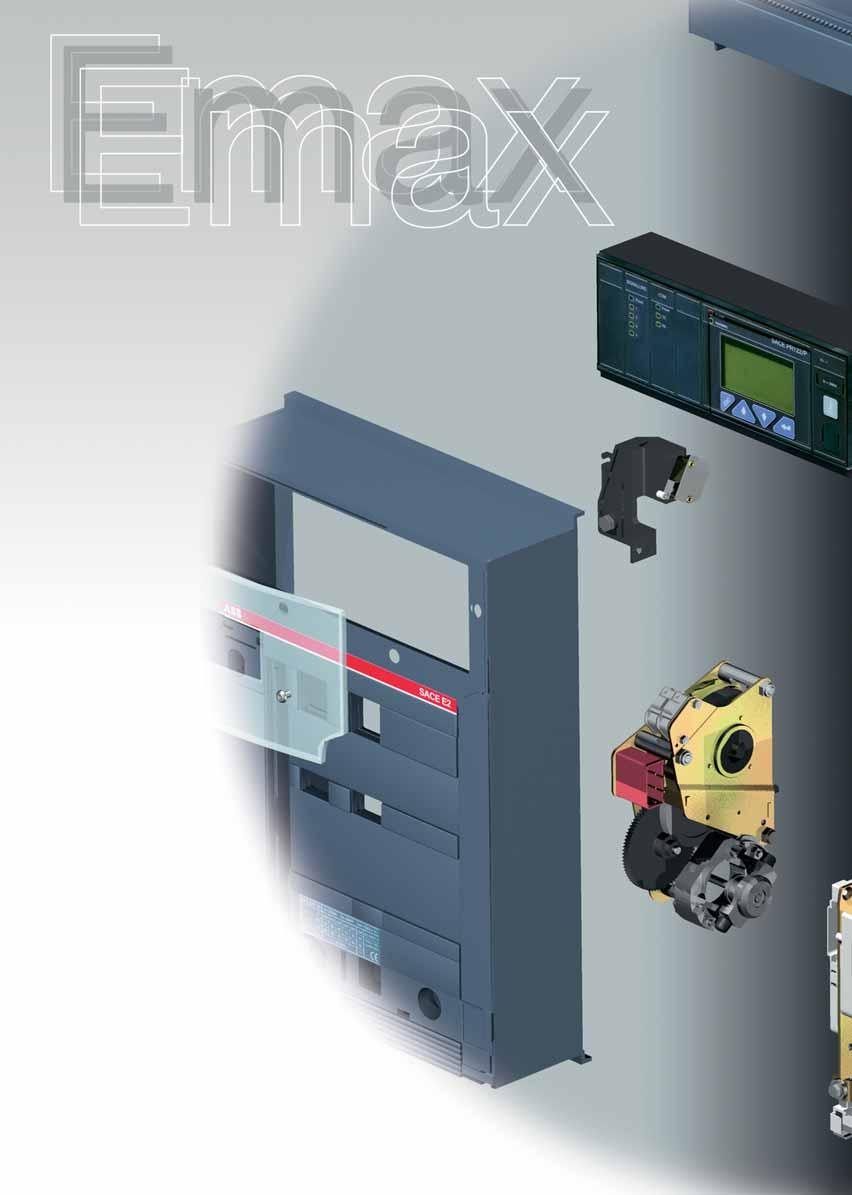
104

105 Accessories Contents Functions of the accessories... 5/2 Accessories supplied as standard... 5/3 Accessories supplied on request... 5/4 Shunt opening and closing releases... 5/6 Undervoltage release... 5/8 Geared motor for the automatic charging of closing springs... 5/10 Signalling of overcurrent releases tripped... 5/11 Auxiliary contacts... 5/12 Transformers and operation counters... 5/15 5 Mechanical safety locks... 5/16 Transparent protective covers... 5/18 Interlock between circuit-breakers... 5/19 Automatic transfer switch - ATS /22 Spare parts and Retrofitting... 5/25 ABB SACE 5/1
106 Functions of the accessories The table below lists a few functions that can be obtained by selecting the appropriate accessories from among those provided. Several of the functions listed may be needed at the same time, depending on how the circuit-breaker is used. See the relative section for a detailed description of the individual accessories. Function Components Remote control Opening release Closing release Geared motor for automatic charging of the closing springs Remote signalling or actuation of automatic functions depending on the state (open-closed-tripped) or position (racked-in, test isolated, racked-out) of the circuit-breaker. Circuit-breaker open-closed auxiliary contacts Circuit-breaker racked-in, test isolated, racked-out auxiliary contacts (withdrawable circuit-breaker only) Contact for electrical signalling of overcurrent releases tripped Contact for signalling undervoltage release de-energized Contact for signalling springs charged Remote opening for various needs, including: manual emergency control opening dependent on tripping of other interruption devices or system automation needs (1). Opening or undervoltage release 5 Automatic opening of the circuit-breaker for undervoltage (for example, when operating asynchronous motors) Instantaneous or time delay undervoltage release (2) Contact for signalling undervoltage release energized Increased degree of protection IP54 door protection Mechanical safety locks for maintenance or functional requirements for interlocking two or more circuit-breakers Key lock in open position Padlock device in open position Key lock and padlocks in racked-in, test isolated, racked-out position Automatic switching of power supplies Mechanical interlock between two or three circuit-breakers Automatic transfer switch - ATS010 (1) Examples: circuit-breakers on Low Voltage side of parallel transformers that must open automatically when the Medium Voltage side device opens. automatic opening for control by external relay (undervoltage, residual current, etc.). (2) The time-delay device is recommended when unwanted operation due to temporary voltage drops, is to be avoided (for functional or safety reasons). 5/2 ABB SACE
107 Accessories supplied as standard The following standard accessories are supplied depending on the circuit-breaker version: Note: (*) Not supplied with the switch disconnector. Fixed circuit-breaker: flange for switchgear compartment door (IP30) support for service releases four auxiliary contacts for electrical signalling of circuit-breaker open/closed (for automatic circuit-breakers only) terminal box for connecting outgoing auxiliaries mechanical signalling of overcurrent release tripped (*) horizontal rear terminals lifting plate Note: (*) Not supplied with the switch disconnector. Withdrawable circuit-breaker: flange for switchgear compartment door support for service releases four auxiliary contacts for electrical signalling of circuit-breaker open/closed (for automatic circuit-breakers only) sliding contacts for connecting outgoing auxiliaries mechanical signalling of overcurrent release tripped (*) horizontal rear terminals anti-insertion lock for circuit-breakers with different rated currents racking-out crank handle lifting plate 5 ABB SACE 5/3
108 Accessories supplied on request The ranges Automatic circuit-breakers Circuit-breakers with full-size neutral Circuit-breakers for applications up to 1150V AC 5 Circuit-breaker version Fixed Withdrawable 1a) Shunt opening/closing release (YO/YC) and second opening release (YO2) 1b) SOR test unit 2a) Undervoltage release (YU) 2b) Time-delay device for undervoltage release (D) 3) Geared motor for the automatic charging of the closing springs (M) 4a) Electrical signalling of electronic releases tripped 4b) Electrical signalling of electronic releases tripped with remote reset command 5a) Electrical signalling of circuit-breaker open/closed (1) 5b) External supplementary electrical signalling of circuit-breaker open/closed 5c) Electrical signalling of circuit-breaker racked-in/test isolated/racked-out 5d) Contact signalling closing springs charged 5e) Contact signalling undervoltage release de-energized (C. Aux YU) 6a) Current transformer for neutral conductor outside circuit-breaker 6b) Homopolar toroid for the main power supply earthing conductor (star center of the transformer) 6c) Homopolar toroid for residual current protection 7) Mechanical operation counter 8a) Lock in open position: key 8b) Lock in open position: padlocks 8c) Circuit-breaker lock in racked-in/racked-out/test isolated position 8d) Accessories for lock in racked-out/test isolated position 8e) Accessory for shutter padlock device 8f) Mechanical lock for compartment door 9a) Protection for opening and closing pushbuttons 9b) IP54 door protection 10) Interlock between circuit-breakers (2) 11) Automatic transfer switch - ATS010 (3) n n n n n n n n n n n n n n n n n n n n n n n n n n n n n n n n n n n n n n n n n n n n n n n n CAPTION Accessory on request for fixed circuit-breaker or moving part Accessory on request for fixed part Accessory on request for moving part n n n 5/4 ABB SACE
109 Switch-disconnectors Switch-disconnectors for applications up to 1150V AC Switch-disconnectors for applications up to 1000V DC Isolating truck (CS) Earthing switch with making capacity (T) Earthing truck (MT) Fixed Withdrawable Withdrawable Withdrawable Withdrawable n n n (YC) n n n n n n n n n n n n n n n n n n n n n n n n n n n n n n n n n n n n n n n n n n n n n n n n n n n n n n n n n n 5 (1) For automatic circuit-breakers, four auxiliary contacts to electrically signal circuit-breaker open/closed are included in the supply as standard. (2) Incompatible with the E6/f versions with full-size neutral (3) Incompatible with the range of circuit-breakers for applications up to 1150V AC ABB SACE 5/5
110 Shunt opening and closing releases (1) The minimum impulse current duration time in instantaneous service must be 100 ms (2) If the opening release is permanently connected to the power supply, wait at least 30 ms before sending the command to the shunt closing release. 1SDC200131F0001 1a) Shunt opening and closing release (YO/YC) and second opening release (YO2) Allows remote control opening or closing of the apparatus, depending on the installation position and connection of the releases on the support. The release can, in fact, be used for either of these two applications. Given the characteristics of the circuit-breaker operating mechanism, opening (with the circuit-breaker closed) is always possible, whereas closing is only possible when the closing springs are charged. The release can operate with direct current or alternating current. This release provides instantaneous operation (1), but can be powered permanently (2). Some installations require very high safety in controlling circuit-breaker opening remotely. In particular, the control and opening release circuits must be duplicated. To meet these needs, SACE Emax circuit-breakers can be equipped with a second shunt opening release, fitted with a special support to hold it, that can house the standard shunt closing and opening releases. The seat of the second shunt opening release is that of the undervoltage release, which is therefore incompatible with this type of installation. The special support, including the second shunt opening release, is installed in place of the standard support. The technical specifications of the second shunt opening release remain identical to those of the standard shunt opening release. When used as a permanently powered closing release, it is necessary to momentarily de-energize the shunt closing release in order to close the circuit-breaker again after opening (the circuit-breaker operating mechanism has an anti-pumping device). Reference figure in electrical circuit diagrams: YO (4) - YC (2) - YO2 (8) 5 1SDC200132F0001 1SDC200133F0001 1SDC200134F0001 Characteristics Power supply (Un): 24 V DC V AC/DC 30 V AC/DC V AC/DC 48 V AC/DC V AC/DC 60 V AC/DC V AC V AC/DC 440 AC Operating limits: (YO-YO2): 70% % Un (IEC EN Standards) (YC): 85% % Un Inrush power (Ps): DC = 200 W Inrush time ~100 ms AC = 200 VA Continuous power (Pc): DC = 5 W AC = 5 VA Opening time (YO- YO2): (max) 60 ms Closing time (YC): (max) 80 ms Insulation voltage: 2500 V 50 Hz (for 1 min) 5/6 ABB SACE

111 1SDC200135F0001 1b) SOR Test Unit The SOR control and monitoring Test Unit helps ensure that the various versions of SACE Emax opening releases are running smoothly, to guarantee a high level of reliability in controlling circuit-breaker opening. Under particularly severe operating conditions or simply for remote control of the circuit-breaker, the opening release is widely used as an accessory for the SACE Emax series of air circuitbreakers. Keeping all the functions of this accessory is a necessary condition to guarantee a high level of safety in the installation: it is therefore necessary to have a device available which cyclically checks correct operation of the release, signalling any malfunctions. The SOR control and monitoring Test Unit ensures the continuity of opening releases with a rated operating voltage between 24 V and 250 V (AC and DC), as well as the functions of the opening coil electronic circuit are verified. Continuity is checked cyclically with an interval of 20s between tests. The unit has optic signals via LEDs on the front, which provide the following information in particular: POWER ON: power supply present YO TESTING: test in progress TEST FAILED: signal following a failed test or lack of auxiliary power supply ALARM: signal given following three failed tests. Two relays with one change-over are also available on board the unit, which allow remote signalling of the following two events: failure of a test - resetting takes place automatically when the alarm stops ) failure of three tests - resetting occurs only by pressing the manual RESET on the front of the unit) There is also a manual RESET button on the front of the unit. Reference figure in electrical circuit diagrams: AY (61) 5 Characteristics Auxiliary power supply Maximum interrupted current Maximum interrupted voltage 24 V V AC/DC 6 A 250V AC ABB SACE 5/7
112 Undervoltage release 1SDC200136F0001 2a) Undervoltage release (YU) The undervoltage release opens the circuit-breaker when there is a significant voltage drop or power failure. It can be used for remote release (using normally-closed pushbuttons), for a lock on closing or for monitoring the voltage in the primary and secondary circuits. The power supply for the release is therefore obtained on the supply side of the circuit-breaker or from an independent source. The circuit-breaker can only be closed when the release is powered (closing is mechanically locked). The release can operate with direct current or alternating current. The circuit-breaker is opened with release power supply voltages of 35-70% Un. The circuit-breaker can be closed with a release power supply voltage of % Un. It can be fitted with a contact to signal when the undervoltage release is energized (C. aux YU) (see accessory 5e). Reference figure in electrical circuit diagrams: YU (6) 5 Characteristics Power supply (Un): 24 V DC V AC/DC 30 V AC/DC V AC/DC 48 V AC/DC V AC 60 V AC/DC V AC V AC/DC 440 V AC Operating limits: CEI EN Standards Inrush power (Ps): DC = 200 W AC = 200 VA Continuous power (Pc): DC = 5 W AC = 5 VA Opening time (YU): 30 ms Insulation voltage: 2500 V 50 Hz (for 1 min) 1SDC200137F0001 5/8 ABB SACE
113 1SDC200138F0001 2b) Time-delay device for undervoltage release (D) The undervoltage release can be combined with an electronic time-delay device for installation outside the circuit-breaker, allowing delayed release tripping with adjustable preset times. Use of the delayed undervoltage release is recommended to prevent tripping when the power supply network for the release is subject to brief voltage drops or power supply failures. Circuit-breaker closing is inhibited when it is not powered. The time-delay device must be used with an undervoltage release with the same voltage. Reference figure in electrical circuit diagrams: YU +D (7) Characteristics Power supply (D): Adjustable opening time (YU+D): V DC 48 V AC/DC 60 V AC/DC V AC/DC V AC/DC s 5 ABB SACE 5/9

114 Geared motor for the automatic charging of the closing springs 3) Geared motor for the automatic charging of the closing springs (M) This automatically charges the closing springs of the circuitbreaker operating mechanism. After circuit-breaker closing, the geared motor immediately recharges the closing springs. The closing springs can, however, be charged manually (using the relative operating mechanism lever) in the event of a power supply failure or during maintenance work. It is always supplied with a limit contact and microswitch for signalling that the closing springs are charged (see accessory 5d). 1SDC200139F0001 Reference figure in electrical circuit diagrams: M (1) 5 Characteristics Power supply Operating limits: Inrush power (Ps): Rated power (Pn): Inrush time Charging time: Insulation voltage: V AC/DC V AC/DC V AC/DC V AC/DC 85%...110% Un (CEI EN Standards) DC = 500 W AC = 500 VA DC = 200 W AC = 200 VA 0.2 s 4-5 s 2500 V 50 Hz (for 1 min) 1SDC200140F0001 5/10 ABB SACE
115 Signal for overcurrent releases tripped 4) Electrical signalling of electronic releases tripped The following signals are available after the electronic release has tripped: 4a) Electrical signalling of electronic releases tripped This allows visual signalling on the operating mechanism (mechanical) and remote signalling (electrical using switch) that the circuit-breaker is open following operation of the overcurrent releases. The mechanical signalling pushbutton must be rearmed to reset the circuit-breaker. Reference figure in electrical circuit diagrams: S51 (13) 5 1SDC200144F0001 1SDC200141F0001 4b) Electrical signalling of electronic releases tripped with remote reset command This allows visual signalling on the operating mechanism (mechanical) and remote signalling (electrical using switch) that the circuit-breaker is open following operation of the overcurrent releases. With this accessory, it is possible to reset the mechanical signalling pushbutton via an electrical coil from a remote command, which also allows the circuit-breaker to be reset. Available reset coils V AC/DC V AC/DC V AC/DC Reference figure in electrical circuit diagrams: S51 (14) ABB SACE 5/11
116 Auxiliary Contacts 5) Auxiliary contacts Auxiliary contacts are available installed on the circuit-breaker, which enable signalling of the circuit-breaker status. The auxiliary contacts are also available in a special version for application with rated voltages Un < 24 V (digital signals). Characteristics Un In max T 125 V DC 0.3 A 10 ms 250 V DC 0.15 A Un In max cosj 250 V AC 5 A 0,3 The versions available are as follows: 5 1SDC200145F0001 5a-5b) Electrical signalling of circuit-breaker open/closed It is possible to have electrical signalling of the status (open/ closed) of the circuit-breaker using 4, 10 or 15 auxiliary contacts. The auxiliary contacts have the following configurations: 4 open/closed contacts for PR121 (2 normally open + 2 normally closed) 4 open/closed contacts for PR122/PR123 (2 normally open + 2 normally closed + 2 dedicated to release) 10 open/closed contacts for PR121 (5 normally open + 5 normally closed) 10 open/closed contacts for PR122/PR123 (5 normally open + 5 normally closed + 2 dedicated to release) 15 supplementary open/closed contacts for installation outside the circuit-breaker. The basic configuration described above can be modified by the user for normally open or normally closed indication by repositioning the faston connector on the microswitch. When 10 open/closed contacts for PR122/PR123 are required, the zone selectivity and PR120/K unit are not available. Reference figure in electrical circuit diagrams: Q/1 10 (21-22) 1SDC200146F0001 5/12 ABB SACE
117 5c) Electrical signalling of circuit-breaker racked-in/test isolated/racked out 1SDC200147F0001 In addition to mechanical signalling of the circuit-breaker position, it is also possible to obtain electrical signalling using 5 or 10 auxiliary contacts which are installed on the fixed part. It is only available for withdrawable circuit-breakers, for installation on the fixed part. The auxiliary contacts take on the following configurations: 5 contacts; set comprising 2 contacts for racked-in signal, 2 contacts for racked-out signal, and 1 contact to signal the test isolated position (main pliers isolated, but sliding contacts connected). 10 contacts; set comprising 4 contacts for racked-in signal, 4 contacts for racked-out signal, and 2 contacts to signal the test isolated position (main pliers isolated, but sliding contacts connected). Reference figure in electrical circuit diagrams: S75I (31-32) S75T (31-32) S75E (31-32) 5 1SDC200148F0001 ABB SACE 5/13
.")
118 Auxiliary Contacts 5d) Contact for signalling closing springs charged This is made up of a microswitch which allows remote signalling of the state of the circuit-breaker operating mechanism closing springs (always supplied with the spring charging geared motor). 1SDC200149F0001 Reference figure in electrical circuit diagrams: S33 M/2 (11) 1SDC200150F e) Contact signalling undervoltage release de-energized (C.aux YU) The undervoltage releases can be fitted with a contact (normally closed or open, as preferred) for signalling undervoltage release energized, to remotely signal the state of the undervoltage release. 1SDC200151F0001 Reference figure in electrical circuit diagrams: (12) 1SDC200152F0001 5/14 ABB SACE

")
, the In of the same toroid can be set at 100 A, 250 A, 400 A, 800 A.")
119 Transformers and operation counters 6a) Current sensor for neutral conductor outside circuit-breaker For three-pole circuit-breakers only, this allows protection of the neutral by connecting it to the overcurrent release. Supplied on request. 1SDC200153F0001 Reference figure in electrical circuit diagrams: UI/N (page 8/8) 1SDC200154F0001 6b) Homopolar toroid for the main power supply earthing conductor (star centre of the transformer) SACE PR122 and PR123 electronic releases can be used in combination with an external toroid located on the conductor, which connects the star centre of the MV/LV transformer (homopolar transformer) to earth. In this case, the earth protection is defined as Source Ground Return. Through two different combinations of connection of its terminals (see chapter 8), the In of the same toroid can be set at 100 A, 250 A, 400 A, 800 A. 6c) Homopolar toroid for residual current protection SACE PR122/P LSIRc, PR122/P LSIG (with PR120/V) and PR123/P may be also used in combination with this accessory, enabling residual current protection. Rc protection can be activated only if the special rating plug for residual current protection ad the external toroid are present. Characteristics Rated current 3-30A 5 7) Mechanical operation counter This is connected to the operating mechanism by means of a simple lever mechanism, and indicates the number of mechanical operations carried out by the circuit-breaker. The count is shown on the front of the circuit-breaker. 1SDC200156F0001 1SDC200155F0001 ABB SACE 5/15
: a special circular lock with different keys (for a single circuit-breaker) or the same keys (for several circuit-breakers).")
120 Mechanical safety locks 1SDC200157F0001 8) Mechanical safety locks 8a-8b) Lock in open position Several different mechanisms are available which allow the circuit-breaker to be locked in the open position. These devices can be controlled by: Key (8a): a special circular lock with different keys (for a single circuit-breaker) or the same keys (for several circuit-breakers). In the latter case, up to four different key numbers are available. Padlocks (8b): up to 3 padlocks (not supplied): ø 4 mm. 1SDC200159F0001 1SDC200158F SDC200160F0001 8c) Circuit-breaker lock in racked-in/test isolated/rackedout position This device can be controlled by a special circular key lock with different keys (for a single circuit-breaker) or the same keys (for several circuit-breakers - up to four different key numbers available) and padlocks (up to 3 padlocks, not supplied - Ø 4 mm). It is only available for withdrawable circuit-breakers, to be installed on the moving part. 1SDC200161F0001 8d) Accessories for lock in test isolated/racked-out position 1SDC200162F0001 In addition to the circuit-breaker lock in the racked-in/test isolated/racked-out position, this only allows the circuit-breaker to be locked in the racked-out or test isolated positions. It is only available for withdrawable circuit-breakers, to be installed on the moving part. 5/16 ABB SACE

121 8e) Accessory for shutter padlock device 1SDC200163F0001 This allows the shutters (installed on the fixed part) to be padlocked in their closed position. It is only available for withdrawable circuit-breakers, to be installed on the fixed part. 1SDC200164F0001 8f) Mechanical lock for compartment door This stops the compartment door from being opened when the circuit-breaker is closed (and circuit-breaker racked in for withdrawable circuit-breakers) and prevents the circuit-breaker from being closed when the compartment door is open. 5 1SDC200165F0001 ABB SACE 5/17

122 Transparent protective covers 1SDC200166F0001 9) Transparent protective covers 9a) Protective cover for opening and closing pushbuttons These protections are fitted over the opening and closing pushbuttons, preventing the relative circuit-breaker operations unless a special tool is used. 1SDC200167F0001 9b) IP54 door protection 5 This is a transparent plastic protective cover which completely protects the front panel of the circuit-breaker, with a protection rating of IP54. Mounted on hinges, it is fitted with a key lock. 1SDC200169F0001 1SDC200168F0001 5/18 ABB SACE
 using a flexible cable. The circuit diagram for electrical switching using a relay (to be installed by the customer) is supplied with the mechanical interlock.")
123 Interlock between circuit-breakers 1SDC200170F ) Mechanical interlock This mechanism creates a mechanical interlock between two or three circuit-breakers (even different models and different versions, fixed/withdrawable) using a flexible cable. The circuit diagram for electrical switching using a relay (to be installed by the customer) is supplied with the mechanical interlock. The circuit-breakers can be installed vertically or horizontally. Four types of mechanical interlocks are available: Type A: between 2 circuit-breakers (power supply + emergency power supply) Type B: between 3 circuit-breakers (2 power supplies + emergency power supply) Type C: between 3 circuit-breakers (2 power supplies + bus-tie) Type D: between 3 circuit-breakers (3 power supplies / one single closed CB) Note: See the Overall dimensions and Electrical circuit diagrams chapters for information about dimensions (fixed and withdrawable versions) and settings. 5 1SDC200171F0001 1SDC200172F0001 Vertical interlock Horizontal interlock ABB SACE 5/19
124 Interlock between circuit-breakers The mechanical interlocks possible are shown below, depending on whether 2 or 3 circuit-breakers (any model and in any version) are used in the switching system. Type of interlock Typical circuit Possible interlocks Type A Between two circuit-breakers One normal power supply and one emergency power supply G Circuit-breaker 1 can only be closed if 2 is open, and vice-versa. 1 2 O O 1 2 I O O I O = Circuit-breaker open I = Circuit-breaker closed Type B Between three circuit-breakers Two normal power supplies and one emergency power supply. G Circuit-breakers 1 and 3 can only be closed if 2 is open. Circuit-breaker 2 can only be closed if 1 and 3 are open O O O I O O O O I I O I O = Circuit-breaker open O I O I = Circuit-breaker closed 5 Type C Between three circuit-breakers The two half-busbars can be powered by a single transformer (bus-tie closed) or by both at the same time (bus-tie open) One or two circuitbreakers out of three can be closed at the same time O O O I O O O I O O O I O = Circuit-breaker open I = Circuit-breaker closed O I I I I O I O I Type D Between three circuit-breakers Three power supplies (generators or transformers) on the same busbar, so parallel operation is not allowed G Only one of three circuit-breakers can be closed O O O I O O O I O O O I O = Circuit-breaker open I = Circuit-breaker closed 5/20 ABB SACE
125 The emergency power supply is usually provided to take over from the normal power supply in two instances: to power health and safety services (e.g. hospital installations); to power parts of installations which are essential for requirements other than safety (e.g. continuous cycle industrial plants). The range of accessories for SACE Emax circuit-breakers includes solutions for a wide variety of different plant engineering requirements. See the specific regulations regarding protections against overcurrents, direct and indirect contacts, and provisions to improve the reliability and safety of emergency circuits. Switching from the normal to the emergency power supply can either be carried out manually (locally or by remote control) or automatically. To this end, the circuit-breakers used for switching must be fitted with the accessories required to allow electric remote control and provide the electrical and mechanical interlocks required by the switching logic. These include: the shunt opening release the shunt closing release the motor operator the auxiliary contacts. Switching can be automated by means of a special electronically-controlled relay circuit, installed by the customer (diagrams provided by ABB SACE). Mechanical interlocks between two or three circuit-breakers are made by using cables which can be used both for circuit-breakers side by side or superimposed. 5 ABB SACE 5/21

126 Automatic transfer switch - ATS SDC200177F ) Automatic transfer switch - ATS010 The ATS010 switching unit (Automatic transfer switch) is the new network-generator switching device offered by ABB SACE. It is based on electronic technology conforming with the major electromagnetic compatibility and environmental Standards (EN 50178, EN , EN , IEC , IEC , IEC ). The device is able to manage the entire switching procedure between the normal and emergency line circuit-breakers automatically, allowing great flexibility of adjustment. In case of an anomaly in the normal line voltage, in accordance with the delays set, the normal line circuit-breaker is opened, the generator started and the emergency line circuit-breaker closed. Similarly, when the normal line returns, the reverse switching procedure is automatically controlled. It is especially suitable for use in all emergency power supply systems requiring a solution that is ready to install, easy to use and reliable. Some of the main applications include: power supply for UPS (Uninterrupted Power Supply) units, operating rooms and primary hospital services, emergency power supply for civilian buildings, airports, hotels, data banks and telecommunications systems and power supply of industrial lines for continuous processes. The switching system consists of the ATS010 unit connected to two motor-driven and mechanically interlocked circuit-breakers. All the circuit-breakers in the SACE Emax series can be used. The network sensor built into the SACE ATS010 device makes it possible to detect errors in the network voltage. The three inputs can be directly connected to the three phases of the normal power supply line for networks with rated voltage up to 500V AC. Networks with a higher voltage require insertion of voltage transformers (TV), setting a rated voltage for the device that matches their secondary voltage (typically 100V). Two changeover contacts for each circuit-breaker allow direct connection to the shunt opening and closing releases. The circuit-breaker connection is completed by wiring the status contacts: Open/Closed, Release tripped, Racked-in (for withdrawable/plug-in circuit-breakers). That is why the following are included on every circuit-breaker connected to the ATS010 unit, in addition to the mechanical interlock accessories: spring charging motor, opening and closing coil, open/closed contact, racked-in contact (for withdrawable versions), signal and mechanical lock for protection release tripped. The ATS010 device is designed to ensure extremely high reliability for the system it controls. It contains various safety systems intrinsically related to software and hardware operation. For software safety, a special logic prevents unwarranted operations, while a constantly operational watchdog system signals any microprocessor malfunctions via a LED on the front of the device. Hardware safety allows integration of an electrical interlock via a power relay, so that there is no need to use an external electrical interlock system. The manual selector on the front of the device can also control the entire switching procedure, even in the event of a microprocessor fault, by working electromechanically on the control releases. 5/22 ABB SACE
127 General specifications Rated supply voltage 24V DC ± 20% 48V DC ± 10% (galvanically insulated from earth) (maximum ripple ± 5%) Maximum power consumption 5W at 24V DC 10W at 48V DC Rated power (network present and circuit-breakers not controlled) 1.8W a 24V DC 4.5W at 48V DC Operating temperature -25 C +70 C Maximum humidity 90% without condensation Storage temperature -25 C +80 C Degree of protection IP54 (front panel) Dimensions [mm] 144 x 144 x 85 Weight [kg] 0.8 Setting range for thresholds and times Minimum voltage Un Min -5% -30% Un Maximum voltage Un Max +5% +30% Un Fixed frequency thresholds 10% +10% fn t1: opening delay of the normal line circuit-breaker due to network anomaly (CB-N) 0 32s t2: generator start-up delay due to network anomaly 0 32s t3: stopping delay of the generator 0 254s t4: switching delay due to network re-entry 0 254s t5: closing delay of the emergency line circuit-breaker after detecting the generator voltage (CB-E) 0 32s Rated voltages settings available 100, 115, 120, 208, 220, 230, 240, 277, 347, 380, 400, 415, 440, 480, 500 V 5 Operating sequence VN CB-N GE VE t2 t1 t3 Caption VN Network voltage CB-N Normal line circuit-breaker closed GE Generator VE Emergency line voltage CoCo Enabling switching to emergency line CB-E Emergency line circuit-breaker closed LOAD Disconnection of lower priority loads CoCo CB-E LOAD t5 t4 ABB SACE 5/23
128 Automatic transfer switch - ATS010 Front panel SDC200178F Caption 1 Status of the ATS010 unit and logic 2 Operating mode selector 3 Normal line check 4 Normal line circuit-breaker status 5 Voltage present on the emergency line 6 Emergency line circuit-breaker status 7 Generator status 5 Side panel settings SDC200179F0001 Caption 1 Selectors to adjust the undervoltage and overvoltage thresholds 2 Dip-switches for adjustment: rated voltage normal single-phase or three-phase line network frequency switching strategy 3 Switching delay time settings for t1... t5 5/24 ABB SACE
129 Spare parts and retrofitting Spare parts The following spare parts are available: front metal shields and escutcheon plate opening solenoid for PR121, PR122 and PR123 overcurrent release arcing chamber closing springs jaw-type isolating contact for the fixed part of the withdrawable circuit-breaker earthing sliding contact (for withdrawable version) shutters for fixed part complete pole operating mechanism connection cables for releases and current sensors transparent protective cover for releases SACE PR030/B power supply unit toolbox battery for SACE PR030/B power supply unit front escutcheon plate for Ronis key lock For further details, please request a copy of the ABB SACE spare parts catalogue. Retrofitting Kits Special kits have been prepared to replace old SACE Otomax and SACE Novomax G30 circuitbreakers. The kits include SACE Emax circuit-breakers that take advantage of all the components of the existing switchgear. Installing a new circuit-breaker in old switchgear, offers definite technical and economic benefits, and is extremely rapid as there is no need to redo the main switchgear connections. 5 ABB SACE 5/25

130

131 Applications of the circuit-breaker Contents Primary and secondary distribution Selective protection... 6/2 Back-up protection... 6/13 Directional protection... 6/14 Earth fault protection... 6/20 Switching and protection of transformers... 6/26 Line protection... 6/30 Switching and protection of generators... 6/32 Switching and protection of asynchronous motors... 6/35 Switching and protection of capacitors... 6/41 6 ABB SACE 6/1
132 Primary and secondary distribution Selective protection Selectivity is normally actuated for tripping overcurrent protection devices in civil and industrial installations to isolate the part affected by a fault from the system, causing only the circuit-breaker immediately on the supply side of the fault to trip. The example in the figure highlights the need to coordinate tripping between the two circuit-breakers A and B so that only circuit-breaker B is tripped in the event of a fault in C, ensuring continuity of service for the rest of the system supplied by circuit-breaker A. Whereas natural selectivity within the overload current range is normally found due to the difference between the rated currents of the load protection circuit-breaker and the main circuit-breaker on the supply side, selectivity can be obtained in the shortcircuit current range by differentiating the current values and, if necessary, the trip times. Circuit diagram with selective coordination of protections 1SDC200181F0001 Selectivity can be total or partial: total selectivity: only circuit-breaker B opens for all current values lesser than or equal to the maximum short-circuit current in C; partial selectivity: only circuit-breaker B opens for fault currents below a certain value; A and B are both tripped for greater or equal values. In principle, the following types of selectivity are possible: Current selectivity, obtained by setting the instantaneous trip currents of the circuitbreaker chain to different values (higher settings for the circuit-breakers on the supply side). This often results in partial selectivity. 6 Example of current-type selectivity 1SDC200182F0001 Time selectivity, obtained by intentionally incorporating increasing time-delays in the trip times of the circuit-breakers furthest to the supply side in the chain. Example of time-type selectivity 1SDC200183F0001 6/2 ABB SACE
133 To guarantee selectivity for Emax circuit-breakers, equipped with electronic PR121, PR122 and PR123 type releases, the following conditions must be verified: that there is no intersection between the time-current curves of the two circuit-breakers, tolerances included the minimum difference between the trip time t 2 of the circuit-breaker on the supply side and the time t 2 of the circuitbreaker on the load side, whenever it is an Emax circuitbreaker, must be: - t 2 supply side > t 2 load side ms* t = cost - t 2 supply side > t 2 load side ms i²t = cost (<400 ms) - t 2 supply side > t 2 load side ms i²t = cost (>400 ms) * in auxiliary power supply or in self-supply at full power, it is reduced to 70ms. When the above conditions are met: if function I is active (I 3 =on), the maximum short-circuit current guaranteeing selectivity is equal to the setting value I 3 (minus the tolerances) if function I is disabled (I 3 =off), the maximum short-circuit current for which selectivity is guaranteed must be equal to: - the value indicated in the table on page 6/12, if the circuitbreaker on the load side is a moulded-case circuit-breaker (MCCB) - the minimum value between the I cw of the circuit-breaker on the supply side and the I cu of the circuit-breaker on the load side, when both the circuit-breakers are Emax type. 6 ABB SACE 6/3
134 Primary and secondary distribution Selective protection Here is an example of total selectivity between three Emax circuit-breakers in series in a system with 415 V rated voltage and 70 ka prospective short-circuit current. Ik = 70kA@415V Circuit-breaker B E3S 3200 PR122-LSI In 3200 Circuit-breaker A E6H 6300 PR122-LSI In Time-Current Curve Circuit-breaker C E2S 1250 PR122-LSI In 1250 Circuit-breakers L S (t=cost) I Name Type Icu@415V Icw I1 t1 I2 t2 I3 A E6H ka 100 ka ,25 off B E3S ka 75 ka ,15 off C E2S ka 65 ka ,05 off As shown in the figure below, with the above-mentioned setting there is no intersection between the time-current curves of the different circuit-breakers and the minimum delay of 70 ms defined for the trip thresholds of protection S. Furthermore, exclusion of protection I (I 3 =off) guarantees selectivity as follows: up to 75 ka between A and B up to 75 ka between B and C. So, since the maximum prospective short-circuit current of the system is 70 ka, it is possible to talk of total selectivity. 1SDC200185F0001 1SDC200312F0001 6/4 ABB SACE
135 Double S Thanks to the new PR123 release, which allows two thresholds of protection function S to be set independently and be activated simultaneously, selectivity can also be achieved under highly critical conditions. Here is an example of how, by using the new release, it is possible to obtain a better selectivity level compared with the use of a release without double S. This is the wiring diagram of the system under examination; in particular, attention must be focussed on: the presence, on the supply side, of a MV circuit-breaker, which, for selectivity reasons, imposes low setting values for the Emax circuit-breaker on the LV side the presence of a MV/LV transformer which, due to the inrush currents, imposes high setting values for the circuit-breakers on its primary side. MV CB MV/LV Transformer 6 Ik=22.6kA LV/LV Transformer 1SDC200313F0001 ABB SACE 6/5
136 Primary and secondary distribution Selective protection Solution with a release without double S LV/LV Trans. 315kVA Time-Current 400V 1SDC200314F0001 MV CB (PR521) 50 (I>): 50 A t=0.5s 51 (I>>): 500 A t=0s 6 E2N 1250 PR122 T5V 630 PR222DS/P LSIG R1250 LSIG R630 L Setting Curve 108s 12s S t=constant Setting Curve 0.5s 0.25s I Setting OFF 7 In the case of a short-circuit, the Emax E2 circuit-breaker and the MV circuit-breaker will open simultaneously with this solution. Attention must be paid to the fact that, owing to the value Ik, function I of the E2 circuit-breaker has to be disabled (I 3 =OFF) so that selectivity with the T5 on the load side is granted. 6/6 ABB SACE
137 Solution with the PR123 release with double S LV/LV Trans. 315kVA Time-Current 400V 1SDC200315F0001 MV CB (PR521) 50 (I>): 50 A t=0.5s 51 (I>>): 500 A t=0s E2N 1250 PR123 T5V 630 PR222DS/P LSIG R1250 LSIG R630 L Setting Curve 108s 12s S t=constant Setting Curve s S1 t=constant Setting Curve 0.5s - S2 t=constant Setting 5 - Curve 0.05s - I Setting OFF 7 6 As is evident, by means of the double S function, selectivity can be achieved both with the T5 circuit-breaker on the load side as well as with the MV circuit-breaker on the supply side. A further advantage obtained by using the double S function is the reduction in the time of permanence of high current values under short-circuit conditions, which results in lower thermal and dynamic stresses on the busbars and on the other installation components. ABB SACE 6/7
138 Primary and secondary distribution Selective protection Dual Setting 6 Thanks to the new PR123 release, it is also possible to program two different sets of parameters and, through an external command, to switch from one set to the other. This function is useful when there is an emergency source (generator) in the system, only supplying voltage in the case of a power loss on the network side. non-priority loads In the system described below, in the case of a loss of the normal supply on the network side, by means of the ABB SACE ATS010 automatic transfer switch, it is possible to switch the supply from the network to the emergency power unit and to disconnect the non-primary loads by opening the QS1 switchdisconnector. Under normal service conditions of the installation, the circuit-breakers C are set in order to be selective with both circuit-breaker A, on the supply side, as well as with circuitbreakers D on the load side. By switching from the network to the emergency power unit, circuit-breaker B becomes the reference circuit-breaker on the supply side of circuitbreakers C. This circuitbreaker, being the protection of a generator, must be set to trip times shorter than A and therefore the setting values of the circuit-breakers on the load side might not guarantee the selectivity with B. By means of the dual setting function of the PR123 release, it is possible to switch circuitbreakers C from a parameter set which guarantees selectivity with A, to another set which make them selective with B. However, these new settings could make the combination between circuit-breakers C and the circuit-breakers on the load side non-selective. 1SDC200316F0001 6/8 ABB SACE
139 The figure at the side shows the time-current curves of the installation under normal service conditions. The values set allow no intersection of the curves. Time current curves 1SDC200317F0001 The figure at the side shows the situation in which, after switching, the power is supplied by the power unit through circuit-breaker B. If the settings of circuit-breakers C are not modified, there will be no selectivity with the main circuitbreaker B. Time current curves 1SDC200318F0001 This last figure shows how it is possible to switch to a set of parameters which guarantees selectivity of circuit-breakers C with B by means of the dual setting function. 6 Time current curves 1SDC200319F0001 ABB SACE 6/9
140 Primary and secondary distribution Selective protection Zone selectivity The zone selectivity, which is applicable to protection functions S and G, can be enabled in the case where the curve with fixed time is selected and the auxiliary power supply is present. This type of selectivity allows shorter trip times for the circuitbreaker closest to the fault than in the case of time-selectivity. It is a type of selectivity suitable for radial nets. The word zone is used to refer to the part of an installation between two circuit-breakers in series. The fault zone is the zone immediately on the load side of the circuit-breaker that detects the fault. Each circuit-breaker that detects a fault communicates this to the circuit-breaker on the supply side by using a simple communication wire. The circuit-breaker that does not receive any communication from those on the load side will launch the opening command within the set selectivity time (40 200ms). We have to consider that the circuit-breakers receiving a signal from another release will operate according to the set time t2. If, for any reason, after the selectivity time, the circuit-breaker due to trip has not opened yet, it lets the block signal fall on the other circuit-breaker, which will trip. To realize correctly the zone selectivity the following settings are suggested: S t2 ³ selectivity time + t opening * I I3 = OFF G t4 ³ selectivity time + t opening * Selectivity time same setting for each circuit-breaker * Trip duration for I < Icw (max) = 70 ms. 6 6/10 ABB SACE
141 To carry out the cabling, a shielded twisted pair cable (not supplied; ask ABB for information) can be used. The shield should only be earthed on the release of the circuit-breaker on the supply side. The maximum length of the cabling for zone selectivity, between two units, is 300 meters. The maximum number of the circuit-breakers which can be connected to the outputs (Z out) of a release is 3. The maximum numbers of the circuit-breakers which can be connected to the inputs (Z in) of a release is 20. All Emax circuit-breakers in versions B-N-S-H-V fitted with PR122 and PR123 releases allow zone selectivity to be realised. Note With regard to selectivity in the case of earth faults with circuit-breakers in series, see page 6/20. Zone 3 Zone 2 Zone 1 1SDC200186F ABB SACE 6/11
142 Primary and secondary distribution Selective protection Selectivity tables 6 Emax air circuit-breakers with moulded-case circuit-breakers Supply-side E1 E2 E3 E4 E6 Version B N B N S L* N S H V L* S H V H V Release EL EL EL EL EL Load-side Version Release Iu [A] B T T T T T T T T T T T T T T T T T1 C TM 160 T T T T T T T T T T T T T T T T N T T T T T T T T T T T T T T T T N T T T T T T T T T T T T T T T T T2 S 36 T T T T T T T T T T T T T T T TM, EL 160 H 36 T T T T T T T T T T T T T L 36 T T T T T 75 T T T T T T T T3 N T T T T T T T T T T T T T T T T TM 250 S 36 T T T T T T T T T T T T T T T N T T T T T T T T T T T T T T T T T4 S 36 T T T T T T T T T T T T T T T 250 H TM, EL 36 T T T T T T T T T T T T T 320 L 36 T T T T T T 100 T 100 V 36 T T T T T T 100 T 100 N T T T T T T T T T T T T T T T T T5 S 36 T T T T T T T T T T T T T T T 400 H TM, EL 36 T T T T T T T T T T T T T 630 L 36 T T T T T T 100 T 100 V 36 T T T T T T 100 T 100 N T T T T T T T T T T T T T T T T S6 S 36 T T T T T T T T T T T T T T T TM, EL 800 H 36 T T 55 T T T T T T T T T T T T L 36 T T T T T T T T T T T S7 S T T T T T T T T T T T T T 1250 H EL T 55 T T T T T T T T T T T 1600 L T T T T T T T T T General prescriptions: Function I of the electronic PR121, PR122 and PR123 releases of the supply-side circuit-breakers must be excluded in OFF). (I3 Selectivity is expressed in ka at the supply voltage of V AC in accordance with IEC Standards. T = total selectivity (the selectivity value is the lowest one between the breaking capacities (Icu) of both the circuit-breaker on the loadside as well of the circuit-breaker on the supply side) It is of fundamental importance to verify that the settings chosen by the user for the releases placed both on the supply as well as on the load side do not result in intersections of the time-current curves for protection against overload (function L) and for protection against short-circuit with time-delayed trip (function S). * Emax L circuit-breakers with PR122/P and PR123/P releases only. 6/12 ABB SACE
143 Primary and secondary distribution Back-up protection Back-up protection is required by the IEC Standards and Annex A of the IEC Standard, which allow the use of a protection device with breaking capacity lower than the prospective short-circuit current at the points where it is installed, provided that there is another protection device on the supply side with the necessary breaking capacity. In this case, the characteristics of the two devices must be coordinated in such a way that the specific energy let through by the combination is not higher than that which can be withstood without damage by the device on the load side, and by the protected conductors. In the diagram in the figure, circuit-breaker B, located on the load side of circuit-breaker A, can have a lower breaking capacity than the prospective short-circuit current in the event of a fault in C, if circuit-breaker A is able to satisfy both of the following conditions: it has a suitable breaking capacity (higher than or equal to the prospective short-circuit current at its point of installation and obviously higher than the short-circuit current in C ) in the event of a fault in C with short-circuit values higher than the breaking capacity of circuit-breaker B, circuitbreaker A must provide a specific let-through energy limiting function, limiting it to a value that can be withstood by circuit-breaker B and by the protected conductors. A fault in C can therefore cause a double interruption, however the back-up protection must ensure that B always trips within the limits of its breaking capacity. It is necessary to choose switchgear combinations that have been verified by laboratory tests for this type of protection. The possible combinations are specified in ABB SACE documents and PC programs (Slide rule kits, DOCWin, etc.) and shown here for SACE Emax circuit-breakers. Back-up protection is used in electrical installations in which there is no essential need for continuous operation: when the supply-side circuit-breaker opens, it also excludes loads that are not affected by the fault. Furthermore, the use of this type of coordination limits the size of the installation and consequently reduces costs. Note Back-up protection can also be implemented on more than two levels: the figure above shows an example of coordination on three levels. In this case, the choices are correct if at least one of the two situations below is satisfied: the circuit-breaker furthest on the supply side A is coordinated with both circuitbreakers B and C (coordination between circuit-breakers B and C is not necessary); each circuit-breaker is coordinated with the circuit-breaker immediately to the load side of it, i.e. the circuit-breaker furthest to the supply side A is coordinated with the next one B, which is in turn coordinated with circuit-breaker C. 1SDC200187F0001 1SDC200188F Table showing coordination for back-up protection Supply-side circuit-breaker Breaking capacity E2L - E3L 130 [ka] (at 380/415 V) Load-side circuit-breaker Back-up value T4N 65 [ka T4S - T5N - S6N - E1B - E2B 85 [ka] T4H - T5S/H - S6S/H - S7S/H - E1N - E2N 100 [ka] T4L - T5L 130 [ka] ABB SACE 6/13
144 Directional protection Directional protection is based on the ability to correlate the circuit-breaker s behavior with the direction of the fault current. Two different trip times can be set on the PR123 release depending on the current direction: a time (t7fw) for a direction of current concordant (Fw) with the reference direction set; a time (t7bw) for a direction of current discordant (Bw) with the reference direction set. A current threshold only (I7) can be set on the PR123 release. If the fault current is discordant (Bw) with the reference direction, the protection shall intervene when the threshold I7 is reached within the set time t7bw (provided that the functions S and I have not been set as to intervene before function D). If the fault current is concordant (Fw) with the reference direction, the protection shall intervene when the threshold I7 is reached within the set time t7fw (provided that the functions S and I have not been set as to intervene before function D). Moreover, if function I is active and the short-circuit current exceeds the set value I 3, the circuitbreaker will trip instantaneously independently of the direction of the current. The reference direction set by ABB is from the top of the circuit-breaker (the zone where the release is located) towards the bottom. G1 G2 Release Release Reference direction set by ABB Reference direction inverted through software Reference direction set by ABB 1SDC200189F The figure above shows the actual configuration the circuit-breakers have in the system. The red arrow shows the reference direction set by default on the circuit-breaker. If the power supply direction of the circuit-breaker is from top to bottom (supply from G2), the reference direction must remain the one set by ABB. If the power supply direction of the circuit-breaker is from bottom to top (supply from G1), the new PR123 release allows the default setting to be inverted by operating on its software. In this way, all the quantities measured by the PR123 release can be evaluated as they actually flow through the installation. Furthermore, in the wiring diagram of the system, the reference direction to carry out a selectivity Contribution to the study and consider the G1 short-circuit by each generator: G2 10 ka tripping directions Bw or Fw A correctly still remains from top QF1 with B QF2 with PR123 PR123 to bottom. In the following wiring diagram Reference Reference the reference directions direction I> direction I> are shown in red. By considering the circuit-breakers supplied C as in the figure above, it QF3 with QF4 can be seen that for QF2 this PR222 D E is the default direction, I> I> whereas for QF1 the direction has been inverted by means M of the software. Other passive loads Contribution of the motor to the short-circuit: 5 ka 1SDC200190F0001 6/14 ABB SACE
145 By assuming some numerical values for the short-circuit currents, and considering some fault points, the following is the result. For circuit breaker QF1, if a fault occurs at point B, the current will flow in direction A-B concordant to the reference direction or similarly, for a fault in A, the current direction will be B-A in discordance with the reference direction. The different configurations can be resumed in the following table: Circuit-breaker Location of fault Measured current [ka] Direction Tripping time QF1 QF2 A 15 Discordant t7bw B, C, D, E 10 Concordant t7fw B 15 Discordant t7bw A, C, D, E 10 Concordant t7fw This installation aims at selectivity between QF1, QF2, QF3 and QF4. On examining the table, we see that the only instance in which the fault current direction is discordant with that set for the circuit-breaker QF1 occurs in case of a fault in point A. The circuitbreaker QF1 must trip more quickly than the other circuit-breakers, since it is the one nearest to the fault. To this purpose, the trip time t7bw of QF1 must be set at: a value below the time t7fw of the circuit-breaker QF2, since the fault current is concordant with QF2 reference direction a value lower than the time t2 of protection S, if available, for the release of the moulded-case circuit-breaker QF4. The instantaneous protection of QF4 shall be set in OFF or shall have a setting value I3 higher of the contribution given by the motor to the short-circuit current. Moreover, the functions S and I of both QF1 and QF2 have been set so as not to intervene before function D. Similarly to the process described for circuit-breaker QF1, to ensure selectivity, circuit-breaker QF2 must trip first in the case of a fault in B, and then with a delayed trip in the case of faults anywhere else in the system. 6 The settings available for directional protection D, both for Fw and Bw, are the following: I 7 = xIn (tolerance + 10%) step 0.1xIn t 7 =0.20s...0.8s (tolerance + 20%) step 0.01s ABB SACE 6/15
146 Directional protection Zone selectivity D (Directional Zone Selectivity) Thanks to this function, it is also possible to obtain selectivity in meshed and ring networks. By means of zone selectivity with function D Zone selectivity D, which can only be set to [On] when zone selectivity S and G are set to [Off] and there is an auxiliary power supply, it is possible to coordinate the behaviour of the various PR123 devices, by cabling the release buses in a suitable way. In fact, each release has 4 signals available: two input signals (one in a concordant and one in a discordant direction) by means of which the release receives the block signal from other releases two output signals (one in a concordant and one in a discordant direction) by means of which the release sends a block signal to other releases. The circuit-breakers which do not receive a block signal (coordinated in the direction of the current) will send the opening command within a time equal to t 7 sel. The circuit-breakers which receive the block signal will open within the backward or forward time according to the direction of the current. If function I is activated and the short-circuit current exceeds the set value (I 3 ), the circuit-breaker will open instantaneously and independently of the directions and of the signals received. For safety reasons, the maximum duration of the block signal is 200ms. If, after this time and for any reason, the circuit-breakers due to trip have not yet opened, the block signal falls on the other circuit-breakers which will command immediate opening. This operation therefore occurs after a maximum time of 200ms. A shielded twisted pair cable (not supplied; ask ABB for information) can be used to carry out the cabling. The shield should only be earthed on the release of the circuit-breaker on the supply side. The maximum length of the cabling for zone direction selectivity, between two units, is 300 metres. A maximum number of 3 circuit-breakers can be connected to the outputs (OUT Bw or OUT Fw) of a release. A maximum number of 20 circuit-breakers can be connected to the inputs (IN Bw or IN Fw) of a release. 6 Direction (OUT-IN) Bw Þ Bw Bw Þ Fw Fw Þ Fw Reference Direction Arrow The figure below shows the connections necessary to activate the blocks between the various releases. In particular: 1) in the case of a fault in A, circuit-breaker QF1 is passed through by a current from busbar B1; this current flows in a direction discordant with the one set. The OUT Bw bus of QF1 blocks the IN Fw bus of circuit-breaker QF2 and the IN Bw bus of circuit-breaker QF3: in fact, the current flows through QF2 in the same direction as the setting, G1 G2 whereas QF3 is passed through by a current discordant A B with the setting (the ac- tive block signals are indicated by wider arrows). QF1 + PR123 I> IN Fw Bw OUT Fw Bw QF2 + PR123 I> IN Fw Bw OUT Fw Bw C B1 QF3 + PR123 I> IN Fw Bw OUT Fw Bw D M 1SDC200191F0001 6/16 ABB SACE
147 Direction (OUT-IN) Bw Þ Bw Bw Þ Fw Fw Þ Fw Reference Direction Arrow 2) in the case of a fault in B, circuit-breaker QF2 is passed through by a current from busbar B1; this current flows in a direction discordant with the one set. The OUT Bw bus of QF2 blocks the IN Fw bus of circuit-breaker QF1 and the IN Bw bus of circuit-breaker QF3: in fact, the current flows through QF1 in the same direction as the setting, G1 G2 whereas QF3 is passed A B through by a current discordant with the setting (the active block signals are indicated by wider arrows). I> I> QF1 + PR123 IN Fw Bw OUT Fw Bw QF2 + PR123 IN Fw Bw OUT Fw Bw C B1 QF3 + PR123 I> IN Fw Bw OUT Fw Bw D M 1SDC200192F0001 Direction (OUT-IN) Bw Þ Bw Bw Þ Fw Fw Þ Fw Reference Direction Arrow 3) in case of a fault in C, circuit-breakers QF1 and QF2 are passed through by a current flowing in the same direction as the one set, whereas QF3 is passed through by a current with discordant direction. No circuitbreaker is blocked and consequently G1 G2 all the circuit-break- A B ers affected by the fault will trip according to the time settings of protections S and/ QF1 + QF2 + PR123 I> PR123 I> or I. IN Fw Bw OUT Fw Bw IN Fw Bw OUT Fw Bw 6 C B1 QF3 + PR123 I> IN Fw Bw OUT Fw Bw D M 1SDC200193F0001 ABB SACE 6/17
148 Directional protection Direction (OUT-IN) Bw Þ Bw Bw Þ Fw Fw Þ Fw Reference Direction Arrow 4) in the case of a fault in D, circuit-breaker QF3 is passed through by a current from busbar B1; this current flows in the same direction as the one set. The OUT Fw bus of QF3 blocks the IN Fw bus of circuit-breakers G1 G2 QF1 and QF2: in fact, both circuit-breakers are passed A B through by fault currents concordant with the direction set (the active block signals are I> I> indicated by wider arrows). QF1 + PR123 IN Fw Bw OUT Fw Bw QF2 + PR123 IN Fw Bw OUT Fw Bw C B1 QF3 + PR123 I> IN Fw Bw OUT Fw Bw D M 1SDC200194F0001 The following example analyses a network with a bus-tie and takes the behavior of the protection devices in the presence of faults into consideration: 6 Direction (OUT-IN) Fw Þ Fw Fw Þ Bw Bw Þ Fw Reference Direction Arrow 1) Fault in B1 with the bus-tie closed: only circuit-breakers QF1 and QF3 must interrupt the fault: in particular, circuit-breaker QF3 is passed through by a current from busbar B2 (therefore in the same direction as the one set); the OUT Fw bus sends a block signal to the IN Fw bus of circuitbreaker QF2 (passed through by a current flowing from transformer TM2 and consequently -TM1 Ik A QF1 + QF2 + -TM2 in a direction concordant with the one set), and to the IN Bw IN PR123 IN PR123 IN bus of circuit-breaker QF5 -B1 -B2 I> OUT OUT OUT Fw Fw Bw Bw Fw Fw Bw Bw Fw Fw Bw Bw I> I> (passed through from a current flowing from the motor and consequently in a direction discordant with the one set). IN Fw Bw OUT Fw Bw I> QF4 + PR123 QF3 + PR123 QF5 + PR123 I> IN Fw Bw OUT Fw Bw L M 1SDC200320F0001 6/18 ABB SACE
149 Direction (OUT-IN) Fw Þ Fw Fw Þ Bw Bw Þ Bw Bw Þ Fw Reference Direction Arrow 2) Fault in the motor: in this case, only circuit-breaker QF5 must interrupt the fault. Circuit-breaker QF5 is passed through by a current flowing from busbars B1 and B2, in a direction concordant with the one set; therefore, the OUT Fw bus of QF5 blocks both the IN Fw bus of QF2 (passed through by a current flowing from TM2 and consequently in a direction concordant with the one set) as well as the IN Bw bus of QF3 (which is passed through by a current flowing from TM1 and consequently in a direction discordant with the one set). Similarly, circuit-breaker QF3 is also passed through by a current flowing from TM1 in a direction -TM1 Ik -TM2 discordant with the one set: consequently, the OUT A QF1 + QF2 + Bw bus of QF3 blocks the IN PR123 IN PR123 IN Fw Bw Fw Bw Fw Bw IN Fw bus of QF1 (passed OUT OUT OUT Fw Bw Fw Bw Fw Bw through by a current flowing I> I> from TM1 and therefore in a -B1 I> -B2 direction concordant with the setting). IN Fw Bw OUT Fw Bw I> QF4 + PR123 QF3 + PR123 QF5 + PR123 I> IN Fw Bw OUT Fw Bw L M 1SDC200321F0001 Direction (OUT-IN) Fw Þ Fw Fw Þ Bw Bw Þ Bw Bw Þ Fw Reference Direction Arrow 3) Fault on the supply side of transformer TM2: in this case, only circuit-breaker QF2 must interrupt the fault. Circuit-breaker QF2 is passed through by a current flowing from TM1 and from the motor, in a direction discordant with the one set; as a consequence the OUT Bw bus of QF2 blocks : the IN Bw bus of QF5 (passed through by a current flowing from the motor and consequently in a direction discordant with the one set) the IN Bw bus of QF3 (passed through by a current flowing from TM1 and consequently in a direction discordant with the one set). Similarly, circuit-breaker QF3 -B1 IN Fw Bw OUT Fw Bw IN Fw Bw OUT Fw Bw A I> I> -TM1 Ik QF1 + PR123 QF4 + PR123 IN Fw Bw OUT Fw Bw I> QF2 + PR123 QF3 + PR123 QF5 + PR123 I> I> -TM2 IN Fw Bw OUT Fw Bw IN Fw Bw OUT Fw Bw -B2 is also passed through by a current flowing from TM1 in a direction discordant with the one set; therefore its OUT Bw bus blocks the IN Fw bus of QF1 (passed through by a current flowing from TM1 and therefore in a direction concordant with the one set). 6 L M 1SDC200322F0001 ABB SACE 6/19
150 Earth fault protection Circuit-breakers with protection G Circuit-breakers fitted with re- Protection function G calcu- regard to the protection de- leases offering earth fault pro- lates the vectorial sum of the vices installed on the load side. tection function G are usually currents detected by the cur- Selectivity is therefore ensured used in MV/LV distribution sub- rent transformers on the regarding the residual-current stations to protect both the phases and on the neutral con- releases located on the load transformers and the distribu- ductor. In a sound circuit, this side. tion lines. sum, which is called residual Function G of the PR121, current, is equal to zero, PR122 and PR123 releases is whereas in the presence of an provided with specific let- TT L1 L2 L3 N earth fault it has a value depending on the fault ring involved. Function G is effectively used through energy curves (I²t=k) and with independent timecurrent curves (t=k). The figure in the following page massa P 1SDC200195F0001 in TT, IT, and TN-S electrical installations and, limited to the section of the installation with a neutral conductor (N) branched and separated from shows an example of one possible choice of earth fault protection devices and their possible settings. Protection functions G of the the conductor PE, in TN-CS circuit-breakers on the main TN-C L1 L2 L3 PEN systems as well (for the TN-S area only). Function G is not used in TN- C systems, since these provide the neutral and protection switchboard A serve to enable them to trip selectively, in relation to each other and to the residual-current protection devices located on the loads of the functions using a single con- distribution switchboard B. massa 1SDC200196F0001 ductor. The protection device thresholds and trip times can be selected from a wide range, also making it easy to achieve se- 6 TN-S L1 L2 L3 N PE lectivity for this type of fault with absence of fault fault trip within t 4 I d =I L1 + I L2 + I L3 +I N =0 I d =I L1 + I L2 + I L3 +I N ¹ 0 I d ³ I 4 massa 1SDC200197F0001 IT L1 L2 L3 Z PE 1SDC200198F0001 6/20 ABB SACE
151 Example of selection of earth fault protection devices and their relevant settings. Switchboard A 1600 kva 20 / 0,4 kv E3N25 with PR122 In = 2500 A I4 = 0.25 x In = 625 A t4 = 0.8 s (t=k) E1N12 with PR121 In = 1000 A I4 = 0.2 x In = 200 A t4 = 0.4 s (t = k) Switchboard B T4N320 with RC222 In = 320 A T2N160 with RC221 In = 100 A I Dn = 5 ma t Dn = 0.2 s I Dn = 0.1 ma t Dn = 0 s 1SDC200199F ABB SACE 6/21
152 Earth fault protection Use of the toroid on the star center of the transformer In the case of circuit-breakers to protect MV/LV transformers, it is possible to install a toroid on the conductor connecting the star centre of the transformer to earth (application allowed with the SACE Emax series fitted with the PR122 and PR123 electronic releases. This detects the earth fault current. The figure beside shows the operating principle of the toroid installed on the star centre of the transformer. The use of this accessory allows the protection threshold against earth fault (function G) to be independent of the size of the primary current transformers installed on the circuit-breaker phases. For the technical characteristics of the toroid see the table at page 6/24. PR122 - PR123 1SDC200200F Double G The Emax type circuit-breakers, equipped with the PR123 electronic release, allow two independent curves for protection G: one for the internal protection (function G without external toroid) and one for the external protection (function G with external toroid, as described in the above paragraph). A typical application of function double G consists in simultaneous protection both against earth fault of the secondary of the transformer and of its connection cables to the circuit-breaker terminals (restricted earth fault protection), as well as against earth faults on the load side of the circuit-breaker (outside the restricted earth fault protection). Example Figure 1 shows a fault on the load side of an Emax circuitbreaker: the fault current flows through one phase only and, if the vectorial sum of the currents detected by the four current transformers (CTs) is to be higher than the set threshold, the electronic release activates function G (and the circuitbreaker trips). External toroid Transformer secondary winding Emax Internal CTs Figure 1 1SDC200323F0001 6/22 ABB SACE
153 With the same configuration, a fault on the supply side of the circuit-breaker (Figure 2) does not cause intervention of function G since the fault current does not affect either the CT Transformer secondary winding of the phase or that of the neutral. Emax Internal CTs Figure 2 1SDC200324F0001 The use of function double G allows installation of an external toroid, as shown in Figure 3, so that earth faults on the supply side of Emax CB can be detected as well. In this case, the Transformer secondary winding alarm contact of the second G is exploited in order to trip the circuit-breaker installed on the primary and to ensure fault disconnection. Emax Internal CTs 6 External toroid Figure 3 1SDC200325F0001 ABB SACE 6/23
154 Earth fault protection If, with the same configuration as Figure 3, the fault occurs on the load side of the Emax circuit-breaker, the fault current would affect both the toroid as well as the current transformers on the phases. To define which circuit-breaker is to trip (MV or LV circuit-breaker), suitable coordination of the trip times is required: in particular, it is necessary to set the times so that the LV circuit-breaker opening due to internal function G is faster than realization of the alarm signal coming from the external toroid. Therefore, thanks to the time-current discrimination between the two G protection functions, before the MV circuit-breaker on the primary of the transformer receives the trip command, the circuit-breaker on the LV side is able to eliminate the earth fault. Obviously, if the fault occurred on the supply side of the LV circuit-breaker, only the circuit-breaker on the MV side would trip. The table shows the main characteristics of the range of toroids (available only in the closed version). Characteristics of the toroid ranges Rated current Outer dimensions of the toroid H D W up to 2000 A D = 400 mm W = 198 mm H = 51 mm 6 Residual current protection Emax air circuit-breakers can be equipped with a toroid fitted on the back of the circuit-breaker so as to ensure protection against earth faults. In particular, the electronic release types able to perform this function are: PR122/P L S I - Rc PR122/P L S I - G - with Measuring module PR123/P L S I G which can all be provided for the following types of circuitbreakers: E2 and E3, both three and four pole versions, and E4 (three pole version). Thanks to the wide range of settings, the above mentioned electronic releases with the residual current function are suitable for applications where a residual current protection system coordinated with the various distribution levels is to be constructed from the main switchboards to the final load. It is particularly suitable where low-sensitivity residual current protection is required, for example in both partial (current-type) or total (time-type) selectivity chains, and for high-sensitivity applications to protect people against indirect contact. These electronic releases with residual current protection are suitable for use in the presence of: alternating earth current (Type AC) alternating and/or pulsating current with continuous components (Type A) The table below shows the main technical characteristics of the residual current protection: Sensitivity I Dn [A] (dip in position 1) Tripping time [s] Type AC and A 6/24 ABB SACE
155 Using the SACE RCQ switchboard electronic residual current relays The family of SACE Emax circuit-breakers with a rated current up to 2000A can be combined, if fitted with a shunt opening release, with the SACE RCQ residual current relay for switchboard with a separate toroidal transformer (for installation outside on the line conductors) thereby enabling earth leakage currents to be determined for values between 0.03 and 30A. Thanks to the wide range of settings, the SACE RCQ switchboard relay is suitable for applications where a residual current protection system coordinated with the various distribution levels is to be constructed from the main switchgear to the final load. It is particularly suitable, for example, where low-sensitivity SACE RCQ residual current switchboard relay residual current protection is Power supply voltage AC [V] required in both partial (current-type) and total (time-type) Tripping threshold setting IDn DC [V] selective chains, and for highsensitivity applications to pro- Trip time settings 1 a range [s] a setting range [A] a setting range [A] tect people against indirect Trip time settings 2 a range [s] contact. Range of use of closed transformers - Toroidal transformer Æ 60mm [A] When the auxiliary power supply voltage drops, the opening Range of use of transformers that can be opened - Toroidal transformer Æ 110mm [A] command intervenes after a - Toroidal transformer Æ 110mm [A] minimum time of 100ms and - Toroidal transformer Æ180mm [A] Toroidal transformer Æ 230mm [A] after the time set above Dimensions (Dx H x W) [mm] 96 x 96 x ms. Drilling for assembly on door [mm] 92 x 92 The SACE RCQ relay is only suitable for use in the presence of alternating earth current (Type AC), for alternating and/ or pulsating current with continuous components (Type A), and is suitable for achieving residual current selectivity. The SACE RCQ relay acts indirectly, and works on the release mechanism of the circuit-breaker by means of the circuit-breaker shunt opening release (to be ordered by the customer) to be housed in the circuit-breaker itself. The table below shows the main characteristics of the SACE RCQ relay. 6 Dimensions of the external toroid for SACE RCQ Outer dimensions of the toroid Closed Openable D [mm] H W [mm] D W H [mm] Internal diameter Ø [mm] ABB SACE 6/25
156 Switching and protection of transformers General information When choosing circuit-breakers to protect the LV side of MV/LV transformers, the following must basically be taken into account:: the rated current of the protected transformer on the LV side, on which the circuit-breaker capacity and protection settings both depend; the maximum short-circuit current at the point of installation, which determines the minimum breaking capacity that must be offered by the protection device. MV-LV substation with a single transformer The rated current of the transformer, LV side, is determined by the following equation Sn Sn x 103 In = U 20 3 x U 20 where Sn = rated power of the transformer, in kva U20 ln = rated secondary voltage (no load) of the transformer, in V = rated current of the transformer, LV side, in A (rms value) The three-phase short-circuit current at full voltage, right at the LV terminals of the transformer, can be expressed by the following equation (assuming infinite short-circuit power at the primary): Ik In 1SDC200202F0001 Ik = In x 100 Uk% 6 where: Uk % = short-circuit voltage of the transformer, in % ln = rated current, LV side, in A (rms value) lk = rated three-phase short-circuit current, LV side, in A (rms value) If the circuit-breaker is installed some distance away from the transformer by using a cable or a bus duct connection, the shortcircuit current decreases, as a function of the impedance of the connection, in comparison with the values obtained by the equation above. In practice, the short-circuit value provided by the transformer is also affected by the short-circuit power of the Sk network to which the transformer is connected. 6/26 ABB SACE
157 MV-LV substation with multiple transformers in parallel The rated current of the transformer is calculated following the same procedure outlined in the previous section. The minimum breaking capacity of each protection circuitbreaker on the LV side must be higher than the highest of the following values (the example is for machine 1 in the figure and applies to three machines in parallel): Ik1 (short-circuit current of transformer 1) in the event of a fault immediately on the load side of circuit-breaker QF1; Ik2 + Ik3 (Ik2 and Ik3 = short-circuit currents of transformers 2 and 3) in the event of a short-circuit on the supply side of circuit-breaker QF1. Circuit-breakers QF4 and QF5 on the outgoing feeders must have a breaking capacity higher than Ik1 + Ik2 + Ik3; the contribution to the short-circuit current by each transformer obviously depends on the short-circuit power of the network to which it is connected, and on the line connecting the transformer and the circuit-breaker (to be determined on a case-by-case basis). 1SDC200203F0001 Ik2 + Ik3 QF1 Ik1 QF2 QF3 QF4 QF5 Ik1 + Ik2 + Ik3 Circuit-breaker A Circuit-breaker B 6 ABB SACE 6/27
158 Switching and protection of transformers Switching and protection of transformers Sk=750MVA Vn= 400V Transformer Circuit-breaker A Circuit-breaker B (LV side) (Feeder circuit-breaker) S r U k Transf Busbar Transf Type Release Busbar I r I b Feeder I k I k [kva] % [A] [A] [ka] size [ka] 800 A 1000 A 1250 A 1600 A 2000 A 2500 A 3200 A 4000 A 1x E1B 800 In= E1B08* 1x E1B 1000 In= E1B08* 1x E1B 1250 In= E1B08* 1x E1B 1600 In= E1B08* E1B10* E1B12* 1x E2B 2000 In= E1B08* E1B10* E1B12* E1B16* 1x E3N 2500 In= E1B08* E1B10* E1B12* E1B16* E2B20* 1x E3N 3200 In= E1N08* E1N10* E1N12* E1N16* E2N20* E3N25* 1x E4S 4000 In= E2N10* E2N10* E2N12* E2N16* E2N20* E3N25* E3N32* 1x E6H 5000 In= E2S08* E2S10* E2S12* E2S16* E2S20* E3S25* E3S32* E4S40 Transformer Circuit-breaker A Circuit-breaker B (LV side) (Feeder circuit-breaker) S r U k Transf Busbar Transf Type Release Busbar I r I b Feeder I k I k [kva] % [A] [A] [ka] size [ka] 800 A 1000 A 1250 A 1600 A 2000 A 2500 A 3200 A 4000 A 2x E1B 800 In= E1B08* 2x E1B 1000 In= E1N08* E1N10* E1N12* E1N16* 2x E1B 1250 In= E1N08* E1N10* E1N12* E1N16* E2N20* 2x E1B 1600 In= E2N10* E2N10* E2N12* E2N16* E2N20* E3N25* 2x E2B 2000 In= E2S08* E2S10* E2S12* E2S16* E2S20* E3S25* E3S32* 2x E3N 2500 In= E2S08* E2S10* E2S12* E2S16* E2S20* E3S25* E3S32* E4S40 2x E3N 3200 In= E3H08* E3H10* E3H12* E3H16* E3H20* E3H25* E3H32* E4H40 6 Transformer Circuit-breaker A Circuit-breaker B (LV side) (Feeder circuit-breaker) S r U k Transf Busbar Transf Type Release Busbar I r I b Feeder I k I k [kva] % [A] [A] [ka] size [ka] 800 A 1000 A 1250 A 1600 A 2000 A 2500 A 3200 A 4000 A 3x E1N 1000 In= E2N10* E2N10* E2N12* E2N16* E2N20* E3N25* 3x E1N 1250 In= E2N10* E2N10* E2N12* E2N16* E2N20* E3N25* 3x E2N 1600 In= E2S08* E2S10* E2S12* E2S16* E2S20* E3H25* E3H32* 3x E2S 2000 In= E3H08* E3H10* E3H12* E3H16* E3H20* E3H25* E3H32* E4H40 3x , E3S 2500 In= E3V08* E3V 12* E3V12* E3V16* E3V20* E3V25* E3V32* E4V40 WARNING! The table refers to the conditions specified on the previous page. The information for selecting the circuit-breakers is provided only in relation to the operating current and prospective short-circuit current. To make the correct selection, other factors such as selectivity, back-up protection, the decision to use current-limiting circuit-breakers, etc. have to be considered. It is therefore essential for designers to carry out precise verification. The types of circuit-breakers proposed are all from the SACE Emax series. Positions marked by an asterisk (*) are suitable for other possible selections from the Tmax or Isomax series of moulded-case circuit-breakers. One also needs to bear in mind that the short-circuit currents shown in the table have been calculated on the assumption of 750MVA power on the supply side of the transformers and without taking into account the impedances of the busbars and of the connections to the circuit-breakers. 6/28 ABB SACE
159 Switching and protection of transformers Sk=750MVA Vn= 690V Transformer Circuit-breaker A Circuit-breaker B (LV side) (Feeder circuit-breaker) S r U k Transf Busbar Transf Type Release Busbar I r I b Feeder I k I k [kva] % [A] [A] [ka] size [ka] 400A 630A 800 A 1000 A 1250 A 1600 A 2000 A 2500 A 3200 A 4000 A 1x E1B 800 In= E1B08* 1x E1B 800 In= E1B08* 1x E1B 800 In= E1B08* E1B08* 1x E1B 1000 In= E1B08* E1B08* E1B08* 1x E1B 1250 In= E1B08* E1B08* E1B08* 1x E1B 1600 In= E1B08* E1B08* E1B08* E1B10* E1B12* 1x E2B 2000 In= E1B08* E1B08* E1B08* E1B10* E1B12* E2B16* 1x E3N 2500 In= E1B08* E1B08* E1B08* E1B10* E1B12* E2B16* 1x E3N 3200 In= E2B16* E2B16* E2B16* E2B16* E2B16* E2B16* E2B20* Transformer Circuit-breaker A Circuit-breaker B (LV side) (Feeder circuit-breaker) S r U k Transf Busbar Transf Type Release Busbar I r I b Feeder I k I k [kva] % [A] [A] [ka] size [ka] 400A 630A 800 A 1000 A 1250 A 1600 A 2000 A 2500 A 3200 A 4000 A 2x E1B800 In= E1B08* E1B08* 2x E1B800 In= E1B08* E1B08* E1B08* 2x E1B800 In= E1B08* E1B08* E1B08* E1B10* 2x E1B1000 In= E1B08* E1B08* E1B08* E1B10* E1B12* 2x E1B1250 In= E2B16* E2B16* E2B16* E2B16* E2B16* E2B16* 2x E1B1600 In= E2B16* E2B16* E2B16* E2B16* E2B16* E2B16* E2B20* 2x E2B2000 In= E2N10*E2N10*E2N10*E2N10*E2N12*E2N16*E2N20*E3N25* Transformer Circuit-breaker A Circuit-breaker B (LV side) (Feeder circuit-breaker) S r U k Transf Busbar Transf Type Release Busbar I r I b Feeder I k I k [kva] % [A] [A] [ka] size [ka] 400A 630A 800 A 1000 A 1250 A 1600 A 2000 A 2500 A 3200 A 4000 A 3x E1B800 In= E2B16* E2B16* E2B16* E2B16* E2B16* 3x E1B800 In= E2B16* E2B16* E2B16* E2B16* E2B16* E2B16* 3x E1B1000 In= E2N10*E2N10*E2N10*E2N10*E2N12*E2N16*E2N20* 3x E2B1600 In= E2S08* E2S08* E2S08 E2S10* E2S12 E2S16 E2S20 E3N25 3x E2B1600 In= E2S08* E2S08* E2S08 E2S10* E2S12 E2S16 E2S20 E3N25 E3N32 3x E2N2000 In= E3S10* E3S10* E3S10* E3S10* E3S12 E3S16 E3S20 E3S25 E3S32 E4S40 6 WARNING! The table refers to the conditions specified on the previous page. The information for selecting the circuit-breakers is provided only in relation to the operating current and prospective short-circuit current. To make the correct selection, other factors such as selectivity, back-up protection, the decision to use current-limiting circuit-breakers, etc. have to be considered. It is therefore essential for designers to carry out precise verification. The types of circuit-breakers proposed are all from the SACE Emax series. Positions marked by an asterisk (*) are suitable for other possible selections from the Tmax or Isomax series of moulded-case circuit-breakers. One also needs to bear in mind that the short-circuit currents shown in the table have been calculated on the assumption of 750MVA power on the supply side of the transformers and without taking into account the impedances of the busbars and of the connections to the circuit-breakers. ABB SACE 6/29
160 Line protection The following main parameters must be known in order to make the correct choice of circuitbreakers for line operation and protection: operating current of the line l b permanent current-carrying capacity of the conductor l z section S and cable insulation material, with relative constant K short-circuit current I k at the point of installation of the circuit-breaker. The protection device selected must offer a breaking capacity (Icu or Ics at the system voltage) higher than or equal to the short-circuit value at the application point. The operating characteristics of the device selected must also meet the following conditions: Overload protection I b I n I z Note With regard to the verification required by the IEC Standards, which prescribe that the overload protection must have a trip current ensuring effective I2 operation of the device at a value lower than 1.45 < 1.45 Iz), this is always Iz (I2 satisfied since SACE Emax circuit-breakers comply with the CEI EN Standards and this value is 1.3 In. I f 1.45 I z where I b I z I n I f is the operating current of the circuit; is the permanent current-carrying capacity of the conductor; is the adjusted rated current of the protection device; is the current that ensures effective operation of the protection device. The above inequalities are easily respected thanks to the wide setting ranges offered by the PR121-PR122-PR123 releases. Short-circuit protection Assuming that a conductor overheats adiabatically during the passage of the short-circuit current, the following formula must be verified: (I 2 t) circuit-breaker (K 2 S 2 ) cable therefore the specific let-through energy (I 2 t) of the circuit-breaker must be lower than or equal to the specific let-through energy (K 2 S 2 ) withstood by the cable. 6 Also make sure that the circuit-breaker trips within the limits prescribed by the international standards regarding the minimum value of the short-circuit current at the end of the line. The minimum short-circuit current is the current which corresponds to a short-circuit occurring between phase and neutral (or between phase and phase if the neutral conductor is not distributed) at the farthest point of the conductor. Protection against indirect contacts In the event of a fault involving a phase and a part of the installation that is not normally live, it is best to make sure that the circuit-breaker trips within the times prescribed by the international standards for current values lower than or equal to the fault current. Based on the value of this current, it is possible to intervene using function I of the release, function G or, for extremely low values, the RCQ device A 0.5 A 30 A 50 A 375 A A RCQ Function G External toroid Residual current Function I 1SDC200204F0001 The figure shows which function of the electronic release or device to use on the basis of the fault current. 6/30 ABB SACE
161 Example: In an installation with Un=400V and Ik=45kA, a load with Ib=1102A is supplied with 4 cables in parallel, insulated in EPR of 300mm 2 and Iz=1193A With appropriate settings, the E2N2000 In=2000A circuit-breaker fitted with the PR122 electronic protection release, protects the cable in accordance with the above conditions, as illustrated in the following graphs. Time-Current Curve LLL IB=1102A Cable 300 mm 2 E2N 20 PR122 LSI In 2000 A 1SDC200205F0001 Specific let-through energy curve LLL Cable 300 mm 2 6 E2N 20 PR122 LSI In 2000 A 1SDC200206F0001 Note For protection against indirect contacts, it may be necessary to link the setting of the short-circuit protection to the length of the line protected. See the Slide rule kit and DOCwin software package for the calculation procedures required. Special attention must be paid to the selective coordination of circuit-breakers in series, to limit disservice in the event of faults to a minimum. ABB SACE 6/31
162 Switching and protection of generators Emax circuit-breakers are suitable for use with low-voltage generators employed in the following applications: A - back-up generators for primary loads B - generators disconnected from the supply network C - generators for small power stations connected in parallel with other generators and, possibly, with the power supply network. In cases A and B, the generator does not operate in parallel with the power supply network: the short-circuit current therefore depends on the generator itself and, possibly, on the connected loads. In case C, the breaking capacity must be determined by assessing the short-circuit current imposed by the network at the point of circuit-breaker installation. The main points to check for generator protection are: the short-circuit current delivered by the generator; this can only be assessed if one is familiar with the machine s typical reactance and time constants. Here one can simply note that low short-circuit protection device settings are normally required (2-4 times In); the thermal overload limit of the machine. According to the IEC Standard, this value is set at 1.5xIn for a period of 30 seconds. For a detailed assessment, see the DOCWin program or specialized books on the topic. The wide range of settings offered by electronic releases: PR121 Threshold I (1.5 to 15) x In Threshold S (1 to 10) x In PR122 Threshold I (1.5 to 15) x In Threshold S (0.6 to 10) x In PR123 Threshold I (1.5 to 15) x In Threshold S (0.6 to 10) x In makes SACE Emax circuit-breakers perfectly suitable for protecting large generators against short-circuit currents and against thermal overloads. 6 6/32 ABB SACE
163 Table for selecting circuit-breakers to protect generators The table shows the rated currents of the circuit-breakers, based on the electrical specifications of the generators. The breaking capacity required by the application must be defined in order to select the appropriate circuit-breaker. The electronic protection releases available are suitable for all requirements. Frequency 50 Hz - Voltage 400 V Frequency 60 Hz - Voltage 450 V Rated Rated Rated Rated Rated Rated power current current of the power current current of the of the generator of the generator circuit-breaker of the generator of the generator circuit-breaker [kva] [A] [A] [kva] [A] [A] ABB SACE 6/33
164 Switching and protection of generators Reverse power protection RP The reverse power protection is tripped when active power is incoming to the generator rather than outgoing as it is under normal conditions. Power reversal takes place if the mechanical power supplied by the main motor driving the generator drops sharply. In this condition, the generator acts as a motor, and can cause serious damage to the prime movers, such as overheating in steam turbines, cavitation in hydraulic turbines, or explosions of uncombusted diesel fuel in diesel engines. Outgoing Active Power Condition OK PR123 release not tripped Diesel Engine Gen PR123 Incoming Active Power Condition not OK PR123 release tripped 1SDC200207F0001 When the power measured by the release falls below zero, the PR123 release trips, opening the circuit-breaker and thereby preventing any damage. 6 6/34 ABB SACE
165 Switching and protection of asynchronous motors A low voltage automatic air circuit-breaker can, by itself, guarantee the following functions in power supply circuits of threephase asynchronous motors: switching overload protection short-circuit protection. 1SDC200208F0001 t [s] M A = Circuit-breaker B = Overload protection (inverse long time-delay trip) C = Short-circuit protection (instantaneous) M = Asynchronous motor Diagram showing direct starting of an asynchronous motor using just the circuit-breaker fitted with an electronic overcurrent release. I [A] Ie = Rated current of the motor Ia = Initial value of the transient starting current Ip = Maximum instantaneous value of the subtransient starting current ta = Starting time ts = Duration of subtransient phase 1SDC200209F0001 Trend of current values in the starting phase of a three-phase asynchronous motor. This solution is particularly suitable if the switching frequency is not high, as it is normally the case for large motors. In this case, using only the circuit-breaker for motor switching and protection represents a highly advantageous solution thanks to its competitive cost-efficiency, reliability, ease of installation and maintenance, and compact overall dimensions. The circuit-breakers in the SACE Emax selective (not currentlimiting) series are able to provide the motor switching and protection function by virtue of their high breaking capacities and the wide range of possible settings offered by the electronic releases. SACE Emax circuit-breakers are suitable for use with motors with rated powers within the range between 355 kw and 630 kw. For power ratings up to 355 kw, the moulded-case circuitbreakers in the SACE Isomax and Tmax range are also available. Medium voltage power supplies are normally used for powers above 630 kw. 6 ABB SACE 6/35
166 Switching and protection of asynchronous motors The switching of three-phase asynchronous motors demands considerable attention to the starting operation, since the current during this phase follows the typical behaviour shown in the figure, which must be taken into account when selecting the protection devices. It is essential to calculate the typical values of the times and currents indicated in the figure in order to select the correct switching and protection devices for the motor. These data are normally provided by the motor manufacturer. The following ratios generally apply: Ia = 6-10 Ie (Ia and Ie: rms values) Ip = 8-15 Ie (Ip and Ie: rms values). The protection releases must be adjusted so as to: prevent unwanted tripping ensure that the installation is protected against the overcurrents which might occur at any point on the load side of the circuit-breaker (including internal motor faults). The inverse long time-delay trip protection and instantaneous short-circuit protection must be set as close as possible to the motor starting curve without, however, interfering with it. Note The IEC Standard covers motor starters. The following classes are considered for overload protection: Operating Trip time t (s) for I = 7.2 x I1 class (I1 = release setting current) 10A 2 < t < t < t < t 30 6 The table specifies that the protection device must trip in a time t within the limits for its class when the current flowing through the device to be protected is 7.2 times the release setting current (assumed to be equal to the rated current of the motor). The overload devices are divided into classes in a manner closely linked to the motor starting time: for example, a motor with a starting time of 5 seconds requires a protection device in class 20. The same standards provide specific prescriptions for the protection device in cases of three-phase operation or with the loss of a phase. 6/36 ABB SACE
167 Warning The curves of the motor and releases are not directly comparable, since they both express time-current links, but have conceptually different meanings: the motor starting curve represents the values taken by the starting current instant by instant; the release curve represents the currents and corresponding trip times for the protection device. The overload trip curve is set correctly when it is immediately above point A (figure below), which identifies the top of the rectangle with sides formed by the starting time ta and the current Ia thermally equivalent to the variable starting current respectively. t [s] I [A] 1SDC200210F Three-phase operation The overload protection device at 1.05 times the setting current shall not trip in less than 2 hours starting from the cold state. When the current is 1.2 times the setting current, the tripping shall occur in less than 2 hours, as indicated in the table which follows (page 6/39) ABB SACE 6/37
168 Switching and protection of asynchronous motors Operation with the loss of a phase The IEC Standard prescribes that a release, with compensated temperature and sensitive to phase losses, must: not trip in less than two hours at 20 C, when one phase carries 90% of In and the other two carry 100% of In trip in less than two hours at 20 C, in the event of the loss of a phase when the current in the energized poles reaches 1.15 times the rated current In. With the PR122 and PR123 releases by activating the Unbalance function it is possible to check the losses of phase. Selecting the circuit-breakers to be used for motor protection The tables in the next pages show the rated characteristics for large motors, from 355 to 630 kw, with circuit-breakers in the SACE Emax series for switching and protecting motors in category AC-3 at 415/690 V - 50 Hz. The tables show the choice of current transformers able to ensure a sufficiently high value for the instantaneous trip threshold setting (I): in the absence of experimental data, it is advisable to verify that the ratio between the threshold of protection device I (I3) and the threshold of protection device L (I1) is: I3/I1 = The PR122 and PR123 electronic releases conform to the international IEC Standard. In particular, the devices ensure protection of class 10A, 10, 20 and 30 of motors. PR122 and PR123 protection releases are compensated in temperature, and their operation is not negatively affected by the loss of a phase. Advantages of earth fault protection G 6 The earth fault protection (G) is recommended in order to: improve safety against fire hazards improve protection of motors and personnel in the event of machine faults. Advantages of thermal memory The advisability of enabling the thermal memory (option offered by PR122 and PR123 releases) must be evaluated in relation to the type of load. Enabling the thermal memory (which makes the electronic protection similar to the one provided by a thermomagnetic device) increases the protection level of the motor when restarting after tripping due to an overload. Undervoltage protection The undervoltage protection device in control systems for asynchronous motors demands special attention, performing, amongst other things, two important functions: it prevents simultaneous restarting of all the motors on return of the power supply, with the risk of making the entire installation go out of service by tripping the main circuit-breaker overcurrent protection devices it prevents the motor from restarting without a control signal, which could be a hazard for maintenance personnel or could damage the processing cycle. 6/38 ABB SACE
169 This protection can be carried out by: undervoltage release, protection function UV (undervoltage) on the PR123 release. I/In Operating class Tp > 2h < 2h < 120 s 2 < t < 10s 10A < 240 s 4 < t < 10s 10 < 480 s 6 < t < 20s 20 < 720 s 9 < t < 30s 30 Direct On Line Normal Start-Up 415V 50Hz Motor SACE Emax circuit-breaker Electronic release Pe Ie Operations (AC-3) Type Icu Iu Type TA [kw] [A] [No.] [ka] [A] [A] E1B PR122/PR E1B PR122/PR E1B PR122/PR E1B PR122/PR E1B PR122/PR E1B PR122/PR E1B PR122/PR E1B PR122/PR E1B PR122/PR E1N PR122/PR E1N PR122/PR E1N PR122/PR E1N PR122/PR E1N PR122/PR E1N PR122/PR E1N PR122/PR E1N PR122/PR E1N PR122/PR E2N PR122/PR E2N PR122/PR E2N PR122/PR E2N PR122/PR E2N PR122/PR E2N PR122/PR E2N PR122/PR E2N PR122/PR E2N PR122/PR E3H PR122/PR E3H PR122/PR E3H PR122/PR E3H PR122/PR E3H PR122/PR E3H PR122/PR E3H PR122/PR E3H PR122/PR E3H PR122/PR ABB SACE 6/39
170 Switching and protection of asynchronous motors Direct On Line Normal Start-Up 690V 50Hz Motor SACE Emax circuit-breaker Electronic release Pe Ie Operations (AC-3) Type Icu Iu Type TA [kw] [A] [No.] [ka] [A] [A] E1B PR122/PR E1B PR122/PR E1B PR122/PR E1B PR122/PR E1B PR122/PR E1B PR122/PR E1B PR122/PR E1B PR122/PR E1B PR122/PR E2N PR122/PR E2N PR122/PR E2N PR122/PR E2N PR122/PR E2N PR122/PR E2N PR122/PR E2N PR122/PR E2N PR122/PR E2N PR122/PR E3S PR122/PR E3S PR122/PR E3S PR122/PR E3S PR122/PR E3S PR122/PR E3S PR122/PR E3S PR122/PR E3S PR122/PR E3S PR122/PR E3H PR122/PR E3H PR122/PR E3H PR122/PR E3H PR122/PR E3H PR122/PR E3H PR122/PR E3H PR122/PR E3H PR122/PR E3H PR122/PR /40 ABB SACE

171 Switching and protection of capacitors Operating conditions of circuit-breakers during continuous service for capacitor banks According to the IEC and Standards, capacitors must be able to operate in service conditions with a rated rms current of up to 1.3 times the rated current Icn of the capacitor. This prescription is due to the possible presence of harmonics in the mains voltage. It should also be kept in mind that a tolerance of +15% is admissible for the capacitance value corresponding to its rated power, so that the circuit-breakers for switching capacitor banks must be selected to permanently carry a maximum current equal to: ln = 1.3 x 1.15 x lnc = 1.5 x lnc. Current for connecting capacitor banks Connection of a capacitor bank can be compared to a closing operation under short-circuit conditions, where the transient making capacity Ip takes on high peak values, above all when capacitor banks are connected in parallel with others that are already powered. The value of Ip needs to be calculated for each individual situation because it depends on the individual circuit conditions and can in certain cases even have a peak value equal to x Icn for a duration of 1-2 ms. This fact must be taken into account when selecting the circuitbreaker, which must have a suitable making capacity, and when setting the overcurrent release, which must not cause unwanted trips when the bank is connected. Selecting the circuit-breaker Using the information on the rating plate of the three-phase capacitor bank Qn = rated power in kvar Un = rated voltage in V the rated current of the capacitor bank is determined as follows: 6 Inc = Qn x 10 3, in A. 3 x Un The following conditions must be verified for the circuit-breaker: Rated current ln > 1.5 lnc Overload protection setting l1 = 1.5 x lnc Short-circuit protection setting l3 = OFF Breaking capacity lcu > Ik, at the point of installation. ABB SACE 6/41

172 Switching and protection of capacitors Table for selecting the protection and switching circuit-breakers for capacitors The breaking capacity of the circuit-breaker must take into account the prospective short-circuit current at the point of installation. The available sizes are shown in the table. Rated current Rated current Overload Short-circuit Maximum power of the capacitor of the current of the capacitor protection protection bank at 50Hz [kvar] Circuit-breaker transformer bank setting setting 400V 440V 500V 690V Type In [A] Inc [A] I1 [A] I3 [A] E1 - E2 - E x In OFF E1 - E2 - E x In OFF E2 - E x In OFF E x In OFF E3 - E4 - E x In OFF Note The E2L and E2L circuit-breakers are not suitable for switching capacitor banks. 6 6/42 ABB SACE
173 ABB SACE 6/43 6
174

175 Overall dimensions Contents Fixed circuit-breaker... 7/2 Withdrawable circuit-breaker... 7/8 Mechanical interlock... 7/15 Circuit-breaker accessories... 7/16 7 ABB SACE 7/1
176 Overall dimensions Fixed circuit-breaker Basic version with horizontal rear terminals Y A A 4 POLES 5 B 3 POLES 80 E 440 min. 418 X F E X G Y C D 3 POLES 4 POLES Max Min 13 1SDC200212F0001 Caption 1 Inside edge of compartment door 2 Segregation (when provided) 3 M10 mounting holes for circuit-breaker (use M10 screws) 41xM12 screw (E1, E2, E3) or 2 x M12 screws (E4, E6) for earthing (included in the supply) E1/E2 View A 4 Y POLES POLES ø N M10 E3 View A M10 N Y POLES 3 POLES ø Insulating wall or insulated metal wall Max Max POLES POLES POLES POLES Y Y 1SDC200213F A B C D E F G E E E2 E E3 E E4/f E4/f E E6 E6/f /2 ABB SACE
177 E4 View A 66 4 Y POLES (E4) ø POLES (E4) 33 N POLES (E4/f) 66 N M Max Y 1SDC200214F0001 E6 View A Y POLES (E6) ø N POLES (E6) ø POLES (E6/f) ø13 18 N M10 3 Max Y 1SDC200215F0001 ABB SACE 7/3
178 Overall dimensions Fixed circuit-breaker Basic version with vertical rear terminals E1 E2/E4 E3/E6 A A A ø13 ø13 ø E1 View A E2 View A E3 View A N N M12 screws included in the supply N E4 E4/f E6 E6/f View A View A View A View A N N N M12 screws included in the supply N M12 screws included in the supply 1SDC200216F0001 7/4 ABB SACE
179 Version with front terminals E1 N ø E N ø13 E N ø13 1SDC200217F0001 ABB SACE 7/5
180 Overall dimensions Fixed circuit-breaker Version with front terminals E4 E4 E4/f N N ø ø13 E6 E6 E6/f N N 460 1SDC200218F ø ø13 7 7/6 ABB SACE
181 Compartment dimensions Drilling of compartment door Y ø ø X X B A 242 Min 282 Max 3 POLES 4 POLES Depth 2 holes for IP54 protective cover 100 R Y Through-holes for flexible cables for mechanical interlocks Tightening torque for main terminals Nm 70 Tightening torque for earthing screw Nm 70 High strength M12 screw Number per terminal PHASE NEUTRAL N E1-E2 2 2 N E SDC200219F N N E4-E4/f E6-E6/f A B E E E E E4/f E E6/f ABB SACE 7/7
182 Overall dimensions Withdrawable circuit-breaker Basic version with horizontal rear terminals Y A E1 E2/E3/E4/E6 5,5 Max 6 A B 3 POLES 4 POLES E E X 140 E 465 min 465 X 140 E 465 min X Y C 3 POLES D 4 POLES E SDC200220F0001 Caption 1 Inside edge of compartment door 2 Segregation (when provided) 3 Ø10 mounting holes for fixed part (use M8 screws) 41x M12 screw (E1, E2, E3) or 2xM12 screws (E4, E6) for earthing (included in the supply) 5 Distance from connected for testing to isolated 6 Alternative drilling with 25 mm pitch for fixing fixed part E1/E2 View A N 174 Y ø13 3 POLES POLES N E3 View A Y ø POLES POLES Ventilation drilling on the switchgear Y ø F Y ø SDC200221F0001 A B C D E F 3 poles 4 poles E E E E E4/f E E6/f /8 ABB SACE
183 E4 View A Y POLES (E4) ø N POLES (E4) ø N POLES (E4/f) ø F Y ø10 1SDC200222F0001 E6 View A Y POLES (E6) ø N POLES (E6) ø POLES (E6/f) ø13 33 N F Y ø10 1SDC200223F0001 ABB SACE 7/9
184 Overall dimensions Withdrawable circuit-breaker Basic version with vertical rear terminals E1 E2/E4 E3/E6 A A A ø13 ø13 ø E1 View A E2 View A E3 View A N N M12 screws included in the supply N E4 View A E4/f View A E6 View A E6/f View A N N M12 screws included in the supply N N M12 screws included in the supply 1SDC200224F0001 7/10 ABB SACE
185 Version with front terminals E1 N ø E N ø13 E N ø13 1SDC200225F0001 ABB SACE 7/11
186 Overall dimensions Withdrawable circuit-breaker Version with front terminals E4 E4 E4/f N N ø ø13 20 E6 E6 E6/f N N ø ø13 1SDC200226F /12 ABB SACE
187 Version with front terminals E1 E2 A A M12 M E1 View A E2 View A E3 View A N 60 N N E4 E4/f E6 E6/f View A View A View A View A N N N N 1SDC200227F0001 ABB SACE 7/13
188 Overall dimensions Withdrawable circuit-breaker Compartment dimensions Drilling of compartment door Y ø ø X X Depth 100 R2 B A POLES 4 POLES 2 holes for IP54 protective cover Y Through-holes for flexible cables for mechanical interlocks Tightening torque for fastening screws Nm 20 Tightening torque for main terminals Nm 70 Tightening torque for earthing screw Nm 70 High strength M12 screw Number per terminal PHASE NEUTRAL N E1-E2 2 2 N E3 3 3 N E4-E4/f SDC200228F N E6-E6/f A B E E E E E4/f E E6/f /14 ABB SACE
 Horizontal Vertical Type C Horizontal Vertical 6 6 5 6 5 6 2 3 4 2 3 2 Min 500 - Max 750 4 2 2 4 Min 500 - Max 750 Min 500 - Max 750 4 1 1 2 4 6 Min 500 -")
189 Overall dimensions Mechanical interlock Interlock assembly Type A Horizontal Vertical Type B (emergency interlock below) Horizontal Vertical Type B (emergency interlock in the middle) Horizontal Vertical Type B (emergency interlock above) Horizontal Vertical Type C Horizontal Vertical Min Max Min Max 750 Min Max Min Max 750 Min Max Min Max 750 Min Max Min Max 750 Min Max SDC200229F0001 Type D Horizontal Vertical 5 6 Horizontal interlocks Maximum distance between two interlocks 1200 mm from one interlock to the other. The cables pass under the fixed parts, following the same connection layout shown for vertical circuit-breakers Notes When fitting interlocks between two circuitbreakers, it is necessary to make suitable holes (through the switchboard) in the mounting surface for fixed circuit-breakers or for the fixed part of withdrawable circuitbreakers in order to pass through the flexible cables, observing the measurements shown in the figures on pages 7/7 and 7/14. For vertical interlocks, align the right-hand sides vertically and reduce the bends in the flexible cables to a minimum (radius R. 70 mm). All the angle values of the bends which the cable passes through added together must not exceed 720. Min Max 750 Min Max SDC200230F0001 Take up the excess cable by making it go through one complete turn only or an omega as shown in the figure. ABB SACE 7/15
190 Overall dimensions Circuit-breaker accessories Mechanical compartment door lock Holes in compartment door Minimum distance between circuit-breaker and switchboard wall Fixed version Withdrawable version Y X 31,5 20 X A ø Y A 3 POLES 4 POLES E E E E E4/f E E6/f SDC200231F0001 Homopolar toroid 7 1SDC200232F0001 7/16 ABB SACE
191 Current sensor for the external neutral E1 - E2 - E4 E4/f E3 - E6 E6/f 1SDC200233F ABB SACE 7/17
192 Overall dimensions Circuit-breaker accessories Electrical signalling of circuit-breaker open/closed 15 supplementary auxiliary contacts 52,3 193,5 183, ,5 Ø 5,5 B 1SDC200234F0001 A flexible cable 650 mm long is available from point A to point B. Fixed version Withdrawable version 7 1SDC200235F0001 7/18 ABB SACE
193 ATS SDC200236F ATS Electronic time-delay device 1SDC200237F ABB SACE 7/19

194 Overall dimensions Circuit-breaker accessories IP54 Protective cover 1SDC200238F0001 PR021/K Unit 7 1SDC200239F0001 7/20 ABB SACE
195 ABB SACE 7/21 7
196
... 8/7 Circuit diagrams Circuit-breakers... 8/8 Electrical accessories.")
197 Circuit diagrams Contents Reading information - circuit-breakers... 8/2 Reading information - Automatic transfer-switch ATS /6 Circuit diagram symbols (IEC and CEI Standards)... 8/7 Circuit diagrams Circuit-breakers... 8/8 Electrical accessories... 8/9 Automatic transfer-switch ATS /14 8 ABB SACE 8/1
198 Circuit diagrams Reading information - circuit-breakers Warning Before installing the circuit-breaker, carefully read notes F and O on the circuit diagrams. Operating status shown The circuit diagram is for the following conditions: - withdrawable circuit-breaker, open and racked-in - circuits de-energised - releases not tripped - motor operating mechanism with springs discharged. Versions Though the diagram shows a circuit-breaker in withdrawable version, it can be applied to a fixed version circuitbreaker as well. Fixed version The control circuits are fitted between terminals XV (connector X is not supplied). With this version, the applications indicated in figures 31 and 32 cannot be provided. Withdrawable version The control circuits are fitted between the poles of connector X (terminal box XV is not supplied). Version without overcurrent release With this version, the applications indicated in figures 13, 14, 41, 42, 43, 44, 45, 46, 47 cannot be provided. Version with PR121/P electronic release With this version, the applications indicated in figures 42, 43, 44, 45, 46, 47 cannot be provided. Version with PR122/P electronic release With this version, the applications indicated in figure 41 cannot be provided. Version with PR123/P electronic release With this version, the applications indicated in figure 41 cannot be provided. 8 Caption = Circuit diagram figure number * = See note indicated by letter A1 = Circuit-breaker accessories A3 = Accessories applied to the fixed part of the circuit-breaker (for withdrawable version only) A4 = Example switchgear and connections for control and signalling, outside the circuit-breaker AY = SOR TEST UNIT Test/monitoring Unit (see note R) D = Electronic time-delay device of the undervoltage release, outside the circuit-breaker F1 = Delayed-trip fuse K51 = PR121, PR122/P, PR123/P electronic release with the following protection functions (see note G): - L overload protection with inverse long time-delay trip - setting I1 - S short-circuit protection with inverse or definite short time-delay trip - setting I2 - I short-circuit protection with instantaneous time-delay trip - setting I3 - G earth fault protection with inverse short time-delay trip - setting I4 K51/1...8 = Contacts of the PR021/K signalling unit K51/GZin = Zone selectivity: input for protection G or reverse direction input for protection D (only with Uaux. (DBin) and PR122/P or PR123/P release) K51/GZout = Zone selectivity: output for protection G or reverse direction output for protection D (only with (DBout) Uaux. and PR122/P or PR123/P release) K51/IN1 = Digital programmable input (available only with Uaux and PR122/P or PR123/P release with indicator module PR120/K) K51/P1...P4 = Programmable electrical signalling (available only with Uaux and PR122/P or PR123/P release with indicator module PR120/K) K51/SZin = Zone selectivity: input for protection S or direct input for protection D (only with Uaux. and PR122/P (DFin) or PR123/P release) K51/SZout = Zone selectivity: output for protection S or direct output for protection D (only with Uaux. and (DFout) PR122/P or PR123/P release) K51/YC = Closing control from PR122/P or PR123/P electronic release with communication module PR120/D-M K51/YO = Opening control from PR122/P or PR123/P electronic release with communication module PR120/D-M 8/2 ABB SACE
199 M Q Q/ S33M/1...3 S43 S51 S75E/1...4 S75I/1...5 S75T/1..4 SC SO SO1 SO2 SR TI/L1 TI/L2 TI/L3 = Motor for charging the closing springs = Circuit-breaker = Circuit-breaker auxiliary contacts = Limit contacts for spring-charging motor = Switch for setting remote/local control = Contact for electrical signalling of circuit-breaker open due to tripping of the overcurrent release. The circuit-breaker may be closed only after pressing the reset pushbutton, or after energizing the coil for electrical reset (if available). = Contacts for electrical signalling of circuit-breaker in racked-out position (only with withdrawable circuit-breakers) = Contacts for electrical signalling of circuit-breaker in racked-in position (only with withdrawable circuit-breakers) = Contacts for electrical signalling of circuit-breaker in test isolated position (only with withdrawable circuit-breakers) = Pushbutton or contact for closing the circuit-breaker = Pushbutton or contact for opening the circuit-breaker = Pushbutton or contact for opening the circuit-breaker with delayed trip = Pushbutton or contact for opening the circuit-breaker with instantaneous trip = Pushbutton or contact for electrical circuit-breaker reset = Current transformer located on phase L1 = Current transformer located on phase L2 = Current transformer located on phase L3 Uaux. = Auxiliary power supply voltage (see note F) UI/L1 = Current sensor (Rogowski coil) located on phase L1 UI/L2 = Current sensor (Rogowski coil) located on phase L2 UI/L3 = Current sensor (Rogowski coil) located on phase L3 UI/N = Current sensor (Rogowski coil) located on neutral UI/O = Current sensor (Rogowski coil) located on the conductor connecting to earth the star point of the MV/LV transformer (see note G) W1 = Serial interface with control system (external bus): EIA RS485 interface (see note E) W2 = Serial interface with the accessories of PR121/P, PR122/P and PR123/P releases (internal bus) X= Delivery connector for auxiliary circuits of withdrawable version circuit-breaker X1...X7 = Connectors for the accessories of the circuit-breaker XF = Delivery terminal box for the position contacts of the withdrawable circuit-breaker (located on the fixed part of the circuit-breaker) XK1 = Connector for power circuits of PR121/P, PR122/P, and PR123/P releases XK2 - XK3 = Connectors for auxiliary circuits of PR121/P, PR122/P and PR123/P releases XK4 = Connector signalling open/closet contact XK5 = Connector for PR120/V module XO = Connector for YO1 release XV = Delivery terminal box for the auxiliary circuits of the fixed circuit-breaker YC = Shunt closing release YO = Shunt opening release YO1 = Overcurrent shunt opening release YO2 = Second shunt opening release (see note Q) YR = Coil to electrically reset the circuit-breaker YU = Undervoltage release (see notes B and Q) 8 ABB SACE 8/3
200 Circuit diagrams Reading information - circuit-breakers Description of figures Fig. 1 = Motor circuit to charge the closing springs. Fig. 2 = Circuit of shunt closing release. Fig. 4 = Shunt opening release. Fig. 6 = Instantaneous undervoltage release (see notes B and Q). Fig. 7 = Undervoltage release with electronic time-delay device, outside the circuit-breaker (see notes B and Q) Fig. 8 = Second shunt opening release (see note Q). Fig. 11 = Contact for electrical signalling of springs charged. Fig. 12 = Contact for electrical signalling of undervoltage release energized (see notes B and S). Fig. 13 = Contact for electrical signalling of circuit-breaker open due to tripping of the overcurrent release. The circuit-breaker may be closed only after pressing the reset pushbutton. Fig. 14 = Contact for electrical signalling of circuit-breaker open due to tripping of the overcurrent release and electrical reset coil. The circuit-breaker may be closed only after pressing the reset pushbutton or energizing the coil. Fig. 21 = First set of circuit-breaker auxiliary contacts. Fig. 22 = Second set of circuit-breaker auxiliary contacts (see note V). Fig. 23 = Third set of supplementary auxiliary contacts outside the circuit-breaker. Fig. 31 = First set of contacts for electrical signalling of circuit-breaker in racked-in, test isolated, racked-out position. Fig. 32 = Second set of contacts for electrical signalling of circuit-breaker in racked-in, test isolated, racked-out position. Fig. 41 = Auxiliary circuits of PR121/P release (see note F). Fig. 42 = Auxiliary circuits of PR122/P and PR123/P releases (see notes F, N and V). Fig. 43 = Circuits of the measuring module PR120/V of the PR122/P and PR123/P releases internally connected to the circuit-breaker (optional for the release PR122/P) (see notes T and U). Fig. 44 = Circuits of the measuring module PR120/V of the PR122/P and PR123/P releases externally connected to the circuit-breaker (optional for the release PR122/P) (see notes O and U). Fig. 45 = Circuits of the communication module PR120/D-M of the PR122/P and PR123/P releases (optional) (see note E). Fig. 46 = Circuits of the indicator module PR120/K of the PR122/P and PR123/P releases - connection 1 (optional) (see note V). Fig. 47 = Circuits of the indicator module PR120/K of the PR122/P and PR123/P releases - connection 2 (optional) (see note V). Fig. 61 = SOR TEST UNIT Test/monitoring unit (see note R). Fig. 62 = Circuits of the PR021/K signalling module. Incompatibilities The circuits indicated in the following figures cannot be supplied simultaneously on the same circuit-breaker: /4 ABB SACE
201 Notes A) The circuit-breaker is only fitted with the accessories specified in the ABB SACE order acknowledgement. Consult this catalogue for information on how to make out an order. B) The undervoltage release is supplied for operation using a power supply branched on the supply side of the circuit-breaker or from an independent source. The circuit-breaker can only close when the release is energized (there is a mechanical lock on closing). If the same power supply is used for the closing and undervoltage releases and the circuit-breaker is required to close automatically when the auxiliary power supply comes back on, a 30 ms delay must be introduced between the undervoltage release accept signal and the energizing of the closing release. This may be achieved using an external circuit comprising a permanent make contact, the contact shown in fig. 12 and a time-delay relay. E) MODBUS map is available in the RE document F) The auxiliary voltage Uaux allows actuation of all operations of the PR121/P, PR122/P and PR123/P releases. Having requested a Uaux insulated from earth, one must use galvanically separated converters in compliance with IEC (UL 1950) or equivalent standards that ensure a common mode current or leakage current (see IEC 478/1, CEI 22/3) not greater than 3.5 ma, IEC and CEI G) Earth fault protection is available with the PR122/P and PR123/P releases by means of a current sensor located on the conductor connecting to earth the star center of the MV/LV transformer. The connections between terminals 1 and 2 (or 3) of current transformer UI/O and poles T7 and T8 of the X (or XV) connector must be made with a two-pole shielded and stranded cable (see user manual), no more than 15 m long. The shield must be earthed on the circuit-breaker side and current sensor side. N) With PR122/P and PR123/P releases, the connections to the zone selectivity inputs and outputs must be made with a two-pole shielded and stranded cable (see user manual), no more than 300 m long. The shield must be earthed on the selectivity input side. O) Systems with rated voltage of less than 100V or greater than 690V require the use of an insulation voltage transformer to connect to the busbars (connect according to the insertion diagrams provided in the manual). P) With PR122/P and PR123/P releases with communication module PR120/D-M, the power supply for coils YO and YC must not be taken from the main power supply. The coils can be controlled directly from contacts K51/YO and K51/ YC with maximum voltages of V DC and V AC. Q) The second opening release may be installed as an alternative to the undervoltage release. R) The SACE SOR TEST UNIT + opening release (YO) is guaranteed to operate starting at 75% of the Uaux of the opening release itself. While the YO power supply contact is closing (short-circuit on terminals 4 and 5), the SACE SOR TEST UNIT is unable to detect the opening coil status. Consequently: - For continuously powered opening coil, the TEST FAILED and ALARM signals will be activated - If the coil opening command is of the pulsing type, the TEST FAILED signal may appear at the same time. In this case, the TEST FAILED signal is actually an alarm signal only if it remains lit for more than 20s. S) Also available in the version with normally-closed contact T) The connection between pin 1 of the connector XK5 to the internal neutral conductor is provided by four-pole circuit-breakers, while pin 1 of the connector XK5 is connected to pin T1 of the connector X (or XV) by means of three-pole circuit-breakers. U) The measuring module PR120/V is always supplied with relay PR123/P. V) If fig. 22 is present (second set of auxiliary contacts) simultaneously as PR122/P or PR123/P release, the contacts for the zone selectivity in fig. 42 (K51/Zin, K51/Zout, K51/Gzin and K51/Gzout) are not wired. In addition, the indicator module PR120/K in figures 46 and 47 cannot be supplied. 8 ABB SACE 8/5
202 Circuit diagrams Reading information - Automatic transfer switch ATS010 Operating status shown of the automatic transfer switch ATS010 The circuit diagram is for the following conditions: circuit-breakers open and racked-in # generator not in alarm closing springs discharged overcurrent relays not tripped ATS010 not powered * generator in automatic mode and not started generator switching enabled circuits de-energised logic enabled via input provided (terminal 47). # The present diagram shows withdrawable circuit-breakers, but is also valid for fixed circuit-breakers: the auxiliary circuits of the circuit-breakers do not connect to connector X but to terminal box XV; also connect terminal 17 to 20 and terminal 35 to 38 on the ATS010 device. The present diagram shows circuit-breakers with overcurrent relays, but is also valid for circuit-breakers without * overcurrent relays: connect terminal 18 to 20 and terminal 35 to 37 of the ATS010 present diagram shows four-pole circuit-breakers but is also valid for two-pole circuit-breakers: use only terminals 26 and 24 (phase and neutral) for the voltage connection of the normal power supply to the ATS010 device; also use the Q61/2 two-pole rather than four-pole auxiliary protection circuit-breaker. Caption A1 = Circuit-breaker applications A = ATS010 device for automatic switching of two circuit-breakers F1 = Delayed-trip fuse K1 = Auxiliary contact for emergency power supply voltage present K2 = Auxiliary contact for normal supply voltage present K51/Q1 = Overcurrent relay of the emergency power supply line * K51/Q2 = Overcurrent relay of the normal power supply line * M = Motor for charging the closing springs Q/1 = Auxiliary contact of the circuit-breaker Q1 = Emergency power supply line circuit-breaker Q = Normal power supply line circuit-breaker Q61/1-2 = Thermomagnetic circuit-breakers to isolate and protect the auxiliary circuits S11...S16 = Signal contacts for the inputs of the ATS010 device S33M/1 = Limit contact of the closing springs S51 = Contact for the electrical signal of circuit-breaker open due to overcurrent relay tripped * S75I/1 = Contact for the electrical signal of withdrawable circuit-breaker racked-in # TI/... = Current transformers for the overcurrent relay power supply X= Connector for the auxiliary circuits of the withdrawable circuit-breaker XF = Delivery terminal box for the position contacts of the withdrawable circuit-breaker XV = Delivery terminal box for the auxiliary circuits of the fixed circuit-breaker YC = Closing release YO = Opening release Note A) For the auxiliary circuits of the circuit-breakers, see the circuit diagram of the circuit-breaker/accessory. The applications shown in the following figures are required: (only if the overcurrent relay is supplied) (only for withdrawable circuit-breakers). 8 8/6 ABB SACE
203 Circuit diagrams Circuit diagram symbols (IEC and CEI Standards) Shield (may be drawn in any shape) Terminal Position switch (limit switch) change-over break before make contact Delay Plug and socket (male and female) Circuit-breakerdisconnector with automatic release Mechanical connection (link) Motor (general symbol) Switch-disconnector (on-load isolating switch) Manually operated control (general case) Current transformer Operating device (general symbol) Operated by turning Voltage transformer Instantaneous overcurrent or rate-of-rise relay Operated by pushing Winding of three-phase transformer, connection star Overcurrent relay with adjustable short time-lag characteritic Equipotentiality Make contact Overcurrent relay with inverse short time-lag characteritic Converter with galvanic separator Break contact Overcurrent relay with inverse long time-lag characteritic Conductors in a screened cable (i.e., 3 conductors shown) Change-over break before make contact Earth fault overcurrent relay with inverse short time-lag characteritic Twisted conductors (i.e., 3 conductors shown) Position switch (limit switch), make contact Fuse (general symbol) Connection of conductors Position switch (limit switch), break contact Current sensing element 8 ABB SACE 8/7
204 Circuit diagrams Circuit-breakers Operating status 1SDC200242F0001 Three-pole circuit-breaker with PR121/P, PR122/P or PR123/P electronic release 8 1SDC200243F0001 1SDC200244F0001 Three- or four-pole switchdisconnector Four-pole circuit-breaker with PR121/P, PR22/P or PR123P electronic release 8/8 ABB SACE

205 Circuit diagrams Electrical accessories Motor operating mechanism, opening, closing and undervoltage releases 1SDC200245F0001 Signalling contacts 8 1SDC200246F0001 ABB SACE 8/9
206 Circuit diagrams Electrical accessories Signalling contacts 1SDC200247F SDC200248F0001 8/10 ABB SACE
207 Auxiliary circuits of the PR121, PR122 and PR123 releases 1SDC200249F0001 Measuring module PR120/V O 8 1SDC200250F0001 ABB SACE 8/11
208 Circuit diagrams Electrical accessories Communication module PR120/D-M 1SDC200251F0001 Signalling module PR120/K + 8 1SDC200252F0001 8/12 ABB SACE
209 PR021/K Signalling unit 1SDC200253F ABB SACE 8/13

210 Circuit diagrams Automatic transfer switch ATS010 EMERGENCY POWER SUPPLY NORMAL POWER SUPPLY USERS 1SDC200254F0001 WITHOUT AUXILIARY SAFETY POWER SUPPLY FROM DIAGRAM 1 TO DIAGRAM 2 8 1SDC200255F0001 8/14 ABB SACE
211 WITH AUXILIARY SAFETY POWER SUPPLY 1SDC200257F0001 GENERATOR START CONTROL ATS010 ALARM SIGNAL LOGIC ACTIVATED SIGNAL DISCONNECT CONTROL NON-PRIORITY LOADS REMOTE SWITCHING CONTROL SWITCHING INTERFACE AUTOMATIC GENERATOR GENERATOR ALARM LOGIC ENABLING CONTROL ATS010 RESET CONTROL 1SDC200256F ABB SACE 8/15

212

213 Ordering codes Contents General information... 9/2 SACE Emax automatic circuit-breakers SACE Emax E1... 9/3 SACE Emax E2... 9/7 SACE Emax E3... 9/11 SACE Emax E4... 9/19 SACE Emax E6... 9/21 SACE Emax automatic circuit-breakers with full-size neutral conductor SACE Emax E4/f... 9/23 SACE Emax E6/f... 9/24 SACE Emax switch-disconnectors SACE Emax E1/MS... 9/25 SACE Emax E2/MS... 9/27 SACE Emax E3/MS... 9/29 SACE Emax E4/MS... 9/32 SACE Emax E6/MS... 9/33 SACE Emax switch-disconnectors with full-size neutral conductor SACE Emax E4/f MS... 9/34 SACE Emax E6/f MS... 9/35 SACE Emax automatic circuit-breakers for applications up to 1150V AC SACE Emax E2/E... 9/36 SACE Emax E3/E... 9/37 SACE Emax E4/E... 9/38 SACE Emax E6/E... 9/38 SACE Emax switch-disconnectors for applications up to 1150V AC SACE Emax E2/E MS... 9/39 SACE Emax E3/E MS... 9/40 SACE Emax E4/E MS... 9/42 SACE Emax E6/E MS... 9/42 SACE Emax switch-disconnectors for applications up to 1000V DC SACE Emax E1/E MS... 9/43 SACE Emax E2/E MS... 9/44 SACE Emax E3/E MS... 9/45 SACE Emax E4/E MS... 9/46 SACE Emax E6/E MS... 9/47 SACE Emax CS sectionalizing trucks... 9/48 SACE Emax MTP earthing switches with making capacity... 9/49 SACE Emax MT earthing trucks... 9/50 SACE Emax FP fixed parts... 9/51 Conversion kit for fixed circuit-breaker and fixed parts... 9/53 Extra codes... 9/54 SACE Emax accessories... 9/55 Electronic releases and current sensors (for loose supplies)... 9/61 Order examples... 9/62 9 ABB SACE 9/1
214 Ordering codes General information Abbreviations used in switchgear descriptions HR= Horizontal rear terminals VR = Vertical rear terminals F = Front terminals FL = Flat terminals F W FP PR121/P PR122/P PR123/P Fixed Withdrawable Moving part for withdrawable circuit-breakers Fixed part for withdrawable circuit-breakers PR121/P Electronic release (LI, LSI, LSIG functions) PR122/P Electronic release (LSI, LSIG, LSIRc functions) PR123/P Electronic release (LSIG functions) L S I G Rc Functions: Protection against overload with long inverse time-delay trip Selective protection against short-circuit with short inverse or definite time-delay trip Protection against instantaneous short-circuit with adjustable trip current threshold Protection against earth faults Protection against residual current earth faults Iu In Icu Icw AC DC Rated uninterrupted current of the circuit-breaker Rated current of the electronic release current transformers Rated ultimate short-circuit breaking capacity Rated short-time withstand current AC applications DC applications /MS Switch-disconnector /E Automatic circuit-breaker for applications up to 1150 V /E MS Switch-disconnector for applications up to 1150 V AC and 1000 V DC CS Sectionalizing truck MTP Earthing switch MT Earthing truck 9 9/2 ABB SACE
215 Ordering codes SACE Emax automatic circuit-breakers 1SDC200259F0001 PR121/P PR122/P PR123/P 1SDA...R1 1SDA...R1 1SDA...R1 3 Poles 4 Poles 3 Poles 4 Poles 3 Poles 4 Poles E1B 08 Fixed (F) Iu (40 C) = 800 A Icu (415 V) = 42 ka Icw (1 s) = 42 ka HR = Horizontal rear terminals LI LSI LSIG LSIRc E1N 08 Fixed (F) Iu (40 C) = 800 A Icu (415 V) = 50 ka Icw (1 s) = 50 ka HR = Horizontal rear terminals LI LSI LSIG LSIRc E1B 10 Fixed (F) Iu (40 C) = 1000 A Icu (415 V) = 42 ka Icw (1 s) = 42 ka HR = Horizontal rear terminals LI LSI LSIG LSIRc E1N 10 Fixed (F) Iu (40 C) = 1000 A Icu (415 V) = 50 ka Icw (1 s) = 50 ka HR = Horizontal rear terminals LI LSI LSIG LSIRc E1B 12 Fixed (F) Iu (40 C) = 1250 A Icu (415 V) = 42 ka Icw (1 s) = 42 ka HR = Horizontal rear terminals LI LSI LSIG LSIRc E1N 12 Fixed (F) Iu (40 C) = 1250 A Icu (415 V) = 50 ka Icw (1 s) = 50 ka HR = Horizontal rear terminals LI LSI LSIG LSIRc Fixed parts... page 9/51 Terminals... page 9/53 Extra codes... page 9/54 ABB SACE 9/3
216 Ordering codes SACE Emax automatic circuit-breakers 1SDC200259F0001 PR121/P PR122/P PR123/P 1SDA...R1 1SDA...R1 1SDA...R1 3 Poles 4 Poles 3 Poles 4 Poles 3 Poles 4 Poles E1B 16 Fixed (F) Iu (40 C) = 1600 A Icu (415 V) = 42 ka Icw (1 s) = 42 ka HR = Horizontal rear terminals LI LSI LSIG LSIRc E1N 16 Fixed (F) Iu (40 C) = 1600 A Icu (415 V) = 50 ka Icw (1 s) = 50 ka HR = Horizontal rear terminals LI LSI LSIG LSIRc Fixed parts... page 9/51 Terminals... page 9/53 Extra codes... page 9/54 9/4 ABB SACE
217 1SDC200259F0001 PR121/P PR122/P PR123/P 1SDA...R1 1SDA...R1 1SDA...R1 3 Poles 4 Poles 3 Poles 4 Poles 3 Poles 4 Poles E1B 08 Iu (40 C) = 800 A Icu (415 V) = 42 ka Icw (1 s) = 42 ka = Moving part LI LSI LSIG LSIRc E1N 08 Iu (40 C) = 800 A Icu (415 V) = 50 ka Icw (1 s) = 50 ka = Moving part LI LSI LSIG LSIRc E1B 10 Iu (40 C) = 1000 A Icu (415 V) = 42 ka Icw (1 s) = 42 ka = Moving part LI LSI LSIG LSIRc E1N 10 Iu (40 C) = 1000 A Icu (415 V) = 50 ka Icw (1 s) = 50 ka = Moving part LI LSI LSIG LSIRc E1B 12 Iu (40 C) = 1250 A Icu (415 V) = 42 ka Icw (1 s) = 42 ka = Moving part LI LSI LSIG LSIRc E1N 12 Iu (40 C) = 1250 A Icu (415 V) = 50 ka Icw (1 s) = 50 ka = Moving part LI LSI LSIG LSIRc Fixed parts... page 9/51 Terminals... page 9/53 Extra codes... page 9/54 ABB SACE 9/5
218 Ordering codes SACE Emax automatic circuit-breakers 1SDC200259F0001 PR121/P PR122/P PR123/P 1SDA...R1 1SDA...R1 1SDA...R1 3 Poles 4 Poles 3 Poles 4 Poles 3 Poles 4 Poles E1B 16 Iu (40 C) = 1600 A Icu (415 V) = 42 ka Icw (1 s) = 42 ka = Moving part LI LSI LSIG LSIRc E1N 16 Iu (40 C) = 1600 A Icu (415 V) = 50 ka Icw (1 s) = 50 ka = Moving part LI LSI LSIG LSIRc Fixed parts... page 9/51 Terminals... page 9/53 Extra codes... page 9/54 9/6 ABB SACE
219 1SDC200259F0001 PR121/P PR122/P PR123/P 1SDA...R1 1SDA...R1 1SDA...R1 3 Poles 4 Poles 3 Poles 4 Poles 3 Poles 4 Poles E2S 08 Fixed (F) E2N 10 Fixed (F) E2S 10 Fixed (F) E2N 12 Fixed (F) E2S 12 Fixed (F) E2L 12 Fixed (F) E2B 16 Fixed (F) Iu (40 C) = 800 A Icu (415 V) = 85 ka Icw (1 s) = 65 ka HR = Horizontal rear terminals LI LSI LSIG LSIRc Iu (40 C) = 1000 A Icu (415 V) = 65 ka Icw (1 s) = 55 ka HR = Horizontal rear terminals LI LSI LSIG LSIRc Iu (40 C) = 1000 A Icu (415 V) = 85 ka Icw (1 s) = 65 ka HR = Horizontal rear terminals LI LSI LSIG LSIRc Iu (40 C) = 1250 A Icu (415 V) = 65 ka Icw (1 s) = 55 ka HR = Horizontal rear terminals LI LSI LSIG LSIRc Iu (40 C) = 1250 A Icu (415 V) = 85 ka Icw (1 s) = 65 ka HR = Horizontal rear terminals LI LSI LSIG LSIRc Iu (40 C) = 1250 A Icu (415 V) = 130 ka Icw (1 s) = 10 ka HR = Horizontal rear terminals LI LSI LSIG LSIRc Iu (40 C) = 1600 A Icu (415 V) = 42 ka Icw (1 s) = 42 ka HR = Horizontal rear terminals LI LSI LSIG LSIRc Fixed parts... page 9/51 Terminals... page 9/53 Extra codes... page 9/54 ABB SACE 9/7
220 Ordering codes SACE Emax automatic circuit-breakers 1SDC200259F0001 PR121/P PR122/P PR123/P 1SDA...R1 1SDA...R1 1SDA...R1 3 Poles 4 Poles 3 Poles 4 Poles 3 Poles 4 Poles E2N 16 Fixed (F) Iu (40 C) = 1600 A Icu (415 V) = 65 ka Icw (1 s) = 55 ka HR = Horizontal rear terminals LI LSI LSIG LSIRc E2S 16 Fixed (F) Iu (40 C) = 1600 A Icu (415 V) = 85 ka Icw (1 s) = 65 ka HR = Horizontal rear terminals LI LSI LSIG LSIRc E2L 16 Fixed (F) Iu (40 C) = 1600 A Icu (415 V) = 130 ka Icw (1 s) = 10 ka HR = Horizontal rear terminals LI LSI LSIG LSIRc E2B 20 Fixed (F) Iu (40 C) = 2000 A Icu (415 V) = 42 ka Icw (1 s) = 42 ka HR = Horizontal rear terminals LI LSI LSIG LSIRc E2N 20 Fixed (F) Iu (40 C) = 2000 A Icu (415 V) = 65 ka Icw (1 s) = 55 ka HR = Horizontal rear terminals LI LSI LSIG LSIRc E2S 20 Fixed (F) Iu (40 C) = 2000 A Icu (415 V) = 85 ka Icw (1 s) = 65 ka HR = Horizontal rear terminals LI LSI LSIG LSIRc Fixed parts... page 9/51 Terminals... page 9/53 Extra codes... page 9/54 9/8 ABB SACE
221 1SDC200259F0001 PR121/P PR122/P PR123/P 1SDA...R1 1SDA...R1 1SDA...R1 3 Poles 4 Poles 3 Poles 4 Poles 3 Poles 4 Poles E2S 08 E2N 10 E2S 10 E2N 12 E2S 12 E2L 12 E2B 16 Iu (40 C) = 800 A Icu (415 V) = 85 ka Icw (1 s) = 65 ka = Moving part LI LSI LSIG LSIRc Iu (40 C) = 1000 A Icu (415 V) = 65 ka Icw (1 s) = 55 ka = Moving part LI LSI LSIG LSIRc Iu (40 C) = 1000 A Icu (415 V) = 85 ka Icw (1 s) = 65 ka = Moving part LI LSI LSIG LSIRc Iu (40 C) = 1250 A Icu (415 V) = 65 ka Icw (1 s) = 55 ka = Moving part LI LSI LSIG LSIRc Iu (40 C) = 1250 A Icu (415 V) = 85 ka Icw (1 s) = 65 ka = Moving part LI LSI LSIG LSIRc Iu (40 C) = 1250 A Icu (415 V) = 130 ka Icw (1 s) = 10 ka = Moving part LI LSI LSIG LSIRc Iu (40 C) = 1600 A Icu (415 V) = 42 ka Icw (1 s) = 42 ka = Moving part LI LSI LSIG LSIRc Fixed parts... page 9/51 Terminals... page 9/53 Extra codes... page 9/54 ABB SACE 9/9
222 Ordering codes SACE Emax automatic circuit-breakers 1SDC200259F0001 PR121/P PR122/P PR123/P 1SDA...R1 1SDA...R1 1SDA...R1 3 Poles 4 Poles 3 Poles 4 Poles 3 Poles 4 Poles E2N 16 Iu (40 C) = 1600 A Icu (415 V) = 65 ka Icw (1 s) = 55 ka = Moving part LI LSI LSIG LSIRc E2S 16 Iu (40 C) = 1600 A Icu (415 V) = 85 ka Icw (1 s) = 65 ka = Moving part LI LSI LSIG LSIRc E2L 16 Iu (40 C) = 1600 A Icu (415 V) = 130 ka Icw (1 s) = 10 ka = Moving part LI LSI LSIG LSIRc E2B 20 Withdrawable(W) - Iu (40 C) = 2000 A Icu (415 V) = 42 ka Icw (1 s) = 42 ka = Moving part LI LSI LSIG LSIRc E2N 20 Iu (40 C) = 2000 A Icu (415 V) = 65 ka Icw (1 s) = 55 ka = Moving part LI LSI LSIG LSIRc E2S 20 Iu (40 C) = 2000 A Icu (415 V) = 85 ka Icw (1 s) = 65 ka = Moving part LI LSI LSIG LSIRc Fixed parts... page 9/51 Terminals... page 9/53 Extra codes... page 9/54 9/10 ABB SACE
223 1SDC200260F0001 PR121/P PR122/P PR123/P 1SDA...R1 1SDA...R1 1SDA...R1 3 Poles 4 Poles 3 Poles 4 Poles 3 Poles 4 Poles E3H 08 Fixed (F) E3V 08 Fixed (F) E3S 10 Fixed (F) E3H 10 Fixed (F) E3S 12 Fixed (F) E3H 12 Fixed (F) E3V 12 Fixed (F) Iu (40 C) = 800 A Icu (415 V) = 100 ka Icw (1 s) = 75 ka HR = Horizontal rear terminals LI LSI LSIG LSIRc Iu (40 C) = 800 A Icu (415 V) = 130 ka Icw (1 s) = 85 ka HR = Horizontal rear terminals LI LSI LSIG LSIRc Iu (40 C) = 1000 A Icu (415 V) = 75 ka Icw (1 s) = 75 ka HR = Horizontal rear terminals LI LSI LSIG LSIRc Iu (40 C) = 1000 A Icu (415 V) = 100 ka Icw (1 s) = 75 ka HR = Horizontal rear terminals LI LSI LSIG LSIRc Iu (40 C) = 1250 A Icu (415 V) = 75 ka Icw (1 s) = 75 ka HR = Horizontal rear terminals LI LSI LSIG LSIRc Iu (40 C) = 1250 A Icu (415 V) = 100 ka Icw (1 s) = 75 ka HR = Horizontal rear terminals LI LSI LSIG LSIRc Iu (40 C) = 1250 A Icu (415 V) = 130 ka Icw (1 s) = 85 ka HR = Horizontal rear terminals LI LSI LSIG LSIRc Fixed parts... page 9/51 Terminals... page 9/53 Extra codes... page 9/54 ABB SACE 9/11
224 Ordering codes SACE Emax automatic circuit-breakers 1SDC200260F0001 PR121/P PR122/P PR123/P 1SDA...R1 1SDA...R1 1SDA...R1 3 Poles 4 Poles 3 Poles 4 Poles 3 Poles 4 Poles 9 E3S 16 Fixed (F) E3H 16 Fixed (F) E3V 16 Fixed (F) E3S 20 Fixed (F) E3H 20 Fixed (F) E3V 20 Fixed (F) E3L 20 Fixed (F) Iu (40 C) = 1600 A Icu (415 V) = 75 ka Icw (1 s) = 75 ka HR = Horizontal rear terminals LI LSI LSIG LSIRc Iu (40 C) = 1600 A Icu (415 V) = 100 ka Icw (1 s) = 75 ka HR = Horizontal rear terminals LI LSI LSIG LSIRc Iu (40 C) = 1600 A Icu (415 V) = 130 ka Icw (1 s) = 85 ka HR = Horizontal rear terminals LI LSI LSIG LSIRc Iu (40 C) = 2000 A Icu (415 V) = 75 ka Icw (1 s) = 75 ka HR = Horizontal rear terminals LI LSI LSIG LSIRc Iu (40 C) = 2000 A Icu (415 V) = 100 ka Icw (1 s) = 75 ka HR = Horizontal rear terminals LI LSI LSIG LSIRc Iu (40 C) = 2000 A Icu (415 V) = 130 ka Icw (1 s) = 85 ka HR = Horizontal rear terminals LI LSI LSIG LSIRc Iu (40 C) = 2000 A Icu (415 V) = 130 ka Icw (1 s) = 15 ka HR = Horizontal rear terminals LI LSI LSIG LSIRc Fixed parts... page 9/51 Terminals... page 9/53 Extra codes... page 9/54 9/12 ABB SACE
225 1SDC200260F0001 PR121/P PR122/P PR123/P 1SDA...R1 1SDA...R1 1SDA...R1 3 Poles 4 Poles 3 Poles 4 Poles 3 Poles 4 Poles E3N 25 Fixed (F) E3S 25 Fixed (F) E3H 25 Fixed (F) E3V 25 Fixed (F) E3L 25 Fixed (F) E3N 32 Fixed (F) E3S 32 Fixed (F) Iu (40 C) = 2500 A Icu (415 V) = 65 ka Icw (1 s) = 65 ka HR = Horizontal rear terminals LI LSI LSIG LSIRc Iu (40 C) = 2500 A Icu (415 V) = 75 ka Icw (1 s) = 75 ka HR = Horizontal rear terminals LI LSI LSIG LSIRc Iu (40 C) = 2500 A Icu (415 V) = 100 ka Icw (1 s) = 75 ka HR = Horizontal rear terminals LI LSI LSIG LSIRc Iu (40 C) = 2500 A Icu (415 V) = 130 ka Icw (1 s) = 85 ka HR = Horizontal rear terminals LI LSI LSIG LSIRc Iu (40 C) = 2500 A Icu (415 V) = 130 ka Icw (1 s) = 15 ka HR = Horizontal rear terminals LI LSI LSIG LSIRc Iu (40 C) = 3200 A Icu (415 V) = 65 ka Icw (1 s) = 65 ka HR = Horizontal rear terminals LI LSI LSIG LSIRc Iu (40 C) = 3200 A Icu (415 V) = 75 ka Icw (1 s) = 75 ka HR = Horizontal rear terminals LI LSI LSIG LSIRc Fixed parts... page 9/51 Terminals... page 9/53 Extra codes... page 9/54 ABB SACE 9/13
226 Ordering codes SACE Emax automatic circuit-breakers 1SDC200260F0001 PR121/P PR122/P PR123/P 1SDA...R1 1SDA...R1 1SDA...R1 3 Poles 4 Poles 3 Poles 4 Poles 3 Poles 4 Poles E3H 32 Fixed (F) E3V 32 Fixed (F) Iu (40 C) = 3200 A Icu (415 V) = 100 ka Icw (1 s) = 75 ka HR = Horizontal rear terminals LI LSI LSIG LSIRc Iu (40 C) = 3200 A Icu (415 V) = 130 ka Icw (1 s) = 85 ka HR = Horizontal rear terminals LI LSI LSIG LSIRc Fixed parts... page 9/51 Terminals... page 9/53 Extra codes... page 9/54 9/14 ABB SACE
227 1SDC200260F0001 PR121/P PR122/P PR123/P 1SDA...R1 1SDA...R1 1SDA...R1 3 Poles 4 Poles 3 Poles 4 Poles 3 Poles 4 Poles E3H 08 E3V 08 E3S 10 E3H 10 E3S 12 E3H 12 E3V 12 Iu (40 C) = 800 A Icu (415 V) = 100 ka Icw (1 s) = 75 ka = Moving part LI LSI LSIG LSIRc Iu (40 C) = 800 A Icu (415 V) = 75 ka Icw (1 s) = 75 ka = Moving part LI LSI LSIG LSIRc Iu (40 C) = 1000 A Icu (415 V) = 75 ka Icw (1 s) = 75 ka = Moving part LI LSI LSIG LSIRc Iu (40 C) = 1000 A Icu (415 V) = 100 ka Icw (1 s) = 85 ka = Moving part LI LSI LSIG LSIRc Iu (40 C) = 1250 A Icu (415 V) = 75 ka Icw (1 s) = 75 ka = Moving part LI LSI LSIG LSIRc Iu (40 C) = 1250 A Icu (415 V) = 100 ka Icw (1 s) = 75 ka = Moving part LI LSI LSIG LSIRc Iu (40 C) = 1250 A Icu (415 V) = 130 ka Icw (1 s) = 85 ka = Moving part LI LSI LSIG LSIRc Fixed parts... page 9/51 Terminals... page 9/53 Extra codes... page 9/54 ABB SACE 9/15
228 Ordering codes SACE Emax automatic circuit-breakers 1SDC200260F0001 PR121/P PR122/P PR123/P 1SDA...R1 1SDA...R1 1SDA...R1 3 Poles 4 Poles 3 Poles 4 Poles 3 Poles 4 Poles 9 E3S 16 E3H 16 E3V 16 E3S 20 E3H 20 E3V 20 E3L 20 Iu (40 C) = 1600 A Icu (415 V) = 75 ka Icw (1 s) = 75 ka = Moving part LI LSI LSIG LSIRc Iu (40 C) = 1600 A Icu (415 V) = 100 ka Icw (1 s) = 75 ka = Moving part LI LSI LSIG LSIRc Iu (40 C) = 1600 A Icu (415 V) = 130 ka Icw (1 s) = 85 ka = Moving part LI LSI LSIG LSIRc Iu (40 C) = 2000 A Icu (415 V) = 75 ka Icw (1 s) = 75 ka = Moving part LI LSI LSIG LSIRc Iu (40 C) = 2000 A Icu (415 V) = 100 ka Icw (1 s) = 75 ka = Moving part LI LSI LSIG LSIRc Iu (40 C) = 2000 A Icu (415 V) = 130 ka Icw (1 s) = 85 ka = Moving part LI LSI LSIG LSIRc Iu (40 C) = 2000 A Icu (415 V) = 130 ka Icw (1 s) = 15 ka = Moving part LI LSI LSIG LSIRc Fixed parts... page 9/51 Terminals... page 9/53 Extra codes... page 9/54 9/16 ABB SACE
229 1SDC200260F0001 PR121/P PR122/P PR123/P 1SDA...R1 1SDA...R1 1SDA...R1 3 Poles 4 Poles 3 Poles 4 Poles 3 Poles 4 Poles E3N 25 E3S 25 E3H 25 E3V 25 E3L 25 E3N 32 E3S 32 Iu (40 C) = 2500 A Icu (415 V) = 65 ka Icw (1 s) = 65 ka = Moving part LI LSI LSIG LSIRc Iu (40 C) = 2500 A Icu (415 V) = 75 ka Icw (1 s) = 75 ka = Moving part LI LSI LSIG LSIRc Iu (40 C) = 2500 A Icu (415 V) = 100 ka Icw (1 s) = 75 ka = Moving part LI LSI LSIG LSIRc Iu (40 C) = 2500 A Icu (415 V) = 130 ka Icw (1 s) = 85 ka = Moving part LI LSI LSIG LSIRc Iu (40 C) = 2500 A Icu (415 V) = 130 ka Icw (1 s) = 15 ka = Moving part LI LSI LSIG LSIRc Iu (40 C) = 3200 A Icu (415 V) = 65 ka Icw (1 s) = 65 ka = Moving part LI LSI LSIG LSIRc Iu (40 C) = 3200 A Icu (415 V) = 75 ka Icw (1 s) = 75 ka = Moving part LI LSI LSIG LSIRc Fixed parts... page 9/51 Terminals... page 9/53 Extra codes... page 9/54 ABB SACE 9/17
230 Ordering codes SACE Emax automatic circuit-breakers 1SDC200261F0001 PR121/P PR122/P PR123/P 1SDA...R1 1SDA...R1 1SDA...R1 3 Poles 4 Poles 3 Poles 4 Poles 3 Poles 4 Poles E3H 32 E3V 32 Iu (40 C) = 3200 A Icu (415 V) = 100 ka Icw (1 s) = 75 ka = Moving part LI LSI LSIG LSIRc Iu (40 C) = 3200 A Icu (415 V) = 130 ka Icw (1 s) = 85 ka = Moving part LI LSI LSIG LSIRc Fixed parts... page 9/51 Terminals... page 9/53 Extra codes... page 9/54 9/18 ABB SACE
231 1SDC200261F0001 PR121/P PR122/P PR123/P 1SDA...R1 1SDA...R1 1SDA...R1 3 Poles 4 Poles 3 Poles 4 Poles 3 Poles 4 Poles E4H 32 Fixed (F) Iu (40 C) = 3200 A Icu (415 V) = 100 ka Icw (1 s) = 100 ka HR = Horizontal rear terminals LI LSI LSIG E4V 32 Fixed (F) Iu (40 C) = 3200 A Icu (415 V) = 150 ka Icw (1 s) = 100 ka HR = Horizontal rear terminals LI LSI LSIG E4S 40 Fixed (F) Iu (40 C) = 4000 A Icu (415 V) = 75 ka Icw (1 s) = 75 ka HR = Horizontal rear terminals LI LSI LSIG E4H 40 Fixed (F) Iu (40 C) = 4000 A Icu (415 V) = 100 ka Icw (1 s) = 100 ka HR = Horizontal rear terminals LI LSI LSIG E4V 40 Fixed (F) Iu (40 C) = 4000 A Icu (415 V) = 150 ka Icw (1 s) = 100 ka HR = Horizontal rear terminals LI LSI LSIG Fixed parts... page 9/51 Terminals... page 9/53 Extra codes... page 9/54 ABB SACE 9/19
232 Ordering codes SACE Emax automatic circuit-breakers 1SDC200261F0001 PR121/P PR122/P PR123/P 1SDA...R1 1SDA...R1 1SDA...R1 3 Poles 4 Poles 3 Poles 4 Poles 3 Poles 4 Poles E4H 32 Iu (40 C) = 3200 A Icu (415 V) = 100 ka Icw (1 s) = 100 ka = Moving part LI LSI LSIG E4V 32 Iu (40 C) = 3200 A Icu (415 V) = 150 ka Icw (1 s) = 100 ka = Moving part LI LSI LSIG E4S 40 Iu (40 C) = 4000 A Icu (415 V) = 75 ka Icw (1 s) = 75 ka = Moving part LI LSI LSIG E4H 40 Iu (40 C) = 4000 A Icu (415 V) = 100 ka Icw (1 s) = 100 ka = Moving part LI LSI LSIG E4V 40 Iu (40 C) = 4000 A Icu (415 V) = 150 ka Icw (1 s) = 100 ka = Moving part LI LSI LSIG Fixed parts... page 9/51 Terminals... page 9/53 Extra codes... page 9/54 9/20 ABB SACE
233 1SDC200262F0001 PR121/P PR122/P PR123/P 1SDA...R1 1SDA...R1 1SDA...R1 3 Poles 4 Poles 3 Poles 4 Poles 3 Poles 4 Poles E6V 32 Fixed (F) Iu (40 C) = 3200 A Icu (415 V) = 150 ka Icw (1 s) = 100 ka HR = Horizontal rear terminals LI LSI LSIG E6H 40 Fixed (F) Iu (40 C) = 4000 A Icu (415 V) = 100 ka Icw (1 s) = 100 ka HR = Horizontal rear terminals LI LSI LSIG E6V 40 Fixed (F) Iu (40 C) = 4000 A Icu (415 V) = 150 ka Icw (1 s) = 100 ka HR = Horizontal rear terminals LI LSI LSIG E6H 50 Fixed (F) Iu (40 C) = 5000 A Icu (415 V) = 100 ka Icw (1 s) = 100 ka HR = Horizontal rear terminals LI LSI LSIG E6V 50 Fixed (F) Iu (40 C) = 5000 A Icu (415 V) = 150 ka Icw (1 s) = 100 ka HR = Horizontal rear terminals LI LSI LSIG E6H 63 Fixed (F) Iu (40 C) = 6300 A Icu (415 V) = 100 ka Icw (1 s) = 100 ka HR = Horizontal rear terminals LI LSI LSIG E6V 63 Fixed (F) Iu (40 C) = 6300 A Icu (415 V) = 150 ka Icw (1 s) = 100 ka HR = Horizontal rear terminals LI LSI LSIG Fixed parts... page 9/51 Terminals... page 9/53 Extra codes... page 9/54 ABB SACE 9/21
234 Ordering codes SACE Emax automatic circuit-breakers 1SDC200262F0001 PR121/P PR122/P PR123/P 1SDA...R1 1SDA...R1 1SDA...R1 3 Poles 4 Poles 3 Poles 4 Poles 3 Poles 4 Poles E6V 32 Iu (40 C) = 3200 A Icu (415 V) = 150 ka Icw (1 s) = 100 ka = Moving part LI LSI LSIG E6H 40 Iu (40 C) = 4000 A Icu (415 V) = 100 ka Icw (1 s) = 100 ka = Moving part LI LSI LSIG E6V 40 Iu (40 C) = 4000 A Icu (415 V) = 150 ka Icw (1 s) = 100 ka = Moving part LI LSI LSIG E6H 50 Iu (40 C) = 5000 A Icu (415 V) = 100 ka Icw (1 s) = 100 ka = Moving part LI LSI LSIG E6V 50 Iu (40 C) = 5000 A Icu (415 V) = 150 ka Icw (1 s) = 100 ka = Moving part LI LSI LSIG E6H 63 Iu (40 C) = 6300 A Icu (415 V) = 100 ka Icw (1 s) = 100 ka = Moving part LI LSI LSIG E6V 63 Iu (40 C) = 6300 A Icu (415 V) = 150 ka Icw (1 s) = 100 ka = Moving part LI LSI LSIG Fixed parts... page 9/51 Terminals... page 9/53 Extra codes... page 9/54 9/22 ABB SACE
235 Ordering codes SACE Emax automatic circuit-breakers with full-size neutral conductor 1SDC200263F0001 PR121/P PR122/P PR123/P 1SDA...R1 1SDA...R1 1SDA...R1 4 Poles 4 Poles 4 Poles E4H/f 32 Fixed (F) Iu (40 C) = 3200 A Icu (415 V) = 100 ka Icw (1 s) = 85 ka HR = Horizontal rear terminals LI LSI LSIG E4S/f 40 Fixed (F) Iu (40 C) = 4000 A Icu (415 V) = 80 ka Icw (1 s) = 80 ka HR = Horizontal rear terminals LI LSI LSIG E4H/f 40 Fixed (F) Iu (40 C) = 4000 A Icu (415 V) = 100 ka Icw (1 s) = 85 ka HR = Horizontal rear terminals LI LSI LSIG E4H/f 32 Iu (40 C) = 3200 A Icu (415 V) = 100 ka Icw (1 s) = 85 ka = Moving part LI LSI LSIG E4S/f 40 Iu (40 C) = 4000 A Icu (415 V) = 80 ka Icw (1 s) = 80 ka = Moving part LI LSI LSIG E4H/f 40 Iu (40 C) = 4000 A Icu (415 V) = 100 ka Icw (1 s) = 80 ka = Moving part LI LSI LSIG Fixed parts... page 9/51 Terminals... page 9/53 Extra codes... page 9/54 ABB SACE 9/23
236 Ordering codes SACE Emax automatic circuit-breakers with full-size neutral conductor 1SDC200264F0001 PR121/P PR122/P PR123/P 1SDA...R1 1SDA...R1 1SDA...R1 4 Poles 4 Poles 4 Poles E6H/f 40 Fixed (F) Iu (40 C) = 4000 A Icu (415 V) = 100 ka Icw (1 s) = 100 ka HR = Horizontal rear terminals LI LSI LSIG E6H/f 50 Fixed (F) Iu (40 C) = 5000 A Icu (415 V) = 100 ka Icw (1 s) = 100 ka HR = Horizontal rear terminals LI LSI LSIG E6H/f 63 Fixed (F) Iu (40 C) = 6300 A Icu (415 V) = 100 ka Icw (1 s) = 100 ka HR = Horizontal rear terminals LI LSI LSIG E6H/f 40 Iu (40 C) = 4000 A Icu (415 V) = 100 ka Icw (1 s) = 100 ka = Moving part LI LSI LSIG E6H/f 50 Iu (40 C) = 5000 A Icu (415 V) = 100 ka Icw (1 s) = 100 ka = Moving part LI LSI LSIG E6H/f 63 Iu (40 C) = 6300 A Icu (415 V) = 100 ka Icw (1 s) = 100 ka = Moving part LI LSI LSIG Fixed parts... page 9/51 Terminals... page 9/53 Extra codes... page 9/54 9/24 ABB SACE
237 Ordering codes SACE Emax switch-disconnectors 1SDC200259F0001 1SDA...R1 3 Poles 4 Poles E1B/MS 08 Fixed (F) Iu (40 C) = 800 A HR = Horizontal rear terminals Icw (1s) = 42 ka E1N/MS 08 Fixed (F) Iu (40 C) = 800 A HR = Horizontal rear terminals Icw (1s) = 50 ka E1B/MS 10 Fixed (F) Iu (40 C) = 1000 A HR = Horizontal rear terminals Icw (1s) = 42 ka E1N/MS 10 Fixed (F) Iu (40 C) = 1000 A HR = Horizontal rear terminals Icw (1s) = 50 ka E1B/MS 12 Fixed (F) Iu (40 C) = 1250 A HR = Horizontal rear terminals Icw (1s) = 42 ka E1N/MS 12 Fixed (F) Iu (40 C) = 1250 A HR = Horizontal rear terminals Icw (1s) = 50 ka E1B/MS 16 Fixed (F) Iu (40 C) = 1600 A HR = Horizontal rear terminals Icw (1s) = 42 ka E1N/MS 16 Fixed (F) Iu (40 C) = 1600 A HR = Horizontal rear terminals Icw (1s) = 50 ka Fixed parts... page 9/51 Terminals... page 9/53 ABB SACE 9/25
238 Ordering codes SACE Emax switch-disconnectors 1SDC200259F0001 1SDA...R1 3 Poles 4 Poles E1B/MS 08 E1N/MS 08 E1B/MS 10 E1N/MS 10 E1B/MS 12 Withdrawable(W) - E1N/MS 12 E1B/MS 16 Withdrawable(W) - E1N/MS 16 Iu (40 C) = 800 A = Moving part Iu (40 C) = 800 A = Moving part Iu (40 C) = 1000 A = Moving part Iu (40 C) = 1000 A = Moving part Iu (40 C) = 1250 A = Moving part Iu (40 C) = 1250 A = Moving part Iu (40 C) = 1600 A = Moving part Iu (40 C) = 1600 A = Moving part Icw (1s) = 42 ka Icw (1s) = 50 ka Icw (1s) = 42 ka Icw (1s) = 50 ka Icw (1s) = 42 ka Icw (1s) = 50 ka Icw (1s) = 42 ka Icw (1s) = 50 ka Fixed parts... page 9/51 Terminals... page 9/53 9/26 ABB SACE
239 1SDC200259F0001 1SDA...R1 3 Poles 4 Poles E2N/MS 10 Iu (40 C) = 1000 A Icw (1s) = 55 ka Fixed (F) HR = Horizontal rear terminals E2S/MS 10 Iu (40 C) = 1000 A Icw (1s) = 65 ka Fixed (F) HR = Horizontal rear terminals E2N/MS 12 Iu (40 C) = 1250 A Icw (1s) = 55 ka Fixed (F) HR = Horizontal rear terminals E2S/MS 12 Iu (40 C) = 1250 A Icw (1s) = 65 ka Fixed (F) HR = Horizontal rear terminals E2B/MS 16 Fixed (F) Iu (40 C) = 1600 A HR = Horizontal rear terminals Icw (1s) = 42 ka E2N/MS 16 Iu (40 C) = 1600 A Icw (1s) = 55 ka Fixed (F) HR = Horizontal rear terminals E2S/MS 16 Iu (40 C) = 1600 A Icw (1s) = 65 ka Fixed (F) HR = Horizontal rear terminals E2B/MS 20 Iu (40 C) = 2000 A Icw (1s) = 42 ka Fixed (F) HR = Horizontal rear terminals E2N/MS 20 Iu (40 C) = 2000 A Icw (1s) = 55 ka Fixed (F) HR = Horizontal rear terminals E2S/MS 20 Fixed (F) Iu (40 C) = 2000 A HR = Horizontal rear terminals Icw (1s) = 65 ka Fixed parts... page 9/51 Terminals... page 9/53 ABB SACE 9/27
240 Ordering codes SACE Emax switch-disconnectors 1SDC200259F0001 1SDA...R1 3 Poles 4 Poles E2N/MS 10 Iu (40 C) = 1000 A Icw (1s) = 55 ka = Moving part E2S/MS 10 Iu (40 C) = 1000 A Icw (1s) = 65 ka = Moving part E2N/MS 12 Iu (40 C) = 1250 A Icw (1s) = 55 ka = Moving part E2S/MS 12 Iu (40 C) = 1250 A = Moving part Icw (1s) = 65 ka E2B/MS 16 Iu (40 C) = 1600 A = Moving part Icw (1s) = 42 ka E2N/MS 16 Iu (40 C) = 1600 A Icw (1s) = 55 ka = Moving part E2S/MS 16 Iu (40 C) = 1600 A Icw (1s) = 65 ka = Moving part E2B/MS 20 Iu (40 C) = 2000 A Icw (1s) = 42 ka = Moving part E2N/MS 20 Iu (40 C) = 2000 A Icw (1s) = 55 ka = Moving part E2S/MS 20 Iu (40 C) = 2000 A = Moving part Icw (1s) = 65 ka Fixed parts... page 9/51 Terminals... page 9/53 9/28 ABB SACE
241 1SDC200260F0001 1SDA...R1 3 Poles 4 Poles E3V/MS 08 Iu (40 C) = 800 A Icw (1s) = 85 ka Fixed (F) HR = Horizontal rear terminals E3S/MS 10 Iu (40 C) = 1000 A Icw (1s) = 75 ka Fixed (F) HR = Horizontal rear terminals E3S/MS 12 Iu (40 C) = 1250 A Icw (1s) = 75 ka Fixed (F) HR = Horizontal rear terminals E3V/MS 12 Iu (40 C) = 1250 A Icw (1s) = 85 ka Fixed (F) HR = Horizontal rear terminals E3S/MS 16 Iu (40 C) = 1600 A Icw (1s) = 75 ka Fixed (F) HR = Horizontal rear terminals E3V/MS 16 Iu (40 C) = 1600 A Icw (1s) = 85 ka Fixed (F) HR = Horizontal rear terminals E3S/MS 20 Iu (40 C) = 2000 A Icw (1s) = 75 ka Fixed (F) HR = Horizontal rear terminals E3V/MS 20 Iu (40 C) = 2000 A Icw (1s) = 85 ka Fixed (F) HR = Horizontal rear terminals E3N/MS 25 Iu (40 C) = 2500 A Icw (1s) = 65 ka Fixed (F) HR = Horizontal rear terminals E3S/MS 25 Fixed (F) Iu (40 C) = 2500 A HR = Horizontal rear terminals Icw (1s) = 75 ka Fixed parts... page 9/51 Terminals... page 9/53 ABB SACE 9/29
242 Ordering codes SACE Emax switch-disconnectors 1SDC200260F0001 1SDA...R1 3 Poles 4 Poles E3V/MS 25 Fixed (F) Iu (40 C) = 2500 A HR = Horizontal rear terminals Icw (1s) = 85 ka E3N/MS 32 Fixed (F) Iu (40 C) = 3200 A HR = Horizontal rear terminals Icw (1s) = 65 ka E3S/MS 32 Fixed (F) Iu (40 C) = 3200 A HR = Horizontal rear terminals Icw (1s) = 75 ka E3V/MS 32 Fixed (F) Iu (40 C) = 3200 A HR = Horizontal rear terminals Icw (1s) = 85 ka E3V/MS 08 Iu (40 C) = 800 A Icw (1s) = 85 ka = Moving part E3S/MS 10 Iu (40 C) = 1000 A Icw (1s) = 75 ka = Moving part E3S/MS 12 Iu (40 C) = 1250 A Icw (1s) = 75 ka = Moving part E3V/MS 12 Iu (40 C) = 1250 A Icw (1s) = 85 ka = Moving part E3S/MS 16 Iu (40 C) = 1600 A = Moving part Icw (1s) = 75 ka Fixed parts... page 9/51 Terminals... page 9/53 9/30 ABB SACE
243 1SDC200260F0001 1SDA...R1 3 Poles 4 Poles E3V/MS 16 Iu (40 C) = 1600 A Icw (1s) = 85 ka = Moving part E3S/MS 20 Iu (40 C) = 2000 A = Moving part Icw (1s) = 75 ka E3V/MS 20 Iu (40 C) = 2000 A Icw (1s) = 85 ka = Moving part E3N/MS 25 Iu (40 C) = 2500 A Icw (1s) = 65 ka = Moving part E3S/MS 25 Iu (40 C) = 2500 A Icw (1s) = 75 ka = Moving part E3V/MS 25 Iu (40 C) = 2500 A Icw (1s) = 85 ka = Moving part E3N/MS 32 Iu (40 C) = 3200 A Icw (1s) = 65 ka = Moving part E3S/MS 32 Iu (40 C) = 3200 A Icw (1s) = 75 ka = Moving part E3V/MS 32 Iu (40 C) = 3200 A Icw (1s) = 85 ka = Moving part Fixed parts... page 9/51 Terminals... page 9/53 ABB SACE 9/31
244 Ordering codes SACE Emax switch-disconnectors 1SDC200261F0001 1SDA...R1 3 Poles 4 Poles E4H/MS 32 Fixed (F) Iu (40 C) = 3200 A HR = Horizontal rear terminals Icw (1s) = 100 ka E4S/MS 40 Fixed (F) Iu (40 C) = 4000 A HR = Horizontal rear terminals Icw (1s) = 75 ka E4H/MS 40 Fixed (F) Iu (40 C) = 4000 A HR = Horizontal rear terminals Icw (1s) = 100 ka E4H/MS 32 Iu (40 C) = 3200 A = Moving part Icw (1s) = 100 ka E4S/MS 40 Iu (40 C) = 4000 A Icw (1s) = 75 ka = Moving part E4H/MS 40 Iu (40 C) = 4000 A = Moving part Icw (1s) = 100 ka Fixed parts... page 9/51 Terminals... page 9/53 9/32 ABB SACE
245 1SDC200262F0001 1SDA...R1 3 Poles 4 Poles E6H/MS 40 Fixed (F) Iu (40 C) = 4000 A HR = Horizontal rear terminals Icw (1s) = 100 ka E6H/MS 50 Fixed (F) Iu (40 C) = 5000 A HR = Horizontal rear terminals Icw (1s) = 100 ka E6H/MS 63 Fixed (F) Iu (40 C) = 6300 A HR = Horizontal rear terminals Icw (1s) = 100 ka E6H/MS 40 E6H/MS 50 E6H/MS 63 Iu (40 C) = 4000 A = Moving part Iu (40 C) = 5000 A = Moving part Iu (40 C) = 6300 A = Moving part Icw (1s) = 100 ka Icw (1s) = 100 ka Icw (1s) = 100 ka Fixed parts... page 9/51 Terminals... page 9/53 ABB SACE 9/33
246 Ordering codes SACE Emax switch-disconnectors with full size neutral conductor 1SDC200263F0001 1SDA...R1 4 Poles E4H/f MS 32 Fixed (F) Iu (40 C) = 3200 A HR = Horizontal rear terminals Icw (1s) = 85 ka E4S/f MS 40 Fixed (F) Iu (40 C) = 4000 A HR = Horizontal rear terminals Icw (1s) = 80 ka E4H/f MS 40 Fixed (F) Iu (40 C) = 4000 A HR = Horizontal rear terminals Icw (1s) = 85 ka E4H/f MS 32 E4S/f MS 40 E4H/f MS 40 Iu (40 C) = 3200 A = Moving part Iu (40 C) = 4000 A = Moving part Iu (40 C) = 4000 A = Moving part Icw (1s) = 85 ka Icw (1s) = 80 ka Icw (1s) = 85 ka Fixed parts... page 9/51 Terminals... page 9/53 9/34 ABB SACE
247 1SDC200264F0001 1SDA...R1 4 Poles E6H/f MS 40 Fixed (F) Iu (40 C) = 4000 A HR = Horizontal rear terminals Icw (1s) = 100 ka E6H/f MS 50 Fixed (F) Iu (40 C) = 5000 A HR = Horizontal rear terminals Icw (1s) = 100 ka E6H/f MS 63 Fixed (F) Iu (40 C) = 6300 A HR = Horizontal rear terminals Icw (1s) = 100 ka E6H/f MS 40 E6H/f MS 50 E6H/f MS 63 Iu (40 C) = 4000 A = Moving part Iu (40 C) = 5000 A = Moving part Iu (40 C) = 6300 A = Moving part Icw (1s) = 100 ka Icw (1s) = 100 ka Icw (1s) = 100 ka Fixed parts... page 9/51 Terminals... page 9/53 ABB SACE 9/35
248 Ordering codes SACE Emax automatic circuit-breakers for applications up to 1150V AC 1SDC200259F0001 1SDA...R1 E2B/E 16 Iu (40 C) = 1600 A Icu (1150 V AC) = 20 ka Note: to be specified in addition to the code of the standard version E2B 16 circuit-breaker (Ue=690 V AC) page 9/7 E2B/E 20 Iu (40 C) = 2000 A Icu (1150 V AC) = 20 ka Note: to be specified in addition to the code of the standard version E2B 20 circuit-breaker (Ue=690 V AC) page 9/8 E2N/E 12 Iu (40 C) = 1250 A Icu (1150 V AC) = 30 ka Note: to be specified in addition to the code of the standard version E2N 12 circuit-breaker (Ue=690 V AC) page 9/9 E2N/E 16 Iu (40 C) = 1600 A Icu (1150 V AC) = 30 ka Note: to be specified in addition to the code of the standard version E2N 16 circuit-breaker (Ue=690 V AC) page 9/10 E2N/E 20 Iu (40 C) = 2000 A Icu (1150 V AC) = 30 ka Note: to be specified in addition to the code of the standard version E2N 20 circuit-breaker (Ue=690 V AC) page 9/10 9 Fixed parts... page 9/51 Terminals... page 9/53 Extra codes... page 9/54 9/36 ABB SACE
249 1SDC200260F0001 1SDA...R1 E3H/E 12 Iu (40 C) = 1250 A Icu (1150 V AC) = 30 ka Note: to be specified in addition to the code of the standard version E3H 12 circuit-breaker (Ue=690 V AC) page 9/11 E3H/E 16 Iu (40 C) = 1600 A Icu (1150 V AC) = 30 ka Note: to be specified in addition to the code of the standard version E3H 16 circuit-breaker (Ue=690 V AC) page 9/12 E3H/E 20 Iu (40 C) = 2000 A Icu (1150 V AC) = 30 ka Note: to be specified in addition to the code of the standard version E3H 20 circuit-breaker (Ue=690 V AC) page 9/12 E3H/E 25 Iu (40 C) = 2500 A Icu (1150 V AC) = 30 ka Note: to be specified in addition to the code of the standard version E3H 25 circuit-breaker (Ue=690 V AC) page 9/13 E3H/E 32 Iu (40 C) = 3200 A Icu (1150 V AC) = 30 ka Note: to be specified in addition to the code of the standard version E3H 32 circuit-breaker (Ue=690 V AC) page 9/14 9 Fixed parts... page 9/51 Terminals... page 9/53 Extra codes... page 9/54 ABB SACE 9/37
250 Ordering codes SACE Emax automatic circuit-breakers for applications up to 1150V AC 1SDC200261F0001 1SDA...R1 E4H/E 32 Iu (40 C) = 3200 A Icu (1150 V AC) = 65 ka Note: to be specified in addition to the code of the standard version E4H 32 circuit-breaker (Ue=690 V AC) page 9/19 E4H/E 40 Iu (40 C) = 4000 A Icu (1150 V AC) = 65 ka Note: to be specified in addition to the code of the standard version E4H 40 circuit-breaker (Ue=690 V AC) page 9/19 1SDC200262F0001 1SDA...R1 E6H/E 40 Iu (40 C) = 4000 A Icu (1150 V AC) = 65 ka Note: to be specified in addition to the code of the standard version E6H 40 circuit-breaker (Ue=690 V AC) page 9/21 E6H/E 50 Iu (40 C) = 5000 A Icu (1150 V AC) = 65 ka Note: to be specified in addition to the code of the standard version E6H 50 circuit-breaker (Ue=690 V AC) page 9/21 E6H/E 63 Iu (40 C) = 6300 A Icu (1150 V AC) = 65 ka Note: to be specified in addition to the code of the standard version E6H 63 circuit-breaker (Ue=690 V AC) page 9/21 9 Fixed parts... page 9/51 Terminals... page 9/53 Extra codes... page 9/54 9/38 ABB SACE
251 Ordering codes SACE Emax switch-disconnectors for applications up to 1150V AC 1SDC200259F0001 1SDA...R1 E2B/E MS 16 Iu (40 C) = 1600 A Icw (1 s) = 20 ka Note: to be specified with the code of the standard version circuit-breaker (Ue = 690V AC) page 9/7 E2B/E MS 20 Iu (40 C) = 2000 A Icw (1 s) = 20 ka Note: to be specified with the code of the standard version circuit-breaker (Ue = 690V AC) page 9/7 E2N/E MS 12 Iu (40 C) = 1250 A Icw (1 s) = 30 ka Note: to be specified with the code of the standard version circuit-breaker (Ue = 690V AC) page 9/7 E2N/E MS 16 Iu (40 C) = 1600 A Icw (1 s) = 30 ka Note: to be specified with the code of the standard version circuit-breaker (Ue = 690V AC) page 9/8 E2N/E MS 20 Iu (40 C) = 2000 A Icw (1 s) = 30 ka Note: to be specified with the code of the standard version circuit-breaker (Ue = 690V AC) page 9/8 9 Fixed parts... page 9/51 Terminals... page 9/53 ABB SACE 9/39
252 Ordering codes SACE Emax switch-disconnectors for applications up to 1150V AC 1SDC200260F0001 1SDA...R1 3 Poles 4 Poles E3H/E MS 12 Fixed (F) Iu (40 C) = 1250 A Icw (1 s) = 30 ka HR = Horizontal rear terminals Circuit-breaker code Additional code to be specified with the circuit-breaker E3H/E MS 16 Fixed (F) Iu (40 C) = 1600 A Icw (1 s) = 30 ka HR = Horizontal rear terminals Circuit-breaker code Additional code to be specified with the circuit-breaker E3H/E MS 20 Fixed (F) Iu (40 C) = 2000 A Icw (1 s) = 30 ka HR = Horizontal rear terminals Circuit-breaker code Additional code to be specified with the circuit-breaker E3H/E MS 25 Fixed (F) Iu (40 C) = 2500 A Icw (1 s) = 30 ka HR = Horizontal rear terminals Circuit-breaker code Additional code to be specified with the circuit-breaker E3H/E MS 32 Fixed (F) Iu (40 C) = 3200 A Icw (1 s) = 30 ka HR = Horizontal rear terminals Circuit-breaker code Additional code to be specified with the circuit-breaker Fixed parts... page 9/51 Terminals... page 9/53 9/40 ABB SACE
253 1SDC200260F0001 1SDA...R1 3 Poles 4 Poles E3H/E MS 12 Iu (40 C) = 1250 A Icw (1 s) = 30 ka = Moving part Circuit-breaker code Additional code to be specified with the circuit-breaker E3H/E MS 16 Iu (40 C) = 1600 A Icw (1 s) = 30 ka = Moving part Circuit-breaker code Additional code to be specified with the circuit-breaker E3H/E MS 20 Iu (40 C) = 2000 A Icw (1 s) = 30 ka = Moving part Circuit-breaker code Additional code to be specified with the circuit-breaker E3H/E MS 25 Iu (40 C) = 2500 A Icw (1 s) = 30 ka = Moving part Circuit-breaker code Additional code to be specified with the circuit-breaker E3H/E MS 32 Iu (40 C) = 3200 A Icw (1 s) = 30 ka = Moving part Circuit-breaker code Additional code to be specified with the circuit-breaker Parti fisse... pag. 9/51 Terminali... pag. 9/53 ABB SACE 9/41
254 Ordering codes SACE Emax switch-disconnectors for applications up to 1150V AC 1SDC200261F0001 1SDA...R1 E4H/E MS 32 Iu (40 C) = 3200 A Icw (1 s) = 65 ka Note: to be specified in addition to the code of the standard version E4H/MS 32 circuit-breaker (Ue=690 V AC) page 9/32 E4H/E MS 40 Iu (40 C) = 4000 A Icw (1 s) = 65 ka Note: to be specified in addition to the code of the standard version E4H/MS 40 circuit-breaker (Ue=690 V AC) page 9/32 1SDC200262F0001 1SDA...R1 E6H/E MS 40 Iu (40 C) = 4000 A Icw (1 s) = 65 ka Note: to be specified in addition to the code of the standard version E6H/MS 40 circuit-breaker (Ue=690 V AC) page 9/33 E6H/E MS 50 Iu (40 C) = 5000 A Icw (1 s) = 65 ka Note: to be specified in addition to the code of the standard version E6H/MS 50 circuit-breaker (Ue=690 V AC) page 9/33 E6H/E MS 63 Iu (40 C) = 6300 A Icw (1 s) = 65 ka Note: to be specified in addition to the code of the standard version E6H/MS 63 circuit-breaker (Ue=690 V AC) page 9/33 9 Fixed parts... page 9/51 Terminals... page 9/53 9/42 ABB SACE
255 Ordering codes SACE Emax switch-disconnectors for applications up to 1000V DC 1SDC200259F0001 1SDA...R1 3 Poles 4 Poles 750V DC 1000V DC E1B/E MS 08 Fixed (F) Iu (40 C) = 800 A HR = Horizontal rear terminals Icw (1 s) = 20 ka E1B/E MS 12 Fixed (F) Iu (40 C) = 1250 A HR = Horizontal rear terminals Icw (1 s) = 20 ka E1B/E MS 08 E1B/E MS 12 Iu (40 C) = 800 A = Moving part Iu (40 C) = 1250 A = Moving part Icw (1 s) = 20 ka Icw (1 s) = 20 ka Fixed parts... page 9/51 Terminals... page 9/53 ABB SACE 9/43
256 Ordering codes SACE Emax switch-disconnectors for applications up to 1000V DC 1SDC200259F0001 1SDA...R1 3 Poles 4 Poles 750V DC 1000V DC E2N/E MS 12 Fixed (F) Iu (40 C) = 1250 A HR = Horizontal rear terminals Icw (1 s) = 25 ka E2N/E MS 16 Fixed (F) Iu (40 C) = 1600 A HR = Horizontal rear terminals Icw (1 s) = 25 ka E2N/E MS 20 Fixed (F) Iu (40 C) = 2000 A HR = Horizontal rear terminals Icw (1 s) = 25 ka E2N/E MS 12 E2N/E MS 16 E2N/E MS 20 Iu (40 C) = 1250 A = Moving part Iu (40 C) = 1600 A = Moving part Iu (40 C) = 2000 A = Moving part Icw (1 s) = 25 ka Icw (1 s) = 25 ka Icw (1 s) = 25 ka Fixed parts... page 9/51 Terminals... page 9/53 9/44 ABB SACE
257 1SDC200260F0001 1SDA...R1 3 Poles 4 Poles 750V DC 1000V DC E3H/E MS 12 Fixed (F) E3H/E MS 16 Fixed (F) E3H/E MS 20 Fixed (F) E3H/E MS 25 Fixed (F) E3H/E MS 32 Fixed (F) Iu (40 C) = 1250 A Icw (1 s) = 40 ka HR = Horizontal rear terminals Iu (40 C) = 1600 A Icw (1 s) = 40 ka HR = Horizontal rear terminals Iu (40 C) = 2000 A Icw (1 s) = 40 ka HR = Horizontal rear terminals Iu (40 C) = 2500 A Icw (1 s) = 40 ka HR = Horizontal rear terminals Iu (40 C) = 3200 A Icw (1 s) = 40 ka HR = Horizontal rear terminals E3H/E MS 12 Iu (40 C) = 1250 A Icw (1 s) = 40 ka = Moving part E3H/E MS 16 Iu (40 C) = 1600 A Icw (1 s) = 40 ka = Moving part E3H/E MS 20 Iu (40 C) = 2000 A Icw (1 s) = 40 ka = Moving part E3H/E MS 25 Iu (40 C) = 2500 A Icw (1 s) = 40 ka = Moving part E3H/E MS 32 Iu (40 C) = 3200 A Icw (1 s) = 40 ka = Moving part Fixed parts... page 9/51 Terminals... page 9/53 ABB SACE 9/45
258 Ordering codes SACE Emax switch-disconnectors for applications up to 1000V DC 1SDC200261F0001 1SDA...R1 3 Poles 4 Poles 750V DC 1000V DC E4H/E MS 32 Fixed (F) Iu (40 C) = 3200 A HR = Horizontal rear terminals Icw (1 s) = 65 ka E4H/E MS 40 Fixed (F) Iu (40 C) = 4000 A HR = Horizontal rear terminals Icw (1 s) = 65 ka E4H/E MS 32 Iu (40 C) = 3200 A Icw (1 s) = 65 ka = Moving part E4H/E MS 40 Iu (40 C) = 4000 A = Moving part Icw (1 s) = 65 ka Fixed parts... page 9/51 Terminals... page 9/53 9/46 ABB SACE
259 1SDC200262F0001 1SDA...R1 3 Poles 4 Poles 750V DC 1000V DC E6H/E MS 40 Fixed (F) Iu (40 C) = 4000 A HR = Horizontal rear terminals Icw (1 s) = 65 ka E6H/E MS 50 Fixed (F) Iu (40 C) = 5000 A HR = Horizontal rear terminals Icw (1 s) = 65 ka E6H/E MS 63 Fixed (F) Iu (40 C) = 6300 A HR = Horizontal rear terminals Icw (1 s) = 65 ka E6H/E MS 40 Iu (40 C) = 4000 A Icw (1 s) = 65 ka = Moving part E6H/E MS 50 Iu (40 C) = 5000 A = Moving part Icw (1 s) = 65 ka E6H/E MS 63 Iu (40 C) = 6300 A Icw (1 s) = 65 ka = Moving part Fixed parts... page 9/51 Terminals... page 9/53 ABB SACE 9/47
260 Ordering codes SACE Emax CS sectionalizing trucks 1SDA...R1 3 Poles 4 Poles E1/CS 12 E2/CS 20 E3/CS 32 E4/CS 40 E6/CS 63 Iu (40 C) = 1250 A = Moving part Iu (40 C) = 2000 A = Moving part Iu (40 C) = 3200 A = Moving part Iu (40 C) = 4000 A = Moving part Iu (40 C) = 6300 A = Moving part Fixed parts... page 9/51 9/48 ABB SACE
261 Ordering codes SACE Emax MTP earthing switches with making capacity Earthing of upper terminals Earthing of lower terminals 1SDA...R1 1SDA...R1 3 Poles 4 Poles 3 Poles 4 Poles E1 MTP 12 E2 MTP 20 E3 MTP 32 E4 MTP 40 E6 MTP 63 Iu (40 C) = 1250 A = Moving part Iu (40 C) = 2000 A = Moving part Iu (40 C) = 3200 A = Moving part Iu (40 C) = 4000 A = Moving part Iu (40 C) = 6300 A = Moving part Fixed parts... page 9/51 ABB SACE 9/49
262 Ordering codes SACE Emax MT earthing trucks Earthing of upper terminals Earthing of lower terminals 1SDA...R1 1SDA...R1 3 Poles 4 Poles 3 Poles 4 Poles E1 MT 12 Iu (40 C) = 1250 A = Moving part E2 MT 20 E3 MT 32 E4 MT 40 E6 MT 63 Iu (40 C) = 2000 A = Moving part Iu (40 C) = 3200 A = Moving part Iu (40 C) = 4000 A = Moving part Iu (40 C) = 6300 A = Moving part Fixed parts... page 9/51 9/50 ABB SACE
263 Ordering codes SACE Emax FP fixed parts HR VR F FL 750 V DC 1000 V DC 1SDA...R1 1SDA...R1 3 Poles 4 Poles 3 Poles 4 Poles E1 FP FP = Fixed part HR VR F FL HR-VR VR-HR E2 FP FP = Fixed part HR VR F FL HR-VR VR-HR E2S FP FP = Fixed part HR VR F FL HR-VR VR-HR E3 FP FP = Fixed part HR VR F FL HR-VR VR-HR E4 FP FP = Fixed part HR VR F FL HR-VR VR-HR E4/f FP FP = Fixed part HR VR F FL HR-VR VR-HR Note: HR-VR = Upper HR teminals, lower VR terminals; VR-HR = Upper VR teminals, lower HR terminals. 9 ABB SACE 9/51
264 Ordering codes SACE Emax FP fixed parts HR VR F FL 750 V DC 1000 V DC 1SDA...R1 1SDA...R1 3 Poles 4 Poles 3 Poles 4 Poles E6 FP FP = Fixed part HR VR F FL HR-VR VR-HR E6/f FP FP = Fixed part HR VR F FL HR-VR VR-HR Note: HR-VR = Upper HR teminals, lower VR terminals; VR-HR = Upper VR teminals, lower HR terminals. 9 9/52 ABB SACE
265 Ordering codes Conversion kit for fixed circuit-breaker and fixed parts 1SDA...R1 3 Poles 4 Poles Conversion kit for fixed circuitbreaker and fixed parts Kit for converting fixed circuit-breaker with horizontal rear terminals to vertical rear terminals E E E E E E4/f E6/f Note: Each kit is prepared for top or bottom application. For conversion of a complete circuit-breaker, order 2 kits. Kit for converting fixed circuit-breaker with horizontal rear terminals to front terminals E E E E E E4/f E6/f Note: Each kit is prepared for top or bottom application. For conversion of a complete circuit-breaker, order 2 kits. Kit for converting fixed parts with horizontal rear terminals to front terminals E E E E E E4/f E6/f Note: Each kit is prepared for top or bottom application. For conversion of a complete fixed part, order 2 kits. To be specified as spare parts. Kit for converting fixed parts with horizontal rear terminals to vertical rear terminals E E E E E E4/f E6/f Note: Each kit is prepared for top or bottom application. For conversion of a complete fixed part, order 2 kits. To be specified as spare parts. Kit for converting fixed parts with vertical rear terminals to horizontal rear terminals E E E E E E4/f E6/f Note: Each kit is prepared for top or bottom application. For conversion of a complete fixed part, order 2 kits. To be specified as spare parts. Kit for converting fixed part from previews versions to new versions E1/E ABB SACE 9/53
266 Ordering codes Extra codes 1SDA...R1 Extra codes for rating plug To be specified with the code of the standard version circuit-breaker E1-E3 In = 400A E1-E3 In = 630A E1-E6 In = 800A E1-E6 In = 1000A E1-E6 In = 1250A E1-E6 In = 1600A E2-E6 In = 2000A E3-E6 In = 2500A E3-E6 In = 3200A E4-E6 In = 4000A E6 In = 5000A E6 In = 6300A Extra code for connection of voltage measurement To be specified with PR122/P and PR123/P when the input for voltage measurement in terminal box/sliding contacts instead of internal connection on the bottom terminals is required PR120/V - External measurements PR120/V - Internal connection on the upper terminals /54 ABB SACE
267 Ordering codes SACE Emax accessories 1SDA...R1 Electrical accessories Shunt opening release - YO (1a) E1/6 24V DC E1/6 30V AC / DC E1/6 48V AC / DC E1/6 60V AC / DC E1/ V AC / DC E1/ V AC / DC E1/ V AC / DC E1/ V AC / DC E1/ V AC E1/ V AC Note: The shunt opening release (YO) and closing release (YC) share the same construction and are therefore interchangeable. Their function is determined by the position in which they are mounted on the circuit-breaker. Second shunt opening release - YO2 (1a) E1/6 24V DC E1/6 30V AC / DC E1/6 48V AC / DC E1/6 60V AC / DC E1/ V AC / DC E1/ V AC / DC E1/ V AC / DC E1/ V AC / DC E1/ V AC E1/ V AC Note: supplied with special release support. Shunt closing release - YC (1a) E1/6 24V DC E1/6 30V AC / DC E1/6 48V AC / DC E1/6 60V AC / DC E1/ V AC / DC E1/ V AC / DC E1/ V AC / DC E1/ V AC / DC E1/ V AC E1/ V AC Note: The shunt opening release (YO) and closing release (YC) share the same construction and are therefore interchangeable. Their function is determined by the position in which they are mounted on the circuit-breaker. SOR Test Unit - (1b) E1/ ABB SACE 9/55

268 Ordering codes SACE Emax accessories 1SDA...R1 Undervoltage release - YU (2a) E1/6 24V DC E1/6 30V AC / DC E1/6 48V AC / DC E1/6 60V AC / DC E1/ V AC / DC E1/ V AC / DC E1/ V AC / DC E1/ V AC / DC E1/ V AC E1/ V AC Electronic time-delay device for undervoltage release - D (2b) E1/ V AC / DC E1/6 48V AC / DC E1/6 60V AC / DC E1/ V AC / DC E1/ V AC / DC Geared motor for the automatic charging of the closing springs - M (3) E1/ V AC / DC E1/ V AC / DC E1/ V AC / DC E1/ V AC / DC Note: supplied as standard with limit contact and microswitch to signal when the closing springs are charged (accessory 5d). Electrical signalling of overcurrent releases tripped - (4a) E1/ Electrical signalling of overcurrent releases tripped with remote reset command - (4b) E1/ V AC/DC E1/ V AC/DC E1/ V AC/DC /56 ABB SACE
 E1/6 - PR121/P 4 auxiliary contacts 038326 (a) E1/6 - PR121/P 4 auxiliary contacts for digital signals 050153 E1/6 - PR121/P 10 auxiliary contacts (installed) 046523 (b) E1/6 - PR121/P")
269 1SDA...R1 Electrical signalling of circuit-breaker open/closed - Q (5a) E1/6 - PR121/P 4 auxiliary contacts (a) E1/6 - PR121/P 4 auxiliary contacts for digital signals E1/6 - PR121/P 10 auxiliary contacts (installed) (b) E1/6 - PR121/P 10 auxiliary contacts (not installed) (c) E1/6 - PR121/P 10 auxiliary contacts for digital signals E1/6 - PR122-3/P 4 auxiliary contacts (2NA+2NC+2PR122-3) (d) E1/6 - PR122-3/P 4 auxiliary contacts (2NA+2NC+2PR122-3) for digital signals E1/6 - PR122-3/P 10 auxiliary contacts (5NA+5NC+2PR installed) (b) E1/6 - PR122-3/P 10 auxiliary contacts (5NA+5NC+2PR not installed) (c) E1/6 - PR122-3/P 10 auxiliary contacts (5NA+5NC+2PR122-3) for digital signals E1/6 MS - E1/6 MTP 4 auxiliary contacts E1/6 MS - E1/6 MTP 4 auxiliary contacts for digital signals E1/6 MS - E1/6 MTP 10 auxiliary contacts E1/6 MS - E1/6 MTP 10 auxiliary contacts for digital signals Note: (a) Already included with automatic circuit-breakers c/w PR121/P. Can be ordered as loose accessories. (b) Can only be ordered mounted with automatic circuit-breakers. (c) Can only be ordered loose in the case of automatic circuit-breakers. (d) Already included for circuit-breakers with PR122/P e PR123/P. Can only be ordered as loose accessories. External supplementary of circuit-breaker open/closed auxiliary contacts - Q (5b) E1/6 15 supplementary auxiliary contacts (for fixed / withdrawable racked-in) (a) E1/6 15 supplementary auxiliary contacts (for withdrawable racked-in / test isolated) E1/6 15 supplementary auxiliary contacts for digital signals (for fixed / withdrawable racked-in) (a) E1/6 15 supplementary auxiliary contacts for digital signals (for withdrawable racked-in / test isolated) Note: outside the circuit-breaker. Order as an alternative to the various types of mechanical interlocks (accessory 10) and mechanical compartment door lock (accessory 8f). (a) For mounting on fixed circuit-breaker requires accessory 10.4 as well (Interlock plate for fixed circuit-breaker). Electrical signalling of circuit-breaker racked-in/test isolated/racked-out S75 - (5c) 1SDA...R1 3 Poles 4 Poles E1/6 5 auxiliary contacts E1-E2 10 auxiliary contacts E3 10 auxiliary contacts E4-E6 10 auxiliary contacts E1/6 5 auxiliary contacts for digital signals E1-E2 10 auxiliary contacts for digital signals E auxiliary contacts for digital signals E3 10 auxiliary contacts for digital signals Contact for signalling closing spring charged S33 M/2- (5d) E1/ Note: already supplied with the geared motor for automatic closing spring charging. Contact for signalling undervoltage release de-energized - (5e) E1/6 1 normally-closed contact E1/6 1 normally-open contact ABB SACE 9/57
270 Ordering codes SACE Emax accessories 1SDA...R1 Current sensor for neutral conductor outside circuit-breaker UI/N - (6a) E1-E2-E4 Iu N = 2000A E3-E6 Iu N = 3200A E4/f (1) Iu N = 4000A E6/f (2) Iu N = 6300A Note: Iu N refers to the maximum neutral conductor capacity. (1) also for E1-E2 with setting of the neutral Ne = 200% (2) also for E3 with setting of the neutral Ne = 200% Homopolar toroid for the main power supply earthing conductor (star centre of the transformer) UI/O - (6b) E1/ Mechanical accessories Mechanical operation counter - (7) E1/ Lock in open position - (8a-8b) key locks (8a) E1/6 for 1 circuit-breaker (different keys) E1/6 for groups of circuit-breakers (same keys N.20005) E1/6 for groups of circuit-breakers (same keys N.20006) E1/6 for groups of circuit-breakers (same keys N.20007) E1/6 for groups of circuit-breakers (same keys N.20008) padlocks (8b) E1/ (a) Note: (a) To be ordered as alternative to the opening and closing pushbutton protective cover (accessory 9a). Circuit-breaker lock in racked-in/test isolated/racked-out position - (8c) E1/6 for 1 circuit-breaker (different keys) E1/6 for groups of circuit-breakers (same keys N.20005) E1/6 for groups of circuit-breakers (same keys N.20006) E1/6 for groups of circuit-breakers (same keys N.20007) E1/6 for groups of circuit-breakers (same keys N.20008) Accessory for lock in test isolated/racked-out position - (8d) E1/ Note: Must always be ordered to complete the circuit-breaker lock in racked-in/test/racked-out position (accessory 8c) 9 Accessory for shutter padlock device - (8e) E1/ /58 ABB SACE
271 1SDA...R1 Mechanical compartment door lock - (8f) E1/ Note: Order with interlock for fixed circuit-breaker/moving part of withdrawable circuit-breaker (accessory 10.2) for fixed version, also order the interlock plate 10.4 order as an alternative to cable interlocks (accessory 10.1), and to the 15 supplementary auxiliary contacts (accessory 5b). Protective cover for opening and closing pushbuttons - (9a) E1/ Note: Order as an alternative to the padlock device in open position (accessory 8b). IP54 door protection - (9b) E1/ Sealable relay protection - (9c) E1/6 for PR E1/6 for PR122/PR Mechanical interlock - (10) For instructions see pages 9/63 and following Interlock cables for fixed circuit-breakers or fixed parts E1/6 A - horizontal E1/6 B - horizontal E1/6 C - horizontal E1/6 D - horizontal E1/6 A - vertical E1/6 B - vertical E1/6 C - vertical E1/6 D - vertical Note: Order one type of cable for each interlock. Order on one of the fixed circuit-breakers or on one of the fixed parts. 1SDA...R1 3 Poles 4 Poles 10.2 Interlock for fixed circuit-breaker/moving part of withdrawable circuit-breaker E1-E E E E Note: Order one accessory for each fixed circuit-breaker/moving part of withdrawable circuit-breaker Interlock for fixed circuit-breaker/fixed part of withdrawable circuit-breaker E1/6 Interlock A / B / D E1/6 Interlock C Note: Order one accessory for each fixed circuit-breaker/fixed part of withdrawable circuit-breaker Interlock plate for fixed circuit-breaker E1/ Note: Order only for fixed circuit-breaker. 9 ABB SACE 9/59
272 Ordering codes SACE Emax accessories 1SDA...R1 Auxiliary units Automatic transfer switch ATS010 - (11) E1/6 ATS PR010/T configuration test unit E1/6 PR010/T PR021/K Signalling unit E1/6 PR021/K PR120/K Signalling module E1/6 PR120/K (4 Output with independent terminals) E1/6 PR120/K (4 Output + 1 Input with a common terminal) PR120/V Voltage measuring module E1/6 PR120/V Note: For the supply of circuit-breakers with connection on the upper terminals or terminal box, please see also the extra codes (page 9/54). PR120/D-M Communication module (Modbus RTU) E1/6 PR120/D-M PR120/D-BT Internal wireless communication module E1/6 PR120/D-BT BT030 External wireless communication module E1/6 BT EP010 - ABB Fieldbus plug E1/6 EP Note: No se puede utilizar con el FBP.PDP21. En caso se utilice para Profibus, se precisa la presencia FBP-PDP22 9 PR030/B - Power supply unit E1/6 PR030/B Note: Standard supply with PR122 and PR123 releases. HMI030 - Interface from front of panel E1/6 HMI /60 ABB SACE


273 Ordering codes Electronic releases and current sensors (for loose supplies) PR121/P PR122/P PR123/P Electronic releases 1SDA...R1 1SDA...R1 1SDA...R1 LI LSI LSIG LSIRc Rating plug 1SDA...R1 E1-E3 In=400A E1-E3 In=630A E1-E6 In=800A E1-E6 In=1000A E1-E6 In=1250A E1-E6 In=1600A E2-E6 In=2000A E3-E6 In=2500A E3-E6 In=3200A E4-E6 In=4000A E6 In=5000A E6 In=6300A ABB SACE 9/61
Technical catalogue. Emax Low voltage air circuit-breakers. Hotline:
 Technical catalogue Emax Low voltage air circuit-breakers www.alobitanbd.com Hotline: 01711548558 PAGE : 02 The new Emax have received innumerable international certifications and approval by the major
Technical catalogue. Emax. Low voltage air circuit-breakers 1SDC200006D0205
 Technical catalogue Emax Low voltage air circuit-breakers 1SDC200006D0205 Overview of the SACE Emax family Fields of application 1 E1 E2 Automatic circuit-breakers E1B E1N E2B E2N E2S E2L Poles [No.] 3-4
Mould circ. Moulded case circuit-breakers
 Mould circ Moulded case circuit-breakers Moulded case circuit-breakers Tmax Contents Power distribution circuit-breakers Technical Data... 7/6 Ordering details Reading information... 7/15 Tmax T1... 7/20
Panorama Molded case circuit breakers Power circuit breakers
 Panorama Molded case circuit breakers Power circuit breakers Circuit-breakers and Low Voltage Apparatus ABB SACE is a synonym of quality and innovation in the Low Voltage sector, with products which, by
Miniature circuit breakers. Residential current circuit breakers. Busbar systems. Comfort functions/energy control. Residential enclosures
 .2..4.5.6.7 Technical data Series ME07 Standard range S, S, 0/690V/AC High performance range H, 0/690V/AC High performance range H/S, 000V/AC Disconnecting switch MET DC circuit breaker ME 6T up to 0V/DC
Maintenance/Connection/Installation Service life C/O cyclesx1000
 EasyPact MVS 2016 CPB100000 CPB100014 Circuit breaker. Switch disconnector. Common characteristics Number of poles Rated insulation voltage (V) Impulse withstand voltage (kv) Rated operational voltage
3 - Protection components Circuit-breakers
 Contents - Protection components Circuit-breakers for the motor protection Selection guide..............................................page /2 Thermal-magnetic motor circuit-breakers Selection guide..............................................page
page 2 of 86 Report reference No:
 articulars: test item vs. test requirements 3. Classification 3.1. Utilization category: (A or B)... : A 3.2. Interruption medium: (air, vacuum, gas Break)... : Air 3.3. Design: (open construction, moulded
11/0 IZM circuit-breakers, IN switch-disconnectors
 11/0 IZM circuit-breakers, IN switch-disconnectors Contents IZM circuit-breakers, IN switch-disconnectors 11/1 from 630 A 6300 A Page Description 11/2 Technical overview 11/4 Overview of functions for
Integration between the MV protection and control unit REF542 and the LV protection trip unit PR123: selectivity and earth fault 1SDC007402G0201
 1SDC007402G0201 Index 1. Introduction... 2 2. Theoretical outline 2.1 Restricted earth fault... 3 2.2 Selectivity between medium and low voltage... 4 3. Application examples and wiring logic 3.1 Restricted
CB Testing Laboratory...:EZÚ Address...:Pod Lisem Praha71-Trója Testing location/ procedure...: CBTL RMT SMT WMT TMP IEC60947_2C
 age 1 of 109 Report No.600332-04/01 TEST REORT Low-voltage switchgear and controlgear art 2: Circuit - breakers Report Reference No....: 600332-04/01 Tested by (name+signature)...:... Witnessed by (name+signature)...:...
LC2D09BD. Main. Device short name. Utilisation category. Poles description Pole contact composition
 Product datasheet Characteristics Main Range Product name Product or component type Device short name Contactor application Utilisation category Device presentation Poles description Pole contact composition
LC2D09BL REVERSING CONTACTOR 575VAC 9A IEC
 Product datasheet Characteristics LC2D09BL REVERSING CONTACTOR 575VAC 9A IEC Price* : 107.62 GBP Main Range Product name Product or component type Device short name Contactor application Utilisation category
LC1D12BL TeSys D contactor - 3P(3 NO) - AC-3 - <= 440 V 12 A - 24 V DC coil
 - AC-3 - <= 440 V 12 A - 24 V DC coil") Characteristics TeSys D contactor - 3P(3 NO) - AC-3 -
Characteristics TeSys D contactor - 3P(3 NO) - AC-3 -
Overcurrent Protection / 7SJ45
 Overcurrent Protection / SJ SIPROTEC easy SJ numerical overcurrent protection relay powered by CTs Fig. / Description SIPROTEC easy SJ numerical overcurrent protection relay powered by current transformers
LC1D32BD TeSys D contactor - 3P(3 NO) - AC-3 - <= 440 V 32 A - 24 V DC coil
 - AC-3 - <= 440 V 32 A - 24 V DC coil") Characteristics TeSys D contactor - 3P(3 NO) - AC-3 -
Characteristics TeSys D contactor - 3P(3 NO) - AC-3 -
SECTION AUTOMATIC TRANSFER SWITCH
 SECTION 26 36 23 PART 1 - GENERAL 1.1 THE REQUIREMENT A. Furnish and install automatic transfer switches (ATS) with number of poles, amperage, voltage, withstand and close-on ratings as shown on the plans.
C 1. SPECTRONIC SP - Air circuit breakers. Summary. C.3 General characteristics. C.4 Fixed circuit breaker. C.5 Withdrawable circuit breakers
 SPETRONI SP - Air circuit breakers Summary.3 General characteristics.4 Fixed circuit breaker.5 Withdrawable circuit breakers.6 haracteristics.7 RMS 7: protection and control unit.10 RMS 9: protection and
Modeion OTHER ACCESSORIES OF MOULDED CASE CIRCUIT BREAKERS
 OTHER ACCESSORIES OF MOULDED CASE CIRCUIT BREAKERS P Other accessories DELAY UNIT Type Product code Description Weight [kg] Package [pc] BZ-BX-X230-A 36696 enables to delay the undervoltage release tripping
TEST REPORT IEC Low-voltage switchgear and controlgear - Part 2: Circuit-breakers
 Test Report issued under the responsibility of: TEST REORT Low-voltage switchgear and controlgear - art 2: Circuit-breakers Report Reference No.... : 3305316.50 Date of issue... : 2013-09-17 Total number
T/3000 T/3000. Substation Maintenance and Commissioning Test Equipment
 T/3000 Substation Maintenance and Commissioning Test Equipment MULTI FUNCTION SYSTEM FOR TESTING SUBSTATION EQUIPMENT SUCH AS: CURRENT, VOLTAGE AND POWER TRANSFORMERS, ALL TYPE OF PROTECTION RELAYS, ENERGY
TeSys circuit-breakers Thermal-magnetic motor circuit-breakers types GV2, GV3 and GV7
 Presentation Thermal-magnetic motor circuit-breakers types GV, GV and GV7 GV-ME, GV-P, GV-ME and GV7-R motor circuit-breakers are -pole thermal-magnetic circuit-breakers specifically designed for the control
I -limiter The world s fastest switching device
 I S -limiter 2 I S -limiter The world s fastest switching device Reduces substation cost Solves short-circuit problems in new substations and substation extensions Optimum solution for interconnection
TECHNICAL DESCRIPTION TD-77A/3 170 KV COMPACT GAS INSULATED INTEGRATED SUBSTATION MODULES
 INDEPENDENT POWER TRANSMISSION OPERATOR S.A. TNPRD/ SUBSTATION SPECIFICATION & EQUIPMENT SECTION October 2014 TECHNICAL DESCRIPTION 170 KV COMPACT GAS INSULATED INTEGRATED SUBSTATION MODULES I. SCOPE This
Components for Marine applications
 Components for Marine applications Imagination GE imagination at work. at work v. 10-2015 GE Industrial Solutions Leading the future of electrification GE Industrial Solutions is leading the future of
LC1D25BL TeSys D contactor - 3P(3 NO) - AC-3 - <= 440 V 25 A - 24 V DC coil
 - AC-3 - <= 440 V 25 A - 24 V DC coil") Product data sheet Characteristics LC1D25BL TeSys D contactor - 3P(3 NO) - AC-3 -
Product data sheet Characteristics LC1D25BL TeSys D contactor - 3P(3 NO) - AC-3 -
MULTIBLOC 00.ST8 Size A, 690VAC Bottom Fitting, 1-,2-,4-pole
 MULTIBLOC 00.ST8 IEC FUSE SWITCH DISCONNECTORS NH FUSE SWITCH DISCONNECTOR The production programme of MULTIBLOC series 00.ST8 comprises NH fuse switch disconnectors for 160A. They are designed for bottom
Low Voltage. Residual-current protection relays
 Low Voltage Residual-current protection relays Class II insulated for the entire range as per standards IEC/EN 60664-1 and NFC 15-100. Front-panel mount DIN rail with clip-in toroid with mounting
Page 13-2 Page Page 13-7
 Page -2 Page -6 MINIATURE CIRCUIT BREAKERS UP TO 63A 1P, 1P+N, 2P, 3P and 4P versions IEC rated current In: 1-63A IEC short-circuit capacity Icn: 10kA (6kA for 1P+N) Trip characteristic curve: Type B,
Motor-protective circuit-breaker, 3p, Ir=40-50A, screw connection. Product range PKZM4 motor protective circuit-breakers up to 65 A
 DATASHEET - PKZM4-50 Delivery program Motor-protective circuit-breaker, 3p, Ir=40-50A, screw connection Part no. PKZM4-50 Catalog No. 222355 Eaton Catalog No. XTPR050DC1NL EL-Nummer 0004355161 (Norway)
Catalogue 1SFC en, Edition 3 November 2003 Supersedes Catalogue 1SFC en, Edition 2 November Arc Guard System TVOC
 Catalogue 1SFC 266006-en, Edition 3 November 2003 Supersedes Catalogue 1SFC 266006-en, Edition 2 November 2000 Arc Guard System TVOC System units The two units of the are used as below: Approvals 1. with
ABB 1. Multifunctional three-phase monitoring relays. CM-MPS.11, CM-MPS-21, CM-MPS.31 and CM-MPS.41 Data sheet. Features. Approvals. Marks.
 2CDC 251 048 F0t08 CM-MPS.11 2CDC 251 049 F0t08 CM-MPS.21 2CDC 251 050 F0t08 CM-MPS.31 2CDC 251 051 F0t08 CM-MPS.41 R/T: yellow LED - relay status, timing F1: red LED - fault message F2: red LED - fault
A9 R Range Family Code Internal code Poles Code Rating (A) Code Acti 9 (A9) iid R
 Code Acti 9 (A9) iid R") Earth leakage protection Principle of catalogue numers A9 R 15 2 63 Range Family Code Internal code Poles Code Rating (A) Code Acti 9 (A9) iid R 0 0 0 00 Vigi ic60 V 1P 1 0.5 70 ic60 F 2P 2 0.75 71 ik60
Earth leakage protection Principle of catalogue numers A9 R 15 2 63 Range Family Code Internal code Poles Code Rating (A) Code Acti 9 (A9) iid R 0 0 0 00 Vigi ic60 V 1P 1 0.5 70 ic60 F 2P 2 0.75 71 ik60
Type CP-S, CP-C & CP-A Switch mode
 Switch mode power CP-S, CP-C & CP-A Switch mode Characteristics CP-S and CP-C range Output current 5 A, 10 A and 20 A Integrated power reserve of up to 50 % 5 A and 10 A devices with pluggable connecting
L O V A G. T E S T I N S T R U C T I O N I E C / E N E d C O N D I T I O N S F O R T E S T I N G
 LTI IEC/EN 60947-4-1 Ed.3.1 L O V A G T E S T I N S T R U C T I O N I E C / E N 6 0 9 4 7-4 - 1 E d. 3. 1 C O N D I T I O N S F O R T E S T I N G C O N T A C T O R S A N D M O T O R - S T A R T E R S This
Installation and Operating Instructions. Power IT Power Factor Controller RVC
 Installation and Operating Instructions Power IT Power Factor Controller RVC Table of contents Page 1. Read this first... 3 About this Instruction Manual... 3 Safety... 3 Electromagnetic compatibility...
TSX Series. Modicon Manuals. Presented by: Modicon PLC. Schneider Electric Quantum Modicon Gould Gettys
 TSX Series Modicon Manuals Presented by: Modicon PLC Schneider Electric Quantum Modicon Gould Gettys For Product Needs: Email: sales@modiconplc.com Call: 1-800-691-8511 Fax: 919-415-1614 ModiconPLC.com
T e c h n i c a l C a t a l o g u e MCCB. Moulded Case Circuit Breaker
 T e c h n i c a l C a t a l o g u e MCCB Moulded Case Circuit Breaker contents general overview... 2 feature - company profile and certifications... 6 MCCB - NF series circuit breaker, double repulsion
INTERPLANT STANDARD - STEEL INDUSTRY
 INTERPLANT STANDARD - STEEL INDUSTRY SPECIFICATION FOR MOULDED - CASE CIRCUIT-BREAKER FOR VOLTAGES NOT EXCEEDING 1000 V ac OR 1500 V dc (FIRST REVISION) IPSS:1-04-004-11 IPSS BASED ON IS/IEC 60947(Part
Modular equipment. Presentation, standards. Standard contactors TeSys GC
 Presentation, standards Standard contactors TeSys GC Presentation TeSys GC contactors are designed for use in modular panels and enclosures. These contactors feature: b Easy installation v quick clip-on
VI 3 - i TABLE OF CONTENTS
 VI 3 - i TABLE OF CONTENTS 3 PROJECT SPECIFIC DATA... 1 3.1 DEFINITIONS... 1 3.1.1 Design Data, High and Medium Voltage... 1 3.1.2 Design Data, Low Voltage Equipment... 2 3.1.3 Phase Relationship... 3
Low voltage switchgear
 Low voltage switchgear Sivacon S8 and 8PT Withdrawable core structure designed for demanding applications and international markets. SAT8 PU0 Main exchange system for demanding fixed output, industrial
(1,5 modules per pole)
") 87045 LIMOGES Cedex Telephone: +33 5 55 06 87 87 FAX: +33 5 55 06 88 88 DX 3 MCB 25kA 80A to 125A CONTENTS PAGES 1. Description - Use... 1 2. Range... 1 3. Overall dimensions... 1 4. Preparation - Connection...
87045 LIMOGES Cedex Telephone: +33 5 55 06 87 87 FAX: +33 5 55 06 88 88 DX 3 MCB 25kA 80A to 125A CONTENTS PAGES 1. Description - Use... 1 2. Range... 1 3. Overall dimensions... 1 4. Preparation - Connection...
N. TEST TEST DESCRIPTION
 Multi function system for testing substation equipment such as: current, voltage and power transformers, over-current protection relays, energy meters and transducers Primary injection testing capabilities
(With the possibility of a tripping coil for remote control) (Generally optional with an electronic tripping device)
 (Generally optional with an electronic tripping device)") Page 1 of 22 Personal tools Log in / create account Circuit-breaker From Electrical Installation Guide The circuit-breaker/disconnector fulfills all of the basic switchgear functions, while, by means of
Page 1 of 22 Personal tools Log in / create account Circuit-breaker From Electrical Installation Guide The circuit-breaker/disconnector fulfills all of the basic switchgear functions, while, by means of
Btdin RCD Add-on modules 63A for MCBs 1,5 modules per pole
 Index Pages 1. Descripton... 2 2. Product range... 2 3. Overall dimensions... 2 4. Fixing Connection... 3 5. Generl characteristics... 4 6. Compliance - Approvals... 6 7. Curves... 7 8. Auxiliares and
LC1D12BD TeSys D contactor - 3P(3 NO) - AC-3 - <= 440 V 12 A - 24 V DC coil
 - AC-3 - <= 440 V 12 A - 24 V DC coil") Product data sheet Characteristics LC1D12BD TeSys D contactor - 3P(3 NO) - AC-3 -
Product data sheet Characteristics LC1D12BD TeSys D contactor - 3P(3 NO) - AC-3 -
TeSys contactors. TeSys D contactors. IEC/EN , IEC/EN , UL 508, CSA C22.2 n 14. Protection against direct fi nger contact IP 2X
 Characteristics Contactor type LC1 D09 D18 DT20 and DT25 Environment Rated insulation voltage (Ui) Conforming to IEC 097--1, overvoltage category III, degree of pollution: 3 Conforming to UL, CSA V 00
QUINT-PS AC/24DC/40
 Power supply unit INTERFACE Data sheet 102315_en_02 1 Description PHOENIX CONTACT 2010-04-23 Features QUINT POWER power supply units for plant and special engineering reliably start heavy loads with high
from 0.5 to 125 A Electrical characteristics Sensitivity type (ma) a AC Electrical auxiliaries Auxiliary and alarm switches (OF-SD)
 a AC Electrical auxiliaries Auxiliary and alarm switches (OF-SD)") Acti 9 Acti 9 circuit reakers from 0.5 to 125 A 056903N-32_SE.eps 056806N-28_SE.eps PB104440_28.eps PB107141_28.eps Acti 9 circuit reaker C120N Numer of poles 1 2-3-4 Electrical characteristics Rated current
Acti 9 Acti 9 circuit reakers from 0.5 to 125 A 056903N-32_SE.eps 056806N-28_SE.eps PB104440_28.eps PB107141_28.eps Acti 9 circuit reaker C120N Numer of poles 1 2-3-4 Electrical characteristics Rated current
ATV12HU40M3 variable speed drive ATV12-4kW - 5hp V - 3ph - with heat sink
 Characteristics variable speed drive ATV12-4kW - 5hp - 200..240V - 3ph - with heat sink Main Range of product Altivar 12 Product or component type Product destination Product specific application Assembly
Inverter MICROMASTER 410
 Inverter MICROMASTER 40 /2 Description /4 Circuit diagrams /6 Technical data /7 Selection and ordering data /8 Options /0 Dimension drawings Siemens DA 5.2 2005/2006 / MICROMASTER 40 Description Inverter
Temperature monitoring relays CM-TCS Monitoring relays for monitoring temperatures with a PT100 sensor (2- or 3-wire connection)
") Data sheet Temperature monitoring relays CM-TCS Monitoring relays for monitoring temperatures with a PT100 sensor (2- or 3-wire connection) The temperature monitoring relays CM-TCS monitor overtemperature,
Data sheet Temperature monitoring relays CM-TCS Monitoring relays for monitoring temperatures with a PT100 sensor (2- or 3-wire connection) The temperature monitoring relays CM-TCS monitor overtemperature,
QUINT-PS/ 3AC/24DC/10
 Primary-switched power supply with SFB technology, 3 AC, output current 10 A INTERFACE Data sheet 103131_en_01 1 Description PHOENIX CONTACT - 09/2009 Features QUINT POWER power supply units Maximum system
LC1D32ED TeSys D contactor - 3P(3 NO) - AC-3 - <= 440 V 32 A - 48 V DC coil
 - AC-3 - <= 440 V 32 A - 48 V DC coil") Product data sheet Characteristics LC1D32ED TeSys D contactor - 3P(3 NO) - AC-3 -
Product data sheet Characteristics LC1D32ED TeSys D contactor - 3P(3 NO) - AC-3 -
MINI-PS AC/24DC/1.3
 Power supply unit INTERFACE Data sheet 102894_en_03 1 Description PHOENIX CONTACT 2015-11-17 Features MINI POWER power supplies for MCR technology In measurement and control technology (MCR), modular electronics
QUINT-PS/ 3AC/24DC/40
 Primary-switched power supply unit with SFB technology, 3 AC, output current 40 A INTERFACE Data sheet 103133_en_00 1 Description PHOENIX CONTACT - 07/2009 Features QUINT POWER power supply units Maximum
ABB 1. Multifunctional three-phase monitoring relays. CM-MPN.52, CM-MPN.62 and CM-MPN.72 Data sheet. Features. Approvals. Marks.
 2CDC 251 054 F0t08 CM-MPN.52 2CDC 251 055 F0t08 CM-MPN.62 2CDC 251 056 F0t08 CM-MPN.72 Features Monitoring of three-phase mains for phase sequence (can be switched off), phase failure, over- and undervoltage
8V General information. 2 Order data 8V
 8V05.00-8V05.00- General information Modular mechanical design using plug-in modules Integrated line filter Integrated braking resistor All connections are made using plug-in connectors Integrated electronic
N. TEST TEST DESCRIPTION
 Multi function system for testing substation equipment such as: current, voltage and power transformers, all type of protection relays, energy meters and transducers Primary injection testing capabilities
Capacitor Switching Contactors
 Capacitor Switching D385E51 Technical catalogues and news under: www.benedict.at Motor-Starter Mini- Overload Relays Capacitor Switching Motor-Starters Modular Circuit Breakers M4-32T... up to 32A M4-32R..
Siemens AG Allows easy and consistent configuration with one series of overload relays (for small to large loads)
") Overview Features Benefits 3RU11 3RB20/3RB21 3RB22/3RB23 Sizes Are coordinated with the dimensions, connections S00...S3 S00... S12 S00... S12 and technical characteristics of the other devices in the
Overview Features Benefits 3RU11 3RB20/3RB21 3RB22/3RB23 Sizes Are coordinated with the dimensions, connections S00...S3 S00... S12 S00... S12 and technical characteristics of the other devices in the
Coordination of LV protection devices
 Technical collection Coordination of LV protection devices Low voltage expert guides n 5 DBTP107EN_Couv.indd 1 12/06/2009 14:32:52 Sans titre-1 1 12/06/2009 14:13:13 Contents Glossary 2 The requirements
Versatile air circuit-breakers up to 6300 A for economically-optimised solutions.
 www.eaton.com www.moeller.net Versatile air circuit-breakers up to 6300 A for economically-optimised solutions. New Products Catalogue 2009 Circuit Breakers IZMX16, IZM26 The power of fusion. 1874 1886
SIRCO M UL98 Load break switches standards UL and CSA 30 to 100 A
 The solution for Load break switches > Power distribution. sircm_100_a_1_cat Rotary switch SIRCO M 3 x 100 A Strong points > Total integration. > Wide range of accessories. > Upgradeability. > Compliance
CM-MPS.11, CM-MPS-21, CM-MPS.31 and CM-MPS.41 Data sheet. UL 508, CAN/CSA C22.2 No.14 GL GOST CB scheme CCC
 2CDC 251 048 F0t08 CM-MPS.11 2CDC 251 049 F0t08 CM-MPS.21 Features Monitoring of three-phase mains for phase sequence (can be switched off), phase failure, over- and undervoltage as well as phase unbalance
Three-phase monitoring relay CM-PFS
 Data sheet Three-phase monitoring relay CM-PFS The CM-PFS is a three-phase monitoring relay that is used to monitor three phase mains for incorrect phase sequence and phase failure. All devices are available
Power IT LV Active Filters PQFA - PQFL - PQFT
 Power IT LV Active Filters PQFA - PQFL - PQFT The ABB comprehensive solution for active filtering of harmonics Pst Harmonics and Power Quality Harmonics caused by non-linear electrical loads such as variable
90 ReStart AUTOMATIC RECLOSING DEVICES
 RESTART WITH AUTOTEST Technical data TYPE ReStart with Autotest 2P ReStart with Autotest PRO 2P ReStart with Autotest PRO 4P Electrical characteristics Standards: EN 50557, EN 61008-1 Distribution system:
Stabilized Differential Relay SPAD 346. Product Guide
 Issued: July 1998 Status: Updated Version: D/21.03.2006 Data subject to change without notice Features Integrated three-phase differential relay, three-phase overcurrent relay and multiconfigurable earth-fault
ATV12HU22M2. Main. Range of product Altivar 12. Component name Quantity per set Set of 1. Built-in fan. Motor power hp Communication port protocol
 Product datasheet Characteristics ATV12HU22M2 Complementary Main Range of product Altivar 12 Product or component type Product destination Product specific application Assembly style Component name Variable
Voltage monitoring relay CM-EFS.2 For single-phase AC/DC voltages
 Data sheet Voltage monitoring relay CM-EFS.2 For single-phase AC/DC voltages The CM-EFS.2 is an electronic voltage monitoring relay that provides reliable monitoring of voltages as well as detection of
Datasheet - PROTECT-IE-02
 Print - Create PDF - Create EXCEL file 20.04.2011-18:28:57h Datasheet - PROTECT-IE-02 Input expander / PROTECT-IE Input expander Input for up to 4 sensors per interface e.g.: magnetic safety switches type
Three-phase monitoring relay
 1SR 430 824 F9300 Features Monitoring of three-phase mains for phase sequence and failure Powered by the measuring circuit 2 c/o (SPDT) contacts 1 LED for status indication Approvals R: yellow LED - relay
Three-phase monitoring relays CM-PVS CM-PVS.31, CM-PVS.41 and CM-PVS.81
 Data sheet Three-phase monitoring relays CM-PVS CM-PVS.31, CM-PVS.41 and CM-PVS.81 The three-phase monitoring relays CM-PVS.x1 monitor the phase parameters phase sequence, phase failure as well as over-
Protection of Electrical Networks. Christophe Prévé
 Protection of Electrical Networks Christophe Prévé This Page Intentionally Left Blank Protection of Electrical Networks This Page Intentionally Left Blank Protection of Electrical Networks Christophe Prévé
Protection components
 General Application LT3-Si thermistor protection units continuously monitor the temperature of the machines to be protected (motors, generators, etc.) by means of PTC thermistor probes embedded in the
technical information
 technical information protection devices 192 circuit protection principle 194 circuit breakers characteristics 200 moulded case circuit breakers (MCCB) 205 prospective fault current 208 selectivity and
RETROFITTING. Motor Protection Relay. Two mountings are available, Flush Rear Connection (EDPAR) or Projecting Rear Connection (SDPAR).
 or Projecting Rear Connection (SDPAR).") RETROFITTING Motor Protection Relay NPM800R (R2 case) and NPM800RE (R3 case) are dedicated to the refurbishment of 7000 series (R2 and R3 cases) of CEE relays providing the protection of medium voltage
RETROFITTING Motor Protection Relay NPM800R (R2 case) and NPM800RE (R3 case) are dedicated to the refurbishment of 7000 series (R2 and R3 cases) of CEE relays providing the protection of medium voltage
Contactors. Series C137, C163, C164, C165 Single pole contactors for battery voltages Catalogue B60.en
 Contactors Series C7, C6, C6, C65 Single pole contactors for battery voltages Catalogue B.en Contactors for battery voltages C7, C6, C6, C65 Series With its proven line of C7 through C65 Series contactors
PowerPact H-, J-, and L-Frame Circuit Breakers General Information. Vibration. Electromagnetic disturbances. Tropicalization
 General Information Vibration PowerPact H-, J-, and L-frame devices resist mechanical vibration. Tests are carried out in compliance with standard UL 489 SA and SB for the levels required by merchant-marine
Add-on modules DX 3 63A for MCBs DX 3 1,5 modules per pole
 87045 LIMOGES Cedex Telephone number: +33 (0)5 55 06 87 87 Fax: +33 (0)5 55 06 88 88 Add-on modules DX 3 63A for MCBs CONTENTS PAGE 1. Description, use... 1 2. Range... 1 3. Overall dimensions... 1 4.
Computer-14d - xx - 144a
 POWER FACTOR REGULATOR Computer-14d - xx - 144a INSTRUCTION MANUAL ( M 981 602 / 98B ) (c) CIRCUTOR S.A. -------- POWER FACTOR REGULATOR COMPUTER- 14d --------- Page 2 1.- POWER FACTOR REGULATORS COMPUTER-14d-144a
CP-T range Product group picture
 Product group picture /1 ABB Catalog Electronic Products and Relays 1/1 2CDC 110 00 C09 Table of contents CP-T range Product group picture /1 Table of contents /2 Benefits and advantages / Ordering details
Thermistor motor protection relays
 Thermistor motor protection relays Content Benefits and advantages... / 68 Selection table... / 68 Ordering details CM-MSE... / 69 CM-MSS... / 69 CM-MSN... / 7 PTC sensor C0... / 7 Technical data... /
SIPROTEC easy 7SJ46 Numerical Overcurrent Protection Relay
 Overcurrent Protection / 7SJ46 SIPROTEC easy 7SJ46 Numerical Overcurrent Protection Relay Function overview Fig. /11 Description The SIPROTEC easy 7SJ46 is a numerical overcurrent protection relay which
Modeion MOULDED CASE CIRCUIT BREAKERS BL1000S
 G MOULDED CASE CIRCUIT BREAKERS BL1000S G BL1000S COMMERCIAL INFORMATION 3P Switching units, withdrawable device...g4 Overcurrent releases...g5 Signalling units...g5 Residual current monitor...h6 Current
ABB NEW. Multifunctional three-phase monitoring relays. CM-MPS.23 and CM-MPS.43 Data sheet. Features J. Approvals. Marks.
 2CDC 251 052 F0t08 CM-MPS.23 2CDC 251 053 F0t08 CM-MPS.43 - relay status, timing - fault message - fault message Adjustment of the tripping delay t V Adjustment of the threshold value for overvoltage 6
Use RH covers when starting with a LH feed unit or when reaching the LH board. HIGH RATING
 Aluminium 1000A 1250A 1600A 2000A 2250A 2500A 3200A 4000A 4500A R 95503111 95503131 95503131 95503141 95513111 95513131 95513131 95513141 95513151 L 95503211 95503231 95503231 95503241 95513211 95513231
Zelio Control Measurement Relays
 Selection Guide Application Voltage control Current control Functions 3-phase Single-phase and d.c. Integrated current transformer - Overvoltage and between phases - Overvoltage and between phases and
References 1 for asynchronous motors 1
 References 1 DF56902 DF5690 DF56901 ATS 01N10FT ATS 01N212QN ATS 01N20LY for 0.7 to kw motors power Nominal current Reference (2) Weight Single phase -phase 20 V 210 V 20 V 20 V 400 V 460 V kw HP kw HP
Emicon Engineering Consultants L.L.C.
 Emicon Engineering Consultants L.L.C. Power Quality Consulting & Solutions Presentation / Pre-Qualification Emicon, Specialised in Power Quality Consulting and Pollution Control on Electrical Network www.emiconconsultants.com
Time over/underfrequency relay with protection assemblies
 Time over/underfrequency relay with protection assemblies RXFK 2H and RAFK 509 009-BEN Page 1 Issued June 1999 Changed since July 1998 Data subject to change without notice (SE970104) (SE970108) Features
PROTECT 8 INDUSTRIAL UPS. Protect 8.31 Single Phase output 10 kva 80 kva. Protect 8.33 Three Phase output 10 kva 120 kva. Engineering is our business
 PROTECT 8 INDUSTRIAL UPS Protect 8.31 Single Phase output 10 kva 80 kva Protect 8.33 Three Phase output 10 kva 120 kva 400 VAC input 216 VDC link 384 VDC link Engineering is our business UPS systems from
Voltage monitoring relays CM-ESS.2 For single-phase AC/DC voltages
 Data sheet Voltage monitoring relays CM-ESS.2 For single-phase AC/DC voltages The CM-ESS.2 is an electronic voltage monitoring relay that provides reliable monitoring of voltages as well as detection of
Harmonic restraint earth fault or single-phase overcurrent protection
 Harmonic restraint earth fault or single-phase overcurrent protection Page 1 Issued June 1999 Changed since July 1998 Data subject to change without notice (SE970885) Features Sensitive earth fault protection
Power IT LV Active Filters PQFI PQFM PQFK. The ABB comprehensive solution for active filtering of harmonics
 Power IT LV Active Filters PQFI PQFM PQFK The ABB comprehensive solution for active filtering of harmonics Harmonics and Power Quality Power Quality relates to the amplitude, frequency and distortion of
 Phase control Single function phase control relay - 7.5 mm Control of -phase networks: phase sequence, total phase failure Multi-voltage from x 08 to x 480 V Controls its own supply voltage True RMS measurement
DISCONNECT SWITCHES. UL Listed CSA Certified
 POWER & ACTUATION ENCLOSED DISCONNECT SWITCHES When you need an at-motor non-fused disconnect switch with superior performance, look to c3controls. Our Series E2 Enclosed Disconnects feature 3- and 4-Pole
CDV 22, 62. Voltage Controlled Overcurrent Relay GRID PROTECTION
 PROTECTION CDV 22, 62 Voltage Controlled Overcurrent Relay CDV22 relay is used for overload and fault protection for ac generators when the sustained short circuit current is less than the full load current.