Transformer Protection
|
|
|
- Felicia Tate
- 5 years ago
- Views:
Transcription


1 1

2 Presenter Contact Info Wayne Hartmann Senior VP, Customer Excellence Beckwith Electric Company Wayne is the top strategist for delivering innovative technology messages to the Electric Power Industry through technical forums and industry standard development. Before joining Beckwith Electric, performed in Application, Sales and Marketing Management capacities at PowerSecure, General Electric, Siemens Power T&D and Alstom T&D. Provides training and mentoring to Beckwith Electric personnel in Sales, Marketing, Creative Technical Solutions and Engineering. Key contributor to product ideation and holds a leadership role in the development of course structure and presentation materials for annual and regional Protection & Control Seminars. Senior Member of IEEE, serving as a Main Committee Member of the Power System Relaying and Control Committee for over 25 years. Chair Emeritus of the IEEE PSRCC Rotating Machinery Subcommittee ( 07 10). Contributed to numerous IEEE Standards, Guides, Reports, Tutorials and Transactions, delivered Tutorials IEEE Conferences, and authored and presented numerous technical papers at key industry conferences. Contributed to McGraw Hill's Standard Handbook of Power Plant Engineering. 2
3 Exploration Why transformers fail Quick review of protection principles and modern technology differences/advantages IEEE C37.91, Guide for Power Discuss non-electrical protections Discuss electrical protections Overcurrent based Through fault protection Overexcitation Differential CT performance issue Transformer protection challenges Percentage differential characteristic Restraints for inrush and overexcitation Realization of settings Analysis tools to view relay operation 3
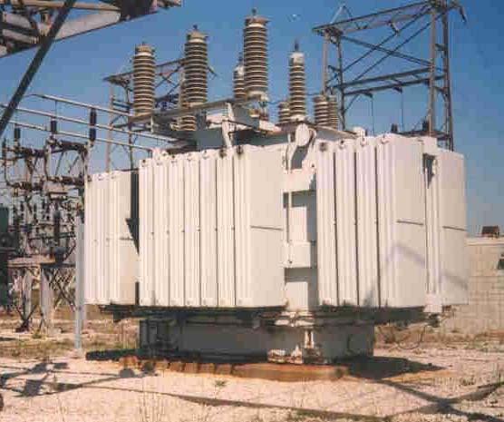
4 Transformers: T & D 4
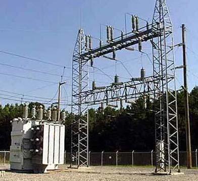
5 Transformers: T & D 5

6 Transformer: GSU Step Up 6
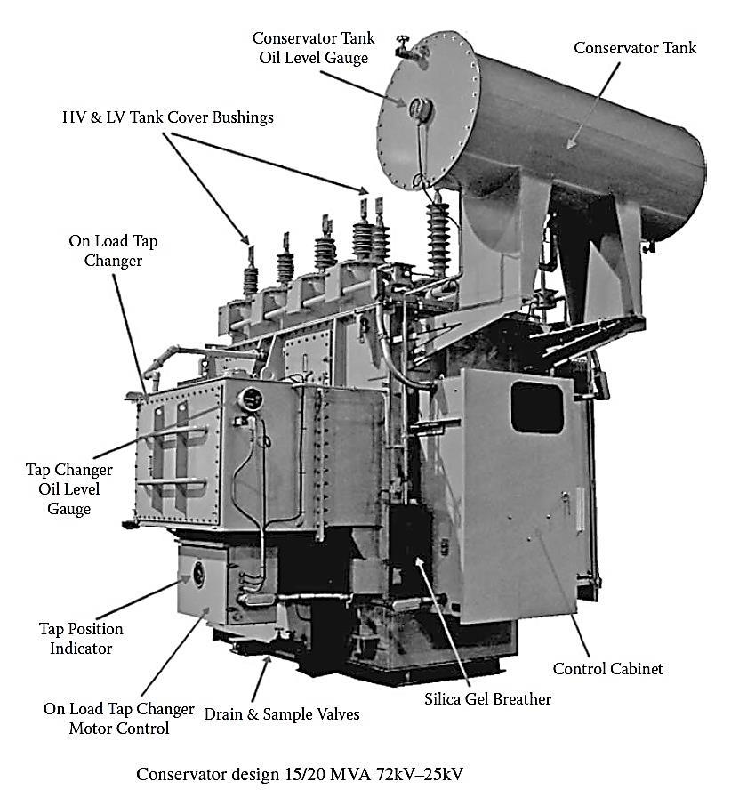
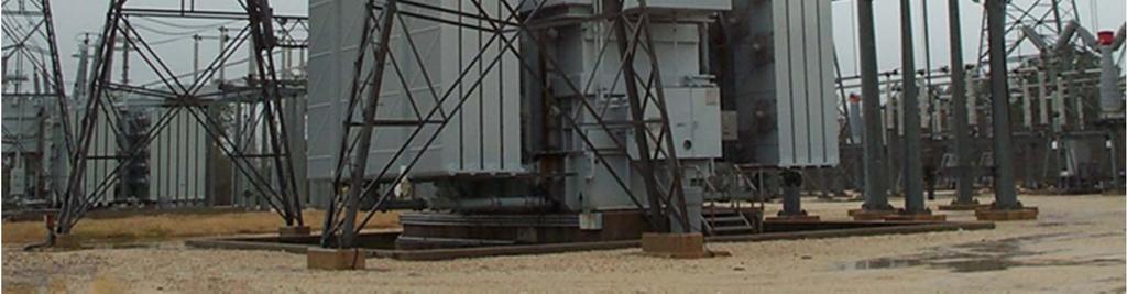
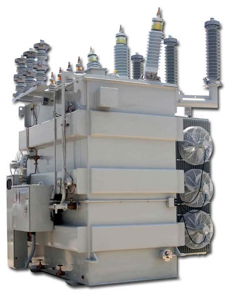
7 Key Components 7

8 FAILURE! 8

9 FAILURE! 9

10 FAILURE! 10
11 Why Do Transformers Fail? The electrical windings and the magnetic core in a transformer are subject to a number of different forces during operation: Expansion and contraction due to thermal cycling Vibration Local heating due to magnetic flux Impact forces due to through-fault current Excessive heating due to overloading or inadequate cooling 11

12 Costs and Other Factors To Be Considered Cost of repairing damage Cost of lost production Adverse effects on the balance of the system The spread of damage to adjacent equipment The period of unavailability of the damaged equipment 12


13 What Fails in Transformers? Windings - Insulation deterioration from: Moisture Overheating Vibration Voltage surges Mechanical Stress from through-faults LTCs - Malfunction of mechanical switching mechanism - High resistance contacts - Overheating - Contamination of insulating oil 13
14 What Fails in Transformers? Bushings - General aging - Contamination - Cracking - Internal moisture Core Problems - Core insulation failure - Open ground strap - Shorted laminations - Core overheating 14


15 Core Construction Shell construction is lighter than core construction 3-leg shell core causes zero sequence coupling 15

16 What Fails in Transformers? Miscellaneous - CT Issues - Oil leakage - Oil contamination Metal particles Moisture 16
17 Failure Statistics of Transformers Failure Statistics of Transformers Number % of Total Number % of Total Number % of Total Winding failures Tap changer failures Bushing failures Terminal board failures Core failures Miscellaneous Total IEEE
18 Failure Statistics of Transformers: 110kV-149kV IEEE
19 Failure Statistics of Transformers: 150kV-199kV IEEE
20 Failure Statistics of Transformers: 200kV-299kV IEEE


21 Analysis of Transformer Failures* *Data taken from Analysis of Transformer Failures by William H Bartley, Presented at the International Association of Engineering Insurers 36th Annual Conference Stockholm,
22 ANSI / IEEE C Guide for Protective Relay Applications for Power Transformers 87 = Phase Diff 51G = Ground Overcurrent 50/51 = Phase Overcurrent 64G = Transformer Tank Ground Overcurrent 26 = Thermal Device 49 = Thermal Overload 24 = Overexcitation 63 = Gas Relay (SPR, Buccholtz) Class III and IV Transformers (>= 5MVA) From IEEE C37.91,
 64G: Transformer Tank")
23 IEEE Devices used in 24: Overexcitation (V/Hz) 26: Thermal Device 46: Negative Sequence Overcurrent 49: Thermal Overload 50: Instantaneous Phase Overcurrent 50G: Instantaneous Ground Overcurrent 50N: Instantaneous Residual Overcurrent 50BF: Breaker Failure 51G: Ground Inverse Time Overcurrent 51N: Residual Inverse Time Overcurrent 63: Sudden Pressure Relay (Buccholtz Relay) 64G: Transformer Tank Ground Overcurrent 81U: Underfrequency 87H: Unrestrained Phase Differential 87T: Transformer Phase Differential with Restraints 87GD: Ground Differential (also known as restricted earth fault ) 23
24 Review Internal Short Circuits - Phase Faults - Ground Faults System Short Circuits (Back Up Protection) - Buses and Lines Phase Faults Ground Faults Abnormal Conditions - Open Circuits - Overexcitation - Abnormal Frequency - Abnormal Voltage - Breaker Failure - Overload - Geo-magnetically induced current (GIC) 24


25 Occurs in near polar and polar latitudes Result of solar storms impacting earth and causing induction and current loops Currents are DC and cause saturation of power transformers Proactive protection consists of: Deliberate system compartmentalizing or transformer isolation Use of capacitors on transformer grounds to block DC path Special Subject: GIC 25
26 Types of Protection Mechanical Accumulated Gases - Arcing by-products (Buchholz Relay) Pressure Relays - Arcing causing pressure waves in oil or gas space (Sudden Pressure Relay) Thermal - Caused by overload, overexcitation, harmonics and Geo-magnetically induced currents (GIC) Hot spot temperature Top Oil LTC Overheating 26

27 Sealing Transformers from Air/Moisture Intrusion Electric Power Engineering Handbook 27 27


28 Gas accumulator relay Applicable to conservator tanks equipped Operates for small faults by accumulating the gas over a period of time Typically used for alarming only Operates or for large faults that force the oil through the relay at a high velocity Used to trip Able to detect a small volume of gas and accordingly can detect arcs of low energy Detects High-resistance joints High eddy currents between laminations Low- and high-energy arcing Accelerated aging caused by overloading Buchholz Relay 28
29 When high current passes through a shorted turn, a great deal of heat is generated Detect large and small faults This heat, along with the accompanying arcing, breaks down the oil into combustible gases Gas generation increases pressure within the tank A sudden increase in gas pressure can be detected by a sudden-pressure relay located either in the gas space or under the oil The sudden-pressure can operate before relays sensing electrical quantities, thus limiting damage to the transformer Sudden Pressure Relay 29
30 Drawback of using sudden-pressure relays is tendency to operate on highcurrent through-faults The sudden high current experienced from a close-in through-fault causes windings of the transformer to move. This movement causes a pressure wave that is transmitted through the oil Countermeasures: Overcurrent relay supervision Any high-current condition detected by the instantaneous overcurrent relay blocks the sudden-pressure relay Sudden Pressure Relay This method limits the sudden-pressure relay to low-current incipient fault detection. Place sudden-pressure relays on opposite corners of the transformer tank. Any pressure wave due to through-faults will not be detected by both sudden-pressure relays. The contacts of the sudden-pressure relay are connected in series so both must operate before tripping. 30
31 Sudden Pressure Relay Supervision Scheme Phase and Ground Overcurrent supervises SPR (63) SPR (63) employs Pickup delay for overcurrent supervision Drop out delay to allow SPR (63) to reset 31 31
32 Causes of Transformer Overheating Transformers may overheat due to the following reasons: High ambient temperatures Failure of cooling system External fault not cleared promptly Overload Abnormal system conditions such as low frequency, high voltage, nonsinusoidal load current, or phase-voltage unbalance 32

33 Transformer Overheating Undesirable results of overheating Overheating shortens the life of the transformer insulation in proportion to the duration of the high temperature and in proportion to the degree of the high temperature. Severe over temperature may result in an immediate insulation failure (fault) Overheating can generate gases that could result in an electrical failure (fault) Severe over temperature may result in the transformer coolant heated above its flash temperature, with a resultant fire (fault and a bang!). 33


34 Heating and Relative Transformer Temperatures Temperature may be monitored multiple places Hot Spot Top Oil Bottom Oil LTC Tank Delta of the above The hot spot is, as then name indicates, the hottest spot Other temperatures are lower Standard Handbook for Electrical Engineers 34 34
35 Transformer Temperature Monitoring T A Transformer Sensing Inputs (Typical) I Fans T CI LOL Main T TO T HS T TO TP LOL LTC I Motor T LTC LEGEND: T = Temperature TO = Top Oil Wind = Winding LOL = Low Oil Level I = Current CO = Cooler Outlet CI = Cooler Inlet A = Ambient LTC = Load tapchanger TP = Tap Position T CO Electrical Quantities 3 Phase Currents 1 Neutral Current 3 Phase Voltages 35


36 Fiberoptic sensors Use Gallium Arsenic (GaAs) based spectrophotometric module Measures the spectrum a temperature-dependent GaAs crystal affixed on optical fiber Typical on newly constructed transformers Difficult to retrofit More exact that IEEE calculation approximations Aging Factor = multiples of 1 hour of normal temperature use Hot Spot Detection Transformer Winding Hot Spot Temperature Determination, 2006, Qualitrol 36
37 Transformer Electrical Protection Issues Breaker Failure Breaker Failure Overload Phase Fault Phase Fault Ground Overexcitation Fault Underfrequency Undervoltage Open Conductor Ground Fault In and Out of Zone 37
38 Complex Applications 38
39 Complex Applications 39
40 M-3311A Typical Connection Diagram Two Winding Model CT 2 Winding This function is available as a standard protective function. This function is available in the Optional Voltage Protection Package A M-3311A Targets (Optional) TF CT Winding 1 (W1) Integral HMI (Optional) Metering 87T 87H 51N Sequence Of Events Waveform Capture 87 GD 51N 50G 51G CT Winding 2 (W2) IRIG-B Front RS232 Communication 50N BF 59G R Rear RS-232/485 Communication Multiple Setting Groups VT Programmable I/O Programmable Logic Self Diagnostics 24 81U B 50 BF CT 40
41 3 Winding A TF 41
42 M-3311A Typical Connection Diagram Four Winding Model This function is available as a standard protective function. This function is available in the Optional Voltage Protection Packages. Winding 4 (W4) 3 CT Winding 1 (W1) 3 CT 4 Winding M-3311A Targets (Optional) 1 50BF * Integral HMI (Optional) 51N 50N A Metering Sequence Of Events Waveform Capture 1 50BF * V G 2 2 V 0 VT 1 VT 59G O/U 59 IRIG-B Front RS232 Communication Rear RS-232/485 Communication 87GD 51N 50N 1 50G 51G Winding 2 (W2) 1 CT Winding 3 (W3) Multiple Setting Groups Programmable I/O 50N 87GD 1 50G 51G 1 CT Programmable Logic 51N 50N R R Self Diagnostics Dual Power Supply (Optional) 50N BF 51N RJ45 Ethernet (Optional) 50N BF 87H 87T 1 50BF * B C 1 50BF * 3 CT 3 CT 42

43 4 Winding w/current Summing 43

44 Desirable Sensing Possibilities Many ground Inputs available for 87GD (REF), 51G Many voltage inputs available for 24, 59, 59N, 27, 81-0, 81-U Current Summing available on two sets of current inputs o Useful for thru-fault on dual high side CB applications 44
45 Types of Protection Electrical Fuses - Small transformers (typ. <10 MVA) - Short circuit protection only Overcurrent protection - High side Through fault protection Differential back-up protection for high side faults - Low side System back up protection Unbalanced load protection 45
46 Functions Internal Faults: 87T Phase Differential with Restraints 87H Unrestrained Phase Differential 87GD Three Ground Differential elements (Restricted Earth Fault) 64G Tank Ground Overcurrent Through Faults: 50/51 Phase Overcurrent 50G/51G Ground Overcurrent 50N/51N Instantaneous Residual Overcurrent 46 Negative Sequence Overcurrent 46
47 Functions Abnormal Operating Conditions: 27 Undervoltage 24 Overexcitation (V/Hz) 49 Thermal Overload 81U Underfrequency 50BF Breaker Failure Asset Management Functions: TF Through Fault Monitoring BM Breaker Monitoring TCM Trip Circuit Monitoring 47
48 High Side Overcurrent Back up to differential, sudden pressure Coordinated with line protection off the bus Do not want to trip for low-side external faults 48
49 High Side Overcurrent for Internal Fault Set to pick up at a value higher than the maximum asymmetrical through-fault current. This is usually the fault current through the transformer for a lowside three-phase short circuit. Instantaneous units that are subject to transient overreach are set for pickup in the range of 125% to

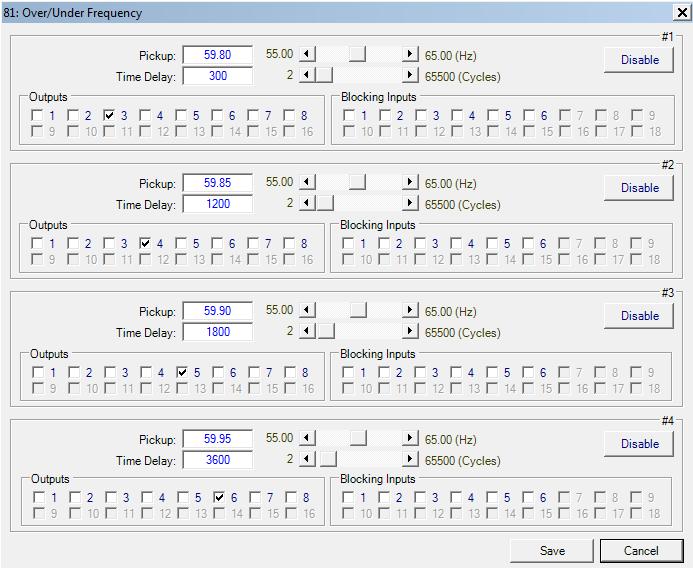
50 51 Function Settings 50

51 50 Function Settings 51
52 Low Side Overcurrent Provides protection against uncleared faults downstream of the transformer May consist of phase and ground elements Coordinated with downline protection off the bus 52
53 Negative Sequence Overcurrent 46 Negative sequence overcurrent provides protection against Unbalanced loads Open conductors Phase-to-phase faults Ground faults Does not protect against 3-phase faults 53
54 Negative Sequence Overcurrent Can be connected in the primary supply to protect for secondary phase-to-ground or phase-to-phase faults Helpful on delta-wye grounded transformers where only 58% of the secondary p.u. phase-to-ground fault current appears in any one primary phase conductor 46 54
55 Negative Sequence Overcurrent 46 Provides better protection than phase overcurrent relays for internal transformer faults The relay must also be set higher than the negative-sequence current due to unbalanced loads The relay should be set to coordinate with the low-side phase and ground relays for phase-to-ground and phase-to-phase faults 55
56 Negative Sequence Overcurrent Negative sequence relays can be set below load current levels and be more sensitively than phase overcurrent relays for phase-to-phase fault detection 46 In many applications, phase overcurrent relay pickup settings can be higher allowing more feeder load capability. 56

57 46 Function Settings 57
58 Through Fault Provides protection against cumulative through fault damage Typically alarm function 58


59 WSU Hands-On Relay School 2018 A transformer is like a motor that does not spin There are still forces acting in it That is why we care about limiting through-faults Through Fault Electric Power Engineering Handbook 59 59
60 Through Fault Monitoring Protection against heavy prolonged through faults Transformer Category -IEEE Std. C Curves Minimum nameplate (kva) Category Single-Phase Three-Phase I II III , ,000 IV Above 10,000 Above 30,000 60

61 Through Fault Damage Mechanisms Thermal Limits for prolonged through faults typically 1-5X rated Time limit of many seconds Mechanical Limits for shorter duration through faults typically greater than 5X rated Time limit of few seconds NOTE: Occurrence limits on each Transformer Class Graph Standard Handbook for Electrical Engineers 61 61


62 Through Fault Category 1 (15 kva 500 kva) From IEEE C

 From IEEE C37.")
63 Through Fault Category 2 (501 kva 5 MVA) Through Fault damage increases for a given amount of transformer Z%, as more I (I 2 ) through the Z results in higher energy (forces) From IEEE C
64 Cat. 2 & 3 Fault Frequency Zones (501 kva - 30 MVA) From IEEE C

 through the Z results in higher energy")
65 Through Fault Category MVA 30 MVA Through Fault damage increases for a given amount of transformer Z%, as more I (I 2 ) through the Z results in higher energy (forces) From IEEE C


66 Through Fault Category 4 (>30 MVA) Through Fault damage increases for a given amount of transformer Z%, as more I (I 2 ) through the Z results in higher energy (forces) 66
67 Targets (Optional) Integral HMI (Optional) Metering Sequence Of Events Waveform Capture 50BF Sum TF 51 Sum 49 Sum Winding 4 (W4) 3 CT 59G A Winding 1 (W1) 3 CT VT 1 VT V G O/U 4 Winding w/current Summing & Through Fault IRIG-B Front RS232 Communication Rear RS-232/485 Communication 51N Sum 87GD 50N 50G 51G Winding 2 (W2) 1 CT Winding 3 (W3) Multiple Setting Groups Programmable I/O 50N 87GD 50G 51G 1 CT Programmable Logic 51N 50N R R Self Diagnostics Dual Power Supply (Optional) 50N BF 51N RJ45 Ethernet (Optional) 50N BF B C 87H 87T 50BF CT 50BF CT 67
68 Through Fault Function Settings (TF) Should have a current threshold to discriminate between mechanical and thermal damage areas May ignore through faults in the thermal damage zone that fails to meet recording criteria Should have a minimum through fault event time delay to ignore short transient through faults Should have a through fault operations counter Any through fault that meets recording criteria increments counter Should have a preset for application on existing assets with through fault history Should have cumulative I 2 t setting How total damage is tracked Should use inrush restraint to not record inrush periods Inrush does not place the mechanical forces to the transformer as does a through fault 68

69 Through Fault Function Settings (TF) 69

70 Overexcitation Responds to overfluxing; excessive V/Hz 120V/60Hz = 2 = 1pu Constant operational limits o ANSI C & C loaded, 1.10 unloaded o Inverse time curves typically available for values over the constant allowable level Overfluxing is a voltage and frequency based issue Overfluxing protection needs to be voltage and frequency based (V/Hz) Although 5 th harmonic is generated during an overfluxing event, there is no correlation between levels of 5 th harmonic and severity of overfluxing Apparatus (transformers and generators) is rated with V/Hz withstand curves and limits not 5 th harmonic withstand limits 70
71 Overexcitation vs. Overvoltage Overvoltage protection reacts to dielectric limits. Exceed those limits and risk punching a hole in the insulation Time is not negotiable Overexcitation protection reacts to overfluxing Overfluxing causes heating The voltage excursion may be less than the prohibited dielectric limits (overvoltage limit) Time is not negotiable The excess current cause excess heating which will cumulatively damage the asset, and if left long enough, will cause a catastrophic failure 71 71

72 Causes of Overexcitation Generating Plants o Excitation system runaway o Sudden loss of load o Operational issues (reduced frequency) Static starts Pumped hydro starting Rotor warming Transmission Systems o Voltage and Reactive Support Control Failures Capacitor banks ON when they should be OFF Shunt reactors OFF when they should be ON Near-end breaker failures resulting in voltage rise on line Ferranti Effect Runaway LTCs Load Loss on Long Lines (Capacitive Charging Voltage Rise) 72
73 System Control Issues: Overvoltage and Overexcitation 73
74 System Control Issues: Overvoltage and Overexcitation 74
75 System Control Issues: Overvoltage and Overexcitation MVAR Ferranti Effect MVAR MVAR 75
76 System Control Issues: Overvoltage and Overexcitation Run-Away LTC MVAR MVAR MVAR 76
77 System Control Issues: Overvoltage and Overexcitation Generation Load MVAR 1996 WECC Load Rejection Event 77
78 Overexcitation Event 78
79 Overexcitation Curves This is typically how the apparatus manufacturer specifies the V/Hz curves 79
80 Overexcitation Curves This is typically how the apparatus manufacturer specifies the V/Hz curves 80
81 Overexcitation Relay Curves This is how protection engineers enter the v/hz curve into a protective device 81
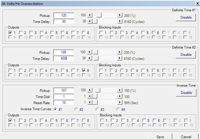
82 Overexcitation (24) 82
83 Types of Protection: Differential Advantages Provides high speed detection of faults that can reduce damage due to the flow of fault currents Offers high speed isolation of the faulted transformer, preserving stability and decreasing momentary sag duration No need to coordinate with other protections The location of the fault is determined more precisely Within the zone of differential protection as demarked by CT location 83
84 Types of Protection: Phase Differential - Applied with variable percentage slopes to accommodate CT saturation and CT ratio errors - Applied with inrush and overexcitation restraints - Pickup/slope setting should consider: magnetizing current, turns ratio errors due to fixed taps and +/- 10% variation due to LTC - May not be sensitive enough for all faults (low level, ground faults near neutral) 84
85 Phase Differential: Basic Differential Relay TRANSFORMER RELAY Operate TAP W-1 Restraint W-1 Restraint W-2 TAP W-2 85
86 Basic Differential Relay - External Fault TRANSFORMER RELAY Operate = 0 TAP W-1 Restraint W-1 Restraint W-2 TAP W-2 86
87 Basic Differential Relay - Internal Fault TRANSFORMER RELAY Operate TAP W-1 Restraint W-1 Restraint W-2 TAP W-2 87
88 Differential Protection What goes into a unit comes out of a unit Kirchoff s Law: The sum of the currents entering and leaving a junction is zero Straight forward concept, but not that simple in practice with transformers A host of issues challenges security and reliability of transformer differential protection 88
89 Typical Phase Differential Characteristic I 1 + I 2 + I 3 = 0 I 1 I UNIT 2 I 3 89
90 Unique Issues Applying to Transformer Differential Protection CT ratio caused current mismatch Transformation ratio caused current mismatch (fixed taps) LTC induced current mismatch Delta-wye transformation of currents - Vector group and current derivation issues Zero-sequence current elimination for external ground faults on wye windings Inrush phenomena and its resultant current mismatch 90
91 Harmonic content available during inrush period due to point-on-wave switching Especially with newer transformers with step-lap core construction Overexcitation phenomena and its resultant current mismatch Internal ground fault sensitivity concerns Switch onto fault concerns Unique Issues Applying to Transformer Differential Protection CT saturation, remanance and tolerance 91
92 Application Considerations: Paralleling Sources When paralleling sources for differential protection, beware! Paralleled sources (not load, specifically sources) have different saturation characteristics and present the differential element input with corrupt values Consider through-fault on bus section One CT saturates, the other does not Result: Input is presented with false difference due to combining of CTs from different sources outside of relay 92
93 Differential Element Security Challenge The problem with external faults is the possibility of CT saturation making an external fault look internal to the differential relay element 93 From IEEE C

94 CT Performance: 200:5, C200, R=0.5, Offset = 0.5, 1000A 94

95 CT Performance: 200:5, C200, R=0.5, Offset = 0.5, 2000A 95

96 CT Performance: 200:5, C200, R=0.5, Offset = 0.75, 2000A 96

97 CT Performance: 200:5, C200, R=0.75, Offset = 0.75, 2000A 97

98 CT Performance: 400:5, C400, R=0.5, Offset = 0.5, 2000A 98

99 CT Performance: 400:5, C400, R=0.5, Offset = 0.5, 4000A 99

100 CT Performance: 400:5, C400, R=0.5, Offset = 0.5, 8000A 100

101 CT Performance: 400:5, C400, R=0.5, Offset = 0.75, 8000A 101

102 CT Performance: 400:5, C400, R=0.75, Offset = 0.75, 8000A 102
103 Through Current: Perfect Replication 4 pu 2 Node Bus 10 I D = I 1 + I (0,0) (4, 4) 6 TRIP RESTRAIN A B I R = I 1 + I 2 A B 103
104 Through Current: Imperfect Replication 4 pu 2 Node Bus I D = I 1 + I 2 +4 B (2, -2) (1, -3) C 6 4 TRIP 0 2 C RESTRAIN 4 A B A (0,0) I R = I 1 + I 2 104
105 Internal Fault: Perfect Replication 2 pu 2 pu 10 I D = I 1 + I 2 2 Node Bus (0, 0) (2, 2) 6 TRIP B RESTRAIN 2 A I R = I 1 + I 2 A B 105
106 Internal Fault: Imperfect Replication 2 pu 2 pu 10 I D = I 1 + I Node Bus 87 (0, 0) (2, 0.5) 8 6 TRIP B RESTRAIN 2 A B A I R = I 1 + I 2 106
107 Application Considerations: Paralleling Sources When paralleling sources for differential protection, beware! Paralleled sources (not load, specifically sources) have different saturation characteristics and present the differential element input with corrupt values Consider through-fault on bus section One CT saturates, the other does not Result: Input is presented with false difference due to combining of CTs from different sources outside of relay 107
108 Classical Differential Compensation CT ratios must be selected to account for: - Transformer ratios - If delta or wye connected CTs are applied - Delta increases ratio by 1.73 Delta CTs must be used to filter zero-sequence current on wye transformer windings 108
109 Classical Differential Compensation Dab as polarity of A connected to non-polarity of B 109
110 Bushing Nomenclature H1, H2, H3 Primary Bushings X1, X2, X3 Secondary Bushings H1 H2 H3 Transformer X1 X2 X3 Wye-Wye Delta-Delta Delta-Wye Wye-Delta H1 and X1 at zero degrees H1 and X1 at zero degrees H1 lead X1 by 30 degrees H1 lead X1 by 30 degrees ANSI Standard 110
111 Angular Displacement ANSI Y-Y & 0 ANSI Y- & H1 lead X1 by 30 or X1 lag H1 by
112 Winding Types and Impacts Wye-Wye Cheaper than 2 winding if autobank Conduct zero-sequence between circuits Provides ground source for secondary circuit Delta-Delta Blocks zero-sequence between circuits Does not provide a ground source Delta-Wye Blocks zero-sequence between circuits Provides ground source for secondary circuit Wye-Delta Blocks zero-sequence between circuits Does not provide a ground source for secondary circuit 112

113 Wye-Wye Winding Types Industrial Power Distribution

114 Delta-Delta Winding Types Industrial Power Distribution

115 Delta-Wye Winding Types Industrial Power Distribution


116 Wye-Delta Winding Types Industrial Power Distribution
117 Compensation in Digital Relays Transformer ratio CT ratio Phase angle shift and 3 factor due to delta/wye connection Zero-sequence current filtering for wye windings so the differential quantities do not occur from external ground faults 117
118 Phase Angle Compensation in Numerical Relays Phase angle shift due to transformer connection in electromechanical and static relays is accomplished using appropriate connection of the CTs The phase angle shift in Numerical Relays can be compensated in software for any transformer with zero or 30 increments All CTs may be connected in WYE which allows the same CTs to be used for both metering and backup overcurrent functions Some numerical relays will allow for delta CTs to accommodate legacy upgrade applications 118
119 Delta High Side, Wye Low Side High Lead Low by 30 Delta-Wye Delta (ab) Dy1 Dyn1 Wye High Side, Delta Low Side High Lead Low by 30 Wye-Delta Delta (ac) Yd1 YNd1 119
120 Delta High Side, Wye Low Side High Lead Low by 30 Delta-Wye Delta (ab) Dy1 Dyn1 Wye High Side, Delta Low Side High Lead Low by 30 Wye-Delta Delta (ac) Yd1 YNd1 120

121 Y-Y ANSI - ANSI Y- ANSI Transformer Connection Bushing Nomenclature -Y ANSI ANSI follows zero phase shift, or high lead low by 30 IEC designations use low lags high by increments of 30 phase shift IEC uses various phase shifts in 30 increments 30, 60, 90, 180, etc. 121
122 Digital Relay Application M-3311A All WYE CTs shown 122
123 Benefits of Wye CTs Phase segregated line currents - Individual line current oscillography - Currents may be easily used for overcurrent protection and metering - Easier to commission and troubleshoot - Zero sequence elimination performed by calculation NOTE: For protection upgrade applications where one wants to keep the existing wiring, the relay must: Accept either delta or wye CTs For delta CTs, recalculate the phase currents for overcurrent functions 123
124 Application Adaptation Challenge: To be able to handle ANY combination of transformer winding arrangements and CT connection arrangements Strategy: Use a menu that contains EVERY possible combination - Set W1 s transformer winding configuration and CT configuration - Set W2 s transformer winding configuration and CT configuration - Set W3 s transformer winding configuration and CT configuration - Set W4 s transformer winding configuration and CT configuration - Standard or Custom Selection Standard handles most arrangements, including all ANSI standard type Custom allows any possible connections to be accommodated (Non-ANSI and legacy delta CTs) - Relay selects the proper currents to use, directly or through vector subtraction - Relay applies 3 factor if required - Relay applies zero sequence filtering if required 124
125 Compensation: Base Model 125
126 Compensation: Change in CT Ratio 126
127 Compensation: Transformer Ratio 127
128 Compensation: Delta Wye Transformation IA, IB, IC 1:1, 3Y IA', IB', IC' 1:1, 3Y Ia', Ib', Ic' Ia, Ib, Ic ANSI standard, high lead low by 30, Current pairs are: IA IB, IB IC, IC IA 128
129 Compensation: Zero-Sequence Elimination 3I 0 = [I a + I b + I c ] I 0 = 1/3 *[I a + I b + I c ] Used where filtering is required (Ex: Y/Y transformer). 129


130 Standard Application Set winding types 6 choices of configuration for windings and CTs CT Winding 130

131 Custom Application: Accommodates any CTs and Windings Winding 131
 x1/ 3 ( )")
132 Custom Application: Accommodates any CTs and Windings CT x1 (Y) x1/ 3 ( ) 132
133 Core Construction and 3I 0 Current Unit transformer with Three-Legged Core With a 3 legged core, the zero-sequence current contribution of the transformer case may contribute as much as 20% to 25% zero-sequence current. o This is true regardless of if there is delta winding involved o Use 3I 0 restraint on wye CTs even on the delta CT winding!!! o Use 3I 0 restraint on wye CTs with wye windings!!! 133
134 Custom Application: Accommodates any CTs Legacy Application Need to keep Delta CTs on WYE side of transformer 134
135 Custom Application: Accommodates any CTs A High Side Low Side A B B C C M 3311A IA-IB A A IA -IB IB-IC B B IB -IC Legacy Application IC-IA C C IC -IA Need to keep Delta CTs on WYE side of transformer 135
136 Relay Custom Application I0 =0 Delta I0 I0 Ground Fault M

137 Zig-Zag Winding Types Provides Ground Source for Ungrounded systems Industrial Power Distribution 137


138 Wye-Delta Ground Bank Winding Types Provides Ground Source for Ungrounded Systems Industrial Power Distribution 138
139 Inrush Detection and Restraint Characterized by current into one winding of transformer, and not out of the other winding(s) This causes a differential element to pickup Use inrush restraint to block differential element during inrush period Initial inrush occurs during transformer energizing as the core magnetizes Sympathy inrush occurs from adjacent transformer(s) energizing, fault removal, allowing the transformer to undergo a low level inrush Recovery Inrush occurs after an out-of-zone fault is cleared and the fault induced depressed voltage suddenly rises to rated. 139
140 Classical Inrush Detection 2 nd harmonic restraint has been employed for years Gap detection has also been employed As transformers are designed to closer tolerances, the incidence of both 2 nd harmonic and low current gaps in waveform have decreased If 2 nd harmonic restraint level is set too low, differential element may be blocked for internal faults with CT saturation (with associated harmonics generated) 140
141 Advanced Inrush Detection 4 th harmonic is also generated during inrush Even harmonics are more prevalent than odd harmonics during inrush Odd harmonics are more prevalent during CT saturation Use 4 th harmonic and 2 nd harmonic together Use RMS sum of the 2 nd and 4 th harmonic as inrush restraint Result: Improved security while not sacrificing reliability 141

142 Inrush Oscillograph 2nd and 4th Harmonics During Inrush Typical Transformer Inrush Waveform 142

143 Inrush Oscillograph Typical Transformer Inrush Waveform 143
144 Point-on-Wave Considerations During Switch On As most circuit breakers are ganged three-pole, one phase will be near voltage zero at the moment of transformer energization When a phase of a transformer is switched on near zero voltage, the inrush is increased and so is the resultant harmonics Low levels of harmonics (especially modern transformers) may not provide inrush restraint for affected phase security risk! Employ cross-phase averaging to compensate for this issue 144
145 Cross Phase Averaging Provides security if a phase(s) has low harmonic content during inrush Cross phase averaging uses the sum of harmonics on all three phases as the restraint value Cross Phase Averaging (harmonic sharing) is a modification of the harmonic blocking technique The harmonic content of all three phases is summed before checking the ratio of the fundamental to harmonic This approach adds security in applications in which harmonic content on one or two phases is not sufficient to block the operation of the relay 145
146 Overexcitation Restraint Overexcitation occurs when volts per hertz level rises (V/Hz) above the rated value This may occur from: - Load rejection (generator transformers) - Malfunctioning of voltage and reactive support elements - Malfunctioning of breakers and line protection (including transfer trip communication equipment schemes) - Malfunctioning of generator AVRs The voltage rise at nominal frequency causes the V/Hz to rise This causes the transformer core to saturate and thereby increase the magnetizing current. The increased magnetizing current contains 5 th harmonic component This magnetizing current causes the differential element to pickup Current into transformer that does not come out 146


147 Overexcitation Event 147
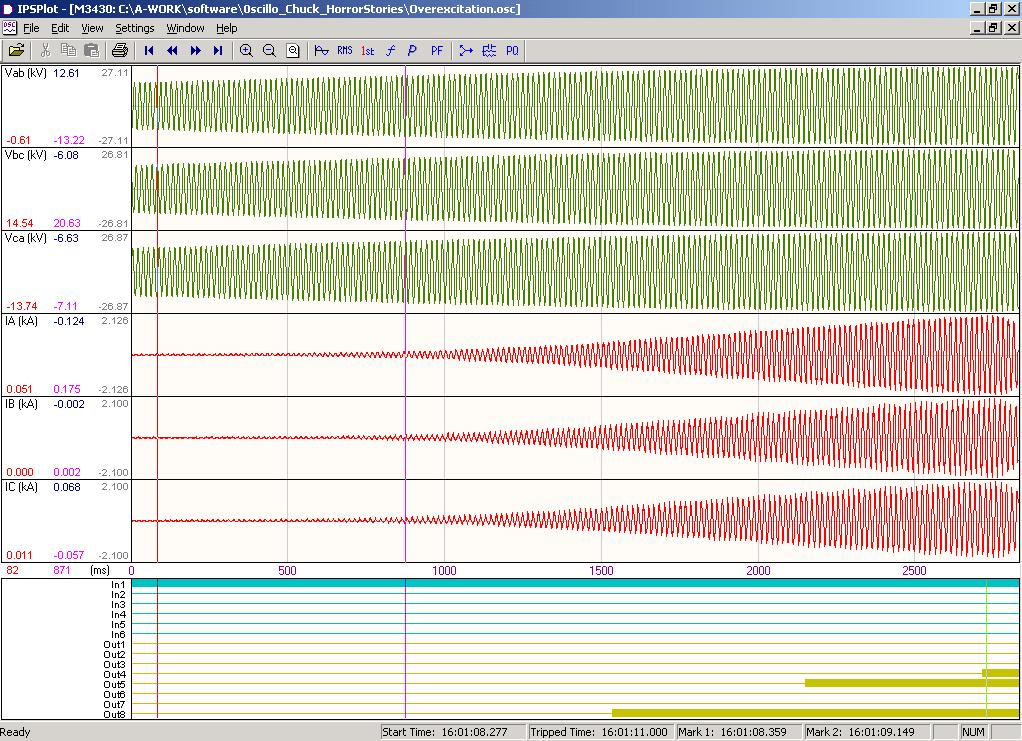
 Current 1.42kA (RMS)!!! 0.")
148 Overexcitation Event Voltage 19.40kV (RMS 11.57kV (RMS) Current 1.42kA (RMS)!!! 0.0 ka (RMS) 24 Elements Tripping 148

149 Overexcitation Event High 5th Harmonic Currents 149

150 Overexcitation Event 259V of 5th Harmonic 190 A of 5th Harmonic!!! 150
151 Overexcitation Restraint Use 5 th harmonic level to detect overexcitation Most relays block the differential element from functioning during transformer overexcitation If the transformer internally faults (1 or 2 Phase), the unfaulted phases(s) remain overexcited blocking the differential element Faulting during overexcitation is more likely if the voltage is greater than rated, as it will cause increased dielectric stress An improved strategy is to raise the pick up level of the differential element to accommodate the increased difference currents caused by the transformer saturation This allows the differential element to rapidly trip if an internal fault occurs during the overexcitation period Result: Improved reliability while not sacrificing security 151


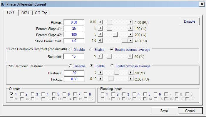
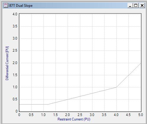
152 Trip Characteristic 87T TRIP Slope 2 87T Pick Up with 5th Harmonic Restraint T Pick Up Slope 1 RESTRAIN Slope 2 Breakpoint
153 Switch-onto-Fault Transformer is faulted on energizing Harmonic restraint on unfaulted phases may work against trip decision if cross phase averaging is used This may delay tripping until the inrush current is reduced 87H and 87GD can be used to provide high speed protection for this condition If fault is close to bushings current may be greater than 6-8pu High set element 87H can provide high speed protection for severe faults as this function is not restrained by harmonics 87H is set above the worst case inrush current 87GD function can provide fast protection during switching onto ground faults as this element is not restrained using harmonics 153
154 Phase Differential 87T element is typically set with 30-40% pickup This is to accommodate: Class C CT accuracy (+/- 10%, x20 nominal current) Effects of LTCs (+/- 10%) 87HS set to 9-12x rated current Inrush does not exceed 6-8x rated current That leaves a portion of the winding not covered for a ground fault (near the neutral) Employ a ground differential element to improve sensitivity (87GD) 154
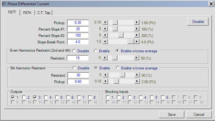


155 Phase Differential (87) 155

156 Phase Differential (87) 156
157 Phase Differential (87) Setting tap is a method used to nominalize the winding currents with respect to MVA, kv and CT ratio 157

158 Phase Differential (87) 158
159 Types of Protection: Ground Differential (87GD; REF) Sensitive detection of ground faults, including those near the neutral Does not require inrush or overexcitation restraint Low impedance grounded systems use directional signal for added stability Low impedance grounded systems do not require dedicated CTs Same set of CTs can be used for phase differential, phase overcurrent, ground differential and ground overcurrent protection 159
160 Types of Protection: Ground Differential (87GD; REF) 25MVA 69kV:13.8kV 3Y 400:5 3Y 1200:5 400A 1 3ɸ 3ɸ 3I 0 87 I N 87 GD 3ɸ 160
161 Improved Ground Fault Sensitivity Use 87GD I A + I B + I C = 3I 0 If fault is internal, opposite polarity. If fault is external, same polarity 161
162 87GD with Internal Fault, Double Fed I G 3I O 0-3I o x I G cos (180) = 3I o I G
163 87GD with External Through Fault A B Residual current (3I 0 ) calculated from individual phase currents Paralleled CTs shown to illustrate principle C 90 G I G 3I 0 3I O I G -3I o x I G cos (180) = 3I o I G
164 Improved Ground Fault Sensitivity (87GD) Direction calculation used with currents over 140mA on both sets of CTs (3 I0 and I G ) Directional element used to improve security for heavy external phase to phase faults that cause saturation When current >140mA, element uses current setting and directional signal When current <= 140mA, element uses current setting only Saturation will not occur at such low current levels Directional signal not required for security Allows element to function for internal faults without phase output current (open low side breaker, transformer energized) 164
165 87GD with Internal Fault, Single Feed I A I B 90 I G 3 I0 I C 180 I G I o x I G cos (180) = 3I o I G I G > setting 165

166 87GD Function May be used with Current Summing 166
167 Ground Fault Protection for Delta-Wye Transformer NOTE 1 NOTE 4 4. System must supply zero sequence current for this scheme to work From IEEE C
168 49 Thermal Overcurrent The Transformer Overload function (49) provides protection against possible damage during overload conditions IEC standard (presently under revision), provides both cold and hot curves The function uses the thermal time constant of the transformer and the maximum allowable continuous overload current (I max )inimplementingtheinversetime characteristic 168
169 49 Thermal Overcurrent The operating time is defined according to the standard IEC : 169

170 49 Thermal Overcurrent 170
171 Phasor Displays A very useful commissioning tool for viewing selected vectors Differential Displays uncompensated currents - You can see the phase shift and relative magnitudes Displays compensated currents - If they are equal in magnitude, and W2 and W3 are 180 degrees out from W1, the field wiring and relay settings are in agreement All Currents and Voltages Displays all values 171


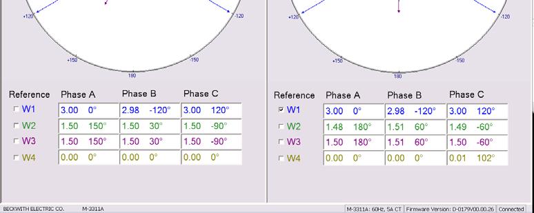
172 Phasor Diagram 172

173 Phasor Diagram 173
174 Phasor Display (Vectors) All Voltages and Currents Proper 174
175 Oscillography Uses Speed transformer s return to service if event is not an internal fault Identify type of testing needed In the transformer or system? Provide data to transformer manufacturer if asset health is in question Determine if relay and circuit breaker operated properly Identify relay, control or breaker problem Uncovers unexpected problems Settings Comtrade Oscillographs (*.cfg) 175
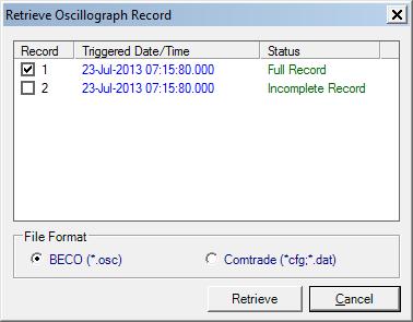
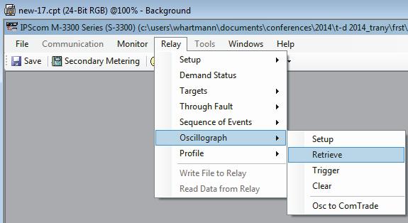
176 Retrieve Oscillographic Record 176


177 Opening an Oscillographic File (*.cfg or *.ocs) 177

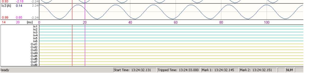
178 Waveform Capture 178

179 Test and Commissioning 179
180 Commissioning Tasks PAT Panel Acceptance Test Test from the panel terminal blocks to the relay SAT Includes test switches Site Acceptance Test Take successful PAT panel, and test with: Secondary injection from CT termination cabinet at transformer/switchyard Load pick up on transformer 180
181 Commissioning Tools Advanced Metering Sequence components for all windings Positive, negative and zero Restraint and differential currents Vector Metering Uncompensated Raw signal Compensated Post vector and ratio corrections Digital Oscillography All winding currents 181
182 Commissioning Examples Y-Y-Y, yyy, normal load flow Y-Y-Y, yyy, rolled A-phase on W2 -Y-Y, yyy, normal load flow -Y-Y, yyy, rolled A-phase on W1 -Y-Y, yyy, rolled C-phase on W1 182
183 Details Used test equipment to simulate 3 winding transformers of various winding and CT configurations Injected 3A into W1, injected 1.5A into W2 and W3 to simulate load flow Assumed 1:1 transformer and 1:1 CTs for easy viewing of principles Created correct base case Created incorrect case Used advanced protection system tools to diagnose the incorrect issue 183
184 Y:Y:Y, yyy, 1:1 Ratio, 1:1 CTs, Normal 184
185 Three Line: Y:Y:Y, 1:1 Ratio, 1:1 CTs, Normal 185

186 Advanced Metering: Y:Y:Y, 1:1 Ratio, 1:1 CTs, Normal Low levels of negative and zero sequence current High level of positive sequence current
187 Advanced Metering: Y:Y:Y, 1:1 Ratio, 1:1 CTs, Normal Very low differential current Very high restraint current 187

188 Vector Metering: Y:Y:Y, 1:1 Ratio, 1:1 CTs, Normal 188

189 Digital Oscillography: Y:Y:Y, 1:1 Ratio, 1:1 CTs, Normal W1, Phase A W2, Phase A W3, Phase A Analog Traces 189
190 Y:Y:Y, yyy, 1:1 Ratio, 1:1 CTs, Roll W2, ØA 190
191 Three Line: Y:Y:Y, 1:1 Ratio, 1:1 CTs, Roll ØA, W2 191
192 Advanced Metering: Y:Y:Y, 1:1 Ratio, 1:1 CTs, Roll ØA, W2 High level of positive sequence current Levels of negative and zero sequence current, Positive sequence current not at phase current level 192
193 Advanced Metering: Y:Y:Y, 1:1 Ratio, 1:1 CTs, Roll ØA, W2 High differential current Restraint current less than through current 193


194 Vector Metering: Y:Y:Y, 1:1 Ratio, 1:1 CTs, Roll ØA, W2 194

195 Digital Oscillography: Y:Y:Y, 1:1 Ratio, 1:1 CTs, Roll ØA, W2 W1, Phase A W2, Phase A W2, Phase A W3, Phase A Differential Trip Analog Traces 195
196 :Y:Y, yyy, 1:1 Ratio, 1:1 CTs, Normal 196
197 Three Line: :Y:Y, 1:1 Ratio, 1:1 CTs, Normal 197
198 Advanced Metering: :Y:Y, 1:1 Ratio, 1:1 CTs, Normal Low levels of negative and zero sequence current High level of positive sequence current

199 Advanced Metering: :Y:Y, 1:1 Ratio, 1:1 CTs, Normal Very low differential current Very high restraint current 199

200 Vector Metering: :Y:Y, 1:1 Ratio, 1:1 CTs, Normal 200

201 Digital Oscillography: :Y:Y, 1:1 Ratio, 1:1 CTs, Normal Analog Traces 201
202 :Y:Y, yyy, 1:1 Ratio, 1:1 CTs, Roll W1, ØA 202
203 Three Line: :Y:Y, 1:1 Ratio, 1:1 CTs, W1, Roll ØA 203
204 Advanced Metering: :Y:Y, 1:1 Ratio, 1:1 CTs, W1, Roll ØA Levels of negative and zero sequence current, Positive sequence current not at phase current level High level of positive sequence current 204
205 Advanced Metering: :Y:Y, 1:1 Ratio, 1:1 CTs, W1, Roll ØA High differential current Restraint current less than through current 205


206 Vector Metering: :Y:Y, 1:1 Ratio, 1:1 CTs, W1, Roll ØA 206
207 Digital Oscillography: :Y:Y, 1:1 Ratio, 1:1 CTs, W1, Roll ØA W1, Phase A W2, Phase A W3, Phase A Differential Trip Analog Traces
208 :Y:Y, yyy, 1:1 Ratio, 1:1 CTs, W1, Roll ØC 208
209 Three Line: :Y:Y, 1:1 Ratio, 1:1 CTs, W1, Roll ØC 209


210 Advanced Metering: :Y:Y, 1:1 Ratio, 1:1 CTs, W1, Roll ØC Hi I 2 & I 0 I ph =/= I 1 Hi I diff 210


211 Vector Metering: :Y:Y, 1:1 Ratio, 1:1 CTs, W1, Roll ØC Wdg1 -60 o Wdg1 0 o Wdg1 -60 o Wdgs 1, 2 & o 211


212 Digital Oscillography: :Y:Y, 1:1 Ratio, 1:1 CTs, W1, Roll ØC Wdg2&3 C-Ph Wdg1 C-Ph Analog Traces 212
213 Commissioning Tools Make Your Life Easier! Advanced Metering Sequence components for all windings Positive, negative and zero Restraint and differential currents Vector Metering Uncompensated Raw signal Compensated Post vector and ratio corrections Digital Oscillography All winding currents 213
214 M-3311A Typical Connection Diagram Two Winding Model CT 2 Winding This function is available as a standard protective function. This function is available in the Optional Voltage Protection Package A M-3311A Targets (Optional) CT Winding 1 (W1) Integral HMI (Optional) Metering 87T 87H 51N Sequence Of Events Waveform Capture 87 GD 51N 50G 51G CT Winding 2 (W2) IRIG-B Front RS232 Communication 50N BF 59G R Rear RS-232/485 Communication Multiple Setting Groups VT Programmable I/O Programmable Logic Self Diagnostics 24 81U B 50 BF CT 214
215 3 Winding 215
216 M-3311A Typical Connection Diagram Four Winding Model This function is available as a standard protective function. This function is available in the Optional Voltage Protection Packages. Winding 4 (W4) 3 CT Winding 1 (W1) 3 CT 4 Winding M-3311A Targets (Optional) 1 50BF * Integral HMI (Optional) 51N 50N A Metering Sequence Of Events Waveform Capture 1 50BF * V G 2 2 V 0 VT 1 VT 59G O/U 59 IRIG-B Front RS232 Communication Rear RS-232/485 Communication 87GD 51N 50N 1 50G 51G Winding 2 (W2) 1 CT Winding 3 (W3) Multiple Setting Groups Programmable I/O 50N 87GD 1 50G 51G 1 CT Programmable Logic 51N 50N R R Self Diagnostics Dual Power Supply (Optional) 50N BF 51N RJ45 Ethernet (Optional) 50N BF 87H 87T 1 50BF * B C 1 50BF * 3 CT 3 CT 216
217 M-3311A Typical Connection Diagram Four Winding Model M-3311A Targets (Optional) Integral HMI (Optional) Metering This function is available as a standard protective function. This function is available in the Optional Voltage Protection Package. Winding 4 (W4) 3 CT A Winding 1 (W1) 3 CT 4 Winding w/current Summing Sequence Of Events Waveform Capture 50BF Sum 50 Sum 1 51 Sum 49 Sum * 59G V G V o 2 2 VT 1 VT O/U 59 IRIG-B Front RS232 Communication Rear RS-232/485 Communication 51N Sum 87GD 50N 1 50G 51G Winding 2 (W2) 1 CT Winding 3 (W3) Multiple Setting Groups Programmable I/O 50N 87GD 1 50G 51G 1 CT Programmable Logic 51N 50N R R Self Diagnostics Dual Power Supply (Optional) 50N BF 51N RJ45 Ethernet (Optional) 50N BF 87H 87T 1 50BF * 3 CT B C 1 50BF * 3 CT * Two sets of summed winding cuurents can be enabled at a time. 217
218 Unique Features of Beckwith Relays Voltage inputs with overexcitation protection Adaptive overexcitation restraint based on 5th harmonic Use of 2 nd and 4 th harmonic for inrush restraint Up to three ground directional differential elements Current summing for 51 and 87GD functions to be used with breaker and a half configuration Through fault monitoring to schedule early maintenance and prevent transformer failures Graphical display of uncompensated and compensated phasors for each winding to help with test and commissioning Easy to access metering screens for test and commissioning User friendly setting of transformer/ct connection configurations 218
219 References 1. IEEE Guide for, ANSI/IEEE C IEEE Recommended Practice for Grounding of Industrial and Commercial Power Systems, IEEE Std Protective Relaying: Principles and Applications, 3 rd Ed.; Lew Blackburn and Thomas Domin, CRC Press 2007; ISBN# Protective Relaying for Power Generation Systems; Donald Reimert, CRC Press 2006; ISBN# Industrial Power Distribution; Dr. Ralph E. Fehr III, Wiley IEEE Press 2016; ISBN# Optimizing, Wayne Hartmann, presented at the Doble Conference

220 Beckwith Electric Protection Seminar Thank You Questions? 220

221 Interface and Analysis Software: Desirable Attributes NERC State of Reliability % of Relay Misoperations are due to human interface error Programming too complex Commissioning difficult Period Testing difficult 221
222 Interface and Analysis Software: Desirable Attributes PC Software package for setpoint interrogation and modification, metering, monitoring, and downloading oscillography records Oscillography Analysis Software package graphically displays to facilitate analysis, and print captured waveforms Be menu-driven, graphical, simple to use Autodocumentation to eliminates transcription errors 222
223 How do you set a relay? Set the configuration (relay environment) Set elements Define tripping and blocking assignments Review/print summary 223
224

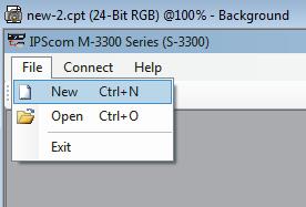
225 Creating NEW File


226 Opening EXISTING File


227 Connect to the Relay

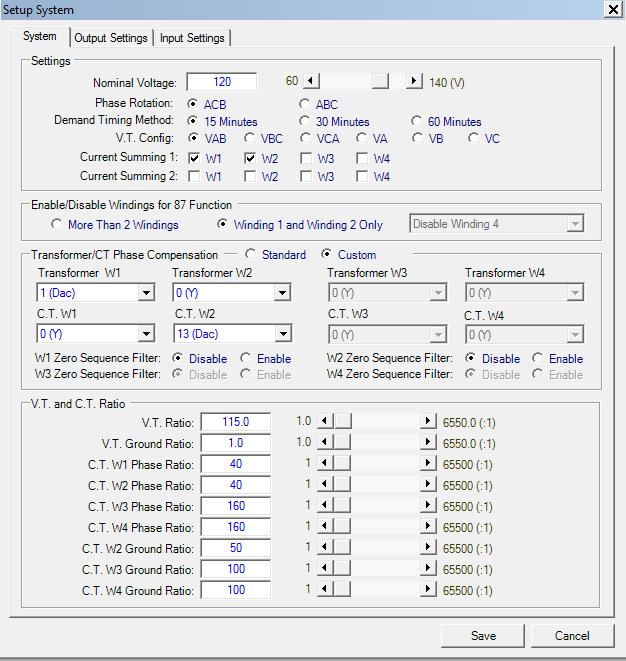
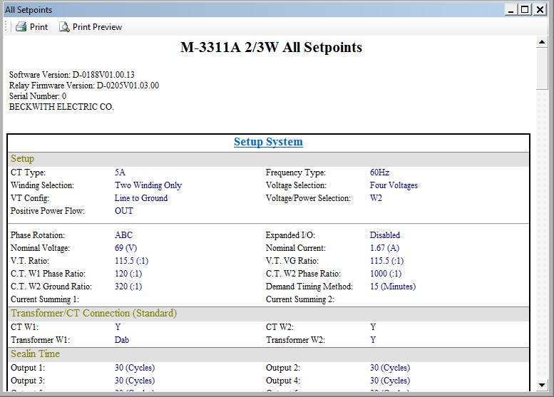
228 Set Up System

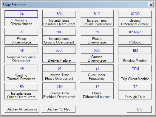
229 Relay Setpoints 229

230 Display I/O Map 230


231 Display I/O Map Element Disabled 231

232 Through Fault Recorder 232

233 Breaker Monitor 233

234 Setpoint Summary 234

235 Example: Programmable Logic 235

236 Example: Programmable Logic 236
237 Graphic Metering and Monitoring Metering of all measured inputs - Measured and calculated quantities Instrumentation grade Commissioning and Analysis Tools - Advanced metering - Event logs - Vector meters - R-X Graphics - Oscillograph recording 237


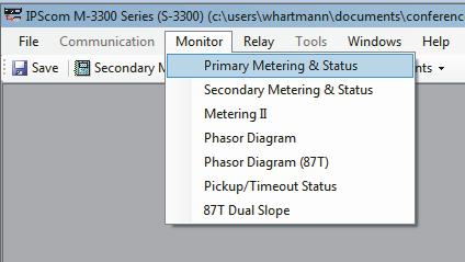
238 Primary Metering And Component Metering 238


239 Secondary Metering, Components Metering, and Status 239

240 Event Log Trigger Elements trigger on trip, drop out, pick up I/O triggers on pick up, drop out
")
241 Sequence of Events Recorder (total 512 Events are stored) 241
 51#1")

242 Function Status (Targets) 51#1 is picked up 87T has tripped 242

243 Differential Plot 243

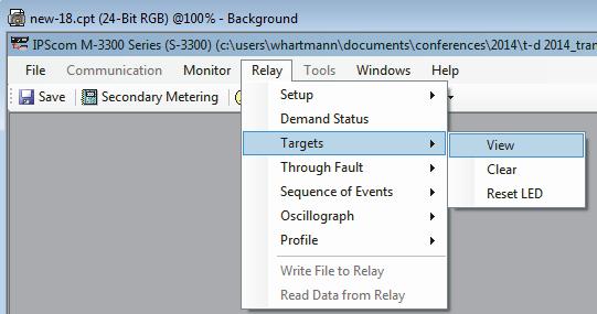
244 Retrieve Target Log 244
Improving Transformer Protection
 Omaha, NB October 12, 2017 Improving Transformer Protection Wayne Hartmann VP, Customer Excellence Senior Member, IEEE Wayne Hartmann Senior VP, Customer Excellence Speaker Bio whartmann@beckwithelectric.com
Hands On Relay School Open Lecture Transformer Differential Protection Scott Cooper
 Hands On Relay School Open Lecture Transformer Differential Protection Scott Cooper Transformer Differential Protection ntroduction: Transformer differential protection schemes are ubiquitous to almost
Hands On Relay School Open Lecture Transformer Differential Protection Scott Cooper
 Hands On Relay School Open Lecture Transformer Differential Protection Scott Cooper Transformer Differential Protection ntroduction: Transformer differential protection schemes are ubiquitous to almost
Transformer Protection
 Transformer Protection Transformer Protection Outline Fuses Protection Example Overcurrent Protection Differential Relaying Current Matching Phase Shift Compensation Tap Changing Under Load Magnetizing
Generator Protection GENERATOR CONTROL AND PROTECTION
 Generator Protection Generator Protection Introduction Device Numbers Symmetrical Components Fault Current Behavior Generator Grounding Stator Phase Fault (87G) Field Ground Fault (64F) Stator Ground Fault
Transformer Protection Principles
 Transformer Protection Principles 1. Introduction Transformers are a critical and expensive component of the power system. Due to the long lead time for repair of and replacement of transformers, a major
Modern transformer relays include a comprehensive set of protective elements to protect transformers from faults and abnormal operating conditions
 1 Transmission transformers are important links in the bulk power system. They allow transfer of power from generation centers, up to the high-voltage grid, and to bulk electric substations for distribution
Detecting and Managing Geomagnetically Induced Currents With Relays
 Detecting and Managing Geomagnetically Induced Currents With Relays Copyright SEL 2013 Transformer Relay Connections Voltage Current Control RTDs Transformer Protective Relay Measures differential current
COPYRIGHTED MATERIAL. Index
 Index Note: Bold italic type refers to entries in the Table of Contents, refers to a Standard Title and Reference number and # refers to a specific standard within the buff book 91, 40, 48* 100, 8, 22*,
www. ElectricalPartManuals. com Transformer Differential Relay MD32T Transformer Differential Relay
 Transformer Differential Relay The MD3T Transformer Differential Relay is a member of Cooper Power Systems Edison line of microprocessor based protective relays. The MD3T relay offers the following functions:
Catastrophic Relay Misoperations and Successful Relay Operation
 Catastrophic Relay Misoperations and Successful Relay Operation Steve Turner (Beckwith Electric Co., Inc.) Introduction This paper provides detailed technical analysis of several catastrophic relay misoperations
System Protection and Control Subcommittee
 Power Plant and Transmission System Protection Coordination Volts Per Hertz (24), Undervoltage (27), Overvoltage (59), and Under/Overfrequency (81) Protection System Protection and Control Subcommittee
This webinar brought to you by the Relion product family Advanced protection and control IEDs from ABB
 This webinar brought to you by the Relion product family Advanced protection and control IEDs from ABB Relion. Thinking beyond the box. Designed to seamlessly consolidate functions, Relion relays are smarter,
Protecting power transformers from common adverse conditions
 Protecting power transformers from common adverse conditions by Ali Kazemi, and Casper Labuschagne, Schweitzer Engineering Laboratories Power transformers of various size and configuration are used throughout
Transformer Protection
 Transformer Protection Nature of transformer faults TXs, being static, totally enclosed and oil immersed develop faults only rarely but consequences large. Three main classes of faults. 1) Faults in Auxiliary
System Protection and Control Subcommittee
 Power Plant and Transmission System Protection Coordination Reverse Power (32), Negative Sequence Current (46), Inadvertent Energizing (50/27), Stator Ground Fault (59GN/27TH), Generator Differential (87G),
ENOSERV 2014 Relay & Protection Training Conference Course Descriptions
 ENOSERV 2014 Relay & Protection Training Conference Course Descriptions Day 1 Generation Protection/Motor Bus Transfer Generator Protection: 4 hours This session highlights MV generator protection and
Transformer protection IED RET 670
 Gunnar Stranne Transformer protection IED RET 670 Santiago Septiembre 5, 2006 1 Transformer protection IED RET670 2 Introduction features and applications Differential protection functions Restricted Earth
Sequence Networks p. 26 Sequence Network Connections and Voltages p. 27 Network Connections for Fault and General Unbalances p. 28 Sequence Network
 Preface p. iii Introduction and General Philosophies p. 1 Introduction p. 1 Classification of Relays p. 1 Analog/Digital/Numerical p. 2 Protective Relaying Systems and Their Design p. 2 Design Criteria
www. ElectricalPartManuals. com Generator Differential Relay MD32G Rotating Machine Differential Relay
 Generator Differential Relay The MD3G Rotating Machine Differential Relay is a member of Cooper Power Systems Edison line of microprocessor based protective relays. The MD3G relay offers the following
Transformer Fault Categories
 Transformer Fault Categories 1. Winding and terminal faults 2. Sustained or uncleared external faults 3. Abnormal operating conditions such as overload, overvoltage and overfluxing 4. Core faults 1 (1)
IMPROVEMENTS IN PROTECTION AND COMMISSIONING OF DIGITAL TRANSFORMER RELAYS AT MEDIUM VOLTAGE INDUSTRIAL FACILITIES
 IMPOVEMENTS IN POTECTION AND COMMISSIONING OF DIGITAL TANSFOME ELAYS AT MEDIUM VOLTAGE INDUSTIAL FACILITIES Copyright Material IEEE Paper No. PCIC-AN84 Charles J. Mozina, P.E. Life Fellow Member, IEEE
Waterpower '97. Upgrading Hydroelectric Generator Protection Using Digital Technology
 Waterpower '97 August 5 8, 1997 Atlanta, GA Upgrading Hydroelectric Generator Protection Using Digital Technology Charles J. Beckwith Electric Company 6190-118th Avenue North Largo, FL 33773-3724 U.S.A.
Protection Basics Presented by John S. Levine, P.E. Levine Lectronics and Lectric, Inc GE Consumer & Industrial Multilin
 Protection Basics Presented by John S. Levine, P.E. Levine Lectronics and Lectric, Inc. 770 565-1556 John@L-3.com 1 Protection Fundamentals By John Levine 2 Introductions Tools Outline Enervista Launchpad
Power System Protection
 I Power System Protection Arun Phadke Virginia Polytechnic Institute 1 Transfor mer Protection Alexander Apostolov, John Apple yard, Ahmed Elneweihi, Robert Haas, and Glenn W Swift 1-1 Ty pes of Transformer
Problems connected with Commissioning of Power Transformers
 Problems connected with Commissioning of Power Transformers ABSTRACT P Ramachandran ABB India Ltd, Vadodara, India While commissioning large Power Transformers, certain abnormal phenomena were noticed.
Numbering System for Protective Devices, Control and Indication Devices for Power Systems
 Appendix C Numbering System for Protective Devices, Control and Indication Devices for Power Systems C.1 APPLICATION OF PROTECTIVE RELAYS, CONTROL AND ALARM DEVICES FOR POWER SYSTEM CIRCUITS The requirements
Protection of a 138/34.5 kv transformer using SEL relay
 Scholars' Mine Masters Theses Student Theses and Dissertations Fall 2016 Protection of a 138/34.5 kv transformer using SEL 387-6 relay Aamani Lakkaraju Follow this and additional works at: http://scholarsmine.mst.edu/masters_theses
PROTECTION OF TRANSFORMERS M-3311A TEST PLAN
 PROTECTION OF TRANSFORMERS M-3311A TEST PLAN Chuck Mozina -- is a Consultant, Protection and Protection Systems for Beckwith Electric and resides in Palm Harbor (near Tampa), Florida.. He is a Life Fellow
Substation applications
 Substation applications To make it easy to choose the right for a protection application, the most typical applications are presented with the type of for them. Each sample application is presented by:
Pinhook 500kV Transformer Neutral CT Saturation
 Russell W. Patterson Tennessee Valley Authority Presented to the 9th Annual Fault and Disturbance Analysis Conference May 1-2, 26 Abstract This paper discusses the saturation of a 5kV neutral CT upon energization
NERC Protection Coordination Webinar Series June 23, Phil Tatro
 Power Plant and Transmission System Protection Coordination Volts Per Hertz (24), Undervoltage (27), Overvoltage (59), and Under/Overfrequency (81) Protection NERC Protection Coordination Webinar Series
PD300. Transformer, generator and motor protection Data sheet
 PD300 Transformer, generator and motor protection Data sheet DSE_PD300_eng_AO No part of this publication may be reproduced by whatever means without the prior written permission of Ingeteam T&D. One of
Power Plant and Transmission System Protection Coordination Fundamentals
 Power Plant and Transmission System Protection Coordination Fundamentals NERC Protection Coordination Webinar Series June 2, 2010 Jon Gardell Agenda 2 Objective Introduction to Protection Generator and
PJM Manual 07:: PJM Protection Standards Revision: 2 Effective Date: July 1, 2016
 PJM Manual 07:: PJM Protection Standards Revision: 2 Effective Date: July 1, 2016 Prepared by System Planning Division Transmission Planning Department PJM 2016 Table of Contents Table of Contents Approval...6
TECHNICAL BULLETIN 004a Ferroresonance
 May 29, 2002 TECHNICAL BULLETIN 004a Ferroresonance Abstract - This paper describes the phenomenon of ferroresonance, the conditions under which it may appear in electric power systems, and some techniques
thepower to protect the power to protect i-gard LITERATURE Low and medium voltage
 thepower to protect i-gard LITERATURE Low and medium voltage distribution systems Arc Flash Hazards and High Resistance Grounding Grounding of Standby and Emergency Power Systems Neutral Grounding Resistors
NERC Protection Coordination Webinar Series July 15, Jon Gardell
 Power Plant and Transmission System Protection Coordination Reverse Power (32), Negative Sequence Current (46), Inadvertent Energizing (50/27), Stator Ground Fault (59GN/27TH), Generator Differential (87G),
Unit Auxiliary Transformer (UAT) Relay Loadability Report
 Relay Loadability Report") Background and Objective Reliability Standard, PRC 025 1 Generator Relay Loadability (standard), developed under NERC Project 2010 13.2 Phase 2 of Relay Loadability: Generation, was adopted by the NERC
Background and Objective Reliability Standard, PRC 025 1 Generator Relay Loadability (standard), developed under NERC Project 2010 13.2 Phase 2 of Relay Loadability: Generation, was adopted by the NERC
NERC Protection Coordination Webinar Series June 16, Phil Tatro Jon Gardell
 Power Plant and Transmission System Protection Coordination Phase Distance (21) and Voltage-Controlled or Voltage-Restrained Overcurrent Protection (51V) NERC Protection Coordination Webinar Series June
Impact of transient saturation of Current Transformer during cyclic operations Analysis and Diagnosis
 1 Impact of transient saturation of Current Transformer during cyclic operations Analysis and Diagnosis BK Pandey, DGM(OS-Elect) Venkateswara Rao Bitra, Manager (EMD Simhadri) 1.0 Introduction: Current
BUS2000 Busbar Differential Protection System
 BUS2000 Busbar Differential Protection System Differential overcurrent system with percentage restraint protection 1 Typical Busbar Arrangements Single Busbar Double Busbar with Coupler Breaker and a Half
CHAPTER 3 REVIEW OF POWER TRANSFORMER PROTECTION SCHEMES
 CHAPTER 3 REVIEW OF POWER TRANSFORMER PROTECTION SCHEMES 3.1. Introduction Power Transformer is the nerve centre of any power distribution system. The capacity of power transformers is generally decided
Power System Protection. Dr. Lionel R. Orama Exclusa, PE Week 3
 Power System Protection Dr. Lionel R. Orama Exclusa, PE Week 3 Operating Principles: Electromagnetic Attraction Relays Readings-Mason Chapters & 3 Operating quantities Electromagnetic attraction Response
Protection of Electrical Networks. Christophe Prévé
 Protection of Electrical Networks Christophe Prévé This Page Intentionally Left Blank Protection of Electrical Networks This Page Intentionally Left Blank Protection of Electrical Networks Christophe Prévé
g GE POWER MANAGEMENT
 745 FREQUENTLY ASKED QUESTIONS 1 I get a communication error with the relay when I try to store a setpoint. This error can occur for several different reasons. First of all, verify that the address is
Power systems Protection course
 Al-Balqa Applied University Power systems Protection course Department of Electrical Energy Engineering 1 Part 5 Relays 2 3 Relay Is a device which receive a signal from the power system thought CT and
Verifying Transformer Differential Compensation Settings
 Verifying Transformer Differential Compensation Settings Edsel Atienza and Marion Cooper Schweitzer Engineering Laboratories, Inc. Presented at the 6th International Conference on Large Power Transformers
Protective Relays Digitrip 3000
 New Information Technical Data Effective: May 1999 Page 1 Applications Provides reliable 3-phase and ground overcurrent protection for all voltage levels. Primary feeder circuit protection Primary transformer
NO WARRANTIES OF ANY KIND ARE IMPLIED ON THE INFORMATION CONTAINED IN THIS DOCUMENT.
 MODBUS/BECO2200-M3425A Communication Data Base for M-3425A Integrated Protection System Device I.D. = 150 Specifications presented herein are thought to be accurate at the time of publication but are subject
This webinar brought to you by The Relion Product Family Next Generation Protection and Control IEDs from ABB
 This webinar brought to you by The Relion Product Family Next Generation Protection and Control IEDs from ABB Relion. Thinking beyond the box. Designed to seamlessly consolidate functions, Relion relays
Power Plant and Transmission System Protection Coordination
 Technical Reference Document Power Plant and Transmission System Protection Coordination NERC System Protection and Control Subcommittee Revision 1 July 2010 Table of Contents 1. Introduction... 1 1.1.
Bus Protection Fundamentals
 Bus Protection Fundamentals Terrence Smith GE Grid Solutions 2017 Texas A&M Protective Relay Conference Bus Protection Requirements High bus fault currents due to large number of circuits connected: CT
Electrical Protection System Design and Operation
 ELEC9713 Industrial and Commercial Power Systems Electrical Protection System Design and Operation 1. Function of Electrical Protection Systems The three primary aims of overcurrent electrical protection
KNOW MORE ABOUT THE TRANSFORMERS. Glossary Transformers
 KNOW MORE ABOUT THE TRANSFORMERS Glossary Transformers Ambient temperature The existing temperature of the atmosphere surrounding a transformer installation. Ampere The practical unit of electric current.
NTG MULTIFUNCTON GENERATOR PROTECTION RELAY. NTG-Slide
 NTG MULTIFUNCTON GENERATOR PROTECTION RELAY 1 NTG Digital protection relay that integrates a number of functions required r for the protection of generators. It is used in power stations from gas, steam,
Excitation Systems THYRIPART. Compound-Excitation System for Synchronous Generators. Power Generation
 Excitation Systems Compound-Excitation System for Synchronous Generators Power Generation Operating Characteristics Load dependent Short circuit supporting Low voltage gradient dv/dt Black start capability
DIGITAL EXCITATION SYSTEM PROVIDES ENHANCED PERFORMANCE AND IMPROVED DIAGNOSTICS
 DIGITAL EXCITATION SYSTEM PROVIDES ENHANCED PERFORMANCE AND IMPROVED DIAGNOSTICS C. Allan Morse Member, IEEE Eaton / Cutler Hammer 221 Heywood Road Arden, NC 2874 C. Richard Mummert Member, IEEE Eaton
7SG14 Duobias-M Transformer Protection
 7SG14 Duobias-M Transformer Protection Document Release History This document is issue 2010/02. The list of revisions up to and including this issue is: Pre release Revision Date Change 2010/02 Document
PIPSPC. Prepared by Eng: Ahmed Safie Eldin. And. Introduction. Protection Control. Practical. System. Power
 PIPSPC Practical Introduction Power System Protection Control Practical Introduction To Power System Protection And Control Prepared by Eng: Ahmed Safie Eldin 2005 Contents POWER SYSTEMS PRINCIPALS. 1
Advanced Applications of Multifunction Digital Generator Protection
 Advanced Applications of Multifunction Digital Generator Protection Charles J. Mozina Beckwith Electric Company 6190-118th Avenue North Largo, FL 33773-3724 U.S.A. Abstract: The protection of generators
1
 Guidelines and Technical Basis Introduction The document, Power Plant and Transmission System Protection Coordination, published by the NERC System Protection and Control Subcommittee (SPCS) provides extensive
IDAHO PURPA GENERATOR INTERCONNECTION REQUEST (Application Form)
") IDAHO PURPA GENERATOR INTERCONNECTION REQUEST (Application Form) Transmission Provider: IDAHO POWER COMPANY Designated Contact Person: Jeremiah Creason Address: 1221 W. Idaho Street, Boise ID 83702 Telephone
IDAHO PURPA GENERATOR INTERCONNECTION REQUEST (Application Form) Transmission Provider: IDAHO POWER COMPANY Designated Contact Person: Jeremiah Creason Address: 1221 W. Idaho Street, Boise ID 83702 Telephone
PRC Generator Relay Loadability. Guidelines and Technical Basis Draft 4: (June 10, 2013) Page 1 of 75
 Page 1 of 75") PRC-025-1 Introduction The document, Power Plant and Transmission System Protection Coordination, published by the NERC System Protection and Control Subcommittee (SPCS) provides extensive general discussion
PRC-025-1 Introduction The document, Power Plant and Transmission System Protection Coordination, published by the NERC System Protection and Control Subcommittee (SPCS) provides extensive general discussion
PRC Generator Relay Loadability. Guidelines and Technical Basis Draft 5: (August 2, 2013) Page 1 of 76
 Page 1 of 76") PRC-025-1 Introduction The document, Power Plant and Transmission System Protection Coordination, published by the NERC System Protection and Control Subcommittee (SPCS) provides extensive general discussion
PRC-025-1 Introduction The document, Power Plant and Transmission System Protection Coordination, published by the NERC System Protection and Control Subcommittee (SPCS) provides extensive general discussion
Embedded Generation Connection Application Form
 Embedded Generation Connection Application Form This Application Form provides information required for an initial assessment of the Embedded Generation project. All applicable sections must be completed
Testing Numerical Transformer Differential Relays
 Feature Testing Numerical Transformer Differential Relays Steve Turner Beckwith Electric Co., nc. ntroduction Numerical transformer differential relays require careful consideration as to how to test properly.
GENERATOR INTERCONNECTION APPLICATION Category 5 For All Projects with Aggregate Generator Output of More Than 2 MW
 GENERATOR INTERCONNECTION APPLICATION Category 5 For All Projects with Aggregate Generator Output of More Than 2 MW ELECTRIC UTILITY CONTACT INFORMATION Consumers Energy Interconnection Coordinator 1945
Power Plant and Transmission System Protection Coordination
 Agenda Item 5.h Attachment 1 A Technical Reference Document Power Plant and Transmission System Protection Coordination Draft 6.9 November 19, 2009 NERC System Protection and Control Subcommittee November
UProtection Requirements. Ufor a Large scale Wind Park. Shyam Musunuri Siemens Energy
 UProtection Requirements Ufor a Large scale Wind Park Shyam Musunuri Siemens Energy Abstract: In the past wind power plants typically had a small power rating when compared to the strength of the connected
Earth Fault Protection
 Earth Fault Protection Course No: E03-038 Credit: 3 PDH Velimir Lackovic, Char. Eng. Continuing Education and Development, Inc. 9 Greyridge Farm Court Stony Point, NY 10980 P: (877) 322-5800 F: (877) 322-4774
Forward to the Basics: Selected Topics in Distribution Protection
 Forward to the Basics: Selected Topics in Distribution Protection Lee Underwood and David Costello Schweitzer Engineering Laboratories, Inc. Presented at the IEEE Rural Electric Power Conference Orlando,
Unit Protection Differential Relays
 Unit Protection PROF. SHAHRAM MONTASER KOUHSARI Current, pu Current, pu Protection Relays - BASICS Note on CT polarity dots Through-current: must not operate Internal fault: must operate The CT currents
OPEN-PHASE DETECTION TECHNIQUES FOR CRITICAL STANDBY SUPPLIES
 OPEN-PHASE DETECTION TECHNIQUES FOR CRITICAL STANDBY SUPPLIES U AJMAL, GE Grid Solutions UK Ltd, usman.ajmal@ge.com S SUBRAMANIAN, GE Grid Solutions UK Ltd, sankara.subramanian@ge.com H Ha GE Grid Solutions
POWER TRANSFORMER SPECIFICATION, DESIGN, QUALITY CONTROL AND TESTING 18 MARCH 2009
 POWER TRANSFORMER SPECIFICATION, DESIGN, QUALITY CONTROL AND TESTING 18 MARCH 2009 Nkosinathi Buthelezi Senior Consultant: Power Transformers and Reactors Presentation Content Standardization of Power
Stabilized Differential Relay SPAD 346. Product Guide
 Issued: July 1998 Status: Updated Version: D/21.03.2006 Data subject to change without notice Features Integrated three-phase differential relay, three-phase overcurrent relay and multiconfigurable earth-fault
NOVEL PROTECTION SYSTEMS FOR ARC FURNACE TRANSFORMERS
 NOVEL PROTECTION SYSTEMS FOR ARC FURNACE TRANSFORMERS Ljubomir KOJOVIC Cooper Power Systems - U.S.A. Lkojovic@cooperpower.com INTRODUCTION In steel facilities that use Electric Arc Furnaces (EAFs) to manufacture
Overcurrent and Overload Protection of AC Machines and Power Transformers
 Exercise 2 Overcurrent and Overload Protection of AC Machines and Power Transformers EXERCISE OBJECTIVE When you have completed this exercise, you will understand the relationship between the power rating
Modular range of digital protection relays
 S e p a m s e r i e s 2 0, 4 0, 8 0 Modular range of digital protection relays Fast Dependable Simple Fast response Maximum dependability Your electrical equipment is under control. With Sepam protection
2015 Relay School Bus Protection Mike Kockott March, 2015
 2015 Relay School Bus Protection Mike Kockott March, 2015 History of Bus Protection Circulating current differential (1900s) High impedance differential (1940s) Percentage restrained differential (1960s)
Embedded Generation Connection Application Form
 Embedded Generation Connection Application Form This Application Form provides information required for an initial assessment of the Embedded Generation project. All applicable sections must be completed
1 INTRODUCTION 1.1 PRODUCT DESCRIPTION
 GEK-00682D INTRODUCTION INTRODUCTION. PRODUCT DESCRIPTION The MDP Digital Time Overcurrent Relay is a digital, microprocessor based, nondirectional overcurrent relay that protects against phase-to-phase
Training Fees 3,300$ per participant including Materials/Handouts, Tea/Coffee Refreshments & International Buffet Lunch.
 Training Title POWER TRANSFORMERS Training Duration 5 days Training Venue and Dates Power transformers 5 20-24 May $3,300 Abu Dhabi In any of the 5 star hotel. The exact venue will be informed soon. Training
Busbars and lines are important elements
 CHAPTER CHAPTER 23 Protection of Busbars and Lines 23.1 Busbar Protection 23.2 Protection of Lines 23.3 Time-Graded Overcurrent Protection 23.4 Differential Pilot-Wire Protection 23.5 Distance Protection
Optimizing HV Capacitor Bank Design, Protection, and Testing Benton Vandiver III ABB Inc.
 Optimizing HV Capacitor Bank Design, Protection, and Testing Benton Vandiver III ABB Inc. Abstract - This paper will discuss in detail a capacitor bank protection and control scheme for >100kV systems
NERC Requirements for Setting Load-Dependent Power Plant Protection: PRC-025-1
 NERC Requirements for Setting Load-Dependent Power Plant Protection: PRC-025-1 Charles J. Mozina, Consultant Beckwith Electric Co., Inc. www.beckwithelectric.com I. Introduction During the 2003 blackout,
NERC Protection Coordination Webinar Series June 9, Phil Tatro Jon Gardell
 Power Plant and Transmission System Protection Coordination GSU Phase Overcurrent (51T), GSU Ground Overcurrent (51TG), and Breaker Failure (50BF) Protection NERC Protection Coordination Webinar Series
Appendix C-1. Protection Requirements & Guidelines Non-Utility Generator Connection to Okanogan PUD
 A. Introduction Appendix C-1 Protection Requirements & Guidelines to Okanogan PUD The protection requirements identified in this document apply to Non-Utility Generating (NUG) facilities, Independent Power
Basic Principles and Operation of Transformer
 Basic Principles and Operation of Transformer CONSTRUCTIONAL ASPECTS Cores In order to enhance core s magnetic properties, it is constructed from an iron and silicon mixture (alloy). The magnetic core
A Tutorial on the Application and Setting of Collector Feeder Overcurrent Relays at Wind Electric Plants
 A Tutorial on the Application and Setting of Collector Feeder Overcurrent Relays at Wind Electric Plants Martin Best and Stephanie Mercer, UC Synergetic, LLC Abstract Wind generating plants employ several
Relay-assisted commissioning
 Relay-assisted commissioning by Casper Labuschagne and Normann Fischer, Schweitzer Engineering Laboratories (SEL) Power transformer differential relays were among the first protection relays to use digital
7. INSPECTION AND TEST PROCEDURES
 7.1 Switchgear and Switchboard Assemblies A. Visual and Mechanical Inspection 1. Compare equipment nameplate data with drawings and specifications. 2. Inspect physical and mechanical condition. 3. Inspect
Tertiary Winding Design in wye-wye Connected Transformers Restricted Siemens Energy 2013 All rights reserved.
 Pomona, CA, May 24 & 25, 2016 Tertiary Winding Design in wye-wye Connected Transformers Scope of Presentation > Tertiary vs. Stabilizing Winding? Tertiary vs. Stabilizing Winding? Need for Stabilizing
Generator Advanced Concepts
 Generator Advanced Concepts Common Topics, The Practical Side Machine Output Voltage Equation Pitch Harmonics Circulating Currents when Paralleling Reactances and Time Constants Three Generator Curves
Effects of Harmonic Distortion I
 Effects of Harmonic Distortion I Harmonic currents produced by nonlinear loads are injected back into the supply systems. These currents can interact adversely with a wide range of power system equipment,
EASUN REYROLLE LIMITED
 OCTOBER 2003 APPLICATION AND COMMISSIONING MANUAL FOR NUMERICAL BIASED DIFFERENTIAL PROTECTION RELAY TYPE - MIB202 EASUN REYROLLE LIMITED 1 ISSUE NO : 1 st Issue DATE OF ISSUE : 01-10 - 2003 DEPARTMENT
Motor Protection. May 31, Tom Ernst GE Grid Solutions
 Motor Protection May 31, 2017 Tom Ernst GE Grid Solutions Motor Relay Zone of Protection -Electrical Faults -Abnormal Conditions -Thermal Overloads -Mechanical Failure 2 Setting of the motor protection
ISO Rules Part 500 Facilities Division 502 Technical Requirements Section Wind Aggregated Generating Facilities Technical Requirements
 Applicability 1(1) Section 502.1 applies to the ISO, and subject to the provisions of subsections 1(2), (3) and (4) to any: (a) a new wind aggregated generating facility to be connected to the transmission
Improve asset protection and utilization
 QUALITROL 509 ITM Intelligent transformer monitor Improve asset protection and utilization Immediately know your transformer health with TransLife Optimize loading and equipment life Simplify root cause
These drawings and single line diagrams provide an outlook of Basler Electric solutions for Excitation System installations and retrofit
 BSLER ELECTRIC DECS EXCITTION SYSTEMS For Retrofitting solutions and New installations These drawings and single line diagrams provide an outlook of Basler Electric solutions for Excitation System installations