Power System Protection Manual
|
|
|
- Malcolm Ross
- 6 years ago
- Views:
Transcription
1 Power System Protection Manual Note: This manual is in the formative stage. Not all the experiments have been covered here though they are operational in the laboratory. When the full manual is ready, we will make it available here. Electrical Engineering Department, Birla Vishvakarma Mahavidyalaya (BVM) Engineering College, Vallabh Vidyanagar, Gujarat, India Pin:
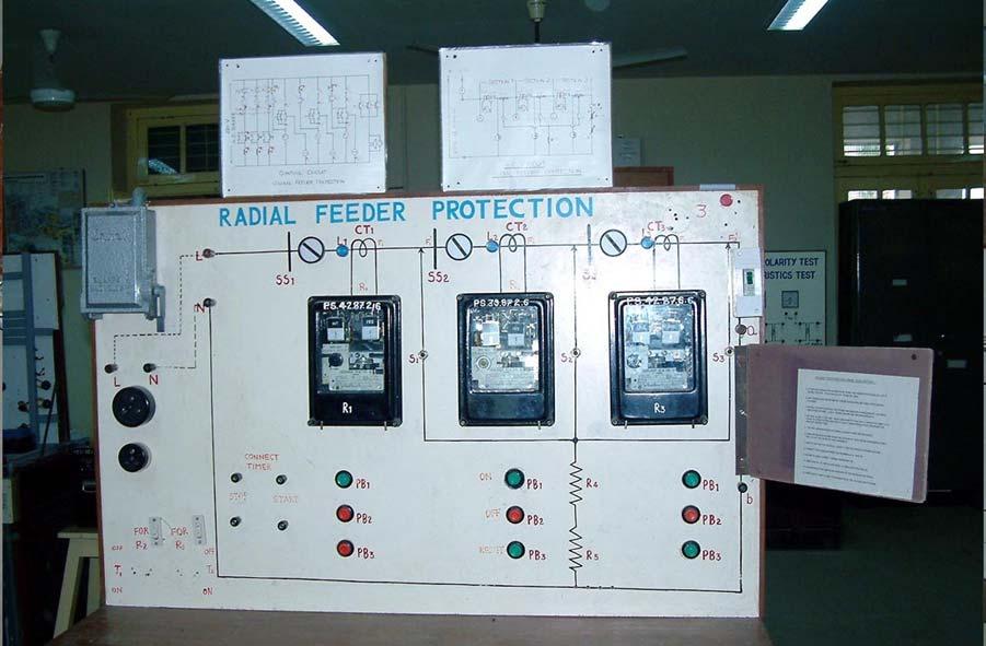
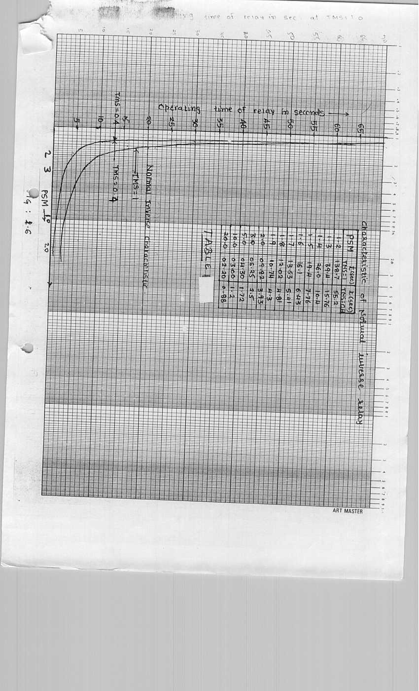
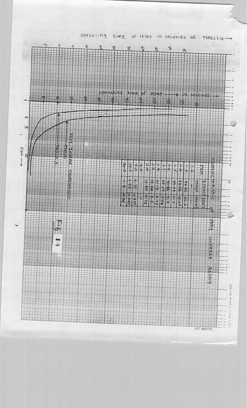
2 Experiment No-1 Radial Feeder Protection Theoretical Background: Whole of the power system can be subdivided in to number of radial feeders fed from one end. Generally such radial feeders are protected by over current and earth fault relays used as primary relays for 11 kv and 66 kv lines. For lines of voltage rating beyond 66 kv, distance protection is applied as a primary protection whereas over current and earth fault relays are used as back up relays. A simplified radial feeder network without transformers (in actual practice transformers do exist at substations) is shown in single line diagram of fig. 1.1 below. Section I Section II Section III S So urce A B C D Transmission Line R1 R2 R3 Fuse Fig A Typical Radial Transmission Line To Load If the fault occurs in distribution network, fuse should isolate the faulty section. Should the fuse fail, relay R 3 shall give back-up protection. Relays R 1, R 2, and R 3 act as primary relays for faults in section I, section I, and section III respectively. If fault in section III is not cleared by relaying scheme at relaying point R 3, relay R 2 will act as a back-up. Similarly back-up protection is provided by relay R 1 for faults in section II. A,B, C and D are substations in fig Generally Inverse time overcurrent relays with Definite Minimum Time feature (IDMT relays) are used in practice. There are many types of such relays available in relaymarket, viz. normal inverse relays, very inverse relays and extremely inverse relays. The characteristics of these relays are shown in fig The other types of o/c relays are 3 second relay and 1.3 second relay. This means the time of operation of the relay is either 3 or 1.3 second at Plug Setting Multiplier (PSM) equal to 10. Long time inverse relays are used for o/c cum overload application. Voltage restrains o/c relays have their own application. Very inverse relays are less prone to the ratio Z S /Z L. Extremely inverse relays are yet better. Very inverse relays are faster in operation for close-in faults yet maintaining the discrimination with fuse and other relays. Extremely inverse relays are more meritorious 1

3 in this aspect too. Instantaneous o/c relays are not immune to Z S /Z L ratio. Definite time o/c relays are 100 % immune to this ratio. Very inverse relays can be used with an additional advantage while protecting a machine or a transformer as they match with the heating characteristic of equipment better than their normal inverse equivalent. Extremely inverse relays can best co-ordinate with the fuse characteristic. The aim of this experiment is to reveal these facts experimentally. Fig. 1.2 Normal, Very and Extremely Inverse Characteristics L aboratory Simulations: Referring to a.c. circuit of fig a live model of a radial feeder fed from one end can be self-understood. Section - I Section - II Section - III A C1-1 C2-1 C3-1 10/5 9Ω 10/5 9Ω 10/5 230 V, 50 Hz 1-phase, ac supply V R1 R2 R3 S1 S2 S3 MCB 550Ω (Load) 18Ω (Fault resistance) Fig. 1.3 Main AC Circuit in the Experiment. 2
4 This is only a single phase version of a radial feeder. Transmission lines are simulated by 9 ohms resistors as we are studying only the steady state behavior of the relays and the network. Circuit breakers are simulated by contactors. Distributor is protected by a 0.5 Amp M.C.B. Semaphore indicators on the panel show the status of the contactor(whether ON or OFF). Visual neon lamp indictors are also used. Faults in different sections can be created by switches S1, S2 and S3. Fault limiting resistance of 18 ohms is used for practical purposes only, as otherwise the source would get shorted for a fault at start of the first section. For fault in distributor, Ohmic value of load rheostats can be decreased. MCB simulates fuses or MCCB. In actual practice C.T. secondary rated current (1 Amp or 5 Amp) and relay rating should be same. Here C.T. secondary rating is 5 Amp and relay rating is 1 Amp. This is contradicting the practice for for practical purpose. A1-1 A2-1 A3-1 PB-3 PB-3 T2 PB-3 T V DC Supply L1 L2 L3 C1 C2 C1-2 C2-2 PB-1 PB-1 PB-2 PB-2 C3 A1-2 C3-2 PB-1 PB-2 A1 R1-1 A2-2 A2 R2-1 A3-2 A3 R3-1 (a) C1-3 C2-3 C V DC Supply S-1 S-2 S-3 bulb Buzzer A1-3 A2-3 A3-3 S-1, S-2, S-3 are semaphore indicators (b) Fig. 1.4 Control Circuit in the Experiment. 3
5 Referring to control circuit of figure 1.4(a) and (b), any section can be manually charged or made off using start (PB 1 ) and stop (PB 2 ) push buttons, which are spring loaded. On occurrence of fault, the corresponding section relay will operate and the concerned auxiliary relay A 1, A 2 or A 3 will energize giving signal to the concerned contactor and making it off. This will also activate the buzzer and bulb which can be reset using Accept pushbutton PB 3. Back up can be shown by using switches T 1 and T 2 on the panel. Time of operation of relays can be measured by a time interval counter connected as shown in fig. 1.4 (c). S1 A1-4 S2 S3 A2-4 A3-4 To timer To timer Start Stop terminals terminals (c) Fig. 1.4 Control Circuit in the Experiment. O bservations and calculations: 1. Measure the fault currents for extreme faults in sections I, II and III by adjusting the corresponding rheostat in minimum (zero resistance) and maximum (full resistance) positions and using the corresponding fault-switch S 1, S 2, or S 3 (refer fig. 1.3). Maximum fault currents in sections I, II and III are denoted by F 1, F 2, F 3 respectively and the minimum fault currents by F 1, F 2, F 3 respectively. Deactivate the relays for this purpose. Record the readings in table 1: Fault Location F 1 F 1 F 2 F 2 F 3 F 3 Fault Current (A) Table:1.1 Measured fault currents for extreme faults in each section 2. Calculate the plug settings (or Tap Value) of relays R 1, R 2 and R 3. (Plug settings will be same irrespective of type of relays ). For this purpose, assume the number of distributors each of 0.5 Amp rating from the following possibilities (The experiment 4
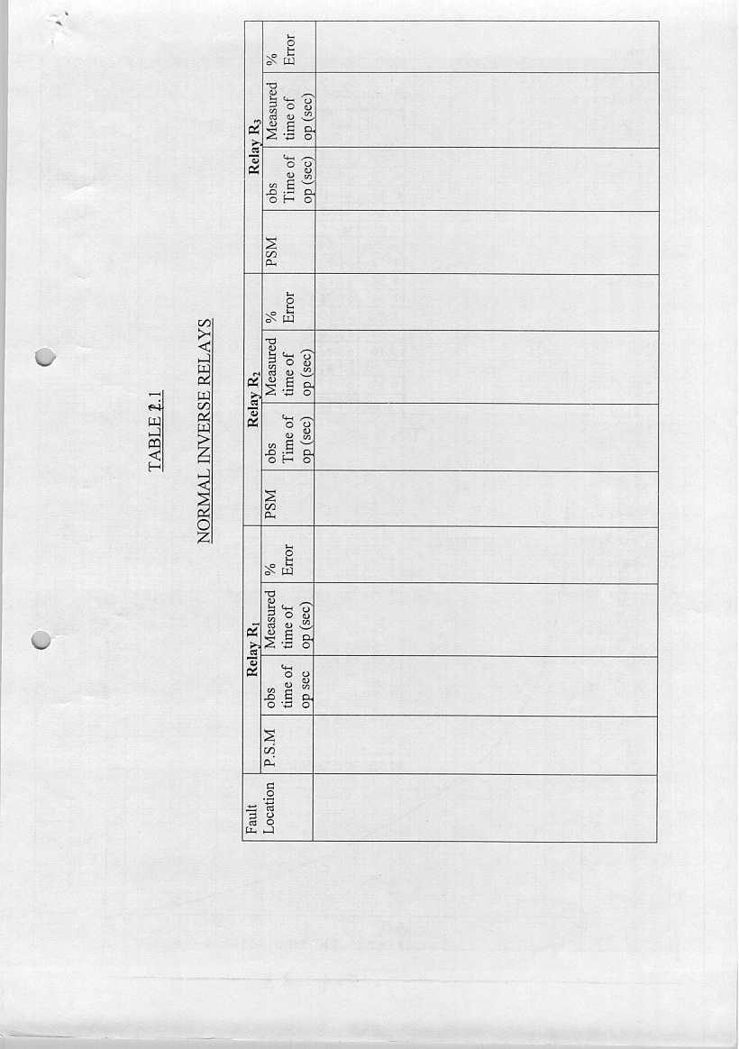
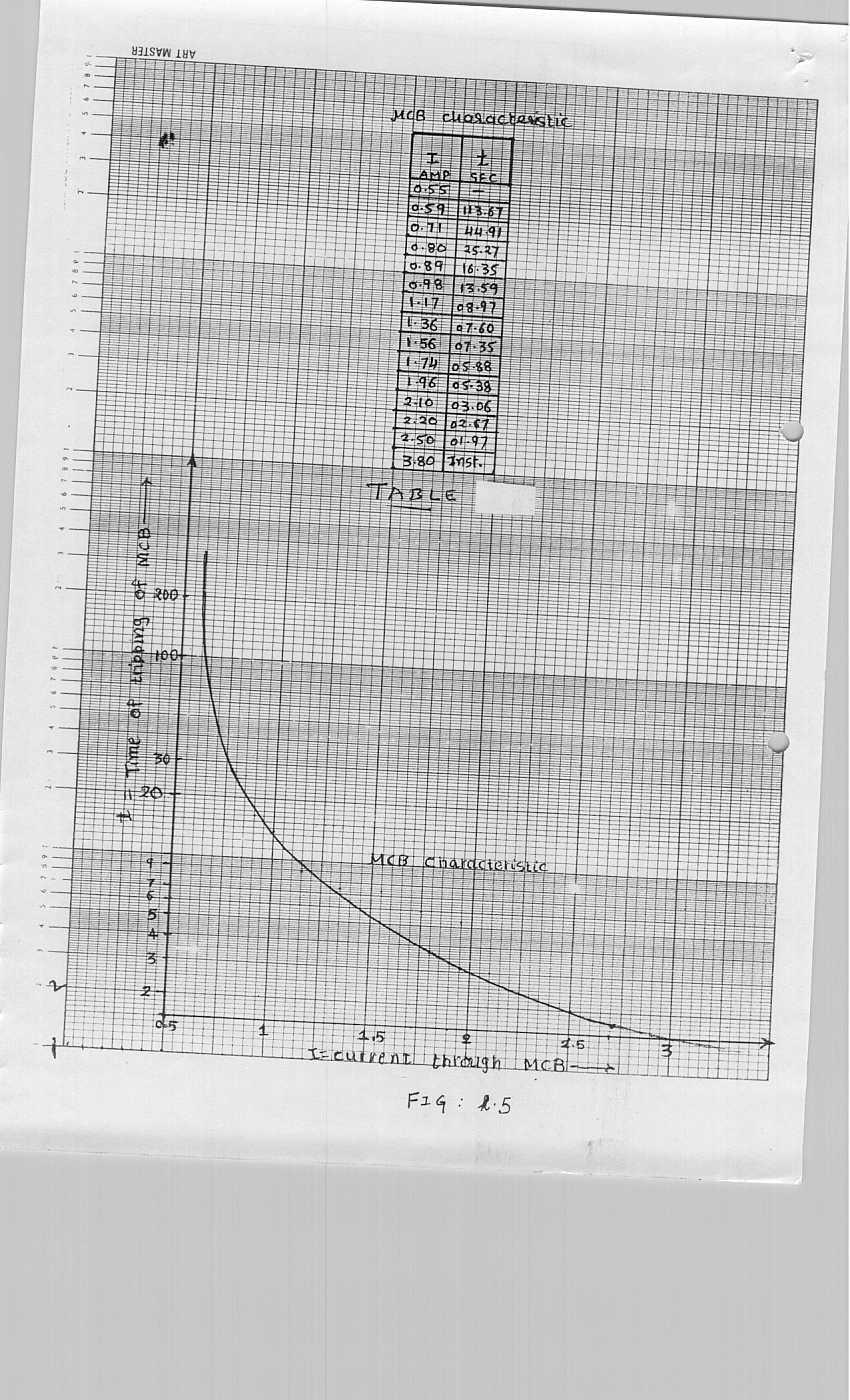
6 3. is a simulation and hence the distributor current is 0.5 Amp. In actual practice it may be 500 Amp or more or less): Number of distributors: 1, 2, 3 or 4. (Calculations of the plug setting shall be done w.r.t. following considerations.) (I) The plug setting shall be more than or equal to the maximum full-load current passing through the relay. (II) The pick up of the relay varies from 1.05 to 1.3 times the plug setting of the relay. (III) For back up, relay R 1 shall reach for the fault F 2 and R 2 for the fault F 3. Time Settings. (Normal Inverse Relays) For deciding time-settings, co-ordinate the characteristic of relay R 3 with that of an MCB.( Refer figures 1.5 and 1.6.) Use discriminating time-interval of 1.0 second between two characteristics. This will decide TMS of R 3. Why discrimination time of 1.0 second? (Try answer to this question.) For coordinating R 2 with R 3, use the worst possible current to decide TMS of R 2 (F 3 in table:1.1). Similarly decide TMS of R 1 by using F 2 and setting of R 2. Use discriminating time interval between two successive relays as 0.4 seconds (why 0.4 seconds?) for these calculations. Tabulate the results as follows: Normal inverse Relays. Relay R 1 R 2 R 3 P.S. Table:1.2 Calculated relay settings. TMS 4. Time-settings (Very Inverse Relays) Similar exercise as at Sr. No. 3 above can be carried out for very inverse relays also. The results are to be tabulated as in the case of normal inverse relays as per calculated settings. Use figure 1.5 and 1.7 for deciding TMS of very inverse relays. 5. Set the normal inverse relays as per the settings in table Calculate the time of operation of the main and back-up relays for extreme faults in each section using the relay settings in table:1.2 and the fault current readings recorded in table:1.1. Enter these in table:1.3 as Calculated Time of Operation. 7. Vary the 550 ohms load resistance such that the current in the radial feeder varies from 0.5 Amp to about 4 Amp. See that MCB trips and relay R 3 does not trip. 8. Now create extreme faults (one by one) in each section starting from section III. For each fault, measure the time of operation of the main and the back-up relay (to measure time of operation of back-up relay, the main relay has to be deactivated using switches T 2 or T 3 (as the case may be) in fig. 1.4). Record these in table 1.3 as Measured Time of Operation. Calculate the error between the calculated and the measured time of operation for each fault and record it in table: Derive the table 1.4 from table 1.3 as follows: 5
7 Relays Table 1.4 Difference in time of operation of relays for extreme faults. Section Observed Calculated R 1 R 2 R 3 I II III 10. Replace the normal inverse relays by very inverse relays. 11. Repeat steps at Sr. No. 5 to 9 for very inverse relays. 12. Draw your own conclusion. Questions: 1. Explain the circuit of the experiment. 2. What is the function of semaphore indicator? 3. Why are the settings of the earth-fault relays lower than the settings of the overcurrent relays? 4. Draw an a.c. circuit and d.c. control circuit for two overcurrent and one earth-fault scheme of protection of a feeder used in practice. How does our experimental scheme differ from that? Why? 5. What do you understand by time discrimination? 6. What do you understand by overshoot of a relay? 7. What is the significance of resetting time of a relays? 8. What do you understand by back-up protection? Explain remote back-up protection. 9. How does the source impedance affect the choice of relay to be used in radial feeder protection? 10. Why are the IDMT relays popular in practice? 11. What are the factors to be considered for deciding settings of phase relays and ground relays? 6
8 7
9 8
10
11
12
13
14 EXPERIMENT NO. 2 PARELLEL FEEDER PROTECTION Theoretical Background: In power systems, power is also fed by parallel feeders. A simplified single-line diagram of parallel feeder network (without transformers) is shown in fig. 1. Referring to the fig. 1 let the fault occur at F 1. There are two paths for the fault current. (I) AF 1 and (II) DCBF 1 1 F A 1 2 B S Source D R 1 3 F 2 4 R 3 C To Load R 2 R 4 Fig. 1 Parallel feeder network It is required that for fault at F 1, CB 1 and 2 should trip. Similarly CB 3, 4 should trip for fault at F 2. In this scheme if we use all overcurrent relays, the following problem arises: If fault occurs at F 1, R 3 should operate and R 4 should give back-up to relay R 3. This means, time of operation of R 4 should be more than that of R 3, current being same. Let the settings be done according to this criterion. Now, for the fault at F 2, it is required that relay R 4 operate and relay R 3 operates to provide backup. This fact requires that relay R 3 should operate later than R 4. But the relay settings are not satisfying this condition. Hence by using simple IDMT o/c relays it is impossible to fulfill both the criteria. To solve this problem we have to introduce an additional directional feature in the relays R 3 and R 4. These relays will operate only if the fault current is flowing away from the bus. Relays R 1 and R 2 are kept as non-directional IDMT o/c relays. Now, for the fault at F 2 since the current through R 3 is in the non-operative direction, the relay doest not operate. Relay R 4 operates as the directional criterion is satisfied. Hence for fault at F 2, R 2 and R 4 operate and if R 4 fails to operate R 1 provides the backup. Relays operate on similar lines for fault at F 1. 1
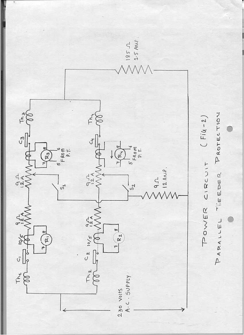
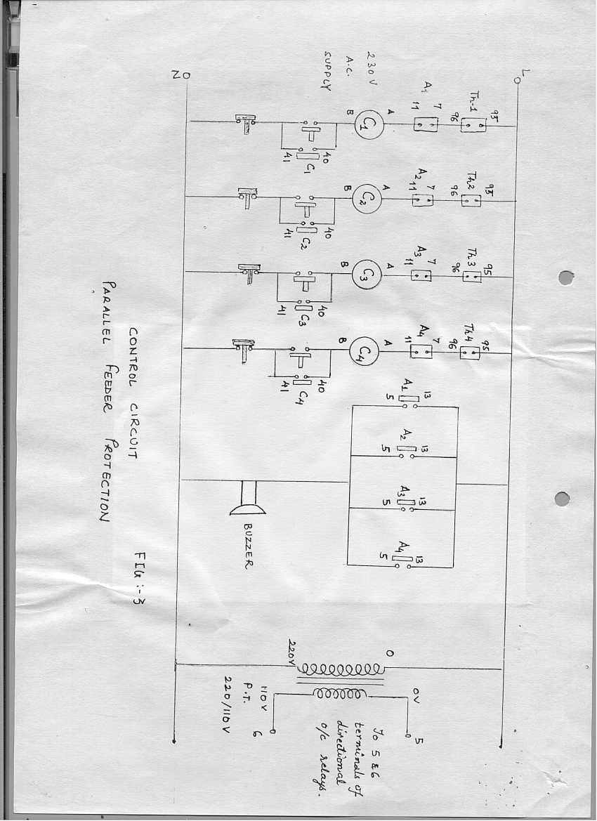
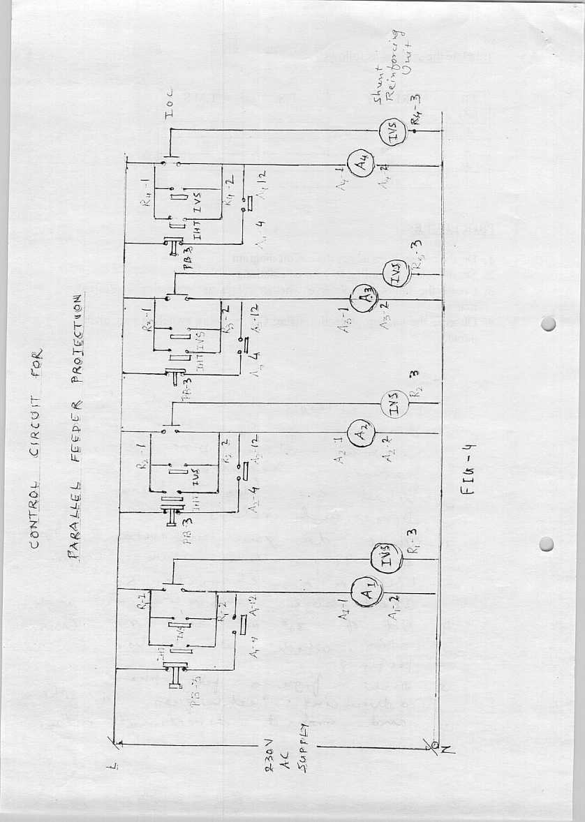
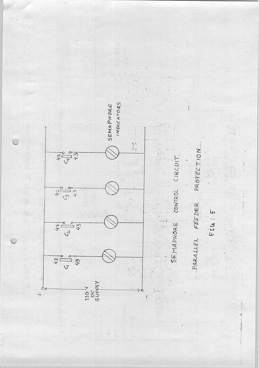
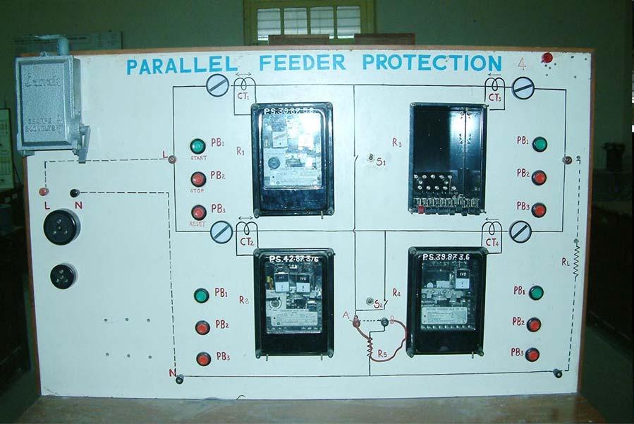
15 L aboratory Simulations: Referring fig. 2, a model for parallel feeders fed from one end is self explanatory. This is a single-phase version of the parallel feeders. One feeder is simulated by two 9 Ω, 12 A rheostats in series. Load is simulated using a 185 Ω, 1.1 A rheostat. Faults are simulated using switches S 1 and S 2 and a limiting resistance of 9Ω, 12 A is used to limit the fault current. The control circuit is similar to that in the radial feeder simulation (Refer to fig. 3, 4 and 5) except for the additional PT to feed directional overcurrent relay. Remote backup can be seen by closing a CT secondary shorting switch at the rear of the panel (thus, making the corresponding relay non-operational). O bservations and Calculations: Calculate the Plug Setting P.S (or Tap Value T.V.) and T.M.S. of relays theoretically such that if one line trips the other healthy line should be able to feed the full power till the load is shed. Remember relay R 1 should provide backup to R 4 and R 2 to R 3. Select some arbitrary T.M.S. for R 3 and R 4 and find the T.M.S. of R 1 and R 2 by keeping proper discrimination time arrival. Tabulate the settings as follows: SR NO Relay P.S. T.M.S. 1 R 1 2 R 2 3 R 3 4 R 4 Procedure: 1. Do the connections as per the circuit diagram. 2. Set the relays according to your calculations Create the faults and observe whether relays are operating in desired manner. 3. Observe the backup protection using C.T. shorting switch at rear of the panel. Q uestions: 1. Draw at least three single line diagrams of power system network where Directional feature is required. 2. What are the problems of Directional relays. 3. What do you understand by Zero Torque Line, Maximum Torque Line, MTA characteristic, Dead Zone, Characteristic Angle? 4. Out of 30 0, 60 0 and 90 0 connection, which would you prefer? 5. Draw figures for phase advancing techniques in phase and ground directional relays. 2
16
17
18
19
20
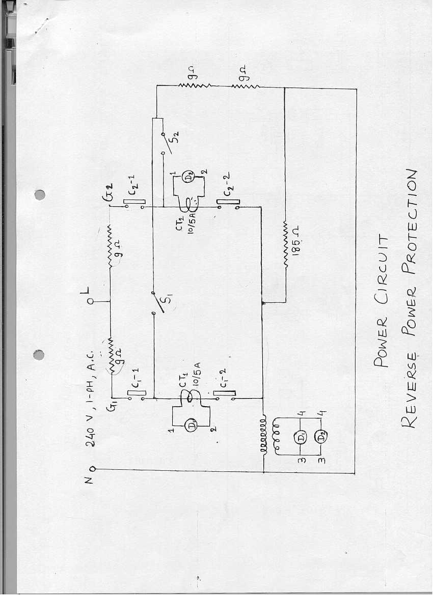
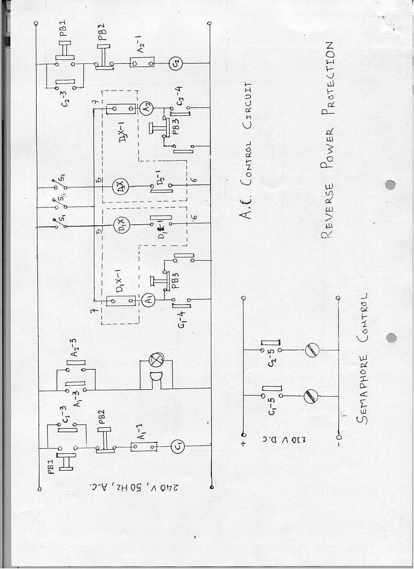
21 EXPERIMENT NO.3 Principle of Reverse Power Protection: Motivation: Reversal of power takes place when turbine does not get steam or water (in thermal/hydro plants). When alternator is connected to infinite bus and its turbine fails, machine works as synchronous motor driving the turbine as a pump; thus direction of current reverses. This experiment is designed to understand and demonstrate all possible conditions of prime-mover failure. Theoretical Background: When prime mover fails (steam input to turbine gets lost), generator works as a synchronous motor driving the turbine as the pump but obviously drawing a very small current w.r.t. its rated value. This condition is not dangerous for the alternator. The damage occurs to the prime mover. In modern power plants there are low forward power relays rather than reverse power relays. This protection is very important as not only it protects the prime mover, but also all class-b protections are routed through this protection (low forward power protection). Experimental Model: The main circuit is shown in fig. 1. The normal operating condition is achieved by keeping the switches S 1 and S 2 open. In this case, there are two parallel paths, each with 9 Ω resistance feeding a load simulated by a 185 Ω rheostat. The two paths model two 240V generators in parallel feeding a load of 185 Ω. The generator currents are measured through CT 1 and CT 2 and fed to relays D 1 and D 2 respectively. D 1 and D 2 are reverse power relays (in fact, low forward power relays to be precise), and hence are also provided with a voltage input through a Voltage Transformer (VT) shown in fig. 1. It is important to note here that D 1 and D 2 remain energized during normal condition. Closing of switch S 1 will make the current through CT 1 equal zero. Closing of S 2 will make the current through CT 2 equal zero. Either of these conditions simulates primemover failure and relay will de-energize in response. S 1 and S 2 are Double Pole Double Throw (DPDT) switches used simultaneously in the main (fig. 1) and control (fig. 2) circuits. The control circuit is shown in fig. 2. It shows that the contactors can be energized by push buttons PB1 and de-energized by PB2, same as for other experiments. The switch S 3 simulates the steam valve interlock. This interlock does not allow the generator to start if the steam valve feeding steam to the turbine is closed. S 3 should be kept open to bypass the lock, i.e., to let contactors close. Procedure: 1. Connect the required circuit. Keep S 3 open. This means A 1 and A 2 can never energize. So, A 1-1 and A 2-1 are always closed. The steam valve interlock is bypassed. 2. Make the contactors ON with pushbuttons. Circuit will energize and relays D 1 and D 2 will operate. Now close S 3. This means that in the control circuit of fig. 2, D 1-1 and D 2-1 will close energizing D 1 X/D 2 X. Hence contacts D 1 X-1 or D 2 X-1 will open out, not allowing auxiliary relays A 1 and A 2 to operate. Thus, contactors remain ON. 1

22 3. Now to simulate prime-mover failure, make switch S 1 on. Relay D 1 will de-energize, hence D 1 X, deenrgizes. D 1 x-1 will close and the auxiliary relay A 1 will operate. A 1-1 will isolate the faulty turbo alternator from bus. Buzzer, bulb and semaphore indicators operate the same way as for other experiments. 4. Open S 1. Then open S3. Now make contactor C 1 On with push button. 5. Close S 2 to simulate zero power in alternator-2. On similar lines to what is explained in steps 1-3, contactor C 2 will open. 6. Draw your own conclusion. 2
23 3
24
25
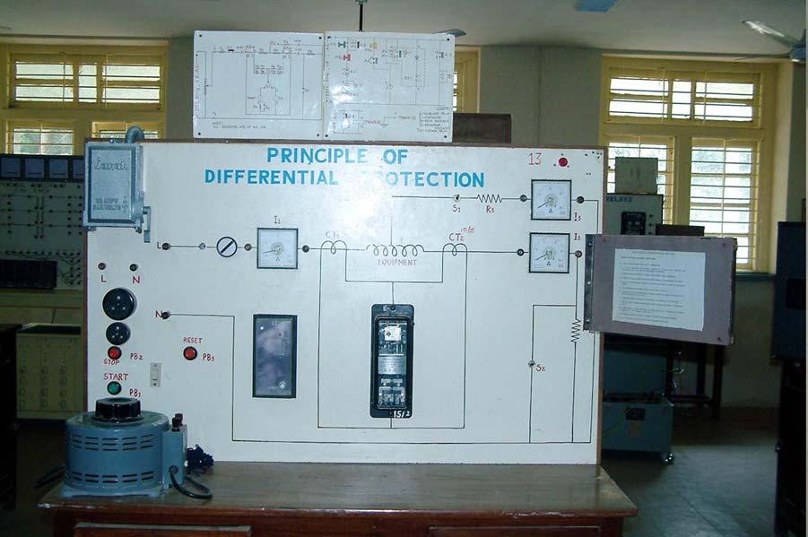
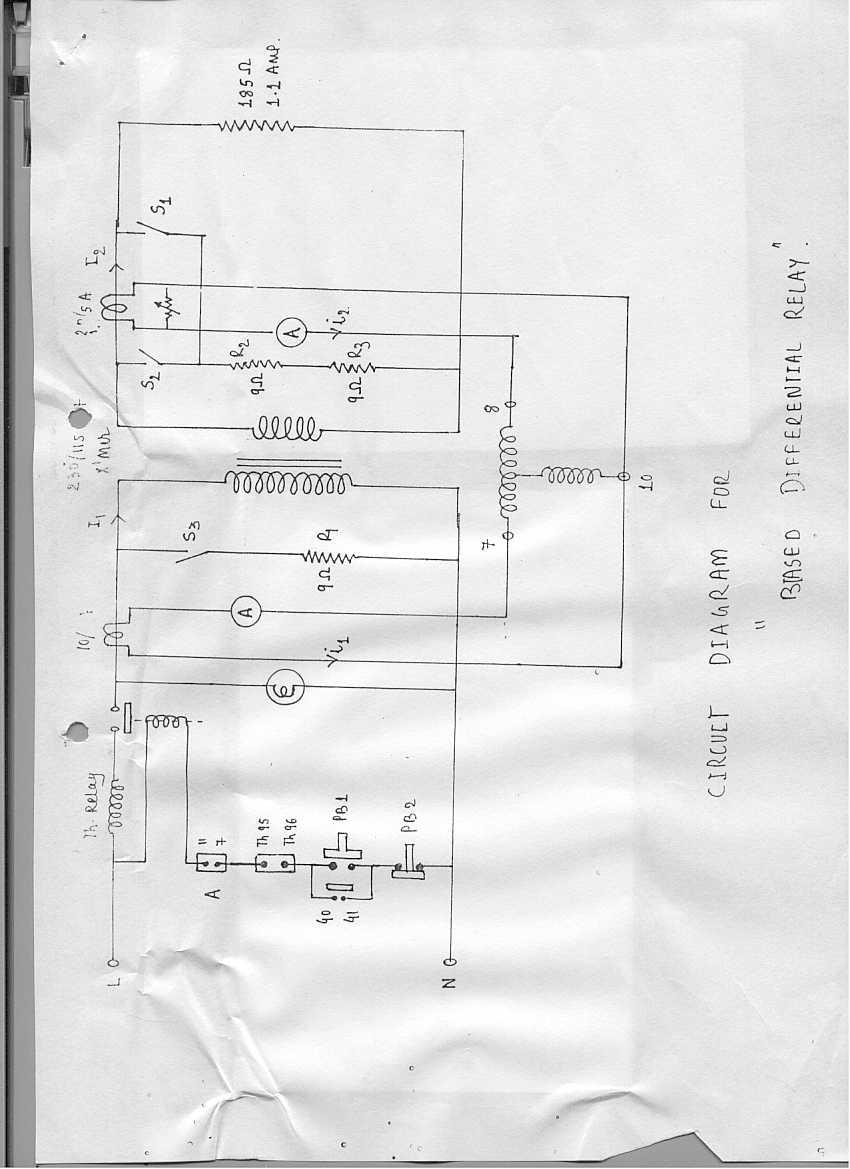
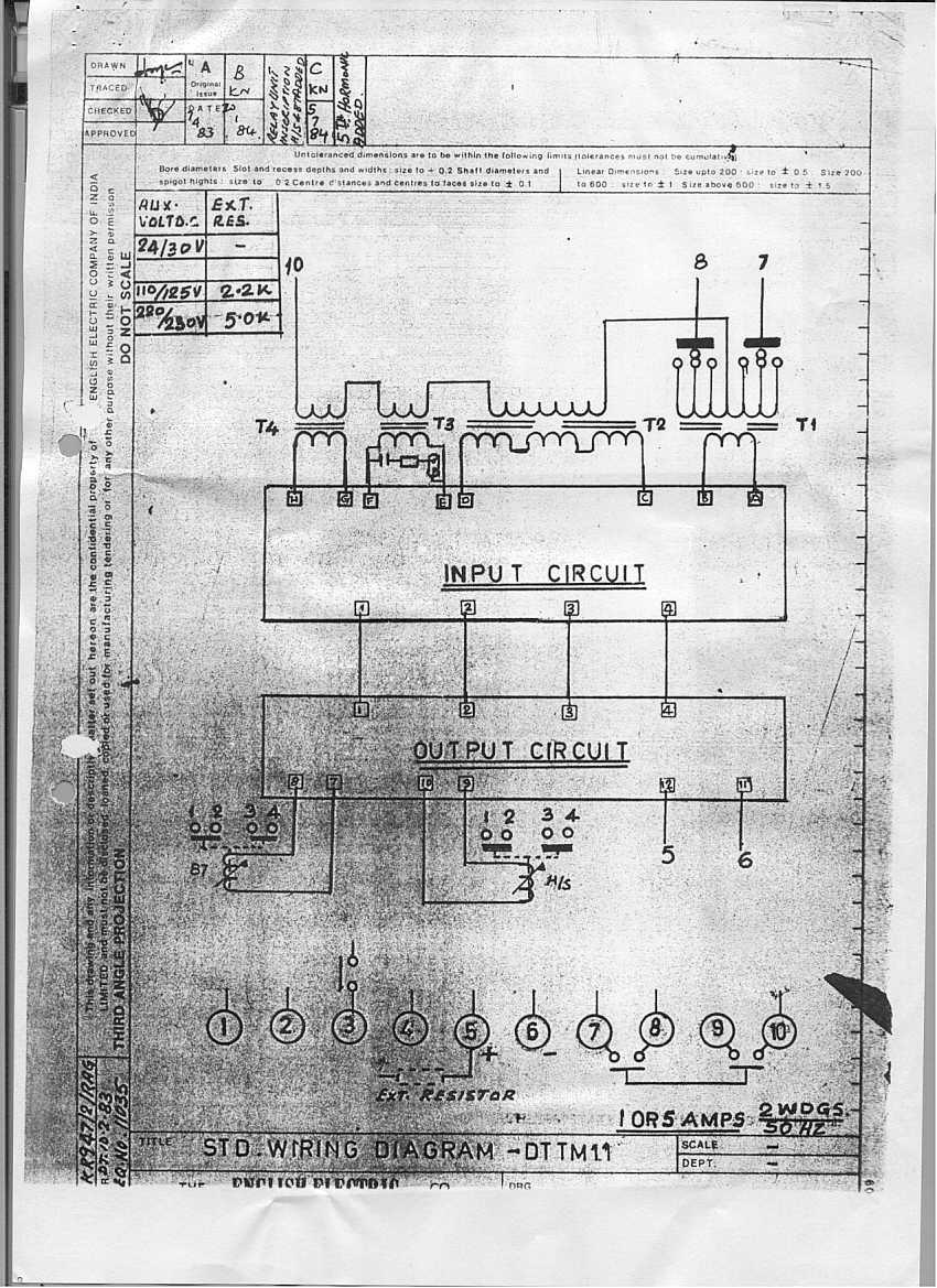
26 EXPERIMENT NO: 4 DIFFERENTIAL PROTECTION OF TRANSFORMER Theoretical Background: The transformer is one of the most important devices and a very expensive equipment of a power system. The internal fault current due to short-circuit of winding within a transformer results in enormous damage to the winding and the core. Hence we use the most reliable, fast and the selective protective scheme, the differential protection scheme, which operates only for the internal faults. Some problems envisaged with differential protection scheme of transformer are listed below with their remedies: 1. The voltage ratings of both sides of transformer are different; hence the CTs used are not identical. So there may be some spill current flowing through the relay that may cause mal-operation. Remedy: Use biased differential relay. 2. The full load current of transformer primary and secondary are different. CT should be selected such that the pilot wire current is the same on both sides otherwise maloperation of relay would occur. To achieve this, the CT ratios required on primary and secondary side are different from the standard ratio. Remedy: CTs of standard ratios are employed in conjunction with interposing CTs. 3. At no load, the transformer secondary current is zero but the magnetizing current flows in the primary. Hence mal-operation of relay may occur due to the presence of spill current. Remedy: As the magnetizing current is only 1-2% of the rated current the basic setting of relay is done such that it does not operate at no-load. 4. During heavy external faults, CT ratio error will result in significant spill current flowing through the operating coil of the relay. Hence the relay can mal-operate. Remedy: Use biased differential relay The power transformers are always provided with a tap-changing arrangement to regulate output voltage as demanded by the load. But CTs are chosen with respect to the normal tap. Hence, tap changing results in a spill current through the relay causing mal-operation. Remedy: Use biased differential relay. 6. When the transformer is switched on there is a large magnetizing inrush which depends on the instant of switching. This current is 8-10 times the normal rated current. Hence relay will mal-operate and will not allow the switching of transformer. Remedy: Use of DTIM-11 relay, or any comparable relay that provides second harmonic restraint. 7. The modern transformers are designed to operate near the knee point voltage of the B-H curve of their core. Hence 20% voltage rise would cause the rise in magnetizing current by 400%. This may cause mal-operation of relay. As the wave shape of the magnetizing current under this condition is rich of 5 th harmonic, the 5 th harmonic bypass circuit of the relay avoids the mal-operation. 1
27 In early days, a time delay was used to deal with the magnetizing inrush. This compromised relay performance when the transformer energizes with a fault already present in the system. The present remedies are: 1. Even harmonic cancellation. 2. Harmonic restraint. 3. Harmonic blocking. 4. De-biasing. Laboratory Simulation Fig. 1 shows the main circuit for demonstrating the biased differential protection. The function of PB1, PB2 and PB3 is to start, stop and to reset the circuit respectively. The switches S1, S2, and S3 are provided to make the fault at different locations. S1 is for an external fault, S2 is for an internal fault, and S3 is for a severe internal fault. The transformer has primary taps for 230V, V, 115 V, 53.3 V and secondary taps for 110 V, V, 55 V and 25.5 V. Procedure: PART-A Application of DTTM-11 for protection of single phase transformer 1. From the rating of the transformer (230/115 V, 1 kva), the CT ratings (10/5 A on primary, 20/5A on secondary), calculate the basic and bias settings of the relay, as well as the setting of the high-set unit. 2. Set the DTTM-11 relay according to calculations. Connect the circuit as shown. 3. Keep the secondary circuit open-circuited. Push PB1 button to energize the transformer with no load. Observe that the transformer can be energized without the relay operating. Repeat this process several times and observe the relay never operates while energizing the transformer. This is because DTTM-11 has the second harmonic restraint feature. This obviates the necessity of time delay during starting. 4. After switching the circuit off, complete the secondary circuit and make the circuit ON. Observe that relay does not operate for normal condition. 5. Make S1 ON, and observe that the relay does not operate for external faults as proved in the calculations. Switch S1 OFF. 6. Energize the circuit. Make S2 ON (internal fault on secondary side), and observe that relay 87 operates as proved in the calculations. Switch S2 OFF. 7. Energize the circuit. Make S3 ON (internal severe fault) and observe that unit 87 and the high set unit both operate as proved in the calculations. Switch S3 OFF. 8. Introduce a variable resistance across the secondary of CT on the secondary as shown in fig. 1. This simulates CT saturation or CT mismatch. Energize the circuit. Create an external fault using S1. Observe if the relay mal-operates. Decrease the CT secondary resistance till the relay mal-operates. Now switch off the supply, increase the bias setting and switch on the circuit again. Observe that for the same external fault, the relay does not operate. PART-B Effect of tap-changing and effect of inrush current: 1. Shift the transformer to another table that has similar set-up but has ABB-make type T relay. This relay does not have second harmonic restraint capability. Set this relay 2

28 with the same settings as for DTTM-11 relay. However, simulate the load resistance with an 18 Ω rheostat. 2. Repeat step 3 of part-a above. Observe that the relay mal-operates several times. The intensity of inrush depends on the instantaneous value of the input voltage when the transformer is energized, hence the relay does not mal-operate all the times. Now repeat the same process with increased time delay setting (this setting is provided with this relay). Observe the mal-operation ceases. However, this remedy is dangerous if the transformer is energized with an existing fault, especially in a part of system that has high fault levels. Keep the time delay in effect for the rest of the experiment. 3. Switch off the circuit and connect the secondary circuit. Switch on the transformer and observe the relay not operating for normal operation. 4. Change the primary tap to V and repeat step-3. Observe the relay mal-operates. 5. Increase the bias setting and switch on the circuit. Observe that the relay does not operate. 3
29 4
30 5
31
32
A NEW DIRECTIONAL OVER CURRENT RELAYING SCHEME FOR DISTRIBUTION FEEDERS IN THE PRESENCE OF DG
 A NEW DIRECTIONAL OVER CURRENT RELAYING SCHEME FOR DISTRIBUTION FEEDERS IN THE PRESENCE OF DG CHAPTER 3 3.1 INTRODUCTION In plain radial feeders, the non-directional relays are used as they operate when
Electrical Protection System Design and Operation
 ELEC9713 Industrial and Commercial Power Systems Electrical Protection System Design and Operation 1. Function of Electrical Protection Systems The three primary aims of overcurrent electrical protection
Busbars and lines are important elements
 CHAPTER CHAPTER 23 Protection of Busbars and Lines 23.1 Busbar Protection 23.2 Protection of Lines 23.3 Time-Graded Overcurrent Protection 23.4 Differential Pilot-Wire Protection 23.5 Distance Protection
Transformer protection IED RET 670
 Gunnar Stranne Transformer protection IED RET 670 Santiago Septiembre 5, 2006 1 Transformer protection IED RET670 2 Introduction features and applications Differential protection functions Restricted Earth
Transformer Fault Categories
 Transformer Fault Categories 1. Winding and terminal faults 2. Sustained or uncleared external faults 3. Abnormal operating conditions such as overload, overvoltage and overfluxing 4. Core faults 1 (1)
Transmission Lines and Feeders Protection Pilot wire differential relays (Device 87L) Distance protection
 Distance protection") Transmission Lines and Feeders Protection Pilot wire differential relays (Device 87L) Distance protection 133 1. Pilot wire differential relays (Device 87L) The pilot wire differential relay is a high-speed
Transmission Lines and Feeders Protection Pilot wire differential relays (Device 87L) Distance protection 133 1. Pilot wire differential relays (Device 87L) The pilot wire differential relay is a high-speed
Transformer Protection
 Transformer Protection Transformer Protection Outline Fuses Protection Example Overcurrent Protection Differential Relaying Current Matching Phase Shift Compensation Tap Changing Under Load Magnetizing
DESIGN ANALYSIS AND REALIZATION OF MICROCONTROLLER BASED OVER CURRENT RELAY WITH IDMT CHARACTERISTICS: A PROTEUS SIMULATION
 DESIGN ANALYSIS AND REALIZATION OF MICROCONTROLLER BASED OVER CURRENT RELAY WITH IDMT CHARACTERISTICS: A PROTEUS SIMULATION HARSH DHIMAN Department of Electrical Engineering, The M. S. University, Vadodara,
Power System Protection Part VII Dr.Prof.Mohammed Tawfeeq Al-Zuhairi. Differential Protection (Unit protection)
") Differential Protection (Unit protection) Differential Protection Differential protection is the best technique in protection. In this type of protection the electrical quantities entering and leaving
Differential Protection (Unit protection) Differential Protection Differential protection is the best technique in protection. In this type of protection the electrical quantities entering and leaving
Generator in a power station requires different type of
 Laboratory Simulation of Generator Protection Rashesh P. Mehta, Member, IEEE, Bhuvanesh Oza, Member, IEEE Abstract Generator is the most important and costly equipment in the power system. For the reliability
Unit Protection Differential Relays
 Unit Protection PROF. SHAHRAM MONTASER KOUHSARI Current, pu Current, pu Protection Relays - BASICS Note on CT polarity dots Through-current: must not operate Internal fault: must operate The CT currents
www. ElectricalPartManuals. com Transformer Differential Relay MD32T Transformer Differential Relay
 Transformer Differential Relay The MD3T Transformer Differential Relay is a member of Cooper Power Systems Edison line of microprocessor based protective relays. The MD3T relay offers the following functions:
RAIDK, RAIDG, RAPDK and RACIK Phase overcurrent and earth-fault protection assemblies based on single phase measuring elements
 RAIDK, RAIDG, RAPDK and RACIK Phase overcurrent and earth-fault protection assemblies based on single phase measuring elements User s Guide General Most faults in power systems can be detected by applying
Numbering System for Protective Devices, Control and Indication Devices for Power Systems
 Appendix C Numbering System for Protective Devices, Control and Indication Devices for Power Systems C.1 APPLICATION OF PROTECTIVE RELAYS, CONTROL AND ALARM DEVICES FOR POWER SYSTEM CIRCUITS The requirements
9 Overcurrent Protection for Phase and Earth Faults
 Overcurrent Protection for Phase and Earth Faults Introduction 9. Co-ordination procedure 9.2 Principles of time/current grading 9.3 Standard I.D.M.T. overcurrent relays 9.4 Combined I.D.M.T. and high
Power systems Protection course
 Al-Balqa Applied University Power systems Protection course Department of Electrical Energy Engineering 1 Part 5 Relays 2 3 Relay Is a device which receive a signal from the power system thought CT and
PJM Manual 07:: PJM Protection Standards Revision: 2 Effective Date: July 1, 2016
 PJM Manual 07:: PJM Protection Standards Revision: 2 Effective Date: July 1, 2016 Prepared by System Planning Division Transmission Planning Department PJM 2016 Table of Contents Table of Contents Approval...6
PROTECTION of electricity distribution networks
 PROTECTION of electricity distribution networks Juan M. Gers and Edward J. Holmes The Institution of Electrical Engineers Contents Preface and acknowledgments x 1 Introduction 1 1.1 Basic principles of
 Power Station Electrical Protection A 2 B 2 C 2 Neutral C.T E M L } a 2 b 2 c 2 M M M CT Restricted E/F Relay L L L TO TRIP CIRCUIT Contents 1 The Need for Protection 2 1.1 Types of Faults............................
CHAPTER 3 REVIEW OF POWER TRANSFORMER PROTECTION SCHEMES
 CHAPTER 3 REVIEW OF POWER TRANSFORMER PROTECTION SCHEMES 3.1. Introduction Power Transformer is the nerve centre of any power distribution system. The capacity of power transformers is generally decided
PIPSPC. Prepared by Eng: Ahmed Safie Eldin. And. Introduction. Protection Control. Practical. System. Power
 PIPSPC Practical Introduction Power System Protection Control Practical Introduction To Power System Protection And Control Prepared by Eng: Ahmed Safie Eldin 2005 Contents POWER SYSTEMS PRINCIPALS. 1
POWER SYSTEM II LAB MANUAL
 POWER SYSTEM II LAB MANUAL (CODE : EE 692) JIS COLLEGE OF ENGINEERING (An Autonomous Institution) Electrical Engineering Department Kalyani, Nadia POWER SYSTEM II CODE : EE 692 Contacts :3P Credits : 2
Protection Basics Presented by John S. Levine, P.E. Levine Lectronics and Lectric, Inc GE Consumer & Industrial Multilin
 Protection Basics Presented by John S. Levine, P.E. Levine Lectronics and Lectric, Inc. 770 565-1556 John@L-3.com 1 Protection Fundamentals By John Levine 2 Introductions Tools Outline Enervista Launchpad
BUS2000 Busbar Differential Protection System
 BUS2000 Busbar Differential Protection System Differential overcurrent system with percentage restraint protection 1 Typical Busbar Arrangements Single Busbar Double Busbar with Coupler Breaker and a Half
POWER SYSTEM ANALYSIS TADP 641 SETTING OF OVERCURRENT RELAYS
 POWER SYSTEM ANALYSIS TADP 641 SETTING OF OVERCURRENT RELAYS Juan Manuel Gers, PhD Protection coordination principles Relay coordination is the process of selecting settings that will assure that the relays
Protection of Electrical Networks. Christophe Prévé
 Protection of Electrical Networks Christophe Prévé This Page Intentionally Left Blank Protection of Electrical Networks This Page Intentionally Left Blank Protection of Electrical Networks Christophe Prévé
This webinar brought to you by The Relion Product Family Next Generation Protection and Control IEDs from ABB
 This webinar brought to you by The Relion Product Family Next Generation Protection and Control IEDs from ABB Relion. Thinking beyond the box. Designed to seamlessly consolidate functions, Relion relays
EASUN REYROLLE LIMITED
 OCTOBER 2003 APPLICATION AND COMMISSIONING MANUAL FOR NUMERICAL BIASED DIFFERENTIAL PROTECTION RELAY TYPE - MIB202 EASUN REYROLLE LIMITED 1 ISSUE NO : 1 st Issue DATE OF ISSUE : 01-10 - 2003 DEPARTMENT
Course No: 1 13 (3 Days) FAULT CURRENT CALCULATION & RELAY SETTING & RELAY CO-ORDINATION. Course Content
 FAULT CURRENT CALCULATION & RELAY SETTING & RELAY CO-ORDINATION. Course Content") Course No: 1 13 (3 Days) FAULT CURRENT CALCULATION & RELAY SETTING & RELAY CO-ORDINATION Sr. No. Course Content 1.0 Fault Current Calculations 1.1 Introduction to per unit and percentage impedance 1.2
Course No: 1 13 (3 Days) FAULT CURRENT CALCULATION & RELAY SETTING & RELAY CO-ORDINATION Sr. No. Course Content 1.0 Fault Current Calculations 1.1 Introduction to per unit and percentage impedance 1.2
www. ElectricalPartManuals. com Generator Differential Relay MD32G Rotating Machine Differential Relay
 Generator Differential Relay The MD3G Rotating Machine Differential Relay is a member of Cooper Power Systems Edison line of microprocessor based protective relays. The MD3G relay offers the following
EARTH FAULT PROTECTION VIS-A-VIS GENERATOR GROUNDING SYSTEM
 EARTH FAULT PROTECTION VIS-A-VIS GENERATOR GROUNDING SYSTEM BY MR. H. C. MEHTA AT 1 ST INDIA DOBLE PROTECTION AND AUTOMATION CONFERENCE, NOV 2008 POWER-LINKER Wisdom is not Virtue but Necessity hcmehta@powerlinker.org
R10. IV B.Tech I Semester Regular/Supplementary Examinations, Nov/Dec SWITCH GEAR AND PROTECTION. (Electrical and Electronics Engineering)
") R10 Set No. 1 Code No: R41023 1. a) Explain how arc is initiated and sustained in a circuit breaker when the CB controls separates. b) The following data refers to a 3-phase, 50 Hz generator: emf between
R10 Set No. 1 Code No: R41023 1. a) Explain how arc is initiated and sustained in a circuit breaker when the CB controls separates. b) The following data refers to a 3-phase, 50 Hz generator: emf between
Differential Protection with REF 542plus Feeder Terminal
 Differential Protection with REF 542plus Application and Setting Guide kansikuva_bw 1MRS 756281 Issued: 09.01.2007 Version: A Differential Protection with REF 542plus Application and Setting Guide Contents:
Overcurrent relays coordination using MATLAB model
 JEMT 6 (2018) 8-15 ISSN 2053-3535 Overcurrent relays coordination using MATLAB model A. Akhikpemelo 1 *, M. J. E. Evbogbai 2 and M. S. Okundamiya 3 1 Department of Electrical and Electronic Engineering,
Transformer Protection
 Transformer Protection Nature of transformer faults TXs, being static, totally enclosed and oil immersed develop faults only rarely but consequences large. Three main classes of faults. 1) Faults in Auxiliary
N. TEST TEST DESCRIPTION
 Multi function system for testing substation equipment such as: current, voltage and power transformers, all type of protection relays, energy meters and transducers Primary injection testing capabilities
System Protection and Control Subcommittee
 Power Plant and Transmission System Protection Coordination Reverse Power (32), Negative Sequence Current (46), Inadvertent Energizing (50/27), Stator Ground Fault (59GN/27TH), Generator Differential (87G),
DIGITAL EARTH FAULT RELAY
 DIGITAL IDMT / DEFINITE TIME / INSTANTANEOUS Features ŸCompact ŸIDMT (4 IEC curves), Definite Time & Instantaneous ŸWide setting ranges ŸFully digital acquisition & processing of data ŸWide operating voltages
Types CDG 11 and CDG 16 Inverse Time Overcurrent and Earth Fault Relay
 Types CDG 11 and CDG 16 Inverse Time Overcurrent and Earth Fault Relay Types CDG 11 and CDG 16 Inverse Time Overcurrent and Earth Fault Relay Relay withdrawn from case Application The type CDG 11 relay
Impact of transient saturation of Current Transformer during cyclic operations Analysis and Diagnosis
 1 Impact of transient saturation of Current Transformer during cyclic operations Analysis and Diagnosis BK Pandey, DGM(OS-Elect) Venkateswara Rao Bitra, Manager (EMD Simhadri) 1.0 Introduction: Current
Earth Fault Relay EFSPL-1A/5A
 Earth Fault Relay EFSPL-1A/5A IEEE DEVICES CODE-50N Features Static Device Compact, Reliable with Aesthetic Value Rugged, Robust and Tropicalised design Consistent repeat accuracy Wide Current Operating
Earth Fault Protection
 Earth Fault Protection Course No: E03-038 Credit: 3 PDH Velimir Lackovic, Char. Eng. Continuing Education and Development, Inc. 9 Greyridge Farm Court Stony Point, NY 10980 P: (877) 322-5800 F: (877) 322-4774
A Tutorial on the Application and Setting of Collector Feeder Overcurrent Relays at Wind Electric Plants
 A Tutorial on the Application and Setting of Collector Feeder Overcurrent Relays at Wind Electric Plants Martin Best and Stephanie Mercer, UC Synergetic, LLC Abstract Wind generating plants employ several
Data. Dr Murari Mohan Saha ABB AB. KTH/EH2740 Lecture 3. Data Acquisition Block. Logic. Measurement. S/H and A/D Converter. signal conditioner
 Digital Protective Relay Dr Murari Mohan Saha ABB AB KTH/EH2740 Lecture 3 Introduction to Modern Power System Protection A digital protective relay is an industrial microprocessor system operating in real
Sequence Networks p. 26 Sequence Network Connections and Voltages p. 27 Network Connections for Fault and General Unbalances p. 28 Sequence Network
 Preface p. iii Introduction and General Philosophies p. 1 Introduction p. 1 Classification of Relays p. 1 Analog/Digital/Numerical p. 2 Protective Relaying Systems and Their Design p. 2 Design Criteria
Shortcomings of the Low impedance Restricted Earth Fault function as applied to an Auto Transformer. Anura Perera, Paul Keller
 Shortcomings of the Low impedance Restricted Earth Fault function as applied to an Auto Transformer Anura Perera, Paul Keller System Operator - Eskom Transmission Introduction During the design phase of
Stabilized Differential Relay SPAD 346. Product Guide
 Issued: July 1998 Status: Updated Version: D/21.03.2006 Data subject to change without notice Features Integrated three-phase differential relay, three-phase overcurrent relay and multiconfigurable earth-fault
1 INTRODUCTION 1.1 PRODUCT DESCRIPTION
 GEK-00682D INTRODUCTION INTRODUCTION. PRODUCT DESCRIPTION The MDP Digital Time Overcurrent Relay is a digital, microprocessor based, nondirectional overcurrent relay that protects against phase-to-phase
Protective Relays Digitrip 3000
 New Information Technical Data Effective: May 1999 Page 1 Applications Provides reliable 3-phase and ground overcurrent protection for all voltage levels. Primary feeder circuit protection Primary transformer
PRC Generator Relay Loadability. Guidelines and Technical Basis Draft 5: (August 2, 2013) Page 1 of 76
 Page 1 of 76") PRC-025-1 Introduction The document, Power Plant and Transmission System Protection Coordination, published by the NERC System Protection and Control Subcommittee (SPCS) provides extensive general discussion
PRC-025-1 Introduction The document, Power Plant and Transmission System Protection Coordination, published by the NERC System Protection and Control Subcommittee (SPCS) provides extensive general discussion
ELECTRICIAN S THEORY EXAMINATION 17 November 2012 QUESTION AND ANSWER BOOKLET
 Candidate Code No. ET43 For Board Use Only Result Date Int Result Date Int ELECTRICIAN S THEORY EXAMINATION 17 November 2012 QUESTION AND ANSWER BOOKLET INSTRUCTIONS READ CAREFULLY Time Allowed: Three
Distribution/Substation Transformer
 Distribution/Substation Transformer Type VFI, Vacuum Fault Interrupter Transformer Option Functional Specification Guide Functional specification for 15 kv, 25 kv, or 35 kv vacuum fault interrupter distribution/substation
Application and Commissioning Manual for Numerical Over Current Protection Relays Type MIT 121/131 CONTENTS PAGE APPLICATION 2-4 INSTALLATION 5-11
 Application and Commissioning Manual for Numerical Over Current Protection Relays Type MIT 121/131 CONTENTS PAGE APPLICATION 2-4 INSTALLATION 5-11 COMMISSIONING 12-16 DRAWINGS 17-18 1 1. INTRODUCTION APPLICATION
PRC Generator Relay Loadability. Guidelines and Technical Basis Draft 4: (June 10, 2013) Page 1 of 75
 Page 1 of 75") PRC-025-1 Introduction The document, Power Plant and Transmission System Protection Coordination, published by the NERC System Protection and Control Subcommittee (SPCS) provides extensive general discussion
PRC-025-1 Introduction The document, Power Plant and Transmission System Protection Coordination, published by the NERC System Protection and Control Subcommittee (SPCS) provides extensive general discussion
DEPARTMENT OF ELECTRICAL ENGINEERING BENGAL ENGINEERING AND SCIENCE UNIVERSITY, SHIBPUR
 DEPARTMENT OF ELECTRICAL ENGINEERING BENGAL ENGINEERING AND SCIENCE UNIVERSITY, SHIBPUR Power system protection Laboratory (EE 852) 8 th Semester Electrical Expt. No. 852/1 BIFFI S METHOD FOR TESTING CURRENT
DIGITAL EARTH FAULT RELAY
 DIGITAL IDMT / DEFINITE TIME / INSTANTANEOUS Features Compact IDMT (4 IEC curves), Definite Time & Instantaneous Wide setting ranges Fully digital acquisition & processing of data Wide operating voltages
POWER SYSTEM PRINCIPLES APPLIED IN PROTECTION PRACTICE. Professor Akhtar Kalam Victoria University
 POWER SYSTEM PRINCIPLES APPLIED IN PROTECTION PRACTICE Professor Akhtar Kalam Victoria University The Problem Calculate & sketch the ZPS, NPS & PPS impedance networks. Calculate feeder faults. Calculate
Bus Protection Fundamentals
 Bus Protection Fundamentals Terrence Smith GE Grid Solutions 2017 Texas A&M Protective Relay Conference Bus Protection Requirements High bus fault currents due to large number of circuits connected: CT
Solution for Effect of Zero Sequence Currents on Y-Y Transformer Differential Protection
 ABSTRACT National conference on Engineering Innovations and Solutions (NCEIS 2018) International Journal of Scientific Research in Computer Science, Engineering and Information Technology 2018 IJSRCSEIT
7PG21 Solkor Rf Feeder Protection Energy Management
 Reyrolle Protection Devices 7PG21 Solkor Rf Feeder Protection Energy Management 7PG21 Solkor Rf Contents Contents Technical Manual Chapters 1. Description of Operation 2. Performance Specification 3.
Transmission System Phase Backup Protection
 Reliability Guideline Transmission System Phase Backup Protection NERC System Protection and Control Subcommittee Draft for Planning Committee Approval June 2011 Table of Contents 1. Introduction and Need
PSV3St _ Phase-Sequence Voltage Protection Stage1 (PSV3St1) Stage2 (PSV3St2)
 Stage2 (PSV3St2)") 1MRS752324-MUM Issued: 3/2000 Version: D/23.06.2005 Data subject to change without notice PSV3St _ Phase-Sequence Voltage Protection Stage1 (PSV3St1) Stage2 (PSV3St2) Contents 1. Introduction... 2 1.1
1MRS752324-MUM Issued: 3/2000 Version: D/23.06.2005 Data subject to change without notice PSV3St _ Phase-Sequence Voltage Protection Stage1 (PSV3St1) Stage2 (PSV3St2) Contents 1. Introduction... 2 1.1
NERC Protection Coordination Webinar Series June 9, Phil Tatro Jon Gardell
 Power Plant and Transmission System Protection Coordination GSU Phase Overcurrent (51T), GSU Ground Overcurrent (51TG), and Breaker Failure (50BF) Protection NERC Protection Coordination Webinar Series
Application of Low-Impedance 7SS601 Busbar Differential Protection
 Application of Low-Impedance 7SS601 Busbar Differential Protection 1. Introduction Utilities have to supply power to their customers with highest reliability and minimum down time. System disturbances,
Current Transformer Requirements for VA TECH Reyrolle ACP Relays. PREPARED BY:- A Allen... APPROVED :- B Watson...
 TECHNICAL REPORT APPLICATION GUIDE TITLE: Current Transformer Requirements for VA TECH Reyrolle ACP Relays PREPARED BY:- A Allen... APPROVED :- B Watson... REPORT NO:- 990/TIR/005/02 DATE :- 24 Jan 2000
ELECTRICAL POWER ENGINEERING
 Introduction This trainer has been designed to provide students with a fully comprehensive knowledge in Electrical Power Engineering systems. The trainer is composed of a set of modules for the simulation
POWER SYSTEMSLAB YEAR SEM EEE. Dr. J. Sridevi
 POWER SYSTEMSLAB YEAR SEM EEE By Dr. J. Sridevi Gokaraju Rangaraju Institute of Engineering & Technology Bachupally 1 GOKARAJU RANGARAJU INSTITUTE OF ENGINEERING AND TECHNOLOGY (Autonomous) Bachupally,
SPAD 346 C Stabilized differential relay
 SPAD 346 C Stabilized differential relay Stabilized Differential Relay Type SPAD 346 C Features Integrated three-phase differential relay, three-phase overcurrent relay and multiconfigurable earth-fault
200ADM-P. Current Injection System with Phase Shift A 3.000s 2.000A 50.00Hz 0.0. Features
 CT ratio Power Harmonics ac+dc 200ADM-P Current Injection System with Phase Shift Features 0-200A output current True RMS metering with 1 cycle capture Variable auxiliary AC voltage/current output with
CDV 22, 62. Voltage Controlled Overcurrent Relay GRID PROTECTION
 PROTECTION CDV 22, 62 Voltage Controlled Overcurrent Relay CDV22 relay is used for overload and fault protection for ac generators when the sustained short circuit current is less than the full load current.
Transmission Protection Overview
 Transmission Protection Overview 2017 Hands-On Relay School Daniel Henriod Schweitzer Engineering Laboratories Pullman, WA Transmission Line Protection Objective General knowledge and familiarity with
ELECTRICAL POWER TRANSMISSION TRAINER
 ELECTRICAL POWER TRANSMISSION TRAINER ELECTRICAL POWER TRANSMISSION TRAINER This training system has been designed to provide the students with a fully comprehensive knowledge in Electrical Power Engineering
OPERATING, METERING AND EQUIPMENT PROTECTION REQUIREMENTS FOR PARALLEL OPERATION OF LARGE-SIZE GENERATING FACILITIES GREATER THAN 25,000 KILOWATTS
 OPERATING, METERING AND EQUIPMENT PROTECTION REQUIREMENTS FOR PARALLEL OPERATION OF LARGE-SIZE GENERATING FACILITIES GREATER THAN 25,000 KILOWATTS AND MEDIUM-SIZE FACILITIES (5,000-25,000KW) CONNECTED
Problems connected with Commissioning of Power Transformers
 Problems connected with Commissioning of Power Transformers ABSTRACT P Ramachandran ABB India Ltd, Vadodara, India While commissioning large Power Transformers, certain abnormal phenomena were noticed.
Bus protection with a differential relay. When there is no fault, the algebraic sum of circuit currents is zero
 Bus protection with a differential relay. When there is no fault, the algebraic sum of circuit currents is zero Consider a bus and its associated circuits consisting of lines or transformers. The algebraic
Reyrolle Protection Devices. 7PG21 Solkor R/Rf Pilot Wire Current Differential Protection. Answers for energy
 Reyrolle Protection Devices 7PG21 Solkor R/Rf Pilot Wire Current Differential Protection Answers for energy 7PG21 Solkor R/Rf Pilot Wire Current Differential Protection Additional Options 15kV Isolation
U I. Time Overcurrent Relays. Basic equation. More or less approximates thermal fuse. » Allow coordination with fuses 9/24/2018 ECE525.
 Time Overcurrent Relays More or less approximates thermal fuse» Allow coordination with fuses Direction of Current nduced Torque Restraining Spring Reset Position Time Dial Setting Disk Basic equation
Burdens & Current Transformer Requirements of MiCOM Relays. Application Notes B&CT/EN AP/B11. www. ElectricalPartManuals. com
 Burdens & Current Transformer Requirements of MiCOM Relays Application Notes B&CT/EN AP/B11 Application Notes B&CT/EN AP/B11 Burdens & CT Req. of MiCOM Relays Page 1/46 CONTENTS 1. ABBREVIATIONS & SYMBOLS
1960 Research Drive, Suite 100, Troy, Michigan with. REVISION: December 10, 2007 (Supersedes previous versions) Prepared by:
 Prepared by:") ENGINEERING SERVICES 1960 Research Drive, Suite 100, Troy, Michigan 48083 ARC FLASH REDUCTION with SEPAM RELAY ZONE SELECTIVE INTERLOCKING REVISION: December 10, 2007 (Supersedes previous versions) Prepared
ENGINEERING SERVICES 1960 Research Drive, Suite 100, Troy, Michigan 48083 ARC FLASH REDUCTION with SEPAM RELAY ZONE SELECTIVE INTERLOCKING REVISION: December 10, 2007 (Supersedes previous versions) Prepared
Switch-on-to-Fault Schemes in the Context of Line Relay Loadability
 Attachment C (Agenda Item 3b) Switch-on-to-Fault Schemes in the Context of Line Relay Loadability North American Electric Reliability Council A Technical Document Prepared by the System Protection and
Appendix S: PROTECTION ALTERNATIVES FOR VARIOUS GENERATOR CONFIGURATIONS
 Appendix S: PROTECTION ALTERNATIVES FOR VARIOUS GENERATOR CONFIGURATIONS S1. Standard Interconnection Methods with Typical Circuit Configuration for Single or Multiple Units Note: The protection requirements
Overcurrent Protective Relays
 Power System Protection Overcurrent Protective Relays Dr.Professor Mohammed Tawfeeq Lazim Alzuhairi 99 Power system protection Dr.Mohammed Tawfeeq Overcurrent Protective Relays Overcurrent relays Overcurrent
Improving Transformer Protection
 Omaha, NB October 12, 2017 Improving Transformer Protection Wayne Hartmann VP, Customer Excellence Senior Member, IEEE Wayne Hartmann Senior VP, Customer Excellence Speaker Bio whartmann@beckwithelectric.com
OPEN-PHASE DETECTION TECHNIQUES FOR CRITICAL STANDBY SUPPLIES
 OPEN-PHASE DETECTION TECHNIQUES FOR CRITICAL STANDBY SUPPLIES U AJMAL, GE Grid Solutions UK Ltd, usman.ajmal@ge.com S SUBRAMANIAN, GE Grid Solutions UK Ltd, sankara.subramanian@ge.com H Ha GE Grid Solutions
International Journal of Advance Engineering and Research Development
 Scientific Journal of Impact Factor (SJIF): 3.134 International Journal of Advance Engineering and Research Development Volume 2,Issue 12,December -2015 E-ISSN (O): 2348-4470 P-ISSN (P): 2348-6406 Detection
Generator Protection GENERATOR CONTROL AND PROTECTION
 Generator Protection Generator Protection Introduction Device Numbers Symmetrical Components Fault Current Behavior Generator Grounding Stator Phase Fault (87G) Field Ground Fault (64F) Stator Ground Fault
Hamdy Faramawy Senior Application Specialist ABB Sweden
 Design, Engineering and Application of New Firm Capacity Control System (FCCS) Mohammed Y. Tageldin, MSc. MIET Senior Protection Systems Engineer ABB United Kingdom mohammed.tageldin@gb.abb.com Hamdy Faramawy
Transmission Line Protection Objective. General knowledge and familiarity with transmission protection schemes
 Transmission Line Protection Objective General knowledge and familiarity with transmission protection schemes Transmission Line Protection Topics Primary/backup protection Coordination Communication-based
SYNCHRONISING AND VOLTAGE SELECTION
 SYNCHRONISING AND VOLTAGE SELECTION This document is for Relevant Electrical Standards document only. Disclaimer NGG and NGET or their agents, servants or contractors do not accept any liability for any
Testing of Circuit Breaker and over Current Relay Implementation by Using MATLAB / SIMULINK
 Testing of Circuit Breaker and over Current Relay Implementation by Using MATLAB / SIMULINK Dinesh Kumar Singh dsdineshsingh012@gmail.com Abstract Circuit breaker and relays are being utilized for secure,
FINAL - ET 60 - Electrician Theory Examination Marking Schedule
 FINAL - ET 60 - Electrician Theory Examination Marking Schedule Notes:1. means that the preceding statement/answer earns 1 mark. 2. This schedule sets out the accepted answers to the examination questions.
Relion 605 series Self-Powered Feeder Protection REJ603 Product Guide
 Relion 605 series Relion 605 series Self-Powered Feeder Protection Product Guide Contents 1 Description...3 2 Protection functions...3 3 Application...4 4 Self-supervision...4 5 Inputs and outputs...4
NERC Protection Coordination Webinar Series June 16, Phil Tatro Jon Gardell
 Power Plant and Transmission System Protection Coordination Phase Distance (21) and Voltage-Controlled or Voltage-Restrained Overcurrent Protection (51V) NERC Protection Coordination Webinar Series June
Overcurrent and Overload Protection of AC Machines and Power Transformers
 Exercise 2 Overcurrent and Overload Protection of AC Machines and Power Transformers EXERCISE OBJECTIVE When you have completed this exercise, you will understand the relationship between the power rating
Phase and neutral overcurrent protection
 Phase and neutral overcurrent protection Page 1 ssued June 1999 Changed since July 1998 Data subject to change without notice (SE970165) Features Two-phase or three-phase time-overcurrent and earth fault
XD1-T Transformer differential protection relay. Manual XD1-T (Revision A)
") XD1-T Transformer differential protection relay Manual XD1-T (Revision A) Woodward Manual XD1-T GB Woodward Governor Company reserves the right to update any portion of this publication at any time. Information
XD1-T Transformer differential protection relay Manual XD1-T (Revision A) Woodward Manual XD1-T GB Woodward Governor Company reserves the right to update any portion of this publication at any time. Information
BE1-87G VARIABLE PERCENTAGE DIFFERENTIAL RELAY
 BE1-87G VARIABLE PERCENTAGE DIFFERENTIAL RELAY The BE1-87G is a single or three-phase solid-state variable percentage differential relay designed to provide selective, high-speed, differential protection
7PG2113/4/5/6 Solkor Feeder Protection Answers for energy
 Reyrolle Protection Devices 7PG2113/4/5/6 Solkor Feeder Protection Answers for energy 7PG2113/4/5/6 Solkor Contents Contents Technical Manual Chapters 1. Description of Operation 2. Settings 3. Performance
Keywords: Transformer, differential protection, fuzzy rules, inrush current. 1. Conventional Protection Scheme For Power Transformer
 Vol. 3 Issue 2, February-2014, pp: (69-75), Impact Factor: 1.252, Available online at: www.erpublications.com Modeling and Simulation of Modern Digital Differential Protection Scheme of Power Transformer
Relion 605 series. Self-Powered Feeder Protection REJ603 Application manual
 Relion 605 series Relion 605 series Relion 605 series Self-Powered Feeder Protection REJ603 Application manual Document ID: 1MDU07206-YN 6 2 4 This document and parts thereof must not be reproduced or