BEE 2233 Digital Electronics. Chapter 1: Introduction
|
|
|
- Geraldine Black
- 5 years ago
- Views:
Transcription
1 BEE 2233 Digital Electronics Chapter 1: Introduction
2 Learning Outcomes Understand the basic concept of digital and analog quantities. Differentiate the digital and analog systems. Compare the advantages and disadvantages of digital and analog systems. 2

3 Digital and Analog Quantities Digital Analog BEE1213/Chapter1/rhs 3
4 Activities: List the differences between digital and analog quantities. Digital Quantities are represented not by proportional quantities but by symbols called digits. Examples: digital watch, tenposition switch. Discrete (step by step) Analog Quantity is represented by a voltage, current or meter movement that is proportional to the value of that quantity. Examples: automobile speedometer, mercury thermometer. Continuously varying BEE1213/Chapter1/rhs 4


5 Digital & Analog Quantities Digital Analog Digital quantities have discrete sets of values Analog quantities have continuous values BEE1213/Chapter1/rhs 5
6 Numerical Representation BEE1213/Chapter1/rhs 6
7 Numerical Representation BEE1213/Chapter1/rhs 7
8 Digital & Analog Quantities Types of electronic devices or instruments Digital Analog Combination of digital and analog Give your example : BEE1213/Chapter1/rhs 8
9 Digital Systems A combination of devices designed to manipulate physical quantities that are represented in digital form. Usually are electronic devices, but can be also mechanical, pneumatic or magnetic. Computer, calculator and digital telephone are some of the examples. BEE1213/Chapter1/rhs 9
10 Advantages of Digital Systems Generally easier to design - programmable Information storage is easy. Accuracy and precision are easier to maintain. More digital circuitry can be fabricated on IC chip. Less affected by noise. Robustness if the noise is less than the noise margin then the system performs as if there were no noise at all BEE1213/Chapter1/rhs 10
11 Advantages of Digital Systems BEE1213/Chapter1/rhs 11
12 Disadvantages of Digital Systems The real world is analog. Processing digitized signal takes time. To take advantage of digital technology: convert analog inputs to digital process the digital convert digital outputs to analog BEE1213/Chapter1/rhs 12
13 Brief Introduction to Digital Electronics BEE1213/Chapter1/rhs 13
14 Binary Digits, Logic Levels, and Digital Waveforms
15 Binary Digits, Logic Levels &Digital Waveforms The conventional numbering system uses ten digits: 0,1,2,3,4,5,6,7,8, and 9. The binary numbering system uses just two digits: 0 and 1.
16 Binary Digits, Logic Levels &Digital Waveforms The two binary digits are designated 0 and 1 They can also be called LOW and HIGH, where LOW = 0 and HIGH = 1 They can also be called ON and OFF, where ON = 1 and OFF = 0
 - Relay (energized or not energized) - Transistor (cutoff & saturation/ linear & active) - Photocell (illuminated or")
17 Binary Digits, Logic Levels &Digital Waveforms Other two state devices: - Light bulb (off or on) - Diode (conducting or not conducting) - Relay (energized or not energized) - Transistor (cutoff & saturation/ linear & active) - Photocell (illuminated or dark)

18 Binary Digits, Logic Levels &Digital Waveforms Binary values are also represented by voltage levels
19 Binary Digits, Logic Levels &Digital Waveforms Timing diagrams show voltage versus time. Horizontal scale represents regular intervals of time beginning at time zero. Timing diagrams are used to show how digital signals change with time. Timing diagrams are used to compare two or more digital signals. The oscilloscope and logic analyzer are used to produce timing diagrams.
20 Binary Digits, Logic Levels &Digital Waveforms Major parts of a digital pulse Base line Amplitude Rise time (t r ) Pulse width (t w ) Fall time (t f )
21 Binary Digits, Logic Levels &Digital Waveforms t w = pulse width T = period of the waveform f = frequency of the waveform f 1 T


22 Binary Digits, Logic Levels &Digital Waveforms The duty cycle of a binary waveform is defined as: Duty cycle tw 100% T
23 Basic Logic Operation


24 Basic Logic Operations There are only three basic logic operations:


25 Basic Logic Operations The NOT operation When the input is LOW, the output is HIGH When the input is HIGH, the output is LOW The output logic level is always opposite the input logic level.


26 Basic Logic Operations The AND operation When any input is LOW, the output is LOW When both inputs are HIGH, the output is HIGH
27 Basic Logic Operations The OR operation When any input is HIGH, the output is HIGH When both inputs are LOW, the output is LOW
28 Overview of Basic Logic Function
29 Overview of Basic Logic Functions Comparison Arithmetic Code conversion Encoding Decoding Data selection Data storage Counting
30 Overview of Basic Logic Functions Comparison function Compares two binary values and determines whether or not they are equal
31 Overview of Basic Logic Functions Arithmetic functions Perform the basic arithmetic operations on two binary values: Addition Subtraction of two values Multiplication Division
32 Overview of Basic Logic Functions Code conversion function Converts, or translates, information from one code format to another
33 Overview of Basic Logic Functions Encoding function Converts non-binary information into a binary code
34 Overview of Basic Logic Functions Decoding function Converts binary-coded information into a non-binary form
35 Overview of Basic Logic Functions Data selection function Multiplexer (MUX) Switches digital data from any number of input sources to a single output line Demultiplexer (DEMUX) switches digital data from a single input to any number of output lines
36 Overview of Basic Logic Functions Data storage function Retains binary data for a period of time Flip-flops (bistable multvibrators) Registers Semiconductor memories Magnetic-media memories Optical-media memories
37 Overview of Basic Logic Functions Counting function Generates sequences of digital pulse that represent numbers

38 Application of digital system


39 Data transmission Serial each bit in a binary number is transmitted per some time interval. Serial is slower but requires a single path Parallel all bits in a binary number are transmitted simultaneously. A separate line is required for each bit. Parallel transmission is faster but requires more paths.

40 Memory / Memoryless System Memory: ability to retains a response to a momentary input Important to store binary numbers temporarily /permanently Memory elements: Magnetic, optical, electronic latching circuits Memory Memoryless
41 Fixed Function Integrated Circuit
42 Fixed-Function Integrated Circuits IC package styles Dual in-line package (DIP) Small-outline IC (SOIC) Flat pack (FP) Plastic-leaded chip carrier (PLCC) Leadless-ceramic chip carrier (LCCC)


43 Fixed-Function Integrated Circuits Dual in-line package (DIP)


44 Fixed-Function Integrated Circuits Small-outline IC (SOIC)

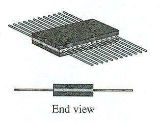
45 Fixed-Function Integrated Circuits Flat pack (FP)


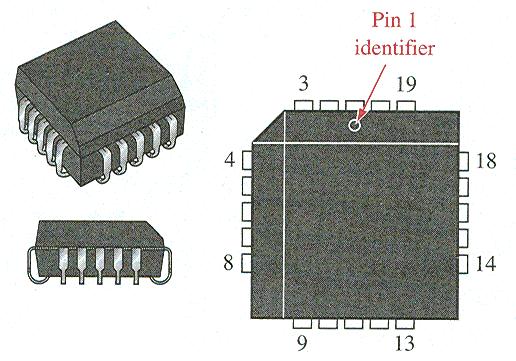
46 Fixed-Function Integrated Circuits Plastic-leaded chip carrier (PLCC)


47 Fixed-Function Integrated Circuits Leadless-ceramic chip carrier (LCCC)
48 Introduction to Programmable Logic
49 Introduction to Programmable Logic SPLD Simple programmable logic devices CPLD Complex programmable logic devices FPGA Field-programmable gate arrays
50 Introduction to Programmable Logic SPLD PAL (programmable array logic) GAL (generic array logic) PLA (programmable logic array) PROM (programmable read-only memory)
Aim. Lecture 1: Overview Digital Concepts. Objectives. 15 Lectures
 Aim Lecture 1: Overview Digital Concepts to give a first course in digital electronics providing you with both the knowledge and skills required to design simple digital circuits and preparing you for
Digital Logic ircuits Circuits Fundamentals I Fundamentals I
 Digital Logic Circuits Fundamentals I Fundamentals I 1 Digital and Analog Quantities Electronic circuits can be divided into two categories. Digital Electronics : deals with discrete values (= sampled
EE19D Digital Electronics. Lecture 1: General Introduction
 EE19D Digital Electronics Lecture 1: General Introduction 1 What are we going to discuss? Some Definitions Digital and Analog Quantities Binary Digits, Logic Levels and Digital Waveforms Introduction to
Digital Fundamentals 8/25/2016. Summary. Summary. Floyd. Chapter 1. Analog Quantities
 8/25/206 Digital Fundamentals Tenth Edition Floyd Chapter Analog Quantities Most natural quantities that we see are analog and vary continuously. Analog systems can generally handle higher power than digital
Digital Fundamentals
 Digital Fundamentals Tenth Edition Floyd Chapter 1 2009 Pearson Education, Upper 2008 Pearson Saddle River, Education NJ 07458. All Rights Reserved Objectives After completing this unit, you should be
Digital Fundamentals. Introductory Digital Concepts
 Digital Fundamentals Introductory Digital Concepts Objectives Explain the basic differences between digital and analog quantities Show how voltage levels are used to represent digital quantities Describe
Dr. Cahit Karakuş ANALOG SİNYALLER
 Dr. Cahit Karakuş ANALOG SİNYALLER Sinusoidal Waveform Mathematically it is represented as: Sinusoidal Waveform Unit of measurement for horizontal axis can be time, degrees or radians. Sinusoidal Waveform
CS302 - Digital Logic Design Glossary By
 CS302 - Digital Logic Design Glossary By ABEL : Advanced Boolean Expression Language; a software compiler language for SPLD programming; a type of hardware description language (HDL) Adder : A digital
CMOS Digital Logic Design with Verilog. Chapter1 Digital IC Design &Technology
 CMOS Digital Logic Design with Verilog Chapter1 Digital IC Design &Technology Chapter Overview: In this chapter we study the concept of digital hardware design & technology. This chapter deals the standard
Lecture 2. Digital Basics
 Lecture Digital Basics Peter Cheung Department of Electrical & Electronic Engineering Imperial College London URL: www.ee.ic.ac.uk/pcheung/teaching/de1_ee/ E-mail: p.cheung@imperial.ac.uk Lecture Slide
IES Digital Mock Test
 . The circuit given below work as IES Digital Mock Test - 4 Logic A B C x y z (a) Binary to Gray code converter (c) Binary to ECESS- converter (b) Gray code to Binary converter (d) ECESS- To Gray code
ECE380 Digital Logic
 ECE380 Digital Logic Implementation Technology: Standard Chips and Programmable Logic Devices Dr. D. J. Jackson Lecture 10-1 Standard chips A number of chips, each with a few logic gates, are commonly
Unit level 4 Credit value 15. Introduction. Learning Outcomes
 Unit 20: Unit code Digital Principles T/615/1494 Unit level 4 Credit value 15 Introduction While the broad field of electronics covers many aspects, it is digital electronics which now has the greatest
Engr354: Digital Logic Circuits
 Engr354: Digital Logic Circuits Chapter 3: Implementation Technology Curtis Nelson Chapter 3 Overview In this chapter you will learn about: How transistors are used as switches; Integrated circuit technology;
Number of Lessons:155 #14B (P) Electronics Technology with Digital and Microprocessor Laboratory Completion Time: 42 months
 Electronics Technology with Digital and Microprocessor Laboratory Completion Time: 42 months") PROGRESS RECORD Study your lessons in the order listed below. Number of Lessons:155 #14B (P) Electronics Technology with Digital and Microprocessor Laboratory Completion Time: 42 months 1 2330A Current
PROGRESS RECORD Study your lessons in the order listed below. Number of Lessons:155 #14B (P) Electronics Technology with Digital and Microprocessor Laboratory Completion Time: 42 months 1 2330A Current
Associate In Applied Science In Electronics Engineering Technology Expiration Date:
 PROGRESS RECORD Study your lessons in the order listed below. Associate In Applied Science In Electronics Engineering Technology Expiration Date: 1 2330A Current and Voltage 2 2330B Controlling Current
Department of Electrical and Electronics Engineering Logic Circuits Laboratory EXPERIMENT-5 COMBINATIONAL LOGIC CIRCUITS
 5.1 Preliminary Study Simulate experiment using an available tool and prepare the preliminary report. 5.2 Aim of the Experiment Implementation and examination of MULTIPLEXER and DEMULTIPLEXER circuits
Fan in: The number of inputs of a logic gate can handle.
 Subject Code: 17333 Model Answer Page 1/ 29 Important Instructions to examiners: 1) The answers should be examined by key words and not as word-to-word as given in the model answer scheme. 2) The model
DIGITAL INTEGRATED CIRCUITS A DESIGN PERSPECTIVE 2 N D E D I T I O N
 DIGITAL INTEGRATED CIRCUITS A DESIGN PERSPECTIVE 2 N D E D I T I O N Jan M. Rabaey, Anantha Chandrakasan, and Borivoje Nikolic CONTENTS PART I: THE FABRICS Chapter 1: Introduction (32 pages) 1.1 A Historical
Introduction (concepts and definitions)
") Objectives: Introduction (digital system design concepts and definitions). Advantages and drawbacks of digital techniques compared with analog. Digital Abstraction. Synchronous and Asynchronous Systems.
Objectives: Introduction (digital system design concepts and definitions). Advantages and drawbacks of digital techniques compared with analog. Digital Abstraction. Synchronous and Asynchronous Systems.
P a g e 1. Introduction
 P a g e 1 Introduction 1. Signals in digital form are more convenient than analog form for processing and control operation. 2. Real world signals originated from temperature, pressure, flow rate, force
Digital Electronic Concepts
 Western Technical College 10662137 Digital Electronic Concepts Course Outcome Summary Course Information Description Career Cluster Instructional Level Total Credits 4.00 Total Hours 108.00 This course
In this lecture: Lecture 8: ROM & Programmable Logic Devices
 In this lecture: Lecture 8: ROM Programmable Logic Devices Dr Pete Sedcole Department of EE Engineering Imperial College London http://caseeicacuk/~nps/ (Floyd, 3 5, 3) (Tocci 2, 24, 25, 27, 28, 3 34)
16 Multiplexers and De-multiplexers using gates and ICs. (74150, 74154)
") 16 Multiplexers and De-multiplexers using gates and ICs. (74150, 74154) Aim: To design multiplexers and De-multiplexers using gates and ICs. (74150, 74154) Components required: Digital IC Trainer kit,
16 Multiplexers and De-multiplexers using gates and ICs. (74150, 74154) Aim: To design multiplexers and De-multiplexers using gates and ICs. (74150, 74154) Components required: Digital IC Trainer kit,
Lecture Topics ECE 341. Lecture # 4. Decoder. 2-to-4 Decoder Circuit
 ECE 34 Lecture # 4 Instructor: Zeshan Chishti zeshan@ece.pdx.edu October 8, 24 Portland State University Lecture Topics Decoders Multiplexers Programmable Logic Devices (PLDs) General Structure of PLDs
Digital Design and System Implementation. Overview of Physical Implementations
 Digital Design and System Implementation Overview of Physical Implementations CMOS devices CMOS transistor circuit functional behavior Basic logic gates Transmission gates Tri-state buffers Flip-flops
EEE 301 Digital Electronics
 EEE 301 Digital Electronics Lecture 1 Course Contents Introduction to number systems and codes. Analysis and synthesis of digital logic circuits: Basic logic functions, Boolean algebra,combinational logic
Preface to Third Edition Deep Submicron Digital IC Design p. 1 Introduction p. 1 Brief History of IC Industry p. 3 Review of Digital Logic Gate
 Preface to Third Edition p. xiii Deep Submicron Digital IC Design p. 1 Introduction p. 1 Brief History of IC Industry p. 3 Review of Digital Logic Gate Design p. 6 Basic Logic Functions p. 6 Implementation
Objective Questions. (a) Light (b) Temperature (c) Sound (d) all of these
 Light (b) Temperature (c) Sound (d) all of these") Objective Questions Module 1: Introduction 1. Which of the following is an analog quantity? (a) Light (b) Temperature (c) Sound (d) all of these 2. Which of the following is a digital quantity? (a) Electrical
Objective Questions Module 1: Introduction 1. Which of the following is an analog quantity? (a) Light (b) Temperature (c) Sound (d) all of these 2. Which of the following is a digital quantity? (a) Electrical
Classification of Digital Circuits
 Classification of Digital Circuits Combinational logic circuits. Output depends only on present input. Sequential circuits. Output depends on present input and present state of the circuit. Combinational
ASTABLE MULTIVIBRATOR
 555 TIMER ASTABLE MULTIIBRATOR MONOSTABLE MULTIIBRATOR 555 TIMER PHYSICS (LAB MANUAL) PHYSICS (LAB MANUAL) 555 TIMER Introduction The 555 timer is an integrated circuit (chip) implementing a variety of
*************************************************************************
 for EE 151 Circuits I, EE 153 Circuits II, EE 121 Introduction to Electronic Devices, and CpE 111 Introduction to Computer Engineering. Missouri University of Science and Technology Introduction The required
Electronics. Digital Electronics
 Electronics Digital Electronics Introduction Unlike a linear, or analogue circuit which contains signals that are constantly changing from one value to another, such as amplitude or frequency, digital
Digital Applications (CETT 1415) Credit: 4 semester credit hours (3 hours lecture, 4 hours lab) Prerequisite: CETT 1403 & CETT 1405
 Credit: 4 semester credit hours (3 hours lecture, 4 hours lab) Prerequisite: CETT 1403 & CETT 1405") Digital Applications () Credit: 4 semester credit hours (3 hours lecture, 4 hours lab) Prerequisite: CETT 1403 & CETT 1405 Course Description This course covers digital techniques and numbering systems,
Digital Applications () Credit: 4 semester credit hours (3 hours lecture, 4 hours lab) Prerequisite: CETT 1403 & CETT 1405 Course Description This course covers digital techniques and numbering systems,
2009 Spring CS211 Digital Systems & Lab 1 CHAPTER 3: TECHNOLOGY (PART 2)
") 1 CHAPTER 3: IMPLEMENTATION TECHNOLOGY (PART 2) Whatwillwelearninthischapter? we learn in this 2 How transistors operate and form simple switches CMOS logic gates IC technology FPGAs and other PLDs Basic
1 CHAPTER 3: IMPLEMENTATION TECHNOLOGY (PART 2) Whatwillwelearninthischapter? we learn in this 2 How transistors operate and form simple switches CMOS logic gates IC technology FPGAs and other PLDs Basic
Combinational Circuits: Multiplexers, Decoders, Programmable Logic Devices
 Combinational Circuits: Multiplexers, Decoders, Programmable Logic Devices Lecture 5 Doru Todinca Textbook This chapter is based on the book [RothKinney]: Charles H. Roth, Larry L. Kinney, Fundamentals
PRESENTATION OF THE PROJECTX-FINAL LEVEL 1.
 Implementation of digital it frequency dividersid PRESENTATION OF THE PROJECTX-FINAL LEVEL 1. Why frequency divider? Motivation widely used in daily life Time counting (electronic clocks, traffic lights,
DIGITAL ELECTRONICS QUESTION BANK
 DIGITAL ELECTRONICS QUESTION BANK Section A: 1. Which of the following are analog quantities, and which are digital? (a) Number of atoms in a simple of material (b) Altitude of an aircraft (c) Pressure
4. Digital Measurement of Electrical Quantities
 4.1. Concept of Digital Systems Concept A digital system is a combination of devices designed for manipulating physical quantities or information represented in digital from, i.e. they can take only discrete
6.111 Lecture # 19. Controlling Position. Some General Features of Servos: Servomechanisms are of this form:
 6.111 Lecture # 19 Controlling Position Servomechanisms are of this form: Some General Features of Servos: They are feedback circuits Natural frequencies are 'zeros' of 1+G(s)H(s) System is unstable if
PE713 FPGA Based System Design
 PE713 FPGA Based System Design Why VLSI? Dept. of EEE, Amrita School of Engineering Why ICs? Dept. of EEE, Amrita School of Engineering IC Classification ANALOG (OR LINEAR) ICs produce, amplify, or respond
B.E. SEMESTER III (ELECTRICAL) SUBJECT CODE: X30902 Subject Name: Analog & Digital Electronics
 SUBJECT CODE: X30902 Subject Name: Analog & Digital Electronics") B.E. SEMESTER III (ELECTRICAL) SUBJECT CODE: X30902 Subject Name: Analog & Digital Electronics Sr. No. Date TITLE To From Marks Sign 1 To verify the application of op-amp as an Inverting Amplifier 2 To
B.E. SEMESTER III (ELECTRICAL) SUBJECT CODE: X30902 Subject Name: Analog & Digital Electronics Sr. No. Date TITLE To From Marks Sign 1 To verify the application of op-amp as an Inverting Amplifier 2 To
FPGA Based System Design
 FPGA Based System Design Reference Wayne Wolf, FPGA-Based System Design Pearson Education, 2004 Why VLSI? Integration improves the design: higher speed; lower power; physically smaller. Integration reduces
Analog to Digital Conversion
 Analog to Digital Conversion 02534567998 6 4 2 3 4 5 6 ANALOG to DIGITAL CONVERSION Analog variation (Continuous, smooth variation) Digitized Variation (Discrete set of points) N2 N1 Digitization applied
The operational amplifier
 The operational amplifier Long before the advent of digital electronic technology, computers were built to electronically perform calculations by employing voltages and currents to represent numerical
1 Analog and Digital Communication Lab
 1 2 Amplitude modulator trainer kit diagram AM Detector trainer kit Diagram 3 4 Calculations: 5 Result: 6 7 8 Balanced modulator circuit diagram Generation of DSB-SC 1. For the same circuit apply the modulating
UMAINE ECE Morse Code ROM and Transmitter at ISM Band Frequency
 UMAINE ECE Morse Code ROM and Transmitter at ISM Band Frequency Jamie E. Reinhold December 15, 2011 Abstract The design, simulation and layout of a UMAINE ECE Morse code Read Only Memory and transmitter
Lecture #1. Course Overview
 Lecture #1 OUTLINE Course overview Introduction: integrated circuits Analog vs. digital signals Lecture 1, Slide 1 Course Overview EECS 40: One of five EECS core courses (with 20, 61A, 61B, and 61C) introduces
Chapter 2 Analog-to-Digital Conversion...
 Chapter... 5 This chapter examines general considerations for analog-to-digital converter (ADC) measurements. Discussed are the four basic ADC types, providing a general description of each while comparing
Amplitude modulator trainer kit diagram
 Amplitude modulator trainer kit diagram AM Detector trainer kit Diagram Calculations: Result: Pre lab test (20) Observation (20) Simulation (20) Remarks & Signature with Date Circuit connection (30) Result
Lecture 02: Digital Logic Review
 CENG 3420 Lecture 02: Digital Logic Review Bei Yu byu@cse.cuhk.edu.hk CENG3420 L02 Digital Logic. 1 Spring 2017 Review: Major Components of a Computer CENG3420 L02 Digital Logic. 2 Spring 2017 Review:
Name: Class: Date: 1. As more electronic systems have been designed using digital technology, devices have become smaller and less powerful.
 Name: Class: Date: DE Midterm Review 2 True/False Indicate whether the statement is true or false. 1. As more electronic systems have been designed using digital technology, devices have become smaller
1 Signals and systems, A. V. Oppenhaim, A. S. Willsky, Prentice Hall, 2 nd edition, FUNDAMENTALS. Electrical Engineering. 2.
 1 Signals and systems, A. V. Oppenhaim, A. S. Willsky, Prentice Hall, 2 nd edition, 1996. FUNDAMENTALS Electrical Engineering 2.Processing - Analog data An analog signal is a signal that varies continuously.
Basic Logic Circuits
 Basic Logic Circuits Required knowledge Measurement of static characteristics of nonlinear circuits. Measurement of current consumption. Measurement of dynamic properties of electrical circuits. Definitions
UNIT-1. Basic signal processing operations in digital communication
 UNIT-1 Lecture-1 Basic signal processing operations in digital communication The three basic elements of every communication systems are Transmitter, Receiver and Channel. The Overall purpose of this system
Code No: R Set No. 1
 Code No: R05310402 Set No. 1 1. (a) What are the parameters that are necessary to define the electrical characteristics of CMOS circuits? Mention the typical values of a CMOS NAND gate. (b) Design a CMOS
For reference, the readers can browse through our ELECTRONIC CIRCUITS tutorial at https://www.tutorialspoint.com/electronic_circuits/index.htm.
 About the Tutorial In this tutorial, we will discuss all the important circuits that are related to pulse signals. In addition, we will also cover the circuits that generate and work with pulse signals.
Techniques for Pixel Level Analog to Digital Conversion
 Techniques for Level Analog to Digital Conversion Boyd Fowler, David Yang, and Abbas El Gamal Stanford University Aerosense 98 3360-1 1 Approaches to Integrating ADC with Image Sensor Chip Level Image
ENGR 210 Lab 12: Analog to Digital Conversion
 ENGR 210 Lab 12: Analog to Digital Conversion In this lab you will investigate the operation and quantization effects of an A/D and D/A converter. A. BACKGROUND 1. LED Displays We have been using LEDs
CSCD 433 Network Programming Fall Lecture 5 Physical Layer Continued
 CSCD 433 Network Programming Fall 2016 Lecture 5 Physical Layer Continued 1 Topics Definitions Analog Transmission of Digital Data Digital Transmission of Analog Data Multiplexing 2 Different Types of
DUAL STEPPER MOTOR DRIVER
 DUAL STEPPER MOTOR DRIVER GENERAL DESCRIPTION The is a switch-mode (chopper), constant-current driver with two channels: one for each winding of a two-phase stepper motor. is equipped with a Disable input
TECHNO INDIA BATANAGAR (DEPARTMENT OF ELECTRONICS & COMMUNICATION ENGINEERING) QUESTION BANK- 2018
 QUESTION BANK- 2018") TECHNO INDIA BATANAGAR (DEPARTMENT OF ELECTRONICS & COMMUNICATION ENGINEERING) QUESTION BANK- 2018 Paper Setter Detail Name Designation Mobile No. E-mail ID Raina Modak Assistant Professor 6290025725 raina.modak@tib.edu.in
TECHNO INDIA BATANAGAR (DEPARTMENT OF ELECTRONICS & COMMUNICATION ENGINEERING) QUESTION BANK- 2018 Paper Setter Detail Name Designation Mobile No. E-mail ID Raina Modak Assistant Professor 6290025725 raina.modak@tib.edu.in
CS302 Digital Logic Design Solved Objective Midterm Papers For Preparation of Midterm Exam
 CS302 Digital Logic Design Solved Objective Midterm Papers For Preparation of Midterm Exam MIDTERM EXAMINATION 2011 (October-November) Q-21 Draw function table of a half adder circuit? (2) Answer: - Page
Digital Fundamentals. Logic gates
 Digital Fundamentals Logic gates Objectives Describe the operation of the inverter, the AND gate, and the OR gate Describe the operation of the NAND gate and the NOR gate Express the operation of the NOT,
Department of Electronics & Telecommunication Engg. LAB MANUAL. B.Tech V Semester [ ] (Branch: ETE)
![Department of Electronics & Telecommunication Engg. LAB MANUAL. B.Tech V Semester [ ] (Branch: ETE)](/thumbs/86/93078052.jpg "Department of Electronics & Telecommunication Engg. LAB MANUAL. B.Tech V Semester [ ] (Branch: ETE)") Department of Electronics & Telecommunication Engg. LAB MANUAL SUBJECT:-DIGITAL COMMUNICATION SYSTEM [BTEC-501] B.Tech V Semester [2013-14] (Branch: ETE) KCT COLLEGE OF ENGG & TECH., FATEHGARH PUNJAB TECHNICAL
Department of Electronics & Telecommunication Engg. LAB MANUAL SUBJECT:-DIGITAL COMMUNICATION SYSTEM [BTEC-501] B.Tech V Semester [2013-14] (Branch: ETE) KCT COLLEGE OF ENGG & TECH., FATEHGARH PUNJAB TECHNICAL
Digital Electronics 8. Multiplexer & Demultiplexer
 1 Module -8 Multiplexers and Demultiplexers 1 Introduction 2 Principles of Multiplexing and Demultiplexing 3 Multiplexer 3.1 Types of multiplexer 3.2 A 2 to 1 multiplexer 3.3 A 4 to 1 multiplexer 3.4 Multiplex
COMBINATIONAL and SEQUENTIAL LOGIC CIRCUITS Hardware implementation and software design
 PH-315 COMINATIONAL and SEUENTIAL LOGIC CIRCUITS Hardware implementation and software design A La Rosa I PURPOSE: To familiarize with combinational and sequential logic circuits Combinational circuits
Chapter 4: The Building Blocks: Binary Numbers, Boolean Logic, and Gates
 Chapter 4: The Building Blocks: Binary Numbers, Boolean Logic, and Gates Objectives In this chapter, you will learn about The binary numbering system Boolean logic and gates Building computer circuits
UNIT-IV Combinational Logic
 UNIT-IV Combinational Logic Introduction: The signals are usually represented by discrete bands of analog levels in digital electronic circuits or digital electronics instead of continuous ranges represented
Chapter-1: Introduction
 Chapter-1: Introduction The purpose of a Communication System is to transport an information bearing signal from a source to a user destination via a communication channel. MODEL OF A COMMUNICATION SYSTEM
Digital Applications (CETT 1415) Credit: 4 semester credit hours (3 hours lecture, 4 hours lab) Prerequisite: CETT 1403 & CETT 1405
 Credit: 4 semester credit hours (3 hours lecture, 4 hours lab) Prerequisite: CETT 1403 & CETT 1405") Digital Applications (CETT 1415) Credit: 4 semester credit hours (3 hours lecture, 4 hours lab) Prerequisite: CETT 1403 & CETT 1405 Course Description This course covers digital techniques and numbering
Digital Applications (CETT 1415) Credit: 4 semester credit hours (3 hours lecture, 4 hours lab) Prerequisite: CETT 1403 & CETT 1405 Course Description This course covers digital techniques and numbering
Combinational Logic Circuits. Combinational Logic
 Combinational Logic Circuits The outputs of Combinational Logic Circuits are only determined by the logical function of their current input state, logic 0 or logic 1, at any given instant in time. The
EECS150 - Digital Design Lecture 2 - CMOS
 EECS150 - Digital Design Lecture 2 - CMOS August 29, 2002 John Wawrzynek Fall 2002 EECS150 - Lec02-CMOS Page 1 Outline Overview of Physical Implementations CMOS devices Announcements/Break CMOS transistor
DIGITAL CIRCUITS AND SYSTEMS ASSIGNMENTS 1 SOLUTIONS
 DIGITAL CIRCUITS AND SYSTEMS ASSIGNMENTS 1 SOLUTIONS 1. Analog signal varies continuously between two amplitudes over the given interval of time. Between these limits of amplitude and time, the signal
In this lecture. System Model Power Penalty Analog transmission Digital transmission
 System Model Power Penalty Analog transmission Digital transmission In this lecture Analog Data Transmission vs. Digital Data Transmission Analog to Digital (A/D) Conversion Digital to Analog (D/A) Conversion
Lab 2 Revisited Exercise
 Lab 2 Revisited Exercise +15V 100k 1K 2N2222 Wire up led display Note the ground leads LED orientation 6.091 IAP 2008 Lecture 3 1 Comparator, Oscillator +5 +15 1k 2 V- 7 6 Vin 3 V+ 4 V o Notice that power
CS61c: Introduction to Synchronous Digital Systems
 CS61c: Introduction to Synchronous Digital Systems J. Wawrzynek March 4, 2006 Optional Reading: P&H, Appendix B 1 Instruction Set Architecture Among the topics we studied thus far this semester, was the
Combinational logic. ! Regular logic: multiplexers, decoders, LUTs and FPGAs. ! Switches, basic logic and truth tables, logic functions
 Combinational logic! Switches, basic logic and truth tables, logic functions! Algebraic expressions to gates! Mapping to different gates! Discrete logic gate components (used in labs and 2)! Canonical
Computer Architecture and Organization:
 Computer Architecture and Organization: L03: Register transfer and System Bus By: A. H. Abdul Hafez Abdul.hafez@hku.edu.tr, ah.abdulhafez@gmail.com 1 CAO, by Dr. A.H. Abdul Hafez, CE Dept. HKU Outlines
BPSK Modulation and Demodulation Scheme on Spartan-3 FPGA
 BPSK Modulation and Demodulation Scheme on Spartan-3 FPGA Mr. Pratik A. Bhore 1, Miss. Mamta Sarde 2 pbhore3@gmail.com1, mmsarde@gmail.com2 Department of Electronics & Communication Engineering Abha Gaikwad-Patil
Analog to Digital Converters
 Analog to Digital Converters By: Byron Johns, Danny Carpenter Stephanie Pohl, Harry Bo Marr http://ume.gatech.edu/mechatronics_course/fadc_f05.ppt (unless otherwise marked) Presentation Outline Introduction:
COMBINATIONAL CIRCUIT
 Combinational circuit is a circuit in which we combine the different gates in the circuit, for example encoder, decoder, multiplexer and demultiplexer. Some of the characteristics of combinational circuits
Digital multimeter IENGINEERS- CONSULTANTS LECTURE NOTES SERIES ELECTRONICS ENGINEERING 1 YEAR UPTU. Page 1
 Digital multimeter Measurement of any quantity is a result of comparison between the quantity to be measured and a definite world wide standard. The instruments which are used for such comparison are called
DIGITAL COMMUNICATIONS LAB
 DIGITAL COMMUNICATIONS LAB List of Experiments: 1. PCM Generation and Detection. 2. Differential Pulse Code modulation. 3. Delta modulation. 4. Time Division Multiplexing of 2band Limited Signals. 5. Frequency
ELECTRONICS WITH DISCRETE COMPONENTS
 ELECTRONICS WITH DISCRETE COMPONENTS Enrique J. Galvez Department of Physics and Astronomy Colgate University WILEY John Wiley & Sons, Inc. ^ CONTENTS Preface vii 1 The Basics 1 1.1 Foreword: Welcome to
512 x 8 Registered PROM
 512 x 8 Registered PROM Features CMOS for optimum speed/power High speed 25 ns address set-up 12 ns clock to output Low power 495 mw (Commercial) 660 mw (Military) Synchronous and asynchronous output enables
CSCD 433 Network Programming Fall Lecture 5 Physical Layer Continued
 CSCD 433 Network Programming Fall 2016 Lecture 5 Physical Layer Continued 1 Topics Definitions Analog Transmission of Digital Data Digital Transmission of Analog Data Multiplexing 2 Different Types of
LBI-38392C IC DATA MAINTENANCE MANUAL LOGIC BOARD U707 OCTAL DATA LATCH 19D902172G1 & G2 TABLE OF CONTENTS
 LBI-38392C MAINTENANCE MANUAL LOGIC BOARD 19D902172G1 & G2 U707 OCTAL DATA LATCH IC DATA TABLE OF CONTENTS Page DESCRIPTION........................................... Front.. Cover CIRCUIT ANALYSIS........................................
Digital Controller Chip Set for Isolated DC Power Supplies
 Digital Controller Chip Set for Isolated DC Power Supplies Aleksandar Prodic, Dragan Maksimovic and Robert W. Erickson Colorado Power Electronics Center Department of Electrical and Computer Engineering
Digital Logic Circuits
 Digital Logic Circuits Let s look at the essential features of digital logic circuits, which are at the heart of digital computers. Learning Objectives Understand the concepts of analog and digital signals
Monostable multivibrators
 Monostable multivibrators We've already seen one example of a monostable multivibrator in use: the pulse detector used within the circuitry of flip-flops, to enable the latch portion for a brief time when
GOVERNMENT OF KARNATAKA KARNATAKA STATE PRE-UNIVERSITY EDUCATION EXAMINATION BOARD II YEAR PUC EXAMINATION MARCH-2013 SCHEME OF VALUATION
 GOVERNMENT OF KARNATAKA KARNATAKA STATE PRE-UNIVERSITY EDUCATION EXAMINATION BOARD II YEAR PUC EXAMINATION MARCH-03 SCHEME OF VALUATION Subject Code: 0 Subject: PART - A 0. What does the arrow mark indicate
PHYS225 Lecture 22. Electronic Circuits
 PHYS225 Lecture 22 Electronic Circuits Last lecture Digital to Analog Conversion DAC Converts digital signal to an analog signal Computer control of everything! Various types/techniques for conversion
INTRODUCTION TO DIGITAL CONCEPT
 COURSE / CODE DIGITAL SYSTEM FUNDAMENTALS (ECE 421) DIGITAL ELECTRONICS FUNDAMENTAL (ECE 422) INTRODUCTION TO DIGITAL CONCEPT Digital and Analog Quantities Digital relates to data in the form of digits,
Reference. Wayne Wolf, FPGA-Based System Design Pearson Education, N Krishna Prakash,, Amrita School of Engineering
 FPGA Fabrics Reference Wayne Wolf, FPGA-Based System Design Pearson Education, 2004 CPLD / FPGA CPLD Interconnection of several PLD blocks with Programmable interconnect on a single chip Logic blocks executes
The figures and the logic used for the MATLAB are given below.
 MATLAB FIGURES & PROGRAM LOGIC: Transmitter: The figures and the logic used for the MATLAB are given below. Binary Data Sequence: For our project we assume that we have the digital binary data stream.
DEPARTMENT OF ELECTRICAL ENGINEERING LAB WORK EE301 ELECTRONIC CIRCUITS
 DEPARTMENT OF ELECTRICAL ENGINEERING LAB WORK EE301 ELECTRONIC CIRCUITS EXPERIMENT : 4 TITLE : 555 TIMERS OUTCOME : Upon completion of this unit, the student should be able to: 1. gain experience with
Chapter 3 Combinational Logic Design
 Logic and Computer Design Fundamentals Chapter 3 Combinational Logic Design Part 2 Combinational Logic Overview Part -Implementation Technology and Logic Design Design Concepts Fundamental concepts of
Ch 5 Hardware Components for Automation
 Ch 5 Hardware Components for Automation Sections: 1. Sensors 2. Actuators 3. Analog-to-Digital Conversion 4. Digital-to-Analog Conversion 5. Input/Output Devices for Discrete Data Computer-Process Interface
LOGIC DIAGRAM: HALF ADDER TRUTH TABLE: A B CARRY SUM. 2012/ODD/III/ECE/DE/LM Page No. 1
 LOGIC DIAGRAM: HALF ADDER TRUTH TABLE: A B CARRY SUM K-Map for SUM: K-Map for CARRY: SUM = A B + AB CARRY = AB 22/ODD/III/ECE/DE/LM Page No. EXPT NO: DATE : DESIGN OF ADDER AND SUBTRACTOR AIM: To design