Ch 5 Hardware Components for Automation
|
|
|
- Johnathan Conley
- 6 years ago
- Views:
Transcription
1 Ch 5 Hardware Components for Automation Sections: 1. Sensors 2. Actuators 3. Analog-to-Digital Conversion 4. Digital-to-Analog Conversion 5. Input/Output Devices for Discrete Data
2 Computer-Process Interface To implement process control, the computer must collect data from and transmit signals to the production process Components required to implement the interface: Sensors to measure continuous and discrete process variables Actuators to drive continuous and discrete process parameters Devices for ADC and DAC I/O devices for discrete data

3 Computer Process Control System
4 Sensors A sensor is a transducer that converts a physical stimulus from one form into a more useful form to measure the stimulus Two basic categories: 1. Analog 2. Discrete Binary Digital (e.g., pulse counter)
5 Sensor Transfer Function The relationship between the value of the physical stimulus and the value of the signal produced by the sensor in response to the stimulus S = f(s) where S = output signal, s = stimulus, and f(s) is the functional relationship between them Ideal functional form is simple proportional relationship: S = C + ms
6 Actuators Hardware devices that convert a controller command signal into a change in a physical parameter The change is usually mechanical (e.g., position or velocity) An actuator is a transducer because it changes one type of physical quantity into some alternative form An actuator is usually activated by a low-level command signal, so an amplifier may be required to provide sufficient power to drive the actuator
7 Types of Actuators 1. Electrical actuators Electric motors DC servomotors AC motors Stepper motors Solenoids 2. Hydraulic actuators Use hydraulic fluid to amplify the controller command signal 3. Pneumatic actuators Use compressed air as the driving force

8 A Rotating Electric Motor
9 Torque-Speed Curve of a DC Servomotor and Load Torque Plot
10 Typical Torque-Speed Curve of a Stepper Motor
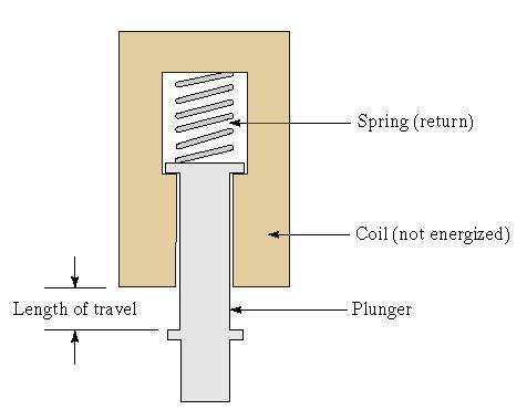
11 Solenoid
12 Cylinder and Piston: (a) Single-Acting and (b) Double-Acting (a) (b)
13 Analog-to-Digital Conversion An ADC converts a continuous analog signal from transducer into digital code for use by computer ADC consists of three phases: 1. Sampling converts the continuous signal into a series of discrete analog signals at periodic intervals 2. Quantization each discrete analog is converted into one of a finite number of (previously defined) discrete amplitude levels 3. Encoding discrete amplitude levels are converted into digital code
14 Hardware Devices in Analog-to-Digital Conversion
15 Features of an ADC Sampling rate rate at which continuous analog signal is polled Conversion time how long it takes to convert the sampled signal to digital code Resolution depends on number of quantization levels Conversion method means by which analog signal is encoded into digital equivalent Example Successive approximation method
16 Analog Signal Converted into a Series of Discrete Data by A-to-D Converter
17 Successive Approximation Method A series of trial voltages are successively compared to the input signal whose value is unknown Number of trial voltages = number of bits used to encode the signal First trial voltage is 1/2 the full scale range of the ADC If the remainder of the input voltage exceeds the trial voltage, then a bit value of 1 is entered, if less than trial voltage then a bit value of zero is entered The successive bit values, multiplied by their respective trial voltages and added, becomes the encoded value of the input signal
18 Successive Approximation Method Example for input voltage of 6.8 V
19 Digital-to-Analog Conversion Converts the digital output of the computer into a continuous analog signal to drive an analog actuator (or other analog device) DAC consists of two steps: 1. Decoding digital output of computer is converted into a series of analog values at discrete moments in time 2. Data holding each successive value is changed into a continuous signal that lasts until the next sampling interval
20 Data Holding Step in DAC: (a) Zero- Order Hold and (b) First-Order Hold (a) (b)
21 Input/Output Devices for Discrete Data Binary data: Contact input interface input data to computer Contact output interface output data from computer Discrete data other than binary: Contact input interface input data to computer Contact output interface output data from computer Pulse data: Pulse counters - input data to computer Pulse generators - output data from computer
22 Contact Input/Output Interfaces Contact input interface series of contacts that are open or closed to indicate the status of individual binary devices such as limit switches and valves The computer periodically scans the contacts to update values in memory Can also be used for discrete data other than binary (e.g., a photoelectric sensor array) Contact output interface communicates on/off signals from the computer to the process Values are maintained until changed by the computer
23 Pulse Counters and Generators Pulse counter converts a series of pulses (pulse train) into a digital value Digital value is then entered into the computer through its input channel Most common counting electrical pulses Used for both counting and measurement applications Pulse generator a device that produces a series of electrical signals The number of pulses or frequency of the pulse train is specified by the computer
Actuators in Automatic Control System
 Actuators in Automatic Control System Measurement & Control Systems Transducers Measurement Process Actuators Data processing Requirement analyses Decision making Control actions CONTROL action requires
 Code No: M0326 /R07 Set No. 1 1. Define Mechatronics and explain the application of Mechatronics in CNC Machine tools and Computer Integrated Manufacturing (CIM). 2. (a) What are the various Filters that
P a g e 1. Introduction
 P a g e 1 Introduction 1. Signals in digital form are more convenient than analog form for processing and control operation. 2. Real world signals originated from temperature, pressure, flow rate, force
CIS009-2, Mechatronics Signals & Motors
 CIS009-2, Signals & Motors Bedfordshire 13 th December 2012 Outline 1 2 3 4 5 6 7 8 3 Signals Two types of signals exist: 4 Bedfordshire 52 Analogue signal In an analogue signal voltages and currents continuously
ACTUATORS AND SENSORS. Joint actuating system. Servomotors. Sensors
 ACTUATORS AND SENSORS Joint actuating system Servomotors Sensors JOINT ACTUATING SYSTEM Transmissions Joint motion low speeds high torques Spur gears change axis of rotation and/or translate application
Analog to Digital Conversion
 Analog to Digital Conversion 02534567998 6 4 2 3 4 5 6 ANALOG to DIGITAL CONVERSION Analog variation (Continuous, smooth variation) Digitized Variation (Discrete set of points) N2 N1 Digitization applied
Computerized Data Acquisition Systems. Chapter 4
 Computerized Data Acquisition Systems Chapter 4 Data Acquisition - Objectives State and discuss in terms a bright high school student would understand the following definitions related to data acquisition
A-D and D-A Converters
 Chapter 5 A-D and D-A Converters (No mathematical derivations) 04 Hours 08 Marks When digital devices are to be interfaced with analog devices (or vice a versa), Digital to Analog converter and Analog
UNIT III Data Acquisition & Microcontroller System. Mr. Manoj Rajale
 UNIT III Data Acquisition & Microcontroller System Mr. Manoj Rajale Syllabus Interfacing of Sensors / Actuators to DAQ system, Bit width, Sampling theorem, Sampling Frequency, Aliasing, Sample and hold
Analog-Digital Interface
 Analog-Digital Interface Tuesday 24 November 15 Summary Previous Class Dependability Today: Redundancy Error Correcting Codes Analog-Digital Interface Converters, Sensors / Actuators Sampling DSP Frequency
Digital to Analog Conversion. Data Acquisition
 Digital to Analog Conversion (DAC) Digital to Analog Conversion Data Acquisition DACs or D/A converters are used to convert digital signals representing binary numbers into proportional analog voltages.
ELG3336 Design of Mechatronics System
 ELG3336 Design of Mechatronics System Elements of a Data Acquisition System 2 Analog Signal Data Acquisition Hardware Your Signal Data Acquisition DAQ Device System Computer Cable Terminal Block Data Acquisition
Sorting Line with Detection 9V
 536628 Sorting Line with Detection 9V I2 O8 I1 I3 C1 I5 I6 I4 Not in the picture: O5, O6, O7, O8 Circuit layout for Sorting Line with Detection Terminal no. Function Input/Output 1 color sensor I1 2 phototransistor
DC motor control using arduino
 DC motor control using arduino 1) Introduction: First we need to differentiate between DC motor and DC generator and where we can use it in this experiment. What is the main different between the DC-motor,
ANALOG TO DIGITAL (ADC) and DIGITAL TO ANALOG CONVERTERS (DAC)
 and DIGITAL TO ANALOG CONVERTERS (DAC)") COURSE / CODE DIGITAL SYSTEM FUNDAMENTALS (ECE421) DIGITAL ELECTRONICS FUNDAMENTAL (ECE422) ANALOG TO DIGITAL (ADC) and DIGITAL TO ANALOG CONVERTERS (DAC) Connecting digital circuitry to sensor devices
COURSE / CODE DIGITAL SYSTEM FUNDAMENTALS (ECE421) DIGITAL ELECTRONICS FUNDAMENTAL (ECE422) ANALOG TO DIGITAL (ADC) and DIGITAL TO ANALOG CONVERTERS (DAC) Connecting digital circuitry to sensor devices
Data Converters. Dr.Trushit Upadhyaya EC Department, CSPIT, CHARUSAT
 Data Converters Dr.Trushit Upadhyaya EC Department, CSPIT, CHARUSAT Purpose To convert digital values to analog voltages V OUT Digital Value Reference Voltage Digital Value DAC Analog Voltage Analog Quantity:
Robotic Vehicle Design
 Robotic Vehicle Design Actuators, control and interfacing Jim Keller July 19, 2005 What are actuators and Why are they needed? Computers/microprocessors are good at calculating what should be done to control
Stepping motor controlling apparatus
 Stepping motor controlling apparatus Ngoc Quy, Le*, and Jae Wook, Jeon** School of Information and Computer Engineering, SungKyunKwan University, 300 Chunchundong, Jangangu, Suwon, Gyeonggi 440746, Korea
Draw the symbol and state the applications of : 1) Push button switch 2) 3) Solenoid valve 4) Limit switch ( 1m each) Ans: 1) Push Button
 Push button switch 2) 3) Solenoid valve 4) Limit switch ( 1m each) Ans: 1) Push Button") Subject Code: 17641Model AnswerPage 1 of 16 Important suggestions to examiners: 1) The answers should be examined by key words and not as word-to-word as given in the model answer scheme. 2) The model
Subject Code: 17641Model AnswerPage 1 of 16 Important suggestions to examiners: 1) The answers should be examined by key words and not as word-to-word as given in the model answer scheme. 2) The model
Measurement, Sensors, and Data Acquisition in the Two-Can System
 Measurement, Sensors, and Data Acquisition in the Two-Can System Prof. R.G. Longoria Updated Fall 2010 Goal of this week s lab Gain familiarity with using sensors Gain familiarity with using DAQ hardware
Introduction. ELCT903, Sensor Technology Electronics and Electrical Engineering Department 1. Dr.-Eng. Hisham El-Sherif
 Introduction In automation industry every mechatronic system has some sensors to measure the status of the process variables. The analogy between the human controlled system and a computer controlled system
CS545 Contents XIV. Components of a Robotic System. Signal Processing. Reading Assignment for Next Class
 CS545 Contents XIV Components of a Robotic System Power Supplies and Power Amplifiers Actuators Transmission Sensors Signal Processing Linear filtering Simple filtering Optimal filtering Reading Assignment
PRESENTED BY HUMANOID IIT KANPUR
 SENSORS & ACTUATORS Robotics Club (Science and Technology Council, IITK) PRESENTED BY HUMANOID IIT KANPUR October 11th, 2017 WHAT ARE WE GOING TO LEARN!! COMPARISON between Transducers Sensors And Actuators.
Signal Paths from Analog to Digital
 CHAPTER 1 Signal Paths from Analog to Digital Introduction Designers of analog electronic control systems have continually faced following obstacles in arriving at a satisfactory design: 1. Instability
Hydraulic Actuator Control Using an Multi-Purpose Electronic Interface Card
 Hydraulic Actuator Control Using an Multi-Purpose Electronic Interface Card N. KORONEOS, G. DIKEAKOS, D. PAPACHRISTOS Department of Automation Technological Educational Institution of Halkida Psaxna 34400,
Analog-to-Digital Converter (ADC) And Digital-to-Analog Converter (DAC)
 And Digital-to-Analog Converter (DAC)") 1 Analog-to-Digital Converter (ADC) And Digital-to-Analog Converter (DAC) 2 1. DAC In an electronic circuit, a combination of high voltage (+5V) and low voltage (0V) is usually used to represent a binary
1 Analog-to-Digital Converter (ADC) And Digital-to-Analog Converter (DAC) 2 1. DAC In an electronic circuit, a combination of high voltage (+5V) and low voltage (0V) is usually used to represent a binary
Chapter 2 Analog-to-Digital Conversion...
 Chapter... 5 This chapter examines general considerations for analog-to-digital converter (ADC) measurements. Discussed are the four basic ADC types, providing a general description of each while comparing
Pulse Code Modulation
 Pulse Code Modulation Modulation is the process of varying one or more parameters of a carrier signal in accordance with the instantaneous values of the message signal. The message signal is the signal
Chapter 5: Signal conversion
 Chapter 5: Signal conversion Learning Objectives: At the end of this topic you will be able to: explain the need for signal conversion between analogue and digital form in communications and microprocessors
Job Sheet 2 Servo Control
 Job Sheet 2 Servo Control Electrical actuators are replacing hydraulic actuators in many industrial applications. Electric servomotors and linear actuators can perform many of the same physical displacement
Self contained servo drive CLDP Technical data sheet
 voith.com Self contained servo drive CLDP Technical data sheet Advantages + + High energy efficiency + + High dynamics + + Oil free power pack and piping are not necessary + + Sensors used provide the
Outline. Analog/Digital Conversion
 Analog/Digital Conversion The real world is analog. Interfacing a microprocessor-based system to real-world devices often requires conversion between the microprocessor s digital representation of values
Data acquisition and instrumentation. Data acquisition
 Data acquisition and instrumentation START Lecture Sam Sadeghi Data acquisition 1 Humanistic Intelligence Body as a transducer,, data acquisition and signal processing machine Analysis of physiological
Application of Integrated Controller MICREX-SX to a Motion Control System
 Application of Integrated Controller MICREX-SX to a Motion Control System Tadakatsu Aida Takashi Ida Yasutaka Tominaga 1. Introduction A scalable multi-controller SPH [hardware programmable controller
Microcomputer Systems 1. Introduction to DSP S
 Microcomputer Systems 1 Introduction to DSP S Introduction to DSP s Definition: DSP Digital Signal Processing/Processor It refers to: Theoretical signal processing by digital means (subject of ECE3222,
Advantages of Analog Representation. Varies continuously, like the property being measured. Represents continuous values. See Figure 12.
 Analog Signals Signals that vary continuously throughout a defined range. Representative of many physical quantities, such as temperature and velocity. Usually a voltage or current level. Digital Signals
Digital Logic ircuits Circuits Fundamentals I Fundamentals I
 Digital Logic Circuits Fundamentals I Fundamentals I 1 Digital and Analog Quantities Electronic circuits can be divided into two categories. Digital Electronics : deals with discrete values (= sampled
High-speed and High-precision Motion Controller
 High-speed and High-precision Motion Controller - KSMC - Definition High-Speed Axes move fast Execute the controller ( position/velocity loop, current loop ) at high frequency High-Precision High positioning
Dr. Cahit Karakuş ANALOG SİNYALLER
 Dr. Cahit Karakuş ANALOG SİNYALLER Sinusoidal Waveform Mathematically it is represented as: Sinusoidal Waveform Unit of measurement for horizontal axis can be time, degrees or radians. Sinusoidal Waveform
MICROPROCESSOR BASED CONTROLLERS
 MICROPROCESSOR BASED CONTROLLERS INPUTS Digital Analog TTL Pulse Keyboard Serial Microprocessor Based Controller OUTPUTS On/Off Analog PWM Serial Graphical Text RS232 Abstract: A controller is a system
Analog I/O. ECE 153B Sensor & Peripheral Interface Design Winter 2016
 Analog I/O ECE 153B Sensor & Peripheral Interface Design Introduction Anytime we need to monitor or control analog signals with a digital system, we require analogto-digital (ADC) and digital-to-analog
The Allen-Bradley Servo Interface Module (Cat. No SF1) when used with the Micro Controller (Cat. No UC1) can control single axis
 when used with the Micro Controller (Cat. No UC1) can control single axis") Table of Contents The Allen-Bradley Servo Interface Module (Cat. No. 1771-SF1) when used with the Micro Controller (Cat. No. 1771-UC1) can control single axis positioning systems such as found in machine
Table of Contents The Allen-Bradley Servo Interface Module (Cat. No. 1771-SF1) when used with the Micro Controller (Cat. No. 1771-UC1) can control single axis positioning systems such as found in machine
Electro-hydraulic Servo Valve Systems
 Fluidsys Training Centre, Bangalore offers an extensive range of skill-based and industry-relevant courses in the field of Pneumatics and Hydraulics. For more details, please visit the website: https://fluidsys.org
Digital multimeter IENGINEERS- CONSULTANTS LECTURE NOTES SERIES ELECTRONICS ENGINEERING 1 YEAR UPTU. Page 1
 Digital multimeter Measurement of any quantity is a result of comparison between the quantity to be measured and a definite world wide standard. The instruments which are used for such comparison are called
Digital Signal Processing +
 Digital Signal Processing + Nikil Dutt UC Irvine ICS 212 Winter 2005 + Material adapted from Tony Givargis & Rajesh Gupta Templates from Prabhat Mishra ICS212 WQ05 (Dutt) DSP 1 Introduction Any interesting
combine regular DC-motors with a gear-box and an encoder/potentiometer to form a position control loop can only assume a limited range of angular
 Embedded Control Applications II MP10-1 Embedded Control Applications II MP10-2 week lecture topics 10 Embedded Control Applications II - Servo-motor control - Stepper motor control - The control of a
EEE3410 Microcontroller Applications Department of Electrical Engineering. Lecture 10. Analogue Interfacing. Vocational Training Council, Hong Kong.
 Department of Electrical Engineering Lecture 10 Analogue Interfacing 1 In this Lecture. Interface 8051 with the following Input/Output Devices Transducer/Sensors Analogue-to-Digital Conversion (ADC) Digital-to-Analogue
Developer Techniques Sessions
 1 Developer Techniques Sessions Physical Measurements and Signal Processing Control Systems Logging and Networking 2 Abstract This session covers the technologies and configuration of a physical measurement
Analog Inputs and Outputs
 Analog Inputs and Outputs PLCs must also work with continuous or analog signals. Typical analog signals are 0-10 VDC or 4-20 ma. Analog signals are used to represent changing values such as speed, temperature,
Chapter-1: Introduction
 Chapter-1: Introduction The purpose of a Communication System is to transport an information bearing signal from a source to a user destination via a communication channel. MODEL OF A COMMUNICATION SYSTEM
EEE312: Electrical measurement & instrumentation
 University of Turkish Aeronautical Association Faculty of Engineering EEE department EEE312: Electrical measurement & instrumentation Digital Electronic meters BY Ankara March 2017 1 Introduction The digital
A logical step into basic servo solutions SMARTSTEP
 A logical step into basic servo solutions SMARTSTEP easy to use, highly dynamic Advanced Industrial Automation Omron s SmartStep is a combined (motor and driver) servo system for point-to-point (PTP) positioning
CHAPTER ELEVEN - Interfacing With the Analog World
 CHAPTER ELEVEN - Interfacing With the Analog World 11.1 (a) Analog output = (K) x (digital input) (b) Smallest change that can occur in the analog output as a result of a change in the digital input. (c)
 s for Gap Systems Inductive Supply & s www.trelectronic.com/powergap s for Gap Systems s for Gap Systems Ideal s for Gap Gap can provide a unique solution for problems with motion applications - Cable
Digital Communication Prof. Bikash Kumar Dey Department of Electrical Engineering Indian Institute of Technology, Bombay
 Digital Communication Prof. Bikash Kumar Dey Department of Electrical Engineering Indian Institute of Technology, Bombay Lecture - 03 Quantization, PCM and Delta Modulation Hello everyone, today we will
22. ANALOG INPUTS AND OUTPUTS
 plc analog - 22.1 Topics: Analog inputs and outputs Sampling issues; aliasing, quantization error, resolution Analog I/O with a PLC Objectives: To understand the basics of conversion to and from analog
INSTRUMENTATION AND CONTROL TUTORIAL 3 SIGNAL PROCESSORS AND RECEIVERS
 INSTRUMENTATION AND CONTROL TUTORIAL 3 SIGNAL PROCESSORS AND RECEIVERS This tutorial provides an overview of signal processing and conditioning for use in instrumentation and automatic control systems.
UNIT-1. Basic signal processing operations in digital communication
 UNIT-1 Lecture-1 Basic signal processing operations in digital communication The three basic elements of every communication systems are Transmitter, Receiver and Channel. The Overall purpose of this system
Command Set For EZController Model EZCTRL. Document Revision: A08 12/05/10
 Command Set For EZController Model EZCTRL Document Revision: A08 12/05/10 INDEX Overview... Page 2 EZController as an I/O Module.. Page 4 EZController as a Temperature/Pressure Controller. Page 6 EZController
Government of Karnataka Department of Technical Education Board of Technical Examinations, Bangalore
 Government of Karnataka Department of Technical Education Board of Technical Examinations, Bangalore Course Title: MECHATRONICS Scheme (L:T:P) : 4:0:0 Total Contact Hours: 52 Type of Course: Lectures,
REDUCING THE STEADY-STATE ERROR BY TWO-STEP CURRENT INPUT FOR A FULL-DIGITAL PNEUMATIC MOTOR SPEED CONTROL
 REDUCING THE STEADY-STATE ERROR BY TWO-STEP CURRENT INPUT FOR A FULL-DIGITAL PNEUMATIC MOTOR SPEED CONTROL Chin-Yi Cheng *, Jyh-Chyang Renn ** * Department of Mechanical Engineering National Yunlin University
PREVIEW COPY. Final Control Elements. Table of Contents. Final Control Elements in Process Loops...3. Electric Actuators...19
 Final Control Elements Table of Contents Lesson One Lesson Two Lesson Three Final Control Elements in Process Loops...3 Electric Actuators...19 Pneumatic and Hydraulic Actuators...35 Lesson Four Control
 UNIT III -- DATA AND PULSE COMMUNICATION PART-A 1. State the sampling theorem for band-limited signals of finite energy. If a finite energy signal g(t) contains no frequency higher than W Hz, it is completely
The need for Data Converters
 The need for Data Converters ANALOG SIGNAL (Speech, Images, Sensors, Radar, etc.) PRE-PROCESSING (Filtering and analog to digital conversion) DIGITAL PROCESSOR (Microprocessor) POST-PROCESSING (Digital
IT.MLD900 SENSORS AND TRANSDUCERS TRAINER. Signal Conditioning
 SENSORS AND TRANSDUCERS TRAINER IT.MLD900 The s and Instrumentation Trainer introduces students to input sensors, output actuators, signal conditioning circuits, and display devices through a wide range
Sensors and Sensing Motors, Encoders and Motor Control
 Sensors and Sensing Motors, Encoders and Motor Control Todor Stoyanov Mobile Robotics and Olfaction Lab Center for Applied Autonomous Sensor Systems Örebro University, Sweden todor.stoyanov@oru.se 13.11.2014
Mechatronics Engineering and Automation Faculty of Engineering, Ain Shams University MCT-151, Spring 2015 Lab-4: Electric Actuators
 Mechatronics Engineering and Automation Faculty of Engineering, Ain Shams University MCT-151, Spring 2015 Lab-4: Electric Actuators Ahmed Okasha, Assistant Lecturer okasha1st@gmail.com Objective Have a
PC-based controller for Mechatronics System
 Course Code: MDP 454, Course Name:, Second Semester 2014 PC-based controller for Mechatronics System Mechanical System PC Controller Controller in the Mechatronics System Configuration Actuators Power
Electronics II Physics 3620 / 6620
 Electronics II Physics 3620 / 6620 Feb 09, 2009 Part 1 Analog-to-Digital Converters (ADC) 2/8/2009 1 Why ADC? Digital Signal Processing is more popular Easy to implement, modify, Low cost Data from real
Introduction to the ME2110 Kit. Controller Box Electro Mechanical Actuators & Sensors Pneumatics
 Introduction to the ME2110 Kit Controller Box Electro Mechanical Actuators & Sensors Pneumatics Features of the Controller Box BASIC Stamp II-SX microcontroller Interfaces with various external devices
10 Speech and Audio Signals
 0 Speech and Audio Signals Introduction Speech and audio signals are normally converted into PCM, which can be stored or transmitted as a PCM code, or compressed to reduce the number of bits used to code
2.017 DESIGN OF ELECTROMECHANICAL ROBOTIC SYSTEMS Fall 2009 Lab 4: Motor Control. October 5, 2009 Dr. Harrison H. Chin
 2.017 DESIGN OF ELECTROMECHANICAL ROBOTIC SYSTEMS Fall 2009 Lab 4: Motor Control October 5, 2009 Dr. Harrison H. Chin Formal Labs 1. Microcontrollers Introduction to microcontrollers Arduino microcontroller
Data Acquisition: A/D & D/A Conversion
 Data Acquisition: A/D & D/A Conversion Mark Colton ME 363 Spring 2011 Sampling: A Review In order to store and process measured variables in a computer, the computer must sample the variables 10 Continuous
Analogue Interfacing. What is a signal? Continuous vs. Discrete Time. Continuous time signals
 Analogue Interfacing What is a signal? Signal: Function of one or more independent variable(s) such as space or time Examples include images and speech Continuous vs. Discrete Time Continuous time signals
Computer Numeric Control
 Computer Numeric Control TA202A 2017-18(2 nd ) Semester Prof. J. Ramkumar Department of Mechanical Engineering IIT Kanpur Computer Numeric Control A system in which actions are controlled by the direct
Lecture 2. Digital Basics
 Lecture Digital Basics Peter Cheung Department of Electrical & Electronic Engineering Imperial College London URL: www.ee.ic.ac.uk/pcheung/teaching/de1_ee/ E-mail: p.cheung@imperial.ac.uk Lecture Slide
Analog/Digital and Sampling
 Analog/Digital and Sampling Alexander Nelson October 22, 2018 University of Arkansas - Department of Computer Science and Computer Engineering Analog Signals in the real world are analog signals Process
Electronic Systems - B1 23/04/ /04/ SisElnB DDC. Chapter 2
 Politecnico di Torino - ICT school Goup B - goals ELECTRONIC SYSTEMS B INFORMATION PROCESSING B.1 Systems, sensors, and actuators» System block diagram» Analog and digital signals» Examples of sensors»
ELECTRONIC SYSTEMS. Introduction. B1 - Sensors and actuators. Introduction
 Politecnico di Torino - ICT school Goup B - goals ELECTRONIC SYSTEMS B INFORMATION PROCESSING B.1 Systems, sensors, and actuators» System block diagram» Analog and digital signals» Examples of sensors»
PHYS225 Lecture 22. Electronic Circuits
 PHYS225 Lecture 22 Electronic Circuits Last lecture Digital to Analog Conversion DAC Converts digital signal to an analog signal Computer control of everything! Various types/techniques for conversion
Syllabus Recording Devices
 Syllabus Recording Devices Introduction, Strip chart recorders, Galvanometer recorders, Null balance recorders, Potentiometer type recorders, Bridge type recorders, LVDT type recorders, Circular chart
Robot Sensors Introduction to Robotics Lecture Handout September 20, H. Harry Asada Massachusetts Institute of Technology
 Robot Sensors 2.12 Introduction to Robotics Lecture Handout September 20, 2004 H. Harry Asada Massachusetts Institute of Technology Touch Sensor CCD Camera Vision System Ultrasonic Sensor Photo removed
Lecture 3: Sensors, signals, ADC and DAC
 Instrumentation and data acquisition Spring 2010 Lecture 3: Sensors, signals, ADC and DAC Zheng-Hua Tan Multimedia Information and Signal Processing Department of Electronic Systems Aalborg University,
1 Analog and Digital Communication Lab
 1 2 Amplitude modulator trainer kit diagram AM Detector trainer kit Diagram 3 4 Calculations: 5 Result: 6 7 8 Balanced modulator circuit diagram Generation of DSB-SC 1. For the same circuit apply the modulating
EE19D Digital Electronics. Lecture 1: General Introduction
 EE19D Digital Electronics Lecture 1: General Introduction 1 What are we going to discuss? Some Definitions Digital and Analog Quantities Binary Digits, Logic Levels and Digital Waveforms Introduction to
Unit level 5 Credit value 15. Introduction. Learning Outcomes
 Unit 45: Unit code Industrial Systems T/615/1513 Unit level 5 Credit value 15 Introduction The speed and efficiency of many industrial processes is due, largely, to the control systems selected for the
Amplitude modulator trainer kit diagram
 Amplitude modulator trainer kit diagram AM Detector trainer kit Diagram Calculations: Result: Pre lab test (20) Observation (20) Simulation (20) Remarks & Signature with Date Circuit connection (30) Result
EXPERIMENT 4 PULSE CODE MODULATION
 EXPERIMENT 4 PULSE CODE MODULATION 1.0 OBJECTIVES 1.1 To generate sampled signal using SCILAB software. 1.2 To perform Pulse Code Modulation system using SCILAB. 2.0 EQUIPMENT/APPARATUS SCILAB Software
Actuators, sensors and control architecture
 Actuators, sensors and control architecture a robot is composed of three fundamental parts actuators besides motors and transmissions, they constitute the locomotion apparatus (wheels, crawlers, mechanical
Pulse Code Modulation (PCM)
") Project Title: e-laboratories for Physics and Engineering Education Tempus Project: contract # 517102-TEMPUS-1-2011-1-SE-TEMPUS-JPCR 1. Experiment Category: Electrical Engineering >> Communications 2.
Project Title: e-laboratories for Physics and Engineering Education Tempus Project: contract # 517102-TEMPUS-1-2011-1-SE-TEMPUS-JPCR 1. Experiment Category: Electrical Engineering >> Communications 2.
Analog to Digital Converters
 Analog to Digital Converters By: Byron Johns, Danny Carpenter Stephanie Pohl, Harry Bo Marr http://ume.gatech.edu/mechatronics_course/fadc_f05.ppt (unless otherwise marked) Presentation Outline Introduction:
Introduction to Electronic Circuit for Instrumentation
 Introduction to Electronic Circuit for Instrumentation Fundamental quantities Length Mass Time Charge and electric current Heat and temperature Light and luminous intensity Matter (atom, ion and molecule)
Introduction to Discrete-Time Control Systems
 Chapter 1 Introduction to Discrete-Time Control Systems 1-1 INTRODUCTION The use of digital or discrete technology to maintain conditions in operating systems as close as possible to desired values despite
ELG4139: Converters Analog to Digital Converters (ADCs) Digital to Analog Converters (DACs)
 Digital to Analog Converters (DACs)") ELG4139: Converters Analog to Digital Converters (ADCs) Digital to Analog Converters (DACs) Digital Output Dout 111 110 101 100 011 010 001 000 ΔV, V LSB V ref 8 V FS 4 V 8 ref 7 V 8 ref Analog Input V
ELG4139: Converters Analog to Digital Converters (ADCs) Digital to Analog Converters (DACs) Digital Output Dout 111 110 101 100 011 010 001 000 ΔV, V LSB V ref 8 V FS 4 V 8 ref 7 V 8 ref Analog Input V
Module 1: Introduction to Experimental Techniques Lecture 2: Sources of error. The Lecture Contains: Sources of Error in Measurement
 The Lecture Contains: Sources of Error in Measurement Signal-To-Noise Ratio Analog-to-Digital Conversion of Measurement Data A/D Conversion Digitalization Errors due to A/D Conversion file:///g /optical_measurement/lecture2/2_1.htm[5/7/2012
The Datasheet and Interfacing EE3376
 The Datasheet and Interfacing EE3376 MSP430 Datasheet Modes of the MSP430 Active Mode (this class) LPM0 (CPU asleep) LPM3 (only ACLK on) LPM4 (sleep mode) 0 0 0 0 250uA 0 0 0 1 35 ua 1 1 0 1 1 ua 1 1 1
EE482: Digital Signal Processing Applications
 Professor Brendan Morris, SEB 3216, brendan.morris@unlv.edu EE482: Digital Signal Processing Applications Spring 2014 TTh 14:30-15:45 CBC C222 Lecture 01 Introduction 14/01/21 http://www.ee.unlv.edu/~b1morris/ee482/
, TECHNOLOGY. SAULT COLLEGE OF APPLIED ARTS SAULT STE. MARIE, ONTARIO COURSE OUTLINE COURSE OUTLINE: ROBOTIC & CONTROL SYSTEMS
 SAULT COLLEGE OF APPLIED ARTS, TECHNOLOGY SAULT STE. MARIE, ONTARIO COURSE OUTLINE COURSE OUTLINE: CODE NO.: ELN228-5 PROGRAM: ELECTRICAL/ELECTRONIC TECHNICIAN SEMESTER: FOUR DATE: JANUARY 1991 AUTHOR:
ANALOG TO DIGITAL CONVERTER ANALOG INPUT
 ANALOG INPUT Analog input involves sensing an electrical signal from some source external to the computer. This signal is generated as a result of some changing physical phenomenon such as air pressure,
Compact Hydraulic System for Energy Savings and High Precision. POWER Meister
 Compact Hydraulic System for Energy Savings and High Precision POWER Meister POWER Meister Compact Hydraulic System Superior Energy Savings High Precision AC servo motor controls rotational speed and direction