UNIT V DIGITAL TRANSMISSION SYSTEMS
|
|
|
- Cody Shepherd
- 5 years ago
- Views:
Transcription
1 UNIT V DIGITAL TRANSMISSION SYSTEMS Poin o poin link sysems consideraions Link Power budge Rise ime budge Noise effecs on sysem performance Operaional principles of WDM Solions EDFA s Basic conceps of SONET/SDH. Analog Transmission Sysem In phoonic analog ransmission sysem he performance of he sysem is mainly deermined by signal-o-noise raio a he oupu of he receiver. In case of ampliude modulaion he ransmied opical power P() is in he form of: P( ) = P [1 + ms( )] where m is modulaion index, and s() is analog modulaion signal. The phoocurren a receiver can be expressed as: i ( ) = R0MP [1 ms( )] s r +
2 By calculaing mean square of he signal and mean square of he oal noise, which consiss of quanum, dark and surface leakage noise currens plus resisance hermal noise, he S/N can be wrien as: S N = i i s N = q( R = q( I P 0 (1/ )( R0MmPr ) P + I ) M F( M ) B + (4k TB / R ) F r + I D D (1/ )( MmI P) ) M F( M ) B + (4k TB / R B B eq eq ) F I I P L : primary phoocurren = R0Pr ; I :Surface - leakage curren; F( M ) : excess phoodiode noise facor M B :effecive noise bandwidh; R F : noise figure eq of baseband amplifier; P D :primary bulk dark curren; : equivalen resisance of phoodeecor load and amplifier r : average received opical power x pin Phoodiode S/N For pin phoodiode, M=1: S N (1/ )( I Pm) (4k TB / R ) F B eq (1/ ) m R0 = (4k TB / R B eq Pr ) F Low inpu signal level S m R0Pr N 4qB Large signal level
3 SNR vs. opical power for phoodiodes
4 Phoonic Digial Link Analysis & Design Poin-o-Poin Link Requiremen: - Daa Rae - BER - Disance - Cos & Complexiy Analysis Mehods: - Link loss & S/N analysis (link power budge analysis and loss allocaion) for a prescribed BER - Dispersion (rise-ime) analysis (rise-ime budge allocaion) Sysem Design Choices: Phoodeecor, Opical Source, Fiber Phoodeecors: Compared o APD, PINs are less expensive and more sablewih emperaure. However PINs have lower sensiiviy. Opical Sources: 1- LEDs: nm and larger han nm - InGaAsP lasers: nm and ideally around nm db more power. However more cosly and more complex circuiry. Fiber: 1- Single-mode fibers are ofen used wih lasers or edge-emiing LEDs. - Muli-mode fibers are normally used wih LEDs. NA and should be opimized for any paricular applicaion.
5 Link Power/Loss Analysis PT [ db] = Ps [ dbm] PR [ dbm] Toal Power Loss P = l [ db] + α [ db / km] L[ km] + Sysem Margin T c f
6 Receiver Sensiiviies vs. Bi Rae The Si PIN & APD and InGaAsP PIN plos for BER= 10 9 The InGaAs APD plo is for BER=
7 Link Loss Budge
8 Link Power Budge Table Componen/loss Oupu/sensiiviy/loss Power margin (db) parameer Laser oupu 3 dbm 䦋カラットlog㧀좈 琰茞 ᓀ 㵂 Ü APD -3 dbm.5 Gb/s Allowed loss 3-(-3) dbm 35 Source connecor loss 1 db 34 Jumper+Connecor 3+1 db 30 loss Cable aenuaion 18 db 1 Jumper+Connecor 3+1 db 8 loss Receiver Connecor loss 1 db 7(final margin) Example: [SONET OC-48 (.5 Gb/s) link] Transmier: 1550 nm; Receiver: InGaAs APD wih -3 dbm Gb/s; Fiber: 60 km long wih o.3 db/km aenuaion; jumper cable loss 3 db each, connecor loss of 1 db each.
9 Dispersion Analysis (Rise-Time Budge) sys = [ x + mod + GVD + rx ] 1 / = x L B 0 q + D σ λ L B rx 1 / x [ ns] : ransmier rise ime rx [ ns] : receiver rise ime mod [ n] : modal dispersion B rx [ MHz ]:3dB Elecrical BW L[ km]:lengh of he fiber B [ MHz ]: BW 0 of he 1km of he fiber; q 0.7 GVD [ns]: rise-ime due o group velociy dispersion D[ ns /( km. nm)]:dispersion σ λ [nm]:specral widh of he source
10 Two-level Binary Channel Codes
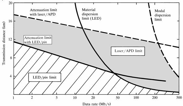
11 Sysem rise-time & Informaion Rae In digial ransmission sysem, he sysem rise-ime limis he bi rae of he sysem according o he following crieria: sys sys < 70% of < 35% of NRZ bi period RZ bi period Example Laser Tx has a rise-ime of 5 ps a 1550 nm and specral widh of 0.1 nm. Lengh of fiber is 60 km wih dispersion ps/(nm.km). The InGaAs APD has a.5 GHz BW. The rise-ime budge (required) of he sysem for NRZ signaling is 0.8 ns whereas he oal rise-ime due o componens is 0.14 ns. (The sysem is designed for 0 Mb/s). Example: Transmission Disance for MM-Fiber NRZ signaling, source/deecor: nm LED/pin or AlGaAs laser/apd combinaions. ; LED oupu=-13 dbm;fiber loss=3.5 db/km;fiber bandwidh 800 MHz.km; q=0.7; 1-dB connecor/coupling loss a each end; 6 db sysem margin, maerial dispersion ins 0.07 ns/(km.nm); specral widh for LED=50 nm. Laser ar 850 nm specral widh=1 nm; laser oupu=0 dbm, Laser sysem margin=8 db;
12
13 Example:Transmission Disance for a SM Fiber Communicaion a 1550 nm, no modal dispersion, Source:Laser; Receiver:InGaAs-APD (11.5 log B dbm) and PIN (11.5log B dbm); Fiber loss =0.3 db/km; D=.5 ps/(km.nm): laser specral widh 1 and 3.5 nm; laser oupu 0 dbm,laser sysem margin=8 db;
14 WDM: WDM is he abbreviaion for Wavelengh Division Muliplexing. Wha i does is o spli he he ligh in an opic fiber ino a number of discree wavelenghs (colors). Each wavelengh (color) is a independen channel running a daa rae a.5gbi/s, 10Gbi/s, 40Gbi/s or even 100Gbi/s (sill under developmen). So if he ligh in he fiber is spli ino 16 wavelenghs (colors or channels), and each wavelengh is running a 40Gbi/s daa rae, we ge a oal of 40Gbi/s x 16 = 640Gbi/s rae. This is especially rue in long haul and ulra long haul fiber opic communicaion links. In addiion, fibers carrying 64 and more channels (wavelenghs) are already available on he marke now. Which means we can run,560gbi/s daa rae on a single fiber. How abou 48 fibers in a single fiber opic cable? Tha gives us an amazing,560gbi/s x 48 = 1,880Gbi/s link. Of course, his kind of high speed and high fiber coun links are usually only deployed for Inerne backbones. From aforemenioned samples, you can see he shocking ruh abou WDM. I dramaically increases capaciy of a fiber opic link while minimizes equipmen and fiber opic cable cos. Wha is DWDM? DWDM sands for Dense Wavelengh Division Muliplexing. Here "dense" means he wavelengh channels are very narrow and close o each oher. For 100 GHz dense WDM, he inerval beween adjacen channels are only 100 GHz, (or 0.8nm). For example, he adjacen channels could be nm, nm and nm. DWDM are widely used for he 1550nm band so as o leverage he capabiliies of EDFA (Erbium Doped Fiber Amplifiers). EDFAs are commonly used for he 155nm ~ 1565nm (C band) and 1570nm ~ 1610nm (L Band).
15 Why is DWM so imporan? The exploiaion of DWDM has fueled an explosion in ransmission capaciy. The amoun of informaion ha can be sen over he fiber cables ha span he world has increased so much ha here is now a glu of available capaciy. In pracice, more can be wrung ou of DWD sysems by exending he upper or lower bounds of he available ransmission window or by spacing wavelenghs more closely, ypically a 50GHz, or even 5 GHz. In doing his, suppliers can double or riple he number of channels. Each opical channel can currenly be rouinely used for ransmission of ligh pulses a 10Gbi/s, or even higher daa raes a 100 GHz spacing. Wih he help of WDM, a pair of fibers can provide daa capaciy of several hundred gigabis per second. WDM echnology does no require any upgrade or replacemen of he fiber infrasrucure ha has been pu in he ground. Hence, we can upgrade links from one capaciy level o he nex simply by reconfiguring or upgrading erminal equipmen and repeaers.
16
17
18
19
20
21
22
23 SONET: Synchronous Opical NETwork Designed for opical ranspor (high birae) Direc mapping of lower levels ino higher ones Carry all PDH ypes in one universal hierarchy ITU version = Synchronous Digial Hierarchy differen erminology bu ineroperable Overhead doesn increase wih rae OAM designed-in from beginning SONET was designed wih definie layering conceps Physical layer opical fiber (linear or ring) when exceed fiber reach regeneraors regeneraors are no mere amplifiers, regeneraors use heir own overhead
24 fiber beween regeneraors called secion (regeneraor secion) Line layer link beween SONET muxes (Add/Drop Muliplexers) inpu and oupu a his level are Virual Tribuaries (VCs) acually layers lower order VC (for low birae payloads) higher order VC (for high birae payloads) Pah layer end-o-end pah of clien daa (ribuaries) clien daa (payload) may be PDH ATM packe daa A SONET signal is called a Synchronous Transpor Signal The basic STS is STS-1, all ohers are muliples of i - STS-N The (opical) physical layer signal corresponding o an STS-N is an OC-N SONET Opical rae STS-1 OC M STS-3 OC M STS-1 OC M STS-48 OC M STS-19 OC M
Chapter 8. Digital Links
 Chapter 8 Digital Links Point-to-point Links Link Power Budget Rise-time Budget Power Penalties Dispersions Noise Content Photonic Digital Link Analysis & Design Point-to-Point Link Requirement: - Data
Lecture 11. Digital Transmission Fundamentals
 CS4/MSc Compuer Neworking Lecure 11 Digial Transmission Fundamenals Compuer Neworking, Copyrigh Universiy of Edinburgh 2005 Digial Transmission Fundamenals Neworks consruced ou of Links or ransmission
Optical Short Pulse Generation and Measurement Based on Fiber Polarization Effects
 Opical Shor Pulse Generaion and Measuremen Based on Fiber Polarizaion Effecs Changyuan Yu Deparmen of Elecrical & Compuer Engineering, Naional Universiy of Singapore, Singapore, 117576 A*STAR Insiue for
Lecture 4. EITN Chapter 12, 13 Modulation and diversity. Antenna noise is usually given as a noise temperature!
 Lecure 4 EITN75 2018 Chaper 12, 13 Modulaion and diversiy Receiver noise: repeiion Anenna noise is usually given as a noise emperaure! Noise facors or noise figures of differen sysem componens are deermined
Optical Digital Transmission Systems. Xavier Fernando ADROIT Lab Ryerson University
 Optical Digital Transmission Systems Xavier Fernando ADROIT Lab Ryerson University Overview In this section we cover point-to-point digital transmission link design issues (Ch8): Link power budget calculations
Wrap Up. Fourier Transform Sampling, Modulation, Filtering Noise and the Digital Abstraction Binary signaling model and Shannon Capacity
 Wrap Up Fourier ransorm Sampling, Modulaion, Filering Noise and he Digial Absracion Binary signaling model and Shannon Capaciy Copyrigh 27 by M.H. Perro All righs reserved. M.H. Perro 27 Wrap Up, Slide
EXPERIMENT #9 FIBER OPTIC COMMUNICATIONS LINK
 EXPERIMENT #9 FIBER OPTIC COMMUNICATIONS LINK INTRODUCTION: Much of daa communicaions is concerned wih sending digial informaion hrough sysems ha normally only pass analog signals. A elephone line is such
Examination Mobile & Wireless Networking ( ) April 12,
 April 12,") Page 1 of 5 Examinaion Mobile & Wireless Neworking (192620010) April 12, 2017 13.45 16.45 Noes: Only he overhead shees used in he course, 2 double-sided shees of noes (any fon size/densiy!), and a dicionary
Page 1 of 5 Examinaion Mobile & Wireless Neworking (192620010) April 12, 2017 13.45 16.45 Noes: Only he overhead shees used in he course, 2 double-sided shees of noes (any fon size/densiy!), and a dicionary
Chapter 2. The Physical Layer
 Chaper 2 The Physical Layer The Physical Layer Defines he mechanical, elecrical and iming inerfaces o he nework Transmission media - guided (copper and fiber opics) - wireless (radio erresrial) - saellie
Communication Systems. Communication Systems
 Communicaion Sysems Analog communicaion Transmi and receive analog waveforms Ampliude Modulaion (AM Phase Modulaion (PM Freq. Modulaion (FM Quadraure Ampliude Modulaion (QAM Pulse Ampliude Modulaion (PAM
Digital Communications - Overview
 EE573 : Advanced Digial Communicaions Digial Communicaions - Overview Lecurer: Assoc. Prof. Dr Noor M Khan Deparmen of Elecronic Engineering, Muhammad Ali Jinnah Universiy, Islamabad Campus, Islamabad,
Industrial, High Repetition Rate Picosecond Laser
 RAPID Indusrial, High Repeiion Rae Picosecond Laser High Power: RAPID is a very cos efficien, compac, diode pumped Nd:YVO4 picosecond laser wih 2 W average power a 1064 nm. Is 10 ps-pulses have high pulse
ICT 5305 Mobile Communications
 ICT 5305 Mobile Communicaions Lecure - 2 April 2016 Dr. Hossen Asiful Musafa 2.1 Frequencies for communicaion VLF = Very Low Frequency LF = Low Frequency MF = Medium Frequency HF = High Frequency VHF =
Investigation and Simulation Model Results of High Density Wireless Power Harvesting and Transfer Method
 Invesigaion and Simulaion Model Resuls of High Densiy Wireless Power Harvesing and Transfer Mehod Jaber A. Abu Qahouq, Senior Member, IEEE, and Zhigang Dang The Universiy of Alabama Deparmen of Elecrical
Problem Sheet: Communication Channels Communication Systems
 Problem Shee: Communicaion Channels Communicaion Sysems Professor A. Manikas Chair of Communicaions and Array Processing Deparmen of Elecrical & Elecronic Engineering Imperial College London v.11 Communicaion
Chapter 14: Bandpass Digital Transmission. A. Bruce Carlson Paul B. Crilly 2010 The McGraw-Hill Companies
 Communicaion Sysems, 5e Chaper 4: Bandpass Digial Transmission A. Bruce Carlson Paul B. Crilly The McGraw-Hill Companies Chaper 4: Bandpass Digial Transmission Digial CW modulaion Coheren binary sysems
Signal Characteristics
 Signal Characerisics Analog Signals Analog signals are always coninuous (here are no ime gaps). The signal is of infinie resoluion. Discree Time Signals SignalCharacerisics.docx 8/28/08 10:41 AM Page 1
Passband Data Transmission I References Phase-shift keying Chapter , S. Haykin, Communication Systems, Wiley. G.1
 Passand Daa ransmission I References Phase-shif keying Chaper 4.-4.3, S. Haykin, Communicaion Sysems, Wiley. G. Inroducion Inroducion In aseand pulse ransmission, a daa sream represened in he form of a
Analog/Digital Communications Primer
 for Amaeur Radio Virginia Polyechnic Insiue & Sae Universiy March 19, 2013 # include //... in main() { floa kf = 0.1f; // modulaion facor liquid_freqdem_ype ype = LIQUID_FREQDEM_DELAYCONJ;
TELE4652 Mobile and Satellite Communications
 TELE465 Mobile and Saellie Communicaions Assignmen (Due: 4pm, Monday 7 h Ocober) To be submied o he lecurer before he beginning of he final lecure o be held a his ime.. This quesion considers Minimum Shif
UNIT IV DIGITAL MODULATION SCHEME
 UNI IV DIGIAL MODULAION SCHEME Geomeric Represenaion of Signals Ojecive: o represen any se of M energy signals {s i (} as linear cominaions of N orhogonal asis funcions, where N M Real value energy signals
EECS 380: Wireless Communications Weeks 5-6
 EECS 380: Wireless Communicaions Weeks 5-6 Michael L. Honig Norhwesern Universiy April 2018 1 Why Digial Communicaions? 1G (analog) à 2G (digial) à 3G (digial) Digiized voice requires abou 64 kbps, herefore
Optical phase locked loop for transparent inter-satellite communications
 Opical phase locked loop for ransparen iner-saellie communicaions F. Herzog 1, K. Kudielka 2,D.Erni 1 and W. Bächold 1 1 Communicaion Phoonics Group, Laboraory for Elecromagneic Fields and Microwave Elecronics,
IR Receiver Module for Light Barrier Systems
 New Produc IR Receiver Module for Ligh Barrier Sysems TSSP5838 1926 FEATURES Low supply curren Phoo deecor and preamplifier in one package Inernal filer for 38 khz IR signals Shielding agains EMI Supply
Generating Polar Modulation with R&S SMU200A
 Rohde & Schwarz producs: SMU00 Generaing Polar Modulaion wih R&S SMU00 Polar modulaion is a mehod where digial modulaion is realized as a combinaion of phase and ampliude modulaion, raher han using an
Dimensions. Model Number. Electrical connection emitter. Features. Electrical connection receiver. Product information. Indicators/operating means
 OBE-R-SE Dimensions.8.8 ø..75 7.5 6. 5 6.7 4.9 4. 5.9 ø.6 Model Number OBE-R-SE Elecrical connecion emier Thru-beam sensor wih m fixed cable Feaures 45 cable oule for maximum mouning freedom under exremely
Principles of Communications
 Sae Key Lab. on ISN, Xidian Universiy Principles of Communicaions Chaper VI: Elemenary Digial Modulaion Sysem Email: ychwang@mail.xidian.edu.cn Xidian Universiy Sae Key Lab. on ISN December 13, 2013 Sae
EE558 - Digital Communications
 EE558 - Digial Communicaions Lecure 1: Inroducion & Overview Dr. Duy Nguyen Ouline 1 Course Informaion 2 Inroducion o Digial Communicaions Course Informaion 2 Adminisraion Hours and Locaion Lecures: TTH
OFDMA for Access Networks: Optical Setup
 OFDMA or Access Neworks: Opical Seup Johannes von Hoyningen-Huene Lehrsuhl ür Nachrichen- und Überragungsechnik CAU Kiel Workshop der ITG-Fachgruppe 5.3.1 Kiel, 10.2.2015 Moivaion or OFDMA in Opical Access
ECS455: Chapter 4 Multiple Access
 Spread specrum (SS) ECS455: Chaper 4 Muliple Access Dr.Prapun Suksompong prapun.com/ecs455 4.3 DS/SS Oice Hours: BKD, 6h loor o Sirindhralai building Tuesday 4:20-5:20 Wednesday 4:20-5:20 Friday 9:5-0:5
A Harmonic Circulation Current Reduction Method for Parallel Operation of UPS with a Three-Phase PWM Inverter
 160 Journal of Power Elecronics, Vol. 5, No. 2, April 2005 JPE 5-2-9 A Harmonic Circulaion Curren Reducion Mehod for Parallel Operaion of U wih a Three-Phase Inverer Kyung-Hwan Kim, Wook-Dong Kim * and
Passband Data Transmission II References Frequency-shift keying Chapter 6.5, S. Haykin, Communication Systems, Wiley. H.1
 Passand Daa ransmission II Reerences Frequency-shi keying Chaper 6.5, S. Haykin, Communicaion Sysems, Wiley. H. Inroducion Inroducion PSK and QAM are linear modulaion FSK is a nonlinear modulaion Similar
P. Bruschi: Project guidelines PSM Project guidelines.
 Projec guidelines. 1. Rules for he execuion of he projecs Projecs are opional. Their aim is o improve he sudens knowledge of he basic full-cusom design flow. The final score of he exam is no affeced by
Diodes. Diodes, Page 1
 Diodes, Page 1 Diodes V-I Characerisics signal diode Measure he volage-curren characerisic of a sandard signal diode, he 1N914, using he circui shown below. The purpose of he back-o-back power supplies
Chapter 2 Summary: Continuous-Wave Modulation. Belkacem Derras
 ECEN 44 Communicaion Theory Chaper Summary: Coninuous-Wave Modulaion.1 Modulaion Modulaion is a process in which a parameer of a carrier waveform is varied in accordance wih a given message (baseband)
FROM ANALOG TO DIGITAL
 FROM ANALOG TO DIGITAL OBJECTIVES The objecives of his lecure are o: Inroduce sampling, he Nyquis Limi (Shannon s Sampling Theorem) and represenaion of signals in he frequency domain Inroduce basic conceps
4 20mA Interface-IC AM462 for industrial µ-processor applications
 Because of he grea number of indusrial buses now available he majoriy of indusrial measuremen echnology applicaions sill calls for he sandard analog curren nework. The reason for his lies in he fac ha
ECMA st Edition / June Near Field Communication Wired Interface (NFC-WI)
") ECMA-373 1 s Ediion / June 2006 Near Field Communicaion Wired Inerface (NFC-WI) Sandard ECMA-373 1 s Ediion / June 2006 Near Field Communicaion Wired Inerface (NFC-WI) Ecma Inernaional Rue du Rhône 114
ECMA-373 1 s Ediion / June 2006 Near Field Communicaion Wired Inerface (NFC-WI) Sandard ECMA-373 1 s Ediion / June 2006 Near Field Communicaion Wired Inerface (NFC-WI) Ecma Inernaional Rue du Rhône 114
Mach Zehnder Interferometer for Wavelength Division Multiplexing
 Mach Zehnder nerferomeer for Wavelengh Division Muliplexing Ary Syahriar Pusa Pengkajian dan Penerapan Teknologi nformasi dan Elekronika Badan Pengkajian dan Penerapan Teknologi e-mail : ary@inn.bpp.go.id
IR Receiver Module for Light Barrier Systems
 IR Receiver Module for Ligh Barrier Sysems DESIGN SUPPORT TOOLS 19026 click logo o ge sared FEATURES Up o 2 m for presence sensing Uses modulaed burss a 38 khz 940 nm peak wavelengh PIN diode and sensor
Chapter 4: Angle Modulation
 Tes 2 Review Tes 2 Review Professor Deepa Kundur Universiy of Torono Reference: Secions: 4.1, 4.2, 4.3, 4.4, 4.6, 4.7, 4.8 of 5.1, 5.2, 5.3, 5.4, 5.5 6.1, 6.2, 6.3, 6.4, 6.5, 6.6 S. Haykin and M. Moher,
Chapter 4: Angle Modulation
 Tes 2 Review Tes 2 Review Professor Deepa Kundur Universiy of Torono Reference: Secions: 4.1, 4.2, 4.3, 4.4, 4.6, 4.7, 4.8 of 5.1, 5.2, 5.3, 5.4, 5.5 6.1, 6.2, 6.3, 6.4, 6.5, 6.6 S. Haykin and M. Moher,
IR Receiver Modules for Remote Control Systems
 IR Receiver Modules for Remoe Conrol Sysems FEATURES Very low supply curren Phoo deecor and preamplifier in one package Inernal filer for PCM frequency Improved shielding agains EMI Supply volage: 2.5
L A-B-C dei Segnali Spread-Spectrum
 L A-B-C dei Segnali Spread-Specrum Marco Luise Universiy of Pisa, Ialy Diparimeno Ingegneria dell Informazione hp://www.ie.unipi.i/m.luise PAM Signal +A -A s() a 0 a 1 a 2 a 3 a 4 {a k }=+1 Binary Symbols
IR Receiver Module for Light Barrier Systems
 IR Receiver Module for Ligh Barrier Sysems TSSP4..SSXB Vishay Semiconducors DESIGN SUPPORT TOOLS Models Available 3 MECHANICAL DATA Pinning: = OUT, = GND, 3 = V S 7 click logo o ge sared DESCRIPTION The
IR Receiver Modules for Remote Control Systems
 MECHANICAL DATA 2 Pinning for TSOP348.., TSOP344..: = OUT, 2 = GND, 3 = V S Pinning for TSOP322.., TSOP324..: = OUT, 2 = V S, 3 = GND 3 6672 FEATURES Very low supply curren Phoo deecor and preamplifier
Mobile Communications Chapter 2: Wireless Transmission
 This book ocuses on higher layer aspecs o mobile communicaions, he compuer science elemens raher han on he radio and ransmission aspecs, he elecrical engineering par. This chaper inroduces only hose undamenal
IR Receiver Modules for Remote Control Systems
 IR Receiver Modules for Remoe Conrol Sysems FEATURES Improved immuniy agains HF and RF noise Low supply curren Phoo deecor and preamplifier in one package Inernal filer for PCM frequency Supply volage:
IR Sensor Module for Reflective Sensor, Light Barrier, and Fast Proximity Applications
 IR Sensor Module for Reflecive Sensor, Ligh Barrier, and Fas Proximiy Applicaions 2 3 DESIGN SUPPORT TOOLS Models Available MECHANICAL DATA Pinning: = OUT, 2 = GND, 3 = V S click logo o ge sared 6672 APPLICATIONS
IR Receiver Modules for Remote Control Systems
 IR Receiver Modules for Remoe Conrol Sysems MECHANICAL DATA Pinning for : 1 = OUT, 2 = GND, 3 = V S 1926 FEATURES Very low supply curren Phoo deecor and preamplifier in one package Opimized for Sony and
IR Receiver Modules for Remote Control Systems
 IR Receiver Modules for Remoe Conrol Sysems 2 MECHNICAL DATA Pinning for TSOP348.., TSOP344..: = OUT, 2 = GND, 3 = V S Pinning for TSOP322.., TSOP324..: = OUT, 2 = V S, 3 = GND 3 6672 FEATURES Very low
Communications II Lecture 7: Performance of digital modulation
 Communicaions II Lecure 7: Performance of digial modulaion Professor Kin K. Leung EEE and Compuing Deparmens Imperial College London Copyrigh reserved Ouline Digial modulaion and demodulaion Error probabiliy
Dimensions. Transmitter Receiver ø2.6. Electrical connection. Transmitter +UB 0 V. Emitter selection. = Light on = Dark on
 OBE-R-SE Dimensions Transmier.. 7.5 9..5.8 4.9 4 5 M 8.9 7.5 9..5.8 4 5 M 8.9 ø.6 ø.6 Model Number OBE-R-SE Thru-beam sensor wih m fixed cable Elecrical connecion Transmier Feaures BN +UB WH IN Ulra-small
IR Receiver Modules for Remote Control Systems
 IR Receiver Modules for Remoe Conrol Sysems 2 MECHNICAL DATA Pinning for TSOP44.., TSOP48..: = OUT, 2 = GND, 3 = V S Pinning for TSOP22.., TSOP24..: = OUT, 2 = V S, 3 = GND 3 6672 FEATURES Low supply curren
Pulse Train Controlled PCCM Buck-Boost Converter Ming Qina, Fangfang Lib
 5h Inernaional Conference on Environmen, Maerials, Chemisry and Power Elecronics (EMCPE 016 Pulse Train Conrolled PCCM Buck-Boos Converer Ming Qina, Fangfang ib School of Elecrical Engineering, Zhengzhou
f t 2cos 2 Modulator Figure 21: DSB-SC modulation.
 4.5 Ampliude modulaion: AM 4.55. DSB-SC ampliude modulaion (which is summarized in Figure 21) is easy o undersand and analyze in boh ime and frequency domains. However, analyical simpliciy is no always
Dimensions. Transmitter Receiver ø2.6. Electrical connection. Transmitter +UB 0 V. Emitter selection. = Light on = Dark on
 OBE-R-SE Dimensions Transmier.. 7.5 9..5.8 4.9 4 5 M 8.9 7.5 9..5.8 4 5 M 8.9 ø.6 ø.6 Model Number OBE-R-SE Thru-beam sensor wih m fixed cable Elecrical connecion Transmier Feaures BN +UB WH IN Ulra-small
Channel Estimation for Wired MIMO Communication Systems
 Channel Esimaion for Wired MIMO Communicaion Sysems Final Repor Mulidimensional DSP Projec, Spring 2005 Daifeng Wang Absrac This repor addresses raining-based channel modeling and esimaion for a wired
DISCONTINUED MODEL Replaced with Model JPS3
 Plug-in Signal Condiioners M-UNIT PUSE ADDER (field-programmable) MODE MODE & SUFFIX CODE SEECTI MODE A : Dry conac B :Volage pulse (Specify sensiiviy) C : V pulse (sensiiviy V) D : V/V pulse (sensiiviy
IR Sensor Module for Reflective Sensor, Light Barrier, and Fast Proximity Applications
 IR Sensor Module for Reflecive Sensor, Ligh Barrier, and Fas Proximiy Applicaions 2 3 DESIGN SUPPORT TOOLS 6672 click logo o ge sared FEATURES Up o 2 m for presence and proximiy sensing Uses modulaed burss
IR Receiver Modules for Remote Control Systems
 TSOP32.., TSOP34.. IR Receiver Modules for Remoe 2 3 MECHANICAL DATA Pinning: = GND, 2 = V S, 3 = OUT 94 869 FEATURES Very low supply curren Phoo deecor and preamplifier in one package Inernal filer for
IR Receiver Modules for Remote Control Systems
 IR Receiver Modules for Remoe Conrol Sysems MECHANICAL DATA Pinning for TSOP582.., TSOP584..: 1 = OUT, 2 = GND, 3 = V S Pinning for TSOP592.., TSOP594..: 1 = OUT, 2 = V S, 3 = GND 1926 FEATURES Low supply
Extending the Reach of Short-Reach Optical Interconnects with DSP-Free Direct-Detection
 his aricle has been acceped for publicaion in a fuure issue of his journal, bu has no been fully edied. Conen may change prior o final publicaion. Ciaion informaion: DOI.9/JL.., Journal of Exending he
IR Receiver Modules for Remote Control Systems
 IR Receiver Modules for Remoe Conrol Sysems 2 MECHNICAL DATA Pinning for TSOP44.., TSOP48..: = OUT, 2 = GND, 3 = V S Pinning for TSOP22.., TSOP24..: = OUT, 2 = V S, 3 = GND 3 6672 FEATURES Improved immuniy
IR Receiver Modules for Remote Control Systems
 IR Receiver Modules for Remoe Conrol Sysems FEATURES Very low supply curren Phoo deecor and preamplifier in one package Inernal filer for PCM frequency Supply volage: 2.5 V o 5.5 V Improved immuniy agains
EXPERIMENT #4 AM MODULATOR AND POWER AMPLIFIER
 EXPERIMENT #4 AM MODULATOR AND POWER AMPLIFIER INTRODUCTION: Being able o ransmi a radio frequency carrier across space is of no use unless we can place informaion or inelligence upon i. This las ransmier
DATA SHEET. 1N914; 1N916 High-speed diodes DISCRETE SEMICONDUCTORS Sep 03
 DISCRETE SEMICONDUCTORS DATA SHEET M3D176 Supersedes daa of April 1996 File under Discree Semiconducors, SC01 1996 Sep 03 FEATURES Hermeically sealed leaded glass SOD27 (DO-35) package High swiching speed:
Analog Baseband Communication Systems. Digital Baseband Communication Systems
 EE 421: Communicaions I Dr. Mohammed Hawa Inroducion o Digial Baseband Communicaion Sysems For more informaion: read Chapers 1, 6 and 7 in your exbook or visi hp://wikipedia.org/. Remember ha communicaion
SF2-LP11x Small Form Factor Optical Fiber Transceiver 3.3 Volt, LVPECL, 1300nm LED for Multimode Optical Fiber at up to 200 MBaud
 SF2-LP11x Small Form Facor Fiber Transceiver 3.3 ol,, 13nm LED for Mulimode ORDERING INFORMATION Applicaion Fas Eherne ESON ATM Fas Eherne ESON ATM BLOK DIAGRAM SD RX+ RX- TX- TX+ PEL DRIER PEL BUFFER
IR Receiver Modules for Remote Control Systems
 IR Receiver Modules for Remoe Conrol Sysems MECHANICAL DATA Pinning for : 1 = OUT, 2 = GND, 3 = V S 1926 FEATURES Improved immuniy agains HF and RF noise Low supply curren Phoo deecor and preamplifier
Simulation Series Termination
 ESE370: Circui-Level Modeling, Design, and Opimizaion for Digial Sysems Day 35: December 5, 2012 Transmission Lines Implicaions 1 Transmission Line Agenda Where arise? General wire formulaion Lossless
When answering the following 25 questions, always remember that there is someone who has to grade them. So please use legible handwriting.
 38963, VU Mobile Kommunikaion Miderm Exam: Insiu für Nachrichenechnik und Hochfrequenzechnik When answering he following 5 quesions, always remember ha here is someone who has o grade hem So please use
Chapter 2 Introduction: From Phase-Locked Loop to Costas Loop
 Chaper 2 Inroducion: From Phase-Locked Loop o Cosas Loop The Cosas loop can be considered an exended version of he phase-locked loop (PLL). The PLL has been invened in 932 by French engineer Henri de Belleszice
IR Receiver Modules for Remote Control Systems
 IR Receiver Modules for Remoe Conrol Sysems 1926 FEATURES Very low supply curren Phoo deecor and preamplifier in one package Inernal filer for PCM frequency Supply volage: 2.5 V o 5.5 V Improved immuniy
CHAPTER CONTENTS. Notes. 9.0 Line Coding. 9.1 Binary Line Codes
 Noes CHAPTER CONTENTS 9. Line Coding 9. inary Line Codes 9. ipolar and iphase Line Codes 9.. AMI 9... inary N Zero Subsiuion 9..3 lock Line Codes 9.3 M-ary Correlaion Codes 9.3. Q 9.3. Correlaion Coding
IR Receiver Modules for Remote Control Systems
 TSOP.., TSOP4.., TSOP6.., TSOP4.., TSOP44.., TSOP46.. IR Receiver Modules for Remoe Conrol Sysems MECHANICAL DATA Pinning for TSOP4...: = OUT, = GND, = V S Pinning for TSOP...: = OUT, = V S, = GND 667
MODEL: M6SXF1. POWER INPUT DC Power R: 24 V DC
 Tension-Clamp Ulra-Slim Signal Condiioners M6S Series FUNCTION MODULE (PC programmable) Funcions & Feaures Mainenance-free ension clamp connecion Single inpu filer and funcion module 12 ypes of funcions
Negative frequency communication
 Negaive frequency communicaion Fanping DU Email: dufanping@homail.com Qing Huo Liu arxiv:2.43v5 [cs.it] 26 Sep 2 Deparmen of Elecrical and Compuer Engineering Duke Universiy Email: Qing.Liu@duke.edu Absrac
Introduction: Analog Communication: Goal: Transmit a message from one location to another.
 ECE-5 Phil Schnier January 6, 8 Inroducion: Goal: Transmi a rom one locaion o anoher When is coninuous waveorm analog comm (eg, FM radio), sequence o numbers digial comm (eg, mp ile), hough he sequence
Experimental demonstration of 10 Gb/s multilevel carrier-less amplitude and phase modulation for short range optical communication systems
 Experimenal demonsraion of 1 Gb/s mulilevel carrier-less ampliude and phase modulaion for shor range opical communicaion sysems Li Tao, 1,2 Yiguang Wang, 1 Yuliang Gao, 3 Alan Pak Tao Lau, 3 Nan Chi, 1,*
Performance Analysis of High-Rate Full-Diversity Space Time Frequency/Space Frequency Codes for Multiuser MIMO-OFDM
 Performance Analysis of High-Rae Full-Diversiy Space Time Frequency/Space Frequency Codes for Muliuser MIMO-OFDM R. SHELIM, M.A. MATIN AND A.U.ALAM Deparmen of Elecrical Engineering and Compuer Science
Communications II Lecture 5: Effects of Noise on FM. Professor Kin K. Leung EEE and Computing Departments Imperial College London Copyright reserved
 Communicaions II Lecure 5: Eecs o Noise on FM Proessor Kin K. Leung EEE and Compuing Deparmens Imperial College London Copyrigh reserved Ouline Recap o FM FM sysem model in noise Derivaion o oupu SNR Pre/de-emphasis
Memorandum on Impulse Winding Tester
 Memorandum on Impulse Winding Teser. Esimaion of Inducance by Impulse Response When he volage response is observed afer connecing an elecric charge sored up in he capaciy C o he coil L (including he inside
ECMA-373. Near Field Communication Wired Interface (NFC-WI) 2 nd Edition / June Reference number ECMA-123:2009
 2 nd Edition / June Reference number ECMA-123:2009") ECMA-373 2 nd Ediion / June 2012 Near Field Communicaion Wired Inerface (NFC-WI) Reference number ECMA-123:2009 Ecma Inernaional 2009 COPYRIGHT PROTECTED DOCUMENT Ecma Inernaional 2012 Conens Page 1 Scope...
ECMA-373 2 nd Ediion / June 2012 Near Field Communicaion Wired Inerface (NFC-WI) Reference number ECMA-123:2009 Ecma Inernaional 2009 COPYRIGHT PROTECTED DOCUMENT Ecma Inernaional 2012 Conens Page 1 Scope...
IR Receiver Modules for Remote Control Systems
 IR Receiver Modules for New TSOP48.. 2 3 MECHANICAL DATA Pinning = OUT, 2 =, 3 = 6672 FEATURES Low supply curren Phoo deecor and preamplifier in one package Inernal filer for PCM frequency Improved shielding
General data 8/91. Overview
 SIRIUS 3RS0, 3RS, 3RS0, 3RS Temperaure Monioring Relays General daa Overview Temperaure seing LED "Device on volage" LED "Relay swiched" Hyseresis swich NSB0_04a LED for display "Up and Down" keys Roary
EE 330 Lecture 24. Amplification with Transistor Circuits Small Signal Modelling
 EE 330 Lecure 24 Amplificaion wih Transisor Circuis Small Signal Modelling Review from las ime Area Comparison beween BJT and MOSFET BJT Area = 3600 l 2 n-channel MOSFET Area = 168 l 2 Area Raio = 21:1
Explanation of Maximum Ratings and Characteristics for Thyristors
 8 Explanaion of Maximum Raings and Characerisics for Thyrisors Inroducion Daa shees for s and riacs give vial informaion regarding maximum raings and characerisics of hyrisors. If he maximum raings of
Optical fibres. Optical fibres made from high-density glass can carry light signals long distances without losing any light through their sides.
 Nearly here Nailed i! Uni 1 Conen Opical fibres Opical fibres made from high-densiy glass can carry ligh signals long disances wihou losing any ligh hrough heir sides. Criical angle The criical angle,
4.5 Biasing in BJT Amplifier Circuits
 4/5/011 secion 4_5 Biasing in MOS Amplifier Circuis 1/ 4.5 Biasing in BJT Amplifier Circuis eading Assignmen: 8086 Now le s examine how we C bias MOSFETs amplifiers! f we don bias properly, disorion can
A WIDEBAND RADIO CHANNEL MODEL FOR SIMULATION OF CHAOTIC COMMUNICATION SYSTEMS
 A WIDEBAND RADIO CHANNEL MODEL FOR SIMULATION OF CHAOTIC COMMUNICATION SYSTEMS Kalle Rui, Mauri Honanen, Michael Hall, Timo Korhonen, Veio Porra Insiue of Radio Communicaions, Helsini Universiy of Technology
Investigation of Novel Ultrasonic Positioning Method Installed in Sensor Network
 PIERS ONLINE, VOL. 5, NO. 4, 2009 321 Invesigaion of Novel Ulrasonic Posiioning Mehod Insalled in Sensor Nework Misuaka Hikia, Yasushi Hiraizumi, Hiroaki Aoki, Junji Masuda, and Tomoaki Waanabe Faculy
IR Receiver Modules for Remote Control Systems
 2 3 MECHANICAL DATA Pinning: = OUT, 2 =, 3 = V S 6672 FEATURES Very low supply curren Phoo deecor and preamplifier in one package Inernal filer for PCM frequency Improved shielding agains EMI Supply volage:
Sensing, Computing, Actuating
 Sensing, Compuing, Acuaing Sander Suik (s.suik@ue.nl) Deparmen of Elecrical Engineering Elecronic Sysems INDUCTIE SENSOS (Chaper.5,.6,.0, 5.4) 3 Inducive sensors damping conrol wheel speed sensor (ABS)
Laser retro-reflective photoelectric sensor with polarisation filter. Dimensioned drawing
 Specificaions and descripion PRKL 3B Laser rero-reflecive phooelecric sensor wih polarisaion filer Dimensioned drawing en 08-2011/04 50105363 2 khz 0 3m 10-30 V DC Polarized rero-reflecive phooelecric
ESD. What is ESD? Lightning to the buildings. ESD to IC s. ESD protection circuit for IC s. Lightning Rod for Buildings
 007/Dec/9 Wha is ESD? ESD ElecroSaic Discharge ESD is a high-curren (~mps) and shor-duraion ime (~ns) even ESD even due o ribo-elecrically generaed charges. ESD o IC s Lighning o he buildings ESD proecion
Laser retro-reflective photoelectric sensor with polarization filter. Dimensioned drawing
 Specificaions and descripion PRKL 3B Laser rero-reflecive phooelecric sensor wih polarizaion filer Dimensioned drawing en 09-2012/06 50105363 2 khz 0 3m 10-30 V DC We reserve he righ o make changes DS_PRKL3B622_en_50105363.fm
The design of an improved matched filter in DSSS-GMSK system
 Journal of Physics: Conference Series PAPER OPEN ACCESS The design of an improved mached filer in DSSS-GMSK sysem To cie his aricle: Mao Wei-ong e al 16 J. Phys.: Conf. Ser. 679 1 View he aricle online
Wavelength Multiplexing. The Target
 The Target Design a MAN* like fiber network for high data transmission rates. The network is partial below sea level and difficult to install and to maintain. Such a fiber network demands an optimized
MODEL: M6NXF1. POWER INPUT DC Power R: 24 V DC
 Screw Terminal Ulra-Slim Signal Condiioners M6N Series FUNCTION MODULE (PC programmable) Funcions & Feaures Single inpu filer and funcion module 12 ypes of funcions are PC programmable 7.5-mm wide ulra-slim