Instructor: Doc. Ivan Kassamakov, Assistant: Kalle Hanhijärvi, Doctoral student
|
|
|
- Morris Shields
- 5 years ago
- Views:
Transcription


1 Instructor: Doc. Ivan Kassamakov, Assistant: Kalle Hanhijärvi, Doctoral student Course webpage:
2 Gaussian Optics Errors Taylor series 3 θ sin θ = θ θ cosθ = Aberration IA Transverse Aberration IB-Longitudinal Aberration Ideal Wavefront Ideal rays Optical System Actual Rays B I A Blur Actual Wavefront Paraxial Image Plane
3 Any deviation from perfection of an image not due to diffraction are known as aberrations There are six primary aberrations: Chromatic aberrations Longitudinal chr. Ab. Lateral chr. Ab Wavefront aberrations Spherical aberration Astigmatism Coma Optical Aberrations Curvature of field Distortion All, except the first one, affect both refractive and reflective components. Chromatic aberration affects only refractive components.
4 Wavefront Aberrations Aberrated Ideal wavefront in the pupil
5 Spherical Aberration D-aperture (Entrance Pupil) Size Longitudinal SA~D 2 LSA Transverse SA~D 3 TSA D Ideal (parabolic) surfaces Marginal Focal Plane Need to reduce D limit the amount of light Paraxial Focal Plane For lenses and mirrors made with spherical surfaces, rays which are parallel to the optic axis but at different distances from the center fail to converge to the same point. Effect is usually a 1%, or larger, difference in focal length For mirrors, effect can be totally removed if the mirror is parabolic instead of spherical (However, it is difficult to grind parabolic shape!)
6 Spherical Aberration Correction 1. Aspherical Optics 2. Combination of Lenses n 1 n 2 n 1 n 2 Aplanat Positive Lens Positive Spherical Aberration Negative Lens Negative Spherical Aberration

7 Spherical Aberration With SA SA free

8 Coma This aberration exists for the off-axis points Chief ray I O O Marginal Rays Chief Ray Focus I Marginal Rays Focus The optical powers are different for chief and marginal rays Create trailing "comet-like" blur directed away from axis. May produce a sharp image in the center of the field, but become increasingly blurred toward the edges.

9 Demonstration of Coma Aberration Circular stars Comet-shaped stars


10 Astigmatism Tangential rays Tangential Focus Chief Ray Sagital Focus Sagital Rays Circle of Minimum Confusion Optical Powers are different for Tangential and Sagital Rays The lens corrected for spherical aberration and coma is called aplanat If it is also corrected for astigmatism it is called anastigmat

11 Distortion Unlike other aberrations the distortion changes the shape of image and not its sharpness O I s o Object Put Aperture Stop behind the lens AS For points far from axis the AS lets through only the rays that have smaller distance from the lens hence these objects experience higher magnification Image Image Pin-Cushion Distortion

12 Distortion Consider another type of distortion O s o I Object AS Put Aperture Stop in front of the lens For points far from axis the AS lets through only the rays that have larger distance from the lens hence these objects experience lower magnification Image Image Barrel Distortion


13 Correcting Radial Lens Distortions Before After These distortions are fixed by an orthoscopic doublet or a Zeiss orthometer.


14 Field Curvature O O θ ' s 0 s 0 The focal plane is not a plane, but a curved surface of radius f ' s i s i f I I Rays at a large angle see the lens as having an effectively smaller diameter and an effectively smaller focal length, forming the image of the off axis points closer to the lens.

15 Chromatic aberration Because the lens material has a different refractive index for each wavelength, the lens will have a different focal length for each wavelength. Recall the lens-maker s formula: 1/ f( λ) = ( n( λ) 1)(1/ R 1/ R ) 1 2 You can model spherical aberration using ray tracing, but only one color at a time.
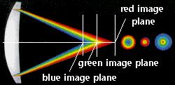
16 Chromatic aberration

17 Chromatic Aberration f λ The refractive index is larger for blue than red, so the focal length is less for blue than red.
18 Chromatic Aberration Longitudinal Chromatic Aberration Lensmaker Equation F F F C = ( nc 1) + fc R R = ( nf 1) + > ff R1 R2 f C Lateral Chromatic Aberration


19 Chromatic Aberrations longitudinal chromatic aberration (axial) transverse chromatic aberration (lateral)


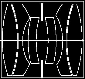
20 Chromatic aberration greatly reduced (~10 times) by multiple lens system, e.g. achromatic doublet Low dispersion glass High dispersion glass Usually, two lens have same curvature and are cemented together Note: Same focal length for two wavelengths so that they can be corrected simultaneously
21 Spherical Coma Astigmatism Distortion Summary of aberrations Mono-chromatic (affects single wavelength light), on- and off-axis Mono-chromatic, off-axis only Mono-chromatic, off-axis only Mono-chromatic, off-axis only Field Curvature Mono-chromatic, off-axis only Chromatic Hetero-chromatic (affect multiple wavelength light), on- and off- axis Corrections: Most of the aberrations can be reduced (but never totally removed) by using multi-lens system.

22 Telescopes
23 Optical Telescope Telescopes serves three main functions: (1) they are light collectors. The simplest telescopes simply focus light rays to a small area.; (2) Resolve light so that finer details can be seen; (3) Magnification: making objects look bigger (closer) As we are observing objects at very large distances, light can be assumed to come from infinity and can be represented as parallel rays Two main types: refractive and reflective

24 The Powers of a Telescope: Size Does Matter 1. Light-gathering power: Depends on the surface area A of the primary lens / mirror, proportional to diameter squared: D A = π (D/2) 2


25 The Powers of a Telescope 2. Resolving power: Wave nature of light => The telescope aperture produces fringe rings that set a limit to the resolution of the telescope. Resolving power = minimum angular distance α min between two objects that can be separated. α min = 1.22 (λ/d) For optical wavelengths, this gives α min α min = 11.6 arcsec / D[cm]
26 The Powers of a Telescope 3. Magnifying Power = ability of the telescope to make the image appear bigger. The magnification depends on the ratio of focal lengths of the primary mirror/lens (F o ) and the eyepiece (F e ): M = F o /F e A larger magnification does not improve the resolving power of the telescope!
27 Telescope Optics One of the most important number that characterize a telescope is its focal ratio (or, f/ number) focal ratio = Focal Aperture length of diameter primary of primary E.g. Telescope s aperture diameter = 5 cm Focal length of primary = 25cm Focal ratio = 25cm/5cm = 5 (a f/5 telescope)


28 Basic Refractor (Convex lens) f o = focal length of objective real image formed here Concave Basic Reflector f o = focal length of primary
29 Telescope Configuration (Refractors) Aberration overcome by having achromatic objective lens and multi-lens eyepiece Biggest refractor built: >1 m diameter Limitations for building bigger refractors: 1. Light absorption and chromatic aberration 2. Objective lens has to be supported at the edges and they sag under their own weight (glass is a fluid!) 3. To achieve large f/ number, telescope should be long and requires massive support and domes

30 Kepler Telescope d F α in α out f o f e Objective Intermediate Image Eyepiece d=f o +f e Angular Magnification m = α f f o e

31 Galileo s Telescope f o α in d f e F α out d=f o -f e Objective Eyepiece Intermediate Virtual Image Angular Magnification m α = f f o e More difficult to manufacture with the same quality image as with positive focal length lenses.
32 Largest optical refracting telescopes


33 Great Paris Exhibition Telescope of 1900 Objective lens of 1.25 m (49.2 inches) in diameter - the largest refracting telescope ever constructed. Since it was built for exhibit purposes within a large metropolis, and its design made it difficult to aim at astronomical objects, it was not suited for scientific use. When the year-long exposition was over, its builders were unable to sell it. It was ultimately broken up for scrap; the lenses are still stored away at the Paris Observatory The telescope was erected near the Eiffel Tower. The tube, oriented north-south, was made up of 24 cylinders 1.5 meters in diameter and rested on 7 concrete and steel pillars; its axis was 7 meters above the floor.


34 The world s largest refracting telescope Yerkes Observatory, Wisconsin 1 meter diameter Completed 1897
35 Telescope Configuration (Reflectors) The biggest optical telescopes (~10 m diameter) built in the world are reflectors Major advantages: 1. No chromatic aberration 2. No spherical aberration (parabolic mirrors) 3. Mirror can be supported at the back, no huge support structure needed 4. Improved technique on making big mirrors (Aluminium-on-glass, recoating needed)
36 Newtonian The first working reflector (1668, 1 inch diameter) Eyepiece moved to the side of the telescope

37 Gregorian telescope Gregorian telescope James Gregory's telescope design (1663) uses two concave mirrors a primary parabolic-shaped mirror and a secondary elliptic-shaped mirror to focus images in a short telescope tube. (1) light enters the open end of the telescope; (2) light rays travel to the primary mirror, where they are reflected and concentrated at the prime focus; (3) a secondary mirror slightly beyond the prime focus reflects and concentrates the rays near a small aperture in the primary mirror; (4) the image is viewed through an eyepiece.

38 The Cassegrain reflector. A contemporary of Newton, N. Cassegrain of France, invented another type of reflector. Called the Cassegrainian telescope, this instrument employs a small convex mirror to reflect the light back through a small hole in the primary mirror to a focus located behind the primary. Some large telescopes of this kind do not have a hole in the primary mirror but use a small plane mirror in front of the primary to reflect the light outside the main tube and provide another place for observation. The Cassegrain design usually permits short tubes relative to their mirror diameter

39 Catadioptric - Schmidt telescope A catadioptric telescope design incorporates the best features of both the refractor and reflector i.e., it has both reflective and refractive optics. The Schmidt telescope has a spherically shaped primary mirror. Since parallel light rays that are reflected by the centre of a spherical mirror are focused farther away than those reflected from the outer regions, Schmidt introduced a thin lens (called the correcting plate) at the radius of curvature of the primary mirror. Since this correcting plate is very thin, it introduces little chromatic aberration.
40 Maksutov-Cassegrain Spherical corrector lens Spherical primary mirror Spherical mirror Two spherical mirrors and a lens in front (spherical surfaces are easier to manufacture) Secondary mirror is formed by aluminizing a spot on the inside of the lens

41 Advances in Modern Telescope Design Modern computer technology has made possible significant advances in telescope design: 1. Lighter mirrors with lighter support structures, to be controlled dynamically by computers Floppy mirror Segmented mirror 2. Simpler, stronger mountings ( Alt-azimuth mountings ) to be controlled by computers
 to compensate for distortions by atmospheric")
42 Adaptive Optics Computer-controlled mirror support adjusts the mirror surface (many times per second) to compensate for distortions by atmospheric turbulence

43 New developments of optical telescopes Segmented primary mirrors: Large equivalent light collecting area Adapted from: Telescope and Technique by C.R Kitchin 36 mirror segment (1.8m) equivalent of a single 10m mirror

; 2. Mercury is toxic Rotate at period of ~8.")
44 Large Zenith Telescope Primary mirror (6 m) Liquid Mirror: Spin up liquid Mercury on parabolic surface Advantage: ~10 times cheaper than conventional mirror. Disadvantage: 1. Can only point straight up! (that explains the name); 2. Mercury is toxic Rotate at period of ~8.5 second to get a thin (~2mm) layer of Mercury
45 Telescope Mount Function: Support the optical components, point them to a required position, and track the object as it moves Two components: telescope tube, support for the tube (mounting) Actually, most research telescopes contain no tube (open frame)


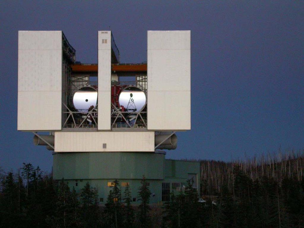
46 Very Large Telescope Secondary mirror Primary mirror Adapted from: Very Large Telescope project
47 Observatory and Observatory site All telescope can be benefited by placing in an observatory (sometimes known as the dome ) Classic design: a hemispherical roof with a open slot, rotating on a circular wall Choosing good sites means that majority of world s largest telescopes are located in a few places, e.g. Hawaii, Chile, Arizona, Canary Island Criteria: away from light pollution, clean atmosphere (low dust and water), height, accessibility, steady atmosphere,

 VLT (very large telescope) world")
48 Observatories Observatories Twin 10-meter Keck telescopes largest optical telescopes in the U.S. (in Hawaii) VLT (very large telescope) world s largest optical telescope (in Chile)
49


50 The telescope is located near Mt. Pastukhova at an altitude of 2070 m above sea level The main mirror is parabolic in shape and has a focal length of 24 meters. The diameter of the main mirror is 605 cm The Bolshoi Teleskop Azimutalnyi, or Big Alt-azimuth Telescope, largest in the world from 1976 to 1991.
51 Table of reflecting telescopes

52 Gases in our atmosphere such as ozone, carbon dioxide, and water vapor strongly absorb infrared, ultraviolet, and shorter wavelengths Some infrared radiation can penetrate the atmosphere through regions called atmospheric windows


53 Observatories in Space Since our atmosphere absorbs much of the infrared, ultraviolet, and X-rays given off by objects, many telescopes are placed in orbit around Earth above the atmosphere The blurring of the atmosphere creates scintillation, or the twinkling of stars Slight variations in the atmosphere s temperature can cause the path of the light from the star to change slightly

54 The Great Observatories Space Program
 infrared and")
55 The Hubble Space Telescope Launched in 1990; maintained and upgraded by several space shuttle service missions throughout the 1990s and early 2000 s Avoids turbulence in the Earth s atmosphere Extends imaging and spectroscopy to (invisible) infrared and ultraviolet
 Diameter")

56 Hubble Space Telescope (launched 1990) Diameter of mirror = 2.4 meters Angular resolution = 0.05 arcseconds
 much higher resolution and sensitivity. Will also observe infrared, whereas Hubble is best at visible light.")
57 The James Webb Space Telescope It s only a model Will have diameter 6.5 meters (vs. HST 2.5 meters) much higher resolution and sensitivity. Will also observe infrared, whereas Hubble is best at visible light. Expected launch 2013 (
 Launched in 2003, uses a 0.")
58 NASA s Space Infrared Telescope Facility (Now Spitzer Space Telescope) Launched in 2003, uses a 0.85 meter mirror.


59 Other Space Telescopes HESSI: Gamma Rays Chandra: X-rays SIRTF: infrared

60 Space Observatories vs Ground-Based Observatories Ground-based telescopes will remain larger than orbiting telescopes Space telescopes can be expensive to build, put into place, and maintain Astronomers must find places free of light pollution for ground-based telescopes


61 Microscopes Objective Image plane #1 Eyepiece M 1 M 2 Microscopes work on the same principle as telescopes, except that the object is really close and we wish to magnify it. When two lenses are used, it s called a compound microscope.

62 Microscope Need a very small focal length! s o L d L-tube length f o f o f e Objective Intermediate Image Eyepiece L>>f e,f o f mic <<f e,f o So we have one big magnifier with short focal length 25 L mα = f = = m m 25/ mic α, eye obj fe fo Angular magnification of the microscope is a product of angular magnification of the eyepiece and transverse magnification of the objective


63 Microscope terminology


64 Finite and Infinity Optical Systems


65 Microscope Objectives Amici Objective Many creative designs exist for microscope objectives. Example: the Burch reflecting microscope objective: Object To eyepiece


66 Getting in Focus
Optical Systems: Pinhole Camera Pinhole camera: simple hole in a box: Called Camera Obscura Aristotle discussed, Al-Hazen analyzed in Book of Optics
 Optical Systems: Pinhole Camera Pinhole camera: simple hole in a box: Called Camera Obscura Aristotle discussed, Al-Hazen analyzed in Book of Optics 1011CE Restricts rays: acts as a single lens: inverts
Geometrical Optics Optical systems
 Phys 322 Lecture 16 Chapter 5 Geometrical Optics Optical systems Magnifying glass Purpose: enlarge a nearby object by increasing its image size on retina Requirements: Image should not be inverted Image
Performance Factors. Technical Assistance. Fundamental Optics
 Performance Factors After paraxial formulas have been used to select values for component focal length(s) and diameter(s), the final step is to select actual lenses. As in any engineering problem, this
Applied Optics. , Physics Department (Room #36-401) , ,
 , ,") Applied Optics Professor, Physics Department (Room #36-401) 2290-0923, 019-539-0923, shsong@hanyang.ac.kr Office Hours Mondays 15:00-16:30, Wednesdays 15:00-16:30 TA (Ph.D. student, Room #36-415) 2290-0921,
Applied Optics Professor, Physics Department (Room #36-401) 2290-0923, 019-539-0923, shsong@hanyang.ac.kr Office Hours Mondays 15:00-16:30, Wednesdays 15:00-16:30 TA (Ph.D. student, Room #36-415) 2290-0921,
Average: Standard Deviation: Max: 99 Min: 40
 1 st Midterm Exam Average: 83.1 Standard Deviation: 12.0 Max: 99 Min: 40 Please contact me to fix an appointment, if you took less than 65. Chapter 33 Lenses and Op/cal Instruments Units of Chapter 33
Lecture 2: Geometrical Optics. Geometrical Approximation. Lenses. Mirrors. Optical Systems. Images and Pupils. Aberrations.
 Lecture 2: Geometrical Optics Outline 1 Geometrical Approximation 2 Lenses 3 Mirrors 4 Optical Systems 5 Images and Pupils 6 Aberrations Christoph U. Keller, Leiden Observatory, keller@strw.leidenuniv.nl
Reflectors vs. Refractors
 1 Telescope Types - Telescopes collect and concentrate light (which can then be magnified, dispersed as a spectrum, etc). - In the end it is the collecting area that counts. - There are two primary telescope
Waves & Oscillations
 Physics 42200 Waves & Oscillations Lecture 33 Geometric Optics Spring 2013 Semester Matthew Jones Aberrations We have continued to make approximations: Paraxial rays Spherical lenses Index of refraction
Applications of Optics
 Nicholas J. Giordano www.cengage.com/physics/giordano Chapter 26 Applications of Optics Marilyn Akins, PhD Broome Community College Applications of Optics Many devices are based on the principles of optics
Chapter 36. Image Formation
 Chapter 36 Image Formation Image of Formation Images can result when light rays encounter flat or curved surfaces between two media. Images can be formed either by reflection or refraction due to these
Geometric optics & aberrations
 Geometric optics & aberrations Department of Astrophysical Sciences University AST 542 http://www.northerneye.co.uk/ Outline Introduction: Optics in astronomy Basics of geometric optics Paraxial approximation
Chapter 36. Image Formation
 Chapter 36 Image Formation Notation for Mirrors and Lenses The object distance is the distance from the object to the mirror or lens Denoted by p The image distance is the distance from the image to the
Lecture 4: Geometrical Optics 2. Optical Systems. Images and Pupils. Rays. Wavefronts. Aberrations. Outline
 Lecture 4: Geometrical Optics 2 Outline 1 Optical Systems 2 Images and Pupils 3 Rays 4 Wavefronts 5 Aberrations Christoph U. Keller, Leiden University, keller@strw.leidenuniv.nl Lecture 4: Geometrical
There is a range of distances over which objects will be in focus; this is called the depth of field of the lens. Objects closer or farther are
 Chapter 25 Optical Instruments Some Topics in Chapter 25 Cameras The Human Eye; Corrective Lenses Magnifying Glass Telescopes Compound Microscope Aberrations of Lenses and Mirrors Limits of Resolution
Lecture Outline Chapter 27. Physics, 4 th Edition James S. Walker. Copyright 2010 Pearson Education, Inc.
 Lecture Outline Chapter 27 Physics, 4 th Edition James S. Walker Chapter 27 Optical Instruments Units of Chapter 27 The Human Eye and the Camera Lenses in Combination and Corrective Optics The Magnifying
PHYSICS FOR THE IB DIPLOMA CAMBRIDGE UNIVERSITY PRESS
 Option C Imaging C Introduction to imaging Learning objectives In this section we discuss the formation of images by lenses and mirrors. We will learn how to construct images graphically as well as algebraically.
PHYSICS. Chapter 35 Lecture FOR SCIENTISTS AND ENGINEERS A STRATEGIC APPROACH 4/E RANDALL D. KNIGHT
 PHYSICS FOR SCIENTISTS AND ENGINEERS A STRATEGIC APPROACH 4/E Chapter 35 Lecture RANDALL D. KNIGHT Chapter 35 Optical Instruments IN THIS CHAPTER, you will learn about some common optical instruments and
OPTICAL IMAGING AND ABERRATIONS
 OPTICAL IMAGING AND ABERRATIONS PARTI RAY GEOMETRICAL OPTICS VIRENDRA N. MAHAJAN THE AEROSPACE CORPORATION AND THE UNIVERSITY OF SOUTHERN CALIFORNIA SPIE O P T I C A L E N G I N E E R I N G P R E S S A
The Imaging Chain in Optical Astronomy
 The Imaging Chain in Optical Astronomy 1 Review and Overview Imaging Chain includes these elements: 1. energy source 2. object 3. collector 4. detector (or sensor) 5. processor 6. display 7. analysis 8.
The Imaging Chain in Optical Astronomy
 The Imaging Chain in Optical Astronomy Review and Overview Imaging Chain includes these elements: 1. energy source 2. object 3. collector 4. detector (or sensor) 5. processor 6. display 7. analysis 8.
Ch 24. Geometric Optics
 text concept Ch 24. Geometric Optics Fig. 24 3 A point source of light P and its image P, in a plane mirror. Angle of incidence =angle of reflection. text. Fig. 24 4 The blue dashed line through object
25 cm. 60 cm. 50 cm. 40 cm.
 Geometrical Optics 7. The image formed by a plane mirror is: (a) Real. (b) Virtual. (c) Erect and of equal size. (d) Laterally inverted. (e) B, c, and d. (f) A, b and c. 8. A real image is that: (a) Which
Two Fundamental Properties of a Telescope
 Two Fundamental Properties of a Telescope 1. Angular Resolution smallest angle which can be seen = 1.22 / D 2. Light-Collecting Area The telescope is a photon bucket A = (D/2)2 D A Parts of the Human Eye
University of Rochester Department of Physics and Astronomy Physics123, Spring Homework 5 - Solutions
 Problem 5. University of Rochester Department of Physics and Astronomy Physics23, Spring 202 Homework 5 - Solutions An optometrist finds that a farsighted person has a near point at 25 cm. a) If the eye
Chapter 25 Optical Instruments
 Chapter 25 Optical Instruments Units of Chapter 25 Cameras, Film, and Digital The Human Eye; Corrective Lenses Magnifying Glass Telescopes Compound Microscope Aberrations of Lenses and Mirrors Limits of
Chapter 25. Optical Instruments
 Chapter 25 Optical Instruments Optical Instruments Analysis generally involves the laws of reflection and refraction Analysis uses the procedures of geometric optics To explain certain phenomena, the wave
Chapter Ray and Wave Optics
 109 Chapter Ray and Wave Optics 1. An astronomical telescope has a large aperture to [2002] reduce spherical aberration have high resolution increase span of observation have low dispersion. 2. If two
ECEN 4606, UNDERGRADUATE OPTICS LAB
 ECEN 4606, UNDERGRADUATE OPTICS LAB Lab 2: Imaging 1 the Telescope Original Version: Prof. McLeod SUMMARY: In this lab you will become familiar with the use of one or more lenses to create images of distant
Lecture 15 Chap. 6 Optical Instruments. Single lens instruments Eyeglasses Magnifying glass. Two lens Telescope & binoculars Microscope
 Lecture 15 Chap. 6 Optical Instruments Single lens instruments Eyeglasses Magnifying glass Two lens Telescope & binoculars Microscope The projector Projection lens Field lens October 12, 2010 all these
INTRODUCTION THIN LENSES. Introduction. given by the paraxial refraction equation derived last lecture: Thin lenses (19.1) = 1. Double-lens systems
 = 1. Double-lens systems") Chapter 9 OPTICAL INSTRUMENTS Introduction Thin lenses Double-lens systems Aberrations Camera Human eye Compound microscope Summary INTRODUCTION Knowledge of geometrical optics, diffraction and interference,
Chapter 9 OPTICAL INSTRUMENTS Introduction Thin lenses Double-lens systems Aberrations Camera Human eye Compound microscope Summary INTRODUCTION Knowledge of geometrical optics, diffraction and interference,
Magnification, stops, mirrors More geometric optics
 Magnification, stops, mirrors More geometric optics D. Craig 2005-02-25 Transverse magnification Refer to figure 5.22. By convention, distances above the optical axis are taken positive, those below, negative.
Lecture PowerPoint. Chapter 25 Physics: Principles with Applications, 6 th edition Giancoli
 Lecture PowerPoint Chapter 25 Physics: Principles with Applications, 6 th edition Giancoli 2005 Pearson Prentice Hall This work is protected by United States copyright laws and is provided solely for the
Astronomy 80 B: Light. Lecture 9: curved mirrors, lenses, aberrations 29 April 2003 Jerry Nelson
 Astronomy 80 B: Light Lecture 9: curved mirrors, lenses, aberrations 29 April 2003 Jerry Nelson Sensitive Countries LLNL field trip 2003 April 29 80B-Light 2 Topics for Today Optical illusion Reflections
Some lens design methods. Dave Shafer David Shafer Optical Design Fairfield, CT #
 Some lens design methods Dave Shafer David Shafer Optical Design Fairfield, CT 06824 #203-259-1431 shaferlens@sbcglobal.net Where do we find our ideas about how to do optical design? You probably won t
Why is There a Black Dot when Defocus = 1λ?
 Why is There a Black Dot when Defocus = 1λ? W = W 020 = a 020 ρ 2 When a 020 = 1λ Sag of the wavefront at full aperture (ρ = 1) = 1λ Sag of the wavefront at ρ = 0.707 = 0.5λ Area of the pupil from ρ =
Converging and Diverging Surfaces. Lenses. Converging Surface
 Lenses Sandy Skoglund 2 Converging and Diverging s AIR Converging If the surface is convex, it is a converging surface in the sense that the parallel rays bend toward each other after passing through the
Phys 2310 Mon. Oct. 16, 2017 Today s Topics. Finish Chapter 34: Geometric Optics Homework this Week
 Phys 2310 Mon. Oct. 16, 2017 Today s Topics Finish Chapter 34: Geometric Optics Homework this Week 1 Homework this Week (HW #10) Homework this week due Mon., Oct. 23: Chapter 34: #47, 57, 59, 60, 61, 62,
Big League Cryogenics and Vacuum The LHC at CERN
 Big League Cryogenics and Vacuum The LHC at CERN A typical astronomical instrument must maintain about one cubic meter at a pressure of
OPAC 202 Optical Design and Inst.
 OPAC 202 Optical Design and Inst. Topic 9 Aberrations Department of http://www.gantep.edu.tr/~bingul/opac202 Optical & Acustical Engineering Gaziantep University Apr 2018 Sayfa 1 Introduction The influences
Optics and Telescopes
 Optics and Telescopes Properties of Light Law of Reflection - reflection Angle of Incidence = Angle of Law of Refraction - Light beam is bent towards the normal when passing into a medium of higher Index
Lecture 3: Geometrical Optics 1. Spherical Waves. From Waves to Rays. Lenses. Chromatic Aberrations. Mirrors. Outline
 Lecture 3: Geometrical Optics 1 Outline 1 Spherical Waves 2 From Waves to Rays 3 Lenses 4 Chromatic Aberrations 5 Mirrors Christoph U. Keller, Leiden Observatory, keller@strw.leidenuniv.nl Lecture 3: Geometrical
Image Formation. Light from distant things. Geometrical optics. Pinhole camera. Chapter 36
 Light from distant things Chapter 36 We learn about a distant thing from the light it generates or redirects. The lenses in our eyes create images of objects our brains can process. This chapter concerns
Option G 2: Lenses. The diagram below shows the image of a square grid as produced by a lens that does not cause spherical aberration.
 Name: Date: Option G 2: Lenses 1. This question is about spherical aberration. The diagram below shows the image of a square grid as produced by a lens that does not cause spherical aberration. In the
Lens Design I. Lecture 3: Properties of optical systems II Herbert Gross. Summer term
 Lens Design I Lecture 3: Properties of optical systems II 207-04-20 Herbert Gross Summer term 207 www.iap.uni-jena.de 2 Preliminary Schedule - Lens Design I 207 06.04. Basics 2 3.04. Properties of optical
OPTICAL SYSTEMS OBJECTIVES
 101 L7 OPTICAL SYSTEMS OBJECTIVES Aims Your aim here should be to acquire a working knowledge of the basic components of optical systems and understand their purpose, function and limitations in terms
Introduction. Geometrical Optics. Milton Katz State University of New York. VfeWorld Scientific New Jersey London Sine Singapore Hong Kong
 Introduction to Geometrical Optics Milton Katz State University of New York VfeWorld Scientific «New Jersey London Sine Singapore Hong Kong TABLE OF CONTENTS PREFACE ACKNOWLEDGMENTS xiii xiv CHAPTER 1:
Phys 102 Lecture 21 Optical instruments
 Phys 102 Lecture 21 Optical instruments 1 Today we will... Learn how combinations of lenses form images Thin lens equation & magnification Learn about the compound microscope Eyepiece & objective Total
Lens Design I. Lecture 3: Properties of optical systems II Herbert Gross. Summer term
 Lens Design I Lecture 3: Properties of optical systems II 205-04-8 Herbert Gross Summer term 206 www.iap.uni-jena.de 2 Preliminary Schedule 04.04. Basics 2.04. Properties of optical systrems I 3 8.04.
Laboratory experiment aberrations
 Laboratory experiment aberrations Obligatory laboratory experiment on course in Optical design, SK2330/SK3330, KTH. Date Name Pass Objective This laboratory experiment is intended to demonstrate the most
Physics Chapter Review Chapter 25- The Eye and Optical Instruments Ethan Blitstein
 Physics Chapter Review Chapter 25- The Eye and Optical Instruments Ethan Blitstein The Human Eye As light enters through the human eye it first passes through the cornea (a thin transparent membrane of
Lecture 21. Physics 1202: Lecture 21 Today s Agenda
 Physics 1202: Lecture 21 Today s Agenda Announcements: Team problems today Team 14: Gregory Desautels, Benjamin Hallisey, Kyle Mcginnis Team 15: Austin Dion, Nicholas Gandza, Paul Macgillis-Falcon Homework
Chapter 9 - Ray Optics and Optical Instruments. The image distance can be obtained using the mirror formula:
 Question 9.1: A small candle, 2.5 cm in size is placed at 27 cm in front of a concave mirror of radius of curvature 36 cm. At what distance from the mirror should a screen be placed in order to obtain
ECEG105/ECEU646 Optics for Engineers Course Notes Part 4: Apertures, Aberrations Prof. Charles A. DiMarzio Northeastern University Fall 2008
 ECEG105/ECEU646 Optics for Engineers Course Notes Part 4: Apertures, Aberrations Prof. Charles A. DiMarzio Northeastern University Fall 2008 July 2003+ Chuck DiMarzio, Northeastern University 11270-04-1
G1 THE NATURE OF EM WAVES AND LIGHT SOURCES
 G1 THE NATURE OF EM WAVES AND LIGHT SOURCES G2 OPTICAL INSTRUMENTS HW/Study Packet Required: READ Tsokos, pp 598-620 SL/HL Supplemental: Hamper, pp 411-450 DO Questions p 605 #1,3 pp 621-623 #6,8,15,18,19,24,26
GEOMETRICAL OPTICS AND OPTICAL DESIGN
 GEOMETRICAL OPTICS AND OPTICAL DESIGN Pantazis Mouroulis Associate Professor Center for Imaging Science Rochester Institute of Technology John Macdonald Senior Lecturer Physics Department University of
Activity 6.1 Image Formation from Spherical Mirrors
 PHY385H1F Introductory Optics Practicals Day 6 Telescopes and Microscopes October 31, 2011 Group Number (number on Intro Optics Kit):. Facilitator Name:. Record-Keeper Name: Time-keeper:. Computer/Wiki-master:..
Physics II. Chapter 23. Spring 2018
 Physics II Chapter 23 Spring 2018 IMPORTANT: Except for multiple-choice questions, you will receive no credit if you show only an answer, even if the answer is correct. Always show in the space on your
Chapters 1 & 2. Definitions and applications Conceptual basis of photogrammetric processing
 Chapters 1 & 2 Chapter 1: Photogrammetry Definitions and applications Conceptual basis of photogrammetric processing Transition from two-dimensional imagery to three-dimensional information Automation
Exam Preparation Guide Geometrical optics (TN3313)
") Exam Preparation Guide Geometrical optics (TN3313) Lectures: September - December 2001 Version of 21.12.2001 When preparing for the exam, check on Blackboard for a possible newer version of this guide.
Exam Preparation Guide Geometrical optics (TN3313) Lectures: September - December 2001 Version of 21.12.2001 When preparing for the exam, check on Blackboard for a possible newer version of this guide.
Chapter 18 Optical Elements
 Chapter 18 Optical Elements GOALS When you have mastered the content of this chapter, you will be able to achieve the following goals: Definitions Define each of the following terms and use it in an operational
Chapter 34 Geometric Optics (also known as Ray Optics) by C.-R. Hu
 by C.-R. Hu") Chapter 34 Geometric Optics (also known as Ray Optics) by C.-R. Hu 1. Principles of image formation by mirrors (1a) When all length scales of objects, gaps, and holes are much larger than the wavelength
Chapter 34 Geometric Optics (also known as Ray Optics) by C.-R. Hu 1. Principles of image formation by mirrors (1a) When all length scales of objects, gaps, and holes are much larger than the wavelength
Chapter 3 Op+cal Instrumenta+on
 Chapter 3 Op+cal Instrumenta+on 3-1 Stops, Pupils, and Windows 3-4 The Camera 3-5 Simple Magnifiers and Eyepieces 3-6 Microscopes 3-7 Telescopes Today (2011-09-22) 1. Magnifiers 2. Camera 3. Resolution
Dr. Todd Satogata (ODU/Jefferson Lab) Monday, April
 Monday, April") University Physics 227N/232N Mirrors and Lenses Homework Optics 2 due Friday AM Quiz Friday Optional review session next Monday (Apr 28) Bring Homework Notebooks to Final for Grading Dr. Todd Satogata
University Physics 227N/232N Mirrors and Lenses Homework Optics 2 due Friday AM Quiz Friday Optional review session next Monday (Apr 28) Bring Homework Notebooks to Final for Grading Dr. Todd Satogata
EE119 Introduction to Optical Engineering Spring 2002 Final Exam. Name:
 EE119 Introduction to Optical Engineering Spring 2002 Final Exam Name: SID: CLOSED BOOK. FOUR 8 1/2 X 11 SHEETS OF NOTES, AND SCIENTIFIC POCKET CALCULATOR PERMITTED. TIME ALLOTTED: 180 MINUTES Fundamental
Chapter 34 The Wave Nature of Light; Interference. Copyright 2009 Pearson Education, Inc.
 Chapter 34 The Wave Nature of Light; Interference 34-7 Luminous Intensity The intensity of light as perceived depends not only on the actual intensity but also on the sensitivity of the eye at different
Chapter 3 Op,cal Instrumenta,on
 Imaging by an Op,cal System Change in curvature of wavefronts by a thin lens Chapter 3 Op,cal Instrumenta,on 3-1 Stops, Pupils, and Windows 3-4 The Camera 3-5 Simple Magnifiers and Eyepieces 1. Magnifiers
Chapter 34: Geometric Optics
 Chapter 34: Geometric Optics It is all about images How we can make different kinds of images using optical devices Optical device example: mirror, a piece of glass, telescope, microscope, kaleidoscope,
Binocular and Scope Performance 57. Diffraction Effects
 Binocular and Scope Performance 57 Diffraction Effects The resolving power of a perfect optical system is determined by diffraction that results from the wave nature of light. An infinitely distant point
UNIVERSITY OF NAIROBI COLLEGE OF EDUCATION AND EXTERNAL STUDIES
 UNIVERSITY OF NAIROBI COLLEGE OF EDUCATION AND EXTERNAL STUDIES COURSE TITLE: BED (SCIENCE) UNIT TITLE: WAVES AND OPTICS UNIT CODE: SPH 103 UNIT AUTHOR: PROF. R.O. GENGA DEPARTMENT OF PHYSICS UNIVERSITY
Chapter 36. Image Formation
 Chapter 36 Image Formation Image of Formation Images can result when light rays encounter flat or curved surfaces between two media. Images can be formed either by reflection or refraction due to these
PHY385H1F Introductory Optics Term Test 2 November 6, 2012 Duration: 50 minutes. NAME: Student Number:.
 PHY385H1F Introductory Optics Term Test 2 November 6, 2012 Duration: 50 minutes NAME: Student Number:. Aids allowed: A pocket calculator with no communication ability. One 8.5x11 aid sheet, written on
COURSE NAME: PHOTOGRAPHY AND AUDIO VISUAL PRODUCTION (VOCATIONAL) FOR UNDER GRADUATE (FIRST YEAR)
 FOR UNDER GRADUATE (FIRST YEAR)") COURSE NAME: PHOTOGRAPHY AND AUDIO VISUAL PRODUCTION (VOCATIONAL) FOR UNDER GRADUATE (FIRST YEAR) PAPER TITLE: BASIC PHOTOGRAPHIC UNIT - 3 : SIMPLE LENS TOPIC: LENS PROPERTIES AND DEFECTS OBJECTIVES By
COURSE NAME: PHOTOGRAPHY AND AUDIO VISUAL PRODUCTION (VOCATIONAL) FOR UNDER GRADUATE (FIRST YEAR) PAPER TITLE: BASIC PHOTOGRAPHIC UNIT - 3 : SIMPLE LENS TOPIC: LENS PROPERTIES AND DEFECTS OBJECTIVES By
GEOMETRICAL OPTICS Practical 1. Part I. BASIC ELEMENTS AND METHODS FOR CHARACTERIZATION OF OPTICAL SYSTEMS
 GEOMETRICAL OPTICS Practical 1. Part I. BASIC ELEMENTS AND METHODS FOR CHARACTERIZATION OF OPTICAL SYSTEMS Equipment and accessories: an optical bench with a scale, an incandescent lamp, matte, a set of
Phy Ph s y 102 Lecture Lectur 21 Optical instruments 1
 Phys 102 Lecture 21 Optical instruments 1 Today we will... Learn how combinations of lenses form images Thin lens equation & magnification Learn about the compound microscope Eyepiece & objective Total
Laboratory 7: Properties of Lenses and Mirrors
 Laboratory 7: Properties of Lenses and Mirrors Converging and Diverging Lens Focal Lengths: A converging lens is thicker at the center than at the periphery and light from an object at infinity passes
Optical Components for Laser Applications. Günter Toesko - Laserseminar BLZ im Dezember
 Günter Toesko - Laserseminar BLZ im Dezember 2009 1 Aberrations An optical aberration is a distortion in the image formed by an optical system compared to the original. It can arise for a number of reasons
Section A Conceptual and application type questions. 1 Which is more observable diffraction of light or sound? Justify. (1)
") INDIAN SCHOOL MUSCAT Department of Physics Class : XII Physics Worksheet - 6 (2017-2018) Chapter 9 and 10 : Ray Optics and wave Optics Section A Conceptual and application type questions 1 Which is more
INDIAN SCHOOL MUSCAT Department of Physics Class : XII Physics Worksheet - 6 (2017-2018) Chapter 9 and 10 : Ray Optics and wave Optics Section A Conceptual and application type questions 1 Which is more
Chapter 34. Images. Copyright 2014 John Wiley & Sons, Inc. All rights reserved.
 Chapter 34 Images Copyright 34-1 Images and Plane Mirrors Learning Objectives 34.01 Distinguish virtual images from real images. 34.02 Explain the common roadway mirage. 34.03 Sketch a ray diagram for
Area of the Secondary Mirror Obscuration Ratio = Area of the EP Ignoring the Obscuration
 Compact Gregorian Telescope Design a compact 10X25 Gregorian telescope. The Gregorian telescope provides an erect image and consists of two concave mirrors followed by an eyepiece to produce an afocal
Warren J. Smith Chief Scientist, Consultant Rockwell Collins Optronics Carlsbad, California
 Modern Optical Engineering The Design of Optical Systems Warren J. Smith Chief Scientist, Consultant Rockwell Collins Optronics Carlsbad, California Fourth Edition Me Graw Hill New York Chicago San Francisco
Cardinal Points of an Optical System--and Other Basic Facts
 Cardinal Points of an Optical System--and Other Basic Facts The fundamental feature of any optical system is the aperture stop. Thus, the most fundamental optical system is the pinhole camera. The image
Lens Design II. Lecture 11: Further topics Herbert Gross. Winter term
 Lens Design II Lecture : Further topics 28--8 Herbert Gross Winter term 27 www.iap.uni-ena.de 2 Preliminary Schedule Lens Design II 27 6.. Aberrations and optimization Repetition 2 23.. Structural modifications
Unit 2: Optics Part 2
 Unit 2: Optics Part 2 Refraction of Visible Light 1. Bent-stick effect: When light passes from one medium to another (for example, when a beam of light passes through air and into water, or vice versa),
SUBJECT: PHYSICS. Use and Succeed.
 SUBJECT: PHYSICS I hope this collection of questions will help to test your preparation level and useful to recall the concepts in different areas of all the chapters. Use and Succeed. Navaneethakrishnan.V
Advanced Lens Design
 Advanced Lens Design Lecture 3: Aberrations I 214-11-4 Herbert Gross Winter term 214 www.iap.uni-jena.de 2 Preliminary Schedule 1 21.1. Basics Paraxial optics, imaging, Zemax handling 2 28.1. Optical systems
Chapter 3 Optical Systems
 Chapter 3 Optical Systems The Human Eye [Reading Assignment, Hecht 5.7.1-5.7.3; see also Smith Chapter 5] retina aqueous vitreous fovea-macula cornea lens blind spot optic nerve iris cornea f b aqueous
 Telecentric Imaging Object space telecentricity stop source: edmund optics The 5 classical Seidel Aberrations First order aberrations Spherical Aberration (~r 4 ) Origin: different focal lengths for different
Reading: Lenses and Mirrors; Applications Key concepts: Focal points and lengths; real images; virtual images; magnification; angular magnification.
 Reading: Lenses and Mirrors; Applications Key concepts: Focal points and lengths; real images; virtual images; magnification; angular magnification. 1.! Questions about objects and images. Can a virtual
Physics 1C. Lecture 25B
 Physics 1C Lecture 25B "More than 50 years ago, Austrian researcher Ivo Kohler gave people goggles thats severely distorted their vision: The lenses turned the world upside down. After several weeks, subjects
Chapter 2 - Geometric Optics
 David J. Starling Penn State Hazleton PHYS 214 The human eye is a visual system that collects light and forms an image on the retina. The human eye is a visual system that collects light and forms an image
Introduction to Optical Modeling. Friedrich-Schiller-University Jena Institute of Applied Physics. Lecturer: Prof. U.D. Zeitner
 Introduction to Optical Modeling Friedrich-Schiller-University Jena Institute of Applied Physics Lecturer: Prof. U.D. Zeitner The Nature of Light Fundamental Question: What is Light? Newton Huygens / Maxwell
CH. 23 Mirrors and Lenses HW# 6, 7, 9, 11, 13, 21, 25, 31, 33, 35
 CH. 23 Mirrors and Lenses HW# 6, 7, 9, 11, 13, 21, 25, 31, 33, 35 Mirrors Rays of light reflect off of mirrors, and where the reflected rays either intersect or appear to originate from, will be the location
Waves & Oscillations
 Physics 42200 Waves & Oscillations Lecture 27 Geometric Optics Spring 205 Semester Matthew Jones Sign Conventions > + = Convex surface: is positive for objects on the incident-light side is positive for
CHAPTER 33 ABERRATION CURVES IN LENS DESIGN
 CHAPTER 33 ABERRATION CURVES IN LENS DESIGN Donald C. O Shea Georgia Institute of Technology Center for Optical Science and Engineering and School of Physics Atlanta, Georgia Michael E. Harrigan Eastman
Chapter 23. Geometrical Optics: Mirrors and Lenses and other Instruments
 Chapter 23 Geometrical Optics: Mirrors and Lenses and other Instruments HITT 1 You stand two feet away from a plane mirror. How far is it from you to your image? a. 2.0 ft b. 3.0 ft c. 4.0 ft d. 5.0 ft
Physics 1202: Lecture 19 Today s Agenda
 Physics 1202: Lecture 19 Today s Agenda Announcements: Team problems today Team 12: Kervell Baird, Matthew George, Derek Schultz Team 13: Paxton Stowik, Stacey Ann Burke Team 14: Gregory Desautels, Benjamin
Geometrical Optics for AO Claire Max UC Santa Cruz CfAO 2009 Summer School
 Geometrical Optics for AO Claire Max UC Santa Cruz CfAO 2009 Summer School Page 1 Some tools for active learning In-class conceptual questions will aim to engage you in more active learning and provide
Opti 415/515. Introduction to Optical Systems. Copyright 2009, William P. Kuhn
 Opti 415/515 Introduction to Optical Systems 1 Optical Systems Manipulate light to form an image on a detector. Point source microscope Hubble telescope (NASA) 2 Fundamental System Requirements Application
PHYS 202 OUTLINE FOR PART III LIGHT & OPTICS
 PHYS 202 OUTLINE FOR PART III LIGHT & OPTICS Electromagnetic Waves A. Electromagnetic waves S-23,24 1. speed of waves = 1/( o o ) ½ = 3 x 10 8 m/s = c 2. waves and frequency: the spectrum (a) radio red