Geometrical Optics for AO Claire Max UC Santa Cruz CfAO 2009 Summer School
|
|
|
- Elmer Goodwin
- 5 years ago
- Views:
Transcription


1 Geometrical Optics for AO Claire Max UC Santa Cruz CfAO 2009 Summer School Page 1
2 Some tools for active learning In-class conceptual questions will aim to engage you in more active learning and provide me with feedback on whether concepts are clear I will pose a short conceptual question (no calculations) I will ask you to first formulate your own answer, then discuss your answer with two other students, finally to report your consensus answer to the class Some web-sites & books about teaching and learning: How People Learn, Bransford, Brown, and Cocking, Editors; National Research Council, National Academy Press Page 2
3 Goals of this lecture Review of Geometrical Optics Understand the tools used for optical design of AO systems Understand what wavefront aberrations look like, and how to describe them Characterization of the aberrations caused by turbulence in the Earth s atmosphere What the optics of a simple AO system look like Page 3
4 Keck AO system optical layout: why does it look like this?? Page 4
5 Simplest schematic of an AO system PUPIL BEAMSPLITTER WAVEFRONT SENSOR COLLIMATING LENS OR MIRROR FOCUSING LENS OR MIRROR Optical elements are portrayed as transmitting, for simplicity: they may be lenses or mirrors Page 5
6 What optics concepts are needed for AO? Design of AO system itself: What determines the size and position of the deformable mirror? Of the wavefront sensor? What does it mean to say that the deformable mirror is conjugate to the telescope pupil? How do you fit an AO system onto a modest-sized optical bench, if it s supposed to correct an 8-10m primary mirror? What are optical aberrations? How are aberrations induced by atmosphere related to those seen in lab? Page 6
7 Levels of models in optics Geometric optics - rays, reflection, refraction Physical optics (Fourier optics) - diffraction, scalar waves Electromagnetics - vector waves, polarization Quantum optics - photons, interaction with matter, lasers Page 7
8 Review of geometrical optics: lenses, mirrors, and imaging Rays and wavefronts Laws of refraction and reflection Imaging Pinhole camera Lenses Mirrors Resolution and depth of field Note: Adapted in part from material created by MIT faculty member Prof. George Barbastathis, Reproduced under MIT s OpenCourseWare policies, George Barbastathis. Page 8
9 Rays and wavefronts Page 9
10 Rays and wavefronts In homogeneous media, light propagates in straight lines Page 10
11 Spherical waves and plane waves Page 11
12 Refraction at a surface: Snell s s Law Medium 1, index of refraction n Medium 2, index of refraction n Snell s law: nsin! = n" sin!" Page 12
13 Reflection at a surface Angle of incidence equals angle of reflection Page 13
14 Huygens Principle Every point in a wavefront acts as a little secondary light source, and emits a spherical wave The propagating wavefront is the result of superposing all these little spherical waves Destructive interference in all but the direction of propagation Page 14

15 Why are imaging systems needed? Every point in the object scatters an incident light into a spherical wave The spherical waves from all the points on the object s surface get mixed together as they propagate toward you An imaging system reassigns (focuses) all the rays from a single point on the object onto another point in space (the focal point ), so you can distinguish details of the object. Page 15
 Also, diffraction of light as it passes through the small pinhole produces artifacts in the image.")
16 Pinhole camera is simplest imaging instrument Opaque screen with a pinhole blocks all but one ray per object point from reaching the image space. An image is formed (upside down). Good news. BUT most of the light is wasted (it is stopped by the opaque sheet) Also, diffraction of light as it passes through the small pinhole produces artifacts in the image. Page 16
17 Imaging with lenses: doesn t t throw away as much light as pinhole camera Collects all rays that pass through solidangle of lens Page 17
18 Paraxial approximation or first order optics or Gaussian optics Angle of rays with respect to optical axis is small First-order Taylor expansions: sin ε tan ε ε, cos ε 1, (1 + ε) 1/2 1 + ε / 2 Page 18
19 Thin lenses, part 1 D = lens diam. Definition: f-number f / # f / D Page 19
20 Thin lenses, part 2 D = lens diam. Page 20
21 Page 21
22 Ray-tracing with a thin lens Image point (focus) is located at intersection of ALL rays passing through the lens from the corresponding object point Easiest way to see this: trace rays passing through the two foci, and through the center of the lens (the chief ray ) and the edges of the lens Page 22
23 Refraction and the Lens-users Equation Any ray that goes through the focal point on its way to the lens will come out parallel to the optical axis. (ray 1) f f ray 1 Credit: J. Holmes, Christian Brothers Univ. Page 23
24 Refraction and the Lens-users Equation Any ray that goes through the focal point on its way from the lens, must go into the lens parallel to the optical axis. (ray 2) f f ray 1 ray 2 Page 24
25 Refraction and the Lens-users Equation Any ray that goes through the center of the lens must go essentially undeflected. (ray 3) object f f image ray 1 ray 3 ray 2 Page 25
26 Refraction and the Lens-users Equation Note that a real image is formed. Note that the image is up-side-down. object f f image ray 1 ray 3 ray 2 Page 26
27 Refraction and the Lens-users Equation By looking at ray 3 alone, we can see by similar triangles that M = h /h = -s /s object h s s f f image h <0 ray 3 Example: f = 10 cm; s = 40 cm; s = 13.3 cm: M = -13.3/40 = Note h is up-side-down and so is < 0 Page 27
28 Definition: Field of view (FOV) of an imaging system Angle that the chief ray from an object can subtend, given the pupil (entrance aperture) of the imaging system Recall that the chief ray propagates through the lens un-deviated Page 28
29 Optical invariant ( = Lagrange invariant) y 1! 1 = y 2! 2 Page 29

30 Lagrange invariant has important consequences for AO on large telescopes From Don Gavel Page 30
31 Refracting telescope 1 f obj = 1 s s 1! 1 s 1 since s 0 " # so s 1! f obj Main point of telescope: to gather more light than eye. Secondarily, to magnify image of the object Magnifying power M tot = - f Objective / f Eyepiece so for high magnification, make f Objective as large as possible (long tube) and make f Eyepiece as short as possible Page 31


32 Lick Observatory s s 36 Refractor: one long telescope! Page 32
33 Concept Question Give an intuitive explanation for why the magnifying power of a refracting telescope is M tot = - f Objective / f Eyepiece Make sketches to illustrate your reasoning Page 33
34 Imaging with mirrors: spherical and parabolic mirrors f = R/2 Spherical surface: in paraxial approx, focuses incoming parallel rays to (approx) a point Parabolic surface: perfect focusing for parallel rays (e.g. satellite dish, radio telescope) Page 34
35 Problems with spherical mirrors Optical aberrations (mostly spherical aberration and coma) Especially if f-number is small ( fast focal ratio, short telescope, big angles) Page 35
36 Focal length of mirrors Focal length of spherical mirror is f sp = R/2 Convention: f is positive if it is to the left of the mirror f Near the optical axis, parabola and sphere are very similar, so that f par = R/2 as well. Page 36
37 Page 37

38 Parabolic mirror: focus in 3D Page 38
39 Mirror equations Imaging condition for spherical mirror 1 s s 1 =! 2 R Focal length f =! R 2 Magnifications M transverse =! s 0 s 1 M angle =! s 1 s 0 Page 39
40 Cassegrain reflecting telescope Parabolic primary mirror Hyperbolic secondary mirror Focus Hyperbolic secondary mirror: 1) reduces off-axis aberrations, 2) shortens physical length of telescope. Can build mirrors with much shorter focal lengths than lenses. Example: 10-meter primary mirrors of Keck Telescopes have focal lengths of 17.5 meters (f/1.75). About same as Lick 36 refractor. Page 40

41 Heuristic derivation of the diffraction limit Courtesy of Don Gavel Page 41

42 Angular resolution and depth of field "# $ % D Diameter D "z = 8 $f 2 # D 2 Diffractive calculation light doesn t focus at a point. Beam Waist has angular width λ / D, and length Δz (depth of field) Page 42
43 Time for a short break Please get up and move around! Page 43
44 Aberrations In optical systems In atmosphere Description in terms of Zernike polynomials Based on slides by Brian Bauman, LLNL and UCSC, and Gary Chanan, UCI Page 44
45 Third order aberrations sin θ terms in Snell s law can be expanded in power series n sin θ = n sin θ n ( θ - θ 3 /3! + θ 5 /5! + ) = n ( θ - θ 3 /3! + θ 5 /5! + ) Paraxial ray approximation: keep only θ terms (first order optics; rays propagate nearly along optical axis) Piston, tilt, defocus Third order aberrations: result from adding θ 3 terms Spherical aberration, coma, astigmatism,... Page 45
46 Different ways to illustrate optical aberrations Side view of a fan of rays (No aberrations) Spot diagram : Image at different focus positions Shows spots where rays would strike a detector Page 46
47 Spherical aberration Rays from a spherically aberrated wavefront focus at different planes Through-focus spot diagram for spherical aberration Page 47

48 Hubble Space Telescope suffered from Spherical Aberration In a Cassegrain telescope, the hyperboloid of the primary mirror must match the specs of the secondary mirror. For HST they didn t match. Page 48
")
49 HST Point Spread Function (image of a point source) Page 49
50 Spherical aberration as the mother of all other aberrations Coma and astigmatism can be thought of as the aberrations from a de-centered bundle of spherically aberrated rays Ray bundle on axis shows spherical aberration only Ray bundle slightly de-centered shows coma Ray bundle more de-centered shows astigmatism All generated from subsets of a larger centered bundle of spherically aberrated rays (diagrams follow) Page 50
51 Spherical aberration as the mother of coma Big bundle of spherically aberrated rays De-centered subset of rays produces coma Page 51

52 Coma Comet -shaped spot Chief ray is at apex of coma pattern Centroid is shifted from chief ray! Centroid shifts with change in focus! Wavefront Page 52
53 Coma Note that centroid shifts: Rays from a comatic wavefront Through-focus spot diagram for coma Page 53
54 Spherical aberration as the mother of astigmatism Big bundle of spherically aberrated rays More-decentered subset of rays produces astigmatism Page 54
55 Astigmatism Top view of rays Through-focus spot diagram for astigmatism Side view of rays Page 55
56 Wavefront for astigmatism Page 56
57 Different view of astigmatism Page 57

58 Where does astigmatism come from? From Ian McLean, UCLA Page 58
59 Concept Question How do you suppose eyeglasses correct for astigmatism? Page 59
60 Off-axis object is equivalent to having a de-centered ray bundle Spherical surface New optical axis Ray bundle from an off-axis object. How to view this as a de-centered ray bundle? For any field angle there will be an optical axis, which is to the surface of the optic and // to the incoming ray bundle. The bundle is de-centered wrt this axis. Page 60
61 Zernike Polynomials Convenient basis set for expressing wavefront aberrations over a circular pupil Zernike polynomials are orthogonal to each other A few different ways to normalize always check definitions! Page 61
62

63 From G. Chanan Piston Tip-tilt
")
64 Astigmatism (3rd order) Defocus

65 Trefoil Coma

66 Ashtray Spherical Astigmatism (5th order)
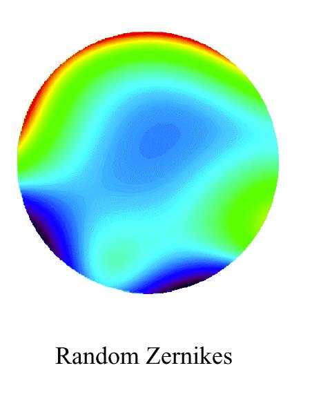
67
68 Units: Radians of phase / (D / r 0 ) 5/6 Tip-tilt is single biggest contributor Focus, astigmatism, coma also big High-order terms go on and on. Reference: Noll
69 Seidel polynomials vs. Zernike polynomials Seidel polynomials also describe aberrations At first glance, Seidel and Zernike aberrations look very similar Zernike aberrations are an orthogonal set of functions used to decompose a given wavefront at a given field point into its components Zernike modes add to the Seidel aberrations the correct amount of low-order modes to minimize rms wavefront error Seidel aberrations are used in optical design to predict the aberrations in a design and how they will vary over the system s field of view The Seidel aberrations have an analytic field-dependence that is proportional to some power of field angle Page 69
70 References for Zernike Polynomials Pivotal Paper: Noll, R. J. 1976, Zernike polynomials and atmospheric turbulence, JOSA 66, page 207 Books: e.g. Hardy, Adaptive Optics, pages Page 70
71 Considerations in the optical design of AO systems: pupil relays Pupil Pupil Pupil Deformable mirror and Shack-Hartmann lenslet array should be optically conjugate to the telescope pupil. What does this mean? Page 71
72 Define some terms Optically conjugate = image of... optical axis object space image space Aperture stop = the aperture that limits the bundle of rays accepted by the optical system symbol for aperture stop Pupil = image of aperture stop Page 72
73 So now we can translate: The deformable mirror should be optically conjugate to the telescope pupil means The surface of the deformable mirror is an image of the telescope pupil where The pupil is an image of the aperture stop In practice, the pupil is usually the primary mirror of the telescope Page 73
74 Considerations in the optical design of AO systems: pupil relays Pupil Pupil Pupil PRIMARY MIRROR Page 74
75 Typical optical design of AO system telescope primary mirror Deformable mirror Pair of matched offaxis parabola mirrors collimated Science camera Beamsplitter Wavefront sensor (plus optics) Page 75

 to first collimate light and then refocus it SORL")
76 More about off-axis parabolas Circular cut-out of a parabola, off optical axis Frequently used in matched pairs (each cancels out the off-axis aberrations of the other) to first collimate light and then refocus it SORL Page 76
77 Concept Question: what elementary optical calculations would you have to do, to lay out this AO system? (Assume you know telescope parameters, DM size) telescope primary mirror Deformable mirror Pair of matched offaxis parabola mirrors collimated Science camera Beamsplitter Wavefront sensor (plus optics) Page 77
78 Review of important points Both lenses and mirrors can focus and collimate light Equations for system focal lengths, magnifications are quite similar for lenses and for mirrors Telescopes are combinations of two or more optical elements Main function: to gather lots of light Aberrations occur both due to your local instrument s optics and to the atmosphere Can describe both with Zernike polynomials Location of pupils is important to AO system design Page 78
Kolmogorov Turbulence, completed; then Geometrical Optics for AO
 Kolmogorov Turbulence, completed; then Geometrical Optics for AO Claire Max ASTR 289, UCSC January 19, 2016 Page 1 Finish up discussion of Kolmogorov Turbulence from previous lecture Page 2 Structure function
Lecture 4: Geometrical Optics 2. Optical Systems. Images and Pupils. Rays. Wavefronts. Aberrations. Outline
 Lecture 4: Geometrical Optics 2 Outline 1 Optical Systems 2 Images and Pupils 3 Rays 4 Wavefronts 5 Aberrations Christoph U. Keller, Leiden University, keller@strw.leidenuniv.nl Lecture 4: Geometrical
Lecture 2: Geometrical Optics. Geometrical Approximation. Lenses. Mirrors. Optical Systems. Images and Pupils. Aberrations.
 Lecture 2: Geometrical Optics Outline 1 Geometrical Approximation 2 Lenses 3 Mirrors 4 Optical Systems 5 Images and Pupils 6 Aberrations Christoph U. Keller, Leiden Observatory, keller@strw.leidenuniv.nl
Lens Design I. Lecture 3: Properties of optical systems II Herbert Gross. Summer term
 Lens Design I Lecture 3: Properties of optical systems II 205-04-8 Herbert Gross Summer term 206 www.iap.uni-jena.de 2 Preliminary Schedule 04.04. Basics 2.04. Properties of optical systrems I 3 8.04.
Lens Design I. Lecture 3: Properties of optical systems II Herbert Gross. Summer term
 Lens Design I Lecture 3: Properties of optical systems II 207-04-20 Herbert Gross Summer term 207 www.iap.uni-jena.de 2 Preliminary Schedule - Lens Design I 207 06.04. Basics 2 3.04. Properties of optical
Wavefront Sensing In Other Disciplines. 15 February 2003 Jerry Nelson, UCSC Wavefront Congress
 Wavefront Sensing In Other Disciplines 15 February 2003 Jerry Nelson, UCSC Wavefront Congress QuickTime and a Photo - JPEG decompressor are needed to see this picture. 15feb03 Nelson wavefront sensing
Big League Cryogenics and Vacuum The LHC at CERN
 Big League Cryogenics and Vacuum The LHC at CERN A typical astronomical instrument must maintain about one cubic meter at a pressure of
Opti 415/515. Introduction to Optical Systems. Copyright 2009, William P. Kuhn
 Opti 415/515 Introduction to Optical Systems 1 Optical Systems Manipulate light to form an image on a detector. Point source microscope Hubble telescope (NASA) 2 Fundamental System Requirements Application
Lecture 3: Geometrical Optics 1. Spherical Waves. From Waves to Rays. Lenses. Chromatic Aberrations. Mirrors. Outline
 Lecture 3: Geometrical Optics 1 Outline 1 Spherical Waves 2 From Waves to Rays 3 Lenses 4 Chromatic Aberrations 5 Mirrors Christoph U. Keller, Leiden Observatory, keller@strw.leidenuniv.nl Lecture 3: Geometrical
GEOMETRICAL OPTICS AND OPTICAL DESIGN
 GEOMETRICAL OPTICS AND OPTICAL DESIGN Pantazis Mouroulis Associate Professor Center for Imaging Science Rochester Institute of Technology John Macdonald Senior Lecturer Physics Department University of
Geometric optics & aberrations
 Geometric optics & aberrations Department of Astrophysical Sciences University AST 542 http://www.northerneye.co.uk/ Outline Introduction: Optics in astronomy Basics of geometric optics Paraxial approximation
CHAPTER 1 Optical Aberrations
 CHAPTER 1 Optical Aberrations 1.1 INTRODUCTION This chapter starts with the concepts of aperture stop and entrance and exit pupils of an optical imaging system. Certain special rays, such as the chief
INTRODUCTION TO ABERRATIONS IN OPTICAL IMAGING SYSTEMS
 INTRODUCTION TO ABERRATIONS IN OPTICAL IMAGING SYSTEMS JOSE SASIÄN University of Arizona ШШ CAMBRIDGE Щ0 UNIVERSITY PRESS Contents Preface Acknowledgements Harold H. Hopkins Roland V. Shack Symbols 1 Introduction
Applications of Optics
 Nicholas J. Giordano www.cengage.com/physics/giordano Chapter 26 Applications of Optics Marilyn Akins, PhD Broome Community College Applications of Optics Many devices are based on the principles of optics
OPTICAL IMAGING AND ABERRATIONS
 OPTICAL IMAGING AND ABERRATIONS PARTI RAY GEOMETRICAL OPTICS VIRENDRA N. MAHAJAN THE AEROSPACE CORPORATION AND THE UNIVERSITY OF SOUTHERN CALIFORNIA SPIE O P T I C A L E N G I N E E R I N G P R E S S A
EE119 Introduction to Optical Engineering Fall 2009 Final Exam. Name:
 EE119 Introduction to Optical Engineering Fall 2009 Final Exam Name: SID: CLOSED BOOK. THREE 8 1/2 X 11 SHEETS OF NOTES, AND SCIENTIFIC POCKET CALCULATOR PERMITTED. TIME ALLOTTED: 180 MINUTES Fundamental
ECEN 4606, UNDERGRADUATE OPTICS LAB
 ECEN 4606, UNDERGRADUATE OPTICS LAB Lab 2: Imaging 1 the Telescope Original Version: Prof. McLeod SUMMARY: In this lab you will become familiar with the use of one or more lenses to create images of distant
ECEG105/ECEU646 Optics for Engineers Course Notes Part 4: Apertures, Aberrations Prof. Charles A. DiMarzio Northeastern University Fall 2008
 ECEG105/ECEU646 Optics for Engineers Course Notes Part 4: Apertures, Aberrations Prof. Charles A. DiMarzio Northeastern University Fall 2008 July 2003+ Chuck DiMarzio, Northeastern University 11270-04-1
Why is There a Black Dot when Defocus = 1λ?
 Why is There a Black Dot when Defocus = 1λ? W = W 020 = a 020 ρ 2 When a 020 = 1λ Sag of the wavefront at full aperture (ρ = 1) = 1λ Sag of the wavefront at ρ = 0.707 = 0.5λ Area of the pupil from ρ =
Applied Optics. , Physics Department (Room #36-401) , ,
 , ,") Applied Optics Professor, Physics Department (Room #36-401) 2290-0923, 019-539-0923, shsong@hanyang.ac.kr Office Hours Mondays 15:00-16:30, Wednesdays 15:00-16:30 TA (Ph.D. student, Room #36-415) 2290-0921,
Applied Optics Professor, Physics Department (Room #36-401) 2290-0923, 019-539-0923, shsong@hanyang.ac.kr Office Hours Mondays 15:00-16:30, Wednesdays 15:00-16:30 TA (Ph.D. student, Room #36-415) 2290-0921,
Aberrations and adaptive optics for biomedical microscopes
 Aberrations and adaptive optics for biomedical microscopes Martin Booth Department of Engineering Science And Centre for Neural Circuits and Behaviour University of Oxford Outline Rays, wave fronts and
Physics 431 Final Exam Examples (3:00-5:00 pm 12/16/2009) TIME ALLOTTED: 120 MINUTES Name: Signature:
 TIME ALLOTTED: 120 MINUTES Name: Signature:") Physics 431 Final Exam Examples (3:00-5:00 pm 12/16/2009) TIME ALLOTTED: 120 MINUTES Name: PID: Signature: CLOSED BOOK. TWO 8 1/2 X 11 SHEET OF NOTES (double sided is allowed), AND SCIENTIFIC POCKET CALCULATOR
Physics 431 Final Exam Examples (3:00-5:00 pm 12/16/2009) TIME ALLOTTED: 120 MINUTES Name: PID: Signature: CLOSED BOOK. TWO 8 1/2 X 11 SHEET OF NOTES (double sided is allowed), AND SCIENTIFIC POCKET CALCULATOR
Optical System Design
 Phys 531 Lecture 12 14 October 2004 Optical System Design Last time: Surveyed examples of optical systems Today, discuss system design Lens design = course of its own (not taught by me!) Try to give some
CHARA Collaboration Review New York 2007 CHARA Telescope Alignment
 CHARA Telescope Alignment By Laszlo Sturmann Mersenne (Cassegrain type) Telescope M2 140 mm R= 625 mm k = -1 M1/M2 provides an afocal optical system 1 m input beam and 0.125 m collimated output beam Aplanatic
Physics 3340 Spring Fourier Optics
 Physics 3340 Spring 011 Purpose Fourier Optics In this experiment we will show how the Fraunhofer diffraction pattern or spatial Fourier transform of an object can be observed within an optical system.
Ron Liu OPTI521-Introductory Optomechanical Engineering December 7, 2009
 Synopsis of METHOD AND APPARATUS FOR IMPROVING VISION AND THE RESOLUTION OF RETINAL IMAGES by David R. Williams and Junzhong Liang from the US Patent Number: 5,777,719 issued in July 7, 1998 Ron Liu OPTI521-Introductory
Optical Design with Zemax
 Optical Design with Zemax Lecture : Correction II 3--9 Herbert Gross Summer term www.iap.uni-jena.de Correction II Preliminary time schedule 6.. Introduction Introduction, Zemax interface, menues, file
EE119 Introduction to Optical Engineering Spring 2003 Final Exam. Name:
 EE119 Introduction to Optical Engineering Spring 2003 Final Exam Name: SID: CLOSED BOOK. THREE 8 1/2 X 11 SHEETS OF NOTES, AND SCIENTIFIC POCKET CALCULATOR PERMITTED. TIME ALLOTTED: 180 MINUTES Fundamental
Cardinal Points of an Optical System--and Other Basic Facts
 Cardinal Points of an Optical System--and Other Basic Facts The fundamental feature of any optical system is the aperture stop. Thus, the most fundamental optical system is the pinhole camera. The image
1.6 Beam Wander vs. Image Jitter
 8 Chapter 1 1.6 Beam Wander vs. Image Jitter It is common at this point to look at beam wander and image jitter and ask what differentiates them. Consider a cooperative optical communication system that
Reflectors vs. Refractors
 1 Telescope Types - Telescopes collect and concentrate light (which can then be magnified, dispersed as a spectrum, etc). - In the end it is the collecting area that counts. - There are two primary telescope
Phys 531 Lecture 9 30 September 2004 Ray Optics II. + 1 s i. = 1 f
 Phys 531 Lecture 9 30 September 2004 Ray Optics II Last time, developed idea of ray optics approximation to wave theory Introduced paraxial approximation: rays with θ 1 Will continue to use Started disussing
Magnification, stops, mirrors More geometric optics
 Magnification, stops, mirrors More geometric optics D. Craig 2005-02-25 Transverse magnification Refer to figure 5.22. By convention, distances above the optical axis are taken positive, those below, negative.
OPAC 202 Optical Design and Inst.
 OPAC 202 Optical Design and Inst. Topic 9 Aberrations Department of http://www.gantep.edu.tr/~bingul/opac202 Optical & Acustical Engineering Gaziantep University Apr 2018 Sayfa 1 Introduction The influences
Performance Factors. Technical Assistance. Fundamental Optics
 Performance Factors After paraxial formulas have been used to select values for component focal length(s) and diameter(s), the final step is to select actual lenses. As in any engineering problem, this
Waves & Oscillations
 Physics 42200 Waves & Oscillations Lecture 33 Geometric Optics Spring 2013 Semester Matthew Jones Aberrations We have continued to make approximations: Paraxial rays Spherical lenses Index of refraction
Lens Design I. Lecture 5: Advanced handling I Herbert Gross. Summer term
 Lens Design I Lecture 5: Advanced handling I 2018-05-17 Herbert Gross Summer term 2018 www.iap.uni-jena.de 2 Preliminary Schedule - Lens Design I 2018 1 12.04. Basics 2 19.04. Properties of optical systems
Chapter 3 Op,cal Instrumenta,on
 Imaging by an Op,cal System Change in curvature of wavefronts by a thin lens Chapter 3 Op,cal Instrumenta,on 3-1 Stops, Pupils, and Windows 3-4 The Camera 3-5 Simple Magnifiers and Eyepieces 1. Magnifiers
Advanced Lens Design
 Advanced Lens Design Lecture 3: Aberrations I 214-11-4 Herbert Gross Winter term 214 www.iap.uni-jena.de 2 Preliminary Schedule 1 21.1. Basics Paraxial optics, imaging, Zemax handling 2 28.1. Optical systems
Exam Preparation Guide Geometrical optics (TN3313)
") Exam Preparation Guide Geometrical optics (TN3313) Lectures: September - December 2001 Version of 21.12.2001 When preparing for the exam, check on Blackboard for a possible newer version of this guide.
Exam Preparation Guide Geometrical optics (TN3313) Lectures: September - December 2001 Version of 21.12.2001 When preparing for the exam, check on Blackboard for a possible newer version of this guide.
Department of Physics & Astronomy Undergraduate Labs. Thin Lenses
 Thin Lenses Reflection and Refraction When light passes from one medium to another, part of the light is reflected and the rest is transmitted. Light rays that are transmitted undergo refraction (bending)
Telescopes and their configurations. Quick review at the GO level
 Telescopes and their configurations Quick review at the GO level Refraction & Reflection Light travels slower in denser material Speed depends on wavelength Image Formation real Focal Length (f) : Distance
Lecture 7: Wavefront Sensing Claire Max Astro 289C, UCSC February 2, 2016
 Lecture 7: Wavefront Sensing Claire Max Astro 289C, UCSC February 2, 2016 Page 1 Outline of lecture General discussion: Types of wavefront sensors Three types in more detail: Shack-Hartmann wavefront sensors
WaveMaster IOL. Fast and Accurate Intraocular Lens Tester
 WaveMaster IOL Fast and Accurate Intraocular Lens Tester INTRAOCULAR LENS TESTER WaveMaster IOL Fast and accurate intraocular lens tester WaveMaster IOL is an instrument providing real time analysis of
PHYSICS FOR THE IB DIPLOMA CAMBRIDGE UNIVERSITY PRESS
 Option C Imaging C Introduction to imaging Learning objectives In this section we discuss the formation of images by lenses and mirrors. We will learn how to construct images graphically as well as algebraically.
10.2 Images Formed by Lenses SUMMARY. Refraction in Lenses. Section 10.1 Questions
 10.2 SUMMARY Refraction in Lenses Converging lenses bring parallel rays together after they are refracted. Diverging lenses cause parallel rays to move apart after they are refracted. Rays are refracted
PHYSICS. Chapter 35 Lecture FOR SCIENTISTS AND ENGINEERS A STRATEGIC APPROACH 4/E RANDALL D. KNIGHT
 PHYSICS FOR SCIENTISTS AND ENGINEERS A STRATEGIC APPROACH 4/E Chapter 35 Lecture RANDALL D. KNIGHT Chapter 35 Optical Instruments IN THIS CHAPTER, you will learn about some common optical instruments and
3.0 Alignment Equipment and Diagnostic Tools:
 3.0 Alignment Equipment and Diagnostic Tools: Alignment equipment The alignment telescope and its use The laser autostigmatic cube (LACI) interferometer A pin -- and how to find the center of curvature
Laboratory experiment aberrations
 Laboratory experiment aberrations Obligatory laboratory experiment on course in Optical design, SK2330/SK3330, KTH. Date Name Pass Objective This laboratory experiment is intended to demonstrate the most
Optical Systems: Pinhole Camera Pinhole camera: simple hole in a box: Called Camera Obscura Aristotle discussed, Al-Hazen analyzed in Book of Optics
 Optical Systems: Pinhole Camera Pinhole camera: simple hole in a box: Called Camera Obscura Aristotle discussed, Al-Hazen analyzed in Book of Optics 1011CE Restricts rays: acts as a single lens: inverts
INTRODUCTION THIN LENSES. Introduction. given by the paraxial refraction equation derived last lecture: Thin lenses (19.1) = 1. Double-lens systems
 = 1. Double-lens systems") Chapter 9 OPTICAL INSTRUMENTS Introduction Thin lenses Double-lens systems Aberrations Camera Human eye Compound microscope Summary INTRODUCTION Knowledge of geometrical optics, diffraction and interference,
Chapter 9 OPTICAL INSTRUMENTS Introduction Thin lenses Double-lens systems Aberrations Camera Human eye Compound microscope Summary INTRODUCTION Knowledge of geometrical optics, diffraction and interference,
PHYS 160 Astronomy. When analyzing light s behavior in a mirror or lens, it is helpful to use a technique called ray tracing.
 Optics Introduction In this lab, we will be exploring several properties of light including diffraction, reflection, geometric optics, and interference. There are two sections to this lab and they may
OPTICAL SYSTEMS OBJECTIVES
 101 L7 OPTICAL SYSTEMS OBJECTIVES Aims Your aim here should be to acquire a working knowledge of the basic components of optical systems and understand their purpose, function and limitations in terms
Fiber Optic Communications
 Fiber Optic Communications ( Chapter 2: Optics Review ) presented by Prof. Kwang-Chun Ho 1 Section 2.4: Numerical Aperture Consider an optical receiver: where the diameter of photodetector surface area
Geometrical Optics Optical systems
 Phys 322 Lecture 16 Chapter 5 Geometrical Optics Optical systems Magnifying glass Purpose: enlarge a nearby object by increasing its image size on retina Requirements: Image should not be inverted Image
TSBB09 Image Sensors 2018-HT2. Image Formation Part 1
 TSBB09 Image Sensors 2018-HT2 Image Formation Part 1 Basic physics Electromagnetic radiation consists of electromagnetic waves With energy That propagate through space The waves consist of transversal
Introduction to Optical Modeling. Friedrich-Schiller-University Jena Institute of Applied Physics. Lecturer: Prof. U.D. Zeitner
 Introduction to Optical Modeling Friedrich-Schiller-University Jena Institute of Applied Physics Lecturer: Prof. U.D. Zeitner The Nature of Light Fundamental Question: What is Light? Newton Huygens / Maxwell
EE119 Introduction to Optical Engineering Spring 2002 Final Exam. Name:
 EE119 Introduction to Optical Engineering Spring 2002 Final Exam Name: SID: CLOSED BOOK. FOUR 8 1/2 X 11 SHEETS OF NOTES, AND SCIENTIFIC POCKET CALCULATOR PERMITTED. TIME ALLOTTED: 180 MINUTES Fundamental
Sequential Ray Tracing. Lecture 2
 Sequential Ray Tracing Lecture 2 Sequential Ray Tracing Rays are traced through a pre-defined sequence of surfaces while travelling from the object surface to the image surface. Rays hit each surface once
Introduction. Geometrical Optics. Milton Katz State University of New York. VfeWorld Scientific New Jersey London Sine Singapore Hong Kong
 Introduction to Geometrical Optics Milton Katz State University of New York VfeWorld Scientific «New Jersey London Sine Singapore Hong Kong TABLE OF CONTENTS PREFACE ACKNOWLEDGMENTS xiii xiv CHAPTER 1:
Chapter Ray and Wave Optics
 109 Chapter Ray and Wave Optics 1. An astronomical telescope has a large aperture to [2002] reduce spherical aberration have high resolution increase span of observation have low dispersion. 2. If two
WaveMaster IOL. Fast and accurate intraocular lens tester
 WaveMaster IOL Fast and accurate intraocular lens tester INTRAOCULAR LENS TESTER WaveMaster IOL Fast and accurate intraocular lens tester WaveMaster IOL is a new instrument providing real time analysis
VISUAL PHYSICS ONLINE DEPTH STUDY: ELECTRON MICROSCOPES
 VISUAL PHYSICS ONLINE DEPTH STUDY: ELECTRON MICROSCOPES Shortly after the experimental confirmation of the wave properties of the electron, it was suggested that the electron could be used to examine objects
Readings: Hecht, Chapter 24
 5. GEOMETRIC OPTICS Readings: Hecht, Chapter 24 Introduction In this lab you will measure the index of refraction of glass using Snell s Law, study the application of the laws of geometric optics to systems
Week IV: FIRST EXPERIMENTS WITH THE ADVANCED OPTICS SET
 Week IV: FIRST EXPERIMENTS WITH THE ADVANCED OPTICS SET The Advanced Optics set consists of (A) Incandescent Lamp (B) Laser (C) Optical Bench (with magnetic surface and metric scale) (D) Component Carriers
Average: Standard Deviation: Max: 99 Min: 40
 1 st Midterm Exam Average: 83.1 Standard Deviation: 12.0 Max: 99 Min: 40 Please contact me to fix an appointment, if you took less than 65. Chapter 33 Lenses and Op/cal Instruments Units of Chapter 33
Chapter 3 Op+cal Instrumenta+on
 Chapter 3 Op+cal Instrumenta+on 3-1 Stops, Pupils, and Windows 3-4 The Camera 3-5 Simple Magnifiers and Eyepieces 3-6 Microscopes 3-7 Telescopes Today (2011-09-22) 1. Magnifiers 2. Camera 3. Resolution
Image Formation. Light from distant things. Geometrical optics. Pinhole camera. Chapter 36
 Light from distant things Chapter 36 We learn about a distant thing from the light it generates or redirects. The lenses in our eyes create images of objects our brains can process. This chapter concerns
Laboratory 7: Properties of Lenses and Mirrors
 Laboratory 7: Properties of Lenses and Mirrors Converging and Diverging Lens Focal Lengths: A converging lens is thicker at the center than at the periphery and light from an object at infinity passes
Lecture 21. Physics 1202: Lecture 21 Today s Agenda
 Physics 1202: Lecture 21 Today s Agenda Announcements: Team problems today Team 14: Gregory Desautels, Benjamin Hallisey, Kyle Mcginnis Team 15: Austin Dion, Nicholas Gandza, Paul Macgillis-Falcon Homework
Astronomy 80 B: Light. Lecture 9: curved mirrors, lenses, aberrations 29 April 2003 Jerry Nelson
 Astronomy 80 B: Light Lecture 9: curved mirrors, lenses, aberrations 29 April 2003 Jerry Nelson Sensitive Countries LLNL field trip 2003 April 29 80B-Light 2 Topics for Today Optical illusion Reflections
PHY 431 Homework Set #5 Due Nov. 20 at the start of class
 PHY 431 Homework Set #5 Due Nov. 0 at the start of class 1) Newton s rings (10%) The radius of curvature of the convex surface of a plano-convex lens is 30 cm. The lens is placed with its convex side down
Reading: Lenses and Mirrors; Applications Key concepts: Focal points and lengths; real images; virtual images; magnification; angular magnification.
 Reading: Lenses and Mirrors; Applications Key concepts: Focal points and lengths; real images; virtual images; magnification; angular magnification. 1.! Questions about objects and images. Can a virtual
Warren J. Smith Chief Scientist, Consultant Rockwell Collins Optronics Carlsbad, California
 Modern Optical Engineering The Design of Optical Systems Warren J. Smith Chief Scientist, Consultant Rockwell Collins Optronics Carlsbad, California Fourth Edition Me Graw Hill New York Chicago San Francisco
Puntino. Shack-Hartmann wavefront sensor for optimizing telescopes. The software people for optics
 Puntino Shack-Hartmann wavefront sensor for optimizing telescopes 1 1. Optimize telescope performance with a powerful set of tools A finely tuned telescope is the key to obtaining deep, high-quality astronomical
Shaping light in microscopy:
 Shaping light in microscopy: Adaptive optical methods and nonconventional beam shapes for enhanced imaging Martí Duocastella planet detector detector sample sample Aberrated wavefront Beamsplitter Adaptive
PROCEEDINGS OF SPIE. Measurement of low-order aberrations with an autostigmatic microscope
 PROCEEDINGS OF SPIE SPIEDigitalLibrary.org/conference-proceedings-of-spie Measurement of low-order aberrations with an autostigmatic microscope William P. Kuhn Measurement of low-order aberrations with
Explanation of Aberration and Wavefront
 Explanation of Aberration and Wavefront 1. What Causes Blur? 2. What is? 4. What is wavefront? 5. Hartmann-Shack Aberrometer 6. Adoption of wavefront technology David Oh 1. What Causes Blur? 2. What is?
Chapter 25. Optical Instruments
 Chapter 25 Optical Instruments Optical Instruments Analysis generally involves the laws of reflection and refraction Analysis uses the procedures of geometric optics To explain certain phenomena, the wave
O5: Lenses and the refractor telescope
 O5. 1 O5: Lenses and the refractor telescope Introduction In this experiment, you will study converging lenses and the lens equation. You will make several measurements of the focal length of lenses and
Chapters 1 & 2. Definitions and applications Conceptual basis of photogrammetric processing
 Chapters 1 & 2 Chapter 1: Photogrammetry Definitions and applications Conceptual basis of photogrammetric processing Transition from two-dimensional imagery to three-dimensional information Automation
13. Optical Instruments*
 13. Optical Instruments* Objective: Here what you have been learning about thin lenses is applied to make a telescope. In the process you encounter general optical instrument design concepts. The learning
Converging and Diverging Surfaces. Lenses. Converging Surface
 Lenses Sandy Skoglund 2 Converging and Diverging s AIR Converging If the surface is convex, it is a converging surface in the sense that the parallel rays bend toward each other after passing through the
Early Telescopes & Geometrical Optics. C. A. Griffith, Class Notes, PTYS 521, 2016 Not for distribution.
 Early Telescopes & Geometrical Optics C. A. Griffith, Class Notes, PTYS 521, 2016 Not for distribution. 1 1.2. Image Formation Fig. 1. Snell s law indicates the bending of light at the interface of two
Chapter 18 Optical Elements
 Chapter 18 Optical Elements GOALS When you have mastered the content of this chapter, you will be able to achieve the following goals: Definitions Define each of the following terms and use it in an operational
Optics of Wavefront. Austin Roorda, Ph.D. University of Houston College of Optometry
 Optics of Wavefront Austin Roorda, Ph.D. University of Houston College of Optometry Geometrical Optics Relationships between pupil size, refractive error and blur Optics of the eye: Depth of Focus 2 mm
Paper Synopsis. Xiaoyin Zhu Nov 5, 2012 OPTI 521
 Paper Synopsis Xiaoyin Zhu Nov 5, 2012 OPTI 521 Paper: Active Optics and Wavefront Sensing at the Upgraded 6.5-meter MMT by T. E. Pickering, S. C. West, and D. G. Fabricant Abstract: This synopsis summarized
Lens Design I Seminar 1
 Xiang Lu, Ralf Hambach Friedrich Schiller University Jena Institute of Applied Physics Albert-Einstein-Str 15 07745 Jena Lens Design I Seminar 1 Warm-Up (20min) Setup a single, symmetric, biconvex lens
Section 3. Imaging With A Thin Lens
 3-1 Section 3 Imaging With A Thin Lens Object at Infinity An object at infinity produces a set of collimated set of rays entering the optical system. Consider the rays from a finite object located on the
Chapter 36. Image Formation
 Chapter 36 Image Formation Image of Formation Images can result when light rays encounter flat or curved surfaces between two media. Images can be formed either by reflection or refraction due to these
Properties of optical instruments. Visual optical systems part 2: focal visual instruments (microscope type)
") Properties of optical instruments Visual optical systems part 2: focal visual instruments (microscope type) Examples of focal visual instruments magnifying glass Eyepieces Measuring microscopes from the
Properties of optical instruments Visual optical systems part 2: focal visual instruments (microscope type) Examples of focal visual instruments magnifying glass Eyepieces Measuring microscopes from the
Use of the Abbe Sine Condition to Quantify Alignment Aberrations in Optical Imaging Systems
 Use of the Abbe Sine Condition to Quantify Alignment Aberrations in Optical maging Systems James H. Burge *, Chunyu Zhao, Sheng Huei Lu College of Optical Sciences University of Arizona Tucson, AZ USA
Chapter 34 The Wave Nature of Light; Interference. Copyright 2009 Pearson Education, Inc.
 Chapter 34 The Wave Nature of Light; Interference 34-7 Luminous Intensity The intensity of light as perceived depends not only on the actual intensity but also on the sensitivity of the eye at different
Classical Optical Solutions
 Petzval Lens Enter Petzval, a Hungarian mathematician. To pursue a prize being offered for the development of a wide-field fast lens system he enlisted Hungarian army members seeing a distraction from
Optical Design with Zemax
 Optical Design with Zemax Lecture 9: Advanced handling 2014-06-13 Herbert Gross Sommer term 2014 www.iap.uni-jena.de 2 Preliminary Schedule 1 11.04. Introduction 2 25.04. Properties of optical systems
Chapter 26. The Refraction of Light: Lenses and Optical Instruments
 Chapter 26 The Refraction of Light: Lenses and Optical Instruments 26.1 The Index of Refraction Light travels through a vacuum at a speed c=3. 00 10 8 m/ s Light travels through materials at a speed less
Exercises Advanced Optical Design Part 5 Solutions
 2014-12-09 Manuel Tessmer M.Tessmer@uni-jena.dee Minyi Zhong minyi.zhong@uni-jena.de Herbert Gross herbert.gross@uni-jena.de Friedrich Schiller University Jena Institute of Applied Physics Albert-Einstein-Str.
Scaling relations for telescopes, spectrographs, and reimaging instruments
 Scaling relations for telescopes, spectrographs, and reimaging instruments Benjamin Weiner Steward Observatory University of Arizona bjw @ asarizonaedu 19 September 2008 1 Introduction To make modern astronomical
Dr. Todd Satogata (ODU/Jefferson Lab) Monday, April
 Monday, April") University Physics 227N/232N Mirrors and Lenses Homework Optics 2 due Friday AM Quiz Friday Optional review session next Monday (Apr 28) Bring Homework Notebooks to Final for Grading Dr. Todd Satogata
University Physics 227N/232N Mirrors and Lenses Homework Optics 2 due Friday AM Quiz Friday Optional review session next Monday (Apr 28) Bring Homework Notebooks to Final for Grading Dr. Todd Satogata