Lecture 7: Wavefront Sensing Claire Max Astro 289C, UCSC February 2, 2016
|
|
|
- Jasmine Poole
- 6 years ago
- Views:
Transcription


1 Lecture 7: Wavefront Sensing Claire Max Astro 289C, UCSC February 2, 2016 Page 1
2 Outline of lecture General discussion: Types of wavefront sensors Three types in more detail: Shack-Hartmann wavefront sensors Curvature sensing Pyramid sensing Page 2

3 At longer wavelengths, one can measure phase directly FM radios, radar, radio interferometers like the VLA, ALMA All work on a narrow-band signal that gets mixed with a very precise intermediate frequency from a local oscillator Very hard to do this at visible and near-infrared wavelengths Could use a laser as the intermediate frequency, but would need tiny bandwidth of visible or IR light Thanks to Laird Close s lectures for making this point Page 3
4 At visible and near-ir wavelengths, measure phase via intensity variations Difference between various wavefront sensor schemes is the way in which phase differences are turned into intensity differences General box diagram: Wavefront sensor Guide star Turbulence Telescope Optics Detector of Intensity Transforms aberrations into intensity variations Reconstructor Computer Page 4
5 How to use intensity to measure phase? Irradiance transport equation: A is complex field amplitude, z is propagation direction. (Teague, 1982, JOSA 72, 1199) Let A(x, y, z) = [ I(x, y, z) ] 1/2 exp[ ikφ(x, y, z) ] Follow I (x,y,z) as it propagates along the z axis (paraxial ray approximation: small angle w.r.t. z) I z = I φ I 2 φ Wavefront tilt: Hartmann sensors Wavefront curvature: Curvature Sensors Page 5
6 Types of wavefront sensors Direct in pupil plane: split pupil up into subapertures in some way, then use intensity in each subaperture to deduce phase of wavefront. Sub-categories: Slope sensing: Shack-Hartmann, lateral shear interferometer, pyramid sensing Curvature sensing Indirect in focal plane: wavefront properties are deduced from whole-aperture intensity measurements made at or near the focal plane. Iterative methods calculations take longer to do. Image sharpening, multi-dither Phase diversity, phase retrieval, Gerchberg-Saxton (these are used, for example, in JWST) Page 6
7 How to reconstruct wavefront from measurements of local tilt Page 7
8 Shack-Hartmann wavefront sensor concept - measure subaperture tilts f CCD CCD Credit: A. Tokovinin Pupil plane Image plane Page 8


9 Example: Shack-Hartmann Wavefront Signals Credit: Cyril Cavadore Page 9

10 Displacement of centroids Definition of centroid x y I(x, y) x dxdy I(x, y)dxdy I(x, y) y dxdy I(x, y)dxdy Credit: Cyril Cavador Centroid is intensity weighted Each arrow represents an offset proportional to its length Page 10

11 Notional Shack-Hartmann Sensor spots Credit: Boston Micromachines Page 11
12 Reminder of some optics definitions: focal length and magnification Focal length f of a lens or mirror f Magnification M = y /y = -s /s y s f s! y Page 12
13 Displacement of Hartmann Spots mf l φ(x, y) Page 13
14 Quantitative description of Shack- Hartmann operation Relation between displacement of Hartmann spots and slope of wavefront: Δ x φ(x,y) kδ x = M f φ(x, y) where k = 2π / λ, Δx is the lateral displacement of a subaperture image, M is the (de)magnification of the system, f is the focal length of the lenslets in front of the Shack-Hartmann sensor Page 14

15 Example: Keck adaptive optics system Telescope diameter D = 10 m, M = 2800 size of whole lenslet array = 10/2800 m = 3.57 x 10⁻³ m = 3.57mm Lenslet array is approx. 18 x 18 lenslets each lenslet is ~ 200 microns in diameter ü Sanity check: size of subaperture on telescope mirror = lenslet diameter x magnification = 200 microns x 2800 = 56 cm ~ r 0 for wavelength λ between 1 and 2 microns Some examples of micro-lenslet arrays Page 15
16 Keck AO example, continued Now look at scale of pixels on CCD detector: Lenslet array size (200 microns) is larger than size of the CCD detector, so must put a focal reducer lens between the lenslets and the CCD: scale factor 3.15 Each subaperture is then mapped to a size of 200 microns 3.15 = 63 microns on the CCD detector Choose to make this correspond to 3 CCD pixels (two to measure spot position, one for guard pixel to keep light from spilling over between adjacent subapertures) So each pixel is 63/3 = 21 microns across. Now calculate angular displacement corresponding to one pixel, using kδ x = M f φ(x, y) Page 16
17 Keck AO example, concluded Angle corresponding to one pixel = Δz/Δx where the phase difference Δϕ = k Δz. Δz / Δx = (pixel size x 3.15) (2800 x 200 x 10) Pixel size is 21 microns. Δz / Δx = (21 x 3.15) (2800 x 2000) = 11.8 microradians Now use factoid: 1 arc sec = 4.8 microradians Δz / Δx = 2.4 arc seconds. So when a subaperture has 2.4 arc seconds of slope across it, the corresponding spot on the CCD moves sideways by 1 pixel. Page 17
18 How to measure distance a spot has moved on CCD? Quad cell formula b δ x b (I 2 + I 1 ) (I 3 + I 4 ) 2 (I 1 + I 2 + I 3 + I 4 ) δ y b (I 3 + I 2 ) (I 4 + I 1 ) 2 (I 1 + I 2 + I 3 + I 4 ) Page 18
19 Disadvantage: gain depends on spot size b which can vary during the night The image cannot be displayed. Your computer may not have enough memory to open the image, or the image may have been corrupted. Restart your computer, and then open the file again. If the red x still appears, you may have to delete the image and then insert it again. b Slope = 2/b δ x,y = b 2 (difference of I 's) (sum of I 's) Page 19
20 Question What might happen if the displacement of the spot > radius of spot? Why? is?? Page 20
21 Signal becomes nonlinear and saturates for large angular deviations b Rollover corresponds to spot being entirely outside of 2 quadrants Page 21
22 Measurement error from Shack- Hartmann sensing Measurement error depends on size of spot as seen in a subaperture, θ b, wavelength λ, subaperture size d, and signal-to-noise ratio SNR: σ S H = π SNR 3d 2r ϑ d b λ 2 1/2 rad for r 0 d σ S H 6.3 SNR rad of phase for r 0 = d and ϑ b = λ d (Hardy equation 5.16) Page 22
23 Order of magnitude, for r 0 ~ d If we want the wavefront error to be < λ/20, we need Δz σ k < λ or σ SNR < 2π 20 so that SNR > 20 Page 23
24 General expression for signal to noise ratio of a pixelated detector S n pix R = flux of detected photoelectrons / subap = number of detector pixels per subaperture = read noise in electrons per pixel The signal to noise ratio in a subaperture for fast CCD cameras is dominated by read noise, and SNR St int (n pix R 2 /t int ) 1/ 2 = S t int n pix R See McLean, Electronic Imaging in Astronomy, Wiley We will discuss SNR in much more detail in a later lecture! Page 24
25 Trade-off between dynamic range and sensitivity of Shack-Hartmann WFS If spot is diffraction limited in a subaperture d, linear range of quad cell (2x2 pixels) is limited to ± λ ref /2d. Can increase dynamic range by enlarging the spot (e.g. by defocusing it). But uncertainty in calculating centroid width x N ph 1/2 so centroid calculation will be less accurate. Linear range Alternative: use more than 2x2 pixels per subaperture. Decreases SNR if read noise per pixel is large (spreading given amount of light over more pixels, hence more read noise). Page 25

26 Correlating Shack-Hartmann wavefront sensor uses images in each subaperture Solar adaptive optics: Rimmele and Marino Cross-correlation is used to track low contrast granulation Left: Subaperture images, Right: cross-correlation functions Page 26
27 Curvature wavefront sensing F. Roddier, Applied Optics, 27, , 1998 More intense Less intense I + I I + + I 2 φ φ r δ R Laplacian (curvature) Normal derivative at boundary Page 27
 looks like on a curvature wavefront sensor Constant I on inside Excess I on right edge Deficit on left edge Lenslet array")
28 Wavefront sensor lenslet shapes are different for edge, middle of pupil Example: This is what wavefront tilt (which produces image motion) looks like on a curvature wavefront sensor Constant I on inside Excess I on right edge Deficit on left edge Lenslet array Page 28

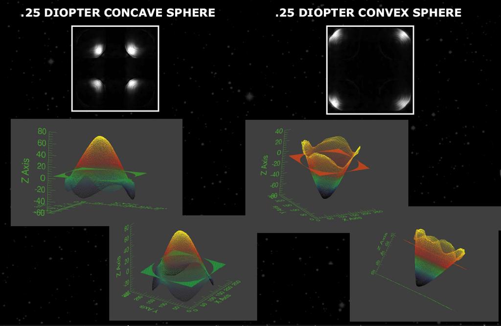
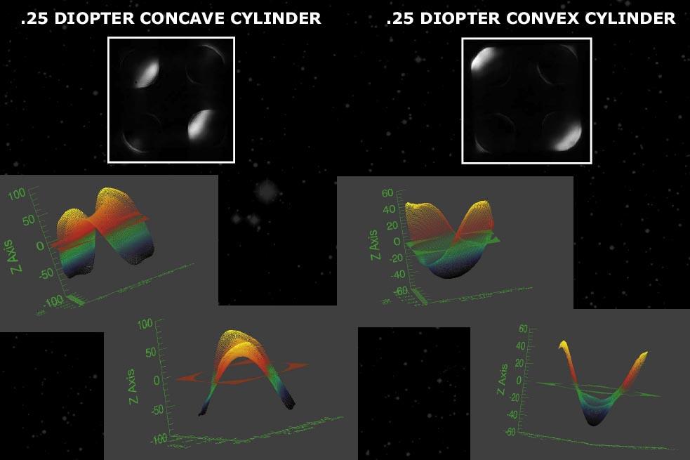
29 Simulation of curvature sensor response Wavefront: pure tilt Curvature sensor signal Credit: G. Chanan Page 29

30 Curvature sensor signal for astigmatism Credit: G. Chanan Page 30

31 Third order spherical aberration Credit: G. Chanan Page 31
32 Practical implementation of curvature sensing More intense Less intense Use oscillating membrane mirror (2 khz!) to vibrate rapidly between I + and I - extrafocal positions Measure intensity in each subaperture with an avalanche photodiode (only need one per subaperture!) Detects individual photons, no read noise, QE ~ 60% Can read out very fast with no noise penalty Page 32
33 Measurement error from curvature sensing Error of a single set of measurements is determined by photon statistics, since detector has NO read noise! 1 σ 2 cs = π 2 N ph θ b d λ where d = subaperture diameter and N ph is no. of photoelectrons per subaperture per sample period Error propagation when the wavefront is reconstructed numerically using a computer scales poorly with no. of subapertures N: (Error) curvature N, whereas (Error) Shack-Hartmann log N 2 Page 33
34 Question Think of as many pros and cons as you can for Shack-Hartmann sensing Curvature sensing Page 34
35 Advantages and disadvantages of curvature sensing Advantages: Lower noise can use fainter guide stars than S-H Fast readout can run AO system faster Can adjust amplitude of membrane mirror excursion as seeing conditions change. Affects sensitivity. Well matched to bimorph deformable mirror (both solve Laplace s equation), so less computation. Curvature systems appear to be less expensive. Disadvantages: Avalanche photodiodes can fail if too much light falls on them. They are bulky and expensive. Hard to use a large number of avalanche photodiodes. BUT recently available in arrays Page 35
36 Review of Shack-Hartmann geometry f Pupil plane Image plane Page 36

37 Pyramid sensing From Andrei Tokovinin s tutorial Image plane Pupil plane Page 37

38 Pyramid for the William Herschel Telescope s AO system Page 38

39 Schematic of pyramid sensor Credit: Iuliia Shatokhina et al. Page 39

40 Pyramid sensor reverses order of operations in a Shack-Hartmann sensor Page 40

41 Here s what a pyramidsensor meas t looks like Courtesy of Jess Johnson Page 41
42 Page 42
43 Page 43
44 Potential advantages of pyramid wavefront sensors Wavefront measurement error can be much lower Shack-Hartmann: size of spot limited to λ / d, where d is size of a sub-aperture and usually d ~ r 0 Pyramid: size of spot can be as small as λ / D, where D is size of whole telescope. So spot can be D/r 0 = times smaller than for Shack-Hartmann Measurement error (e.g. centroiding) is proportional to spot size/snr. Smaller spot = lower error. Avoids bad effects of charge diffusion in CCD detectors Fuzzes out edges of pixels. Pyramid doesn t mind as much as S-H. Page 44

45 Potential pyramid sensor advantages, continued Linear response over a larger dynamic range Naturally filters out high spatial frequency information that you can t correct anyway Page 45
46 Summary of main points Wavefront sensors in common use for astronomy measure intensity variations, deduce phase. Complementary. Shack-Hartmann Curvature sensors Curvature systems: cheaper, fewer degrees of freedom, scale more poorly to high no. of degrees of freedom, but can use fainter guide stars Shack-Hartmann systems excel at very large no. of degrees of freedom New kid on the block: pyramid sensors Very successful for fainter natural guide stars Page 46
Wavefront Sensing In Other Disciplines. 15 February 2003 Jerry Nelson, UCSC Wavefront Congress
 Wavefront Sensing In Other Disciplines 15 February 2003 Jerry Nelson, UCSC Wavefront Congress QuickTime and a Photo - JPEG decompressor are needed to see this picture. 15feb03 Nelson wavefront sensing
Wavefront sensing for adaptive optics
 Wavefront sensing for adaptive optics Brian Bauman, LLNL This work performed under the auspices of the U.S. Department of Energy by Lawrence Livermore National Laboratory under Contract DE-AC52-07NA27344.
MALA MATEEN. 1. Abstract
 IMPROVING THE SENSITIVITY OF ASTRONOMICAL CURVATURE WAVEFRONT SENSOR USING DUAL-STROKE CURVATURE: A SYNOPSIS MALA MATEEN 1. Abstract Below I present a synopsis of the paper: Improving the Sensitivity of
Wavefront sensing for adaptive optics
 Wavefront sensing for adaptive optics Richard Dekany Caltech Optical Observatories 2009 Thanks to: Acknowledgments Marcos van Dam original screenplay Brian Bauman adapted screenplay Contributors Richard
Adaptive Optics lectures
 Adaptive Optics lectures 2. Adaptive optics Invented in 1953 by H.Babcock Andrei Tokovinin 1 Plan General idea (open/closed loop) Wave-front sensing, its limitations Correctors (DMs) Control (spatial and
Adaptive Optics for LIGO
 Adaptive Optics for LIGO Justin Mansell Ginzton Laboratory LIGO-G990022-39-M Motivation Wavefront Sensor Outline Characterization Enhancements Modeling Projections Adaptive Optics Results Effects of Thermal
Aberrations and adaptive optics for biomedical microscopes
 Aberrations and adaptive optics for biomedical microscopes Martin Booth Department of Engineering Science And Centre for Neural Circuits and Behaviour University of Oxford Outline Rays, wave fronts and
3.0 Alignment Equipment and Diagnostic Tools:
 3.0 Alignment Equipment and Diagnostic Tools: Alignment equipment The alignment telescope and its use The laser autostigmatic cube (LACI) interferometer A pin -- and how to find the center of curvature
A Ground-based Sensor to Detect GEOs Without the Use of a Laser Guide-star
 A Ground-based Sensor to Detect GEOs Without the Use of a Laser Guide-star Mala Mateen Air Force Research Laboratory, Kirtland AFB, NM, 87117 Olivier Guyon Subaru Telescope, Hilo, HI, 96720 Michael Hart,
Ocular Shack-Hartmann sensor resolution. Dan Neal Dan Topa James Copland
 Ocular Shack-Hartmann sensor resolution Dan Neal Dan Topa James Copland Outline Introduction Shack-Hartmann wavefront sensors Performance parameters Reconstructors Resolution effects Spot degradation Accuracy
KAPAO: Design and Assembly of the Wavefront Sensor for an Adaptive Optics Instrument
 KAPAO: Design and Assembly of the Wavefront Sensor for an Adaptive Optics Instrument by Daniel Savino Contreras A thesis submitted in partial fulfillment for the degree of Bachelor of Arts in Physics and
1.6 Beam Wander vs. Image Jitter
 8 Chapter 1 1.6 Beam Wander vs. Image Jitter It is common at this point to look at beam wander and image jitter and ask what differentiates them. Consider a cooperative optical communication system that
12.4 Alignment and Manufacturing Tolerances for Segmented Telescopes
 330 Chapter 12 12.4 Alignment and Manufacturing Tolerances for Segmented Telescopes Similar to the JWST, the next-generation large-aperture space telescope for optical and UV astronomy has a segmented
Geometrical Optics for AO Claire Max UC Santa Cruz CfAO 2009 Summer School
 Geometrical Optics for AO Claire Max UC Santa Cruz CfAO 2009 Summer School Page 1 Some tools for active learning In-class conceptual questions will aim to engage you in more active learning and provide
Optimization of Existing Centroiding Algorithms for Shack Hartmann Sensor
 Proceeding of the National Conference on Innovative Computational Intelligence & Security Systems Sona College of Technology, Salem. Apr 3-4, 009. pp 400-405 Optimization of Existing Centroiding Algorithms
Paper Synopsis. Xiaoyin Zhu Nov 5, 2012 OPTI 521
 Paper Synopsis Xiaoyin Zhu Nov 5, 2012 OPTI 521 Paper: Active Optics and Wavefront Sensing at the Upgraded 6.5-meter MMT by T. E. Pickering, S. C. West, and D. G. Fabricant Abstract: This synopsis summarized
Wavefront control for highcontrast
 Wavefront control for highcontrast imaging Lisa A. Poyneer In the Spirit of Bernard Lyot: The direct detection of planets and circumstellar disks in the 21st century. Berkeley, CA, June 6, 2007 p Gemini
Observational Astronomy
 Observational Astronomy Instruments The telescope- instruments combination forms a tightly coupled system: Telescope = collecting photons and forming an image Instruments = registering and analyzing the
Effect of segmented telescope phasing errors on adaptive optics performance
 Effect of segmented telescope phasing errors on adaptive optics performance Marcos van Dam Flat Wavefronts Sam Ragland & Peter Wizinowich W.M. Keck Observatory Motivation Keck II AO / NIRC2 K-band Strehl
Proposed Adaptive Optics system for Vainu Bappu Telescope
 Proposed Adaptive Optics system for Vainu Bappu Telescope Essential requirements of an adaptive optics system Adaptive Optics is a real time wave front error measurement and correction system The essential
High contrast imaging lab
 High contrast imaging lab Ay122a, November 2016, D. Mawet Introduction This lab is an introduction to high contrast imaging, and in particular coronagraphy and its interaction with adaptive optics sytems.
Non-adaptive Wavefront Control
 OWL Phase A Review - Garching - 2 nd to 4 th Nov 2005 Non-adaptive Wavefront Control (Presented by L. Noethe) 1 Specific problems in ELTs and OWL Concentrate on problems which are specific for ELTs and,
Optical Components for Laser Applications. Günter Toesko - Laserseminar BLZ im Dezember
 Günter Toesko - Laserseminar BLZ im Dezember 2009 1 Aberrations An optical aberration is a distortion in the image formed by an optical system compared to the original. It can arise for a number of reasons
Lecture 4: Geometrical Optics 2. Optical Systems. Images and Pupils. Rays. Wavefronts. Aberrations. Outline
 Lecture 4: Geometrical Optics 2 Outline 1 Optical Systems 2 Images and Pupils 3 Rays 4 Wavefronts 5 Aberrations Christoph U. Keller, Leiden University, keller@strw.leidenuniv.nl Lecture 4: Geometrical
Why is There a Black Dot when Defocus = 1λ?
 Why is There a Black Dot when Defocus = 1λ? W = W 020 = a 020 ρ 2 When a 020 = 1λ Sag of the wavefront at full aperture (ρ = 1) = 1λ Sag of the wavefront at ρ = 0.707 = 0.5λ Area of the pupil from ρ =
Study of self-interference incoherent digital holography for the application of retinal imaging
 Study of self-interference incoherent digital holography for the application of retinal imaging Jisoo Hong and Myung K. Kim Department of Physics, University of South Florida, Tampa, FL, US 33620 ABSTRACT
Calibration of AO Systems
 Calibration of AO Systems Application to NAOS-CONICA and future «Planet Finder» systems T. Fusco, A. Blanc, G. Rousset Workshop Pueo Nu, may 2003 Département d Optique Théorique et Appliquée ONERA, Châtillon
Designing Adaptive Optics Systems
 Designing Adaptive Optics Systems Donald Gavel UCO/Lick Observatory Laboratory for Adaptive Optics Designing Adaptive Optics Systems Outline The design process AO systems taxonomy Commonalities and differences
WaveMaster IOL. Fast and Accurate Intraocular Lens Tester
 WaveMaster IOL Fast and Accurate Intraocular Lens Tester INTRAOCULAR LENS TESTER WaveMaster IOL Fast and accurate intraocular lens tester WaveMaster IOL is an instrument providing real time analysis of
Cardinal Points of an Optical System--and Other Basic Facts
 Cardinal Points of an Optical System--and Other Basic Facts The fundamental feature of any optical system is the aperture stop. Thus, the most fundamental optical system is the pinhole camera. The image
Open-loop performance of a high dynamic range reflective wavefront sensor
 Open-loop performance of a high dynamic range reflective wavefront sensor Jonathan R. Andrews 1, Scott W. Teare 2, Sergio R. Restaino 1, David Wick 3, Christopher C. Wilcox 1, Ty Martinez 1 Abstract: Sandia
GPI INSTRUMENT PAGES
 GPI INSTRUMENT PAGES This document presents a snapshot of the GPI Instrument web pages as of the date of the call for letters of intent. Please consult the GPI web pages themselves for up to the minute
PROCEEDINGS OF SPIE. Measurement of low-order aberrations with an autostigmatic microscope
 PROCEEDINGS OF SPIE SPIEDigitalLibrary.org/conference-proceedings-of-spie Measurement of low-order aberrations with an autostigmatic microscope William P. Kuhn Measurement of low-order aberrations with
AY122A - Adaptive Optics Lab
 AY122A - Adaptive Optics Lab Purpose In this lab, after an introduction to turbulence and adaptive optics for astronomy, you will get to experiment first hand the three main components of an adaptive optics
ECEN 4606, UNDERGRADUATE OPTICS LAB
 ECEN 4606, UNDERGRADUATE OPTICS LAB Lab 2: Imaging 1 the Telescope Original Version: Prof. McLeod SUMMARY: In this lab you will become familiar with the use of one or more lenses to create images of distant
Optical System Design
 Phys 531 Lecture 12 14 October 2004 Optical System Design Last time: Surveyed examples of optical systems Today, discuss system design Lens design = course of its own (not taught by me!) Try to give some
WaveMaster IOL. Fast and accurate intraocular lens tester
 WaveMaster IOL Fast and accurate intraocular lens tester INTRAOCULAR LENS TESTER WaveMaster IOL Fast and accurate intraocular lens tester WaveMaster IOL is a new instrument providing real time analysis
Ron Liu OPTI521-Introductory Optomechanical Engineering December 7, 2009
 Synopsis of METHOD AND APPARATUS FOR IMPROVING VISION AND THE RESOLUTION OF RETINAL IMAGES by David R. Williams and Junzhong Liang from the US Patent Number: 5,777,719 issued in July 7, 1998 Ron Liu OPTI521-Introductory
NGAO NGS WFS design review
 NGAO NGS WFS design review Caltech Optical 1 st April2010 1 Presentation outline Requirements (including modes of operation and motion control) Introduction NGSWFS input feed (performance of the triplet
Lecture 2: Geometrical Optics. Geometrical Approximation. Lenses. Mirrors. Optical Systems. Images and Pupils. Aberrations.
 Lecture 2: Geometrical Optics Outline 1 Geometrical Approximation 2 Lenses 3 Mirrors 4 Optical Systems 5 Images and Pupils 6 Aberrations Christoph U. Keller, Leiden Observatory, keller@strw.leidenuniv.nl
Shack Hartmann Sensor Based on a Low-Aperture Off-Axis Diffraction Lens Array
 ISSN 8756-699, Optoelectronics, Instrumentation and Data Processing, 29, Vol. 45, No. 2, pp. 6 7. c Allerton Press, Inc., 29. Original Russian Text c V.P. Lukin, N.N. Botygina, O.N. Emaleev, V.P. Korol
Shaping light in microscopy:
 Shaping light in microscopy: Adaptive optical methods and nonconventional beam shapes for enhanced imaging Martí Duocastella planet detector detector sample sample Aberrated wavefront Beamsplitter Adaptive
Improving techniques for Shack-Hartmann wavefront sensing: dynamic-range and frame rate
 Improving techniques for Shack-Hartmann wavefront sensing: dynamic-range and frame rate Takao Endo, Yoshichika Miwa, Jiro Suzuki and Toshiyuki Ando Information Technology R&D Center, Mitsubishi Electric
Phys 531 Lecture 9 30 September 2004 Ray Optics II. + 1 s i. = 1 f
 Phys 531 Lecture 9 30 September 2004 Ray Optics II Last time, developed idea of ray optics approximation to wave theory Introduced paraxial approximation: rays with θ 1 Will continue to use Started disussing
AgilEye Manual Version 2.0 February 28, 2007
 AgilEye Manual Version 2.0 February 28, 2007 1717 Louisiana NE Suite 202 Albuquerque, NM 87110 (505) 268-4742 support@agiloptics.com 2 (505) 268-4742 v. 2.0 February 07, 2007 3 Introduction AgilEye Wavefront
Multi aperture coherent imaging IMAGE testbed
 Multi aperture coherent imaging IMAGE testbed Nick Miller, Joe Haus, Paul McManamon, and Dave Shemano University of Dayton LOCI Dayton OH 16 th CLRC Long Beach 20 June 2011 Aperture synthesis (part 1 of
The Extreme Adaptive Optics test bench at CRAL
 The Extreme Adaptive Optics test bench at CRAL Maud Langlois, Magali Loupias, Christian Delacroix, E. Thiébaut, M. Tallon, Louisa Adjali, A. Jarno 1 XAO challenges Strehl: 0.7
Puntino. Shack-Hartmann wavefront sensor for optimizing telescopes. The software people for optics
 Puntino Shack-Hartmann wavefront sensor for optimizing telescopes 1 1. Optimize telescope performance with a powerful set of tools A finely tuned telescope is the key to obtaining deep, high-quality astronomical
MODULAR ADAPTIVE OPTICS TESTBED FOR THE NPOI
 MODULAR ADAPTIVE OPTICS TESTBED FOR THE NPOI Jonathan R. Andrews, Ty Martinez, Christopher C. Wilcox, Sergio R. Restaino Naval Research Laboratory, Remote Sensing Division, Code 7216, 4555 Overlook Ave
Kolmogorov Turbulence, completed; then Geometrical Optics for AO
 Kolmogorov Turbulence, completed; then Geometrical Optics for AO Claire Max ASTR 289, UCSC January 19, 2016 Page 1 Finish up discussion of Kolmogorov Turbulence from previous lecture Page 2 Structure function
Segmented deformable mirrors for Ground layer Adaptive Optics
 Segmented deformable mirrors for Ground layer Adaptive Optics Edward Kibblewhite, University of Chicago Adaptive Photonics LLC Ground Layer AO Shack Hartmann Images of 5 guide stars in Steward Observatory
Adaptive Optics Overview (Astronomical)
") Adaptive Optics Overview (Astronomical) Richard Myers Durham University William Herschel Telescope with GLAS Rayleigh Laser Guide Star Photo: Tibor Agocs, Isaac Newton Group of Telescopes Outline Generic
Adaptive Optics Overview (Astronomical) Richard Myers Durham University William Herschel Telescope with GLAS Rayleigh Laser Guide Star Photo: Tibor Agocs, Isaac Newton Group of Telescopes Outline Generic
Effect of segmented telescope phasing errors on adaptive optics performance
 Effect of segmented telescope phasing errors on adaptive optics performance Marcos A. van Dam a, Sam Ragland b, and Peter L. Wizinowich b a Flat Wavefronts, 21 Lascelles Street, Christchurch 8022, New
Modeling the multi-conjugate adaptive optics system of the E-ELT. Laura Schreiber Carmelo Arcidiacono Giovanni Bregoli
 Modeling the multi-conjugate adaptive optics system of the E-ELT Laura Schreiber Carmelo Arcidiacono Giovanni Bregoli MAORY E-ELT Multi Conjugate Adaptive Optics Relay Wavefront sensing based on 6 (4)
Wavefront sensing by an aperiodic diffractive microlens array
 Wavefront sensing by an aperiodic diffractive microlens array Lars Seifert a, Thomas Ruppel, Tobias Haist, and Wolfgang Osten a Institut für Technische Optik, Universität Stuttgart, Pfaffenwaldring 9,
Potential benefits of freeform optics for the ELT instruments. J. Kosmalski
 Potential benefits of freeform optics for the ELT instruments J. Kosmalski Freeform Days, 12-13 th October 2017 Summary Introduction to E-ELT intruments Freeform design for MAORY LGS Free form design for
Focal Plane and non-linear Curvature Wavefront Sensing for High Contrast Coronagraphic Adaptive Optics Imaging
 Focal Plane and non-linear Curvature Wavefront Sensing for High Contrast Coronagraphic Adaptive Optics Imaging Olivier Guyon Subaru Telescope 640 N. A'ohoku Pl. Hilo, HI 96720 USA Abstract Wavefronts can
Metrology and Sensing
 Metrology and Sensing Lecture 7: Wavefront sensors 2016-11-29 Herbert Gross Winter term 2016 www.iap.uni-jena.de 2 Preliminary Schedule No Date Subject Detailed Content 1 18.10. Introduction Introduction,
IAC-08-C1.8.5 OPTICAL BEAM CONTROL FOR IMAGING SPACECRAFT WITH LARGE APERTURES
 IAC-08-C1.8.5 OPTICAL BEAM CONTROL FOR IMAGING SPACECRAFT WITH LARGE APERTURES Jae Jun Kim Research Assistant Professor, jki1@nps.edu Anne Marie Johnson NRC Research Associate, ajohnson@nps.edu Brij N.
Reference and User Manual May, 2015 revision - 3
 Reference and User Manual May, 2015 revision - 3 Innovations Foresight 2015 - Powered by Alcor System 1 For any improvement and suggestions, please contact customerservice@innovationsforesight.com Some
Using Stock Optics. ECE 5616 Curtis
 Using Stock Optics What shape to use X & Y parameters Please use achromatics Please use camera lens Please use 4F imaging systems Others things Data link Stock Optics Some comments Advantages Time and
Development of a Low-order Adaptive Optics System at Udaipur Solar Observatory
 J. Astrophys. Astr. (2008) 29, 353 357 Development of a Low-order Adaptive Optics System at Udaipur Solar Observatory A. R. Bayanna, B. Kumar, R. E. Louis, P. Venkatakrishnan & S. K. Mathew Udaipur Solar
Explanation of Aberration and Wavefront
 Explanation of Aberration and Wavefront 1. What Causes Blur? 2. What is? 4. What is wavefront? 5. Hartmann-Shack Aberrometer 6. Adoption of wavefront technology David Oh 1. What Causes Blur? 2. What is?
PYRAMID WAVEFRONT SENSOR PERFORMANCE WITH LASER GUIDE STARS
 Florence, Italy. Adaptive May 2013 Optics for Extremely Large Telescopes III ISBN: 978-88-908876-0-4 DOI: 10.12839/AO4ELT3.13138 PYRAMID WAVEFRONT SENSOR PERFORMANCE WITH LASER GUIDE STARS Fernando Quirós-Pacheco
Subject headings: turbulence -- atmospheric effects --techniques: interferometric -- techniques: image processing
 Direct 75 Milliarcsecond Images from the Multiple Mirror Telescope with Adaptive Optics M. Lloyd-Hart, R. Dekany, B. McLeod, D. Wittman, D. Colucci, D. McCarthy, and R. Angel Steward Observatory, University
DESIGN NOTE: DIFFRACTION EFFECTS
 NASA IRTF / UNIVERSITY OF HAWAII Document #: TMP-1.3.4.2-00-X.doc Template created on: 15 March 2009 Last Modified on: 5 April 2010 DESIGN NOTE: DIFFRACTION EFFECTS Original Author: John Rayner NASA Infrared
Chapter 18 Optical Elements
 Chapter 18 Optical Elements GOALS When you have mastered the content of this chapter, you will be able to achieve the following goals: Definitions Define each of the following terms and use it in an operational
Deep- Space Optical Communication Link Requirements
 Deep- Space Optical Communication Link Requirements Professor Chester S. Gardner Department of Electrical and Computer Engineering University of Illinois cgardner@illinois.edu Link Equation: For a free-
CHARA AO Calibration Process
 CHARA AO Calibration Process Judit Sturmann CHARA AO Project Overview Phase I. Under way WFS on telescopes used as tip-tilt detector Phase II. Not yet funded WFS and large DM in place of M4 on telescopes
Design and manufacture of large aperture wavefront sensor
 Design and manufacture of large aperture wavefront sensor Rich Hutchin a, Oberdan Otto a, Alan Wertheimer b a Optical Physics Company, 66 Agoura Road, Calabasas, CA USA 93 b Eastman Kodak Company, 7 St.
Comparative Performance of a 3-Sided and 4-Sided Pyramid Wavefront Sensor. HartSCI LLC, 2555 N. Coyote Dr. #114, Tucson, AZ
 Comparative Performance of a 3-Sided and 4-Sided Pyramid Wavefront Sensor Johanan L. Codona 3, Michael Hart 1,2, Lauren H. Schatz 2, and Mala Mateen 3 1 HartSCI LLC, 2555 N. Coyote Dr. #114, Tucson, AZ
Design of the cryo-optical test of the Planck reflectors
 Design of the cryo-optical test of the Planck reflectors S. Roose, A. Cucchiaro & D. de Chambure* Centre Spatial de Liège, Avenue du Pré-Aily, B-4031 Angleur-Liège, Belgium *ESTEC, Planck project, Keplerlaan
GENERALISED PHASE DIVERSITY WAVEFRONT SENSING 1 ABSTRACT 1. INTRODUCTION
 GENERALISED PHASE DIVERSITY WAVEFRONT SENSING 1 Heather I. Campbell Sijiong Zhang Aurelie Brun 2 Alan H. Greenaway Heriot-Watt University, School of Engineering and Physical Sciences, Edinburgh EH14 4AS
CHARA Collaboration Review New York 2007 CHARA Telescope Alignment
 CHARA Telescope Alignment By Laszlo Sturmann Mersenne (Cassegrain type) Telescope M2 140 mm R= 625 mm k = -1 M1/M2 provides an afocal optical system 1 m input beam and 0.125 m collimated output beam Aplanatic
Bruce Macintosh for the GPI team Presented at the Spirit of Lyot conference June 7, 2007
 This work was performed under the auspices of the U.S. Department of Energy by University of California, Lawrence Livermore National Laboratory under Contract W-7405-Eng-48. Bruce Macintosh for the GPI
Physics 3340 Spring Fourier Optics
 Physics 3340 Spring 011 Purpose Fourier Optics In this experiment we will show how the Fraunhofer diffraction pattern or spatial Fourier transform of an object can be observed within an optical system.
Design of a digital holographic interferometer for the. ZaP Flow Z-Pinch
 Design of a digital holographic interferometer for the M. P. Ross, U. Shumlak, R. P. Golingo, B. A. Nelson, S. D. Knecht, M. C. Hughes, R. J. Oberto University of Washington, Seattle, USA Abstract The
Lecture 15: Fraunhofer diffraction by a circular aperture
 Lecture 15: Fraunhofer diffraction by a circular aperture Lecture aims to explain: 1. Diffraction problem for a circular aperture 2. Diffraction pattern produced by a circular aperture, Airy rings 3. Importance
The Wavefront Control System for the Keck Telescope
 UCRL-JC-130919 PREPRINT The Wavefront Control System for the Keck Telescope J.M. Brase J. An K. Avicola B.V. Beeman D.T. Gavel R. Hurd B. Johnston H. Jones T. Kuklo C.E. Max S.S. Olivier K.E. Waltjen J.
Figure 7 Dynamic range expansion of Shack- Hartmann sensor using a spatial-light modulator
 Figure 4 Advantage of having smaller focal spot on CCD with super-fine pixels: Larger focal point compromises the sensitivity, spatial resolution, and accuracy. Figure 1 Typical microlens array for Shack-Hartmann
APPLICATION NOTE
 THE PHYSICS BEHIND TAG OPTICS TECHNOLOGY AND THE MECHANISM OF ACTION OF APPLICATION NOTE 12-001 USING SOUND TO SHAPE LIGHT Page 1 of 6 Tutorial on How the TAG Lens Works This brief tutorial explains the
MAORY E-ELT MCAO module project overview
 MAORY E-ELT MCAO module project overview Emiliano Diolaiti Istituto Nazionale di Astrofisica Osservatorio Astronomico di Bologna On behalf of the MAORY Consortium AO4ELT3, Firenze, 27-31 May 2013 MAORY
Lens Design I. Lecture 5: Advanced handling I Herbert Gross. Summer term
 Lens Design I Lecture 5: Advanced handling I 2018-05-17 Herbert Gross Summer term 2018 www.iap.uni-jena.de 2 Preliminary Schedule - Lens Design I 2018 1 12.04. Basics 2 19.04. Properties of optical systems
Payload Configuration, Integration and Testing of the Deformable Mirror Demonstration Mission (DeMi) CubeSat
 CubeSat") SSC18-VIII-05 Payload Configuration, Integration and Testing of the Deformable Mirror Demonstration Mission (DeMi) CubeSat Jennifer Gubner Wellesley College, Massachusetts Institute of Technology 21 Wellesley
SSC18-VIII-05 Payload Configuration, Integration and Testing of the Deformable Mirror Demonstration Mission (DeMi) CubeSat Jennifer Gubner Wellesley College, Massachusetts Institute of Technology 21 Wellesley
Implementation of a waveform recovery algorithm on FPGAs using a zonal method (Hudgin)
") 1st AO4ELT conference, 07010 (2010) DOI:10.1051/ao4elt/201007010 Owned by the authors, published by EDP Sciences, 2010 Implementation of a waveform recovery algorithm on FPGAs using a zonal method (Hudgin)
1st AO4ELT conference, 07010 (2010) DOI:10.1051/ao4elt/201007010 Owned by the authors, published by EDP Sciences, 2010 Implementation of a waveform recovery algorithm on FPGAs using a zonal method (Hudgin)
AgilOptics mirrors increase coupling efficiency into a 4 µm diameter fiber by 750%.
 Application Note AN004: Fiber Coupling Improvement Introduction AgilOptics mirrors increase coupling efficiency into a 4 µm diameter fiber by 750%. Industrial lasers used for cutting, welding, drilling,
INTRODUCTION THIN LENSES. Introduction. given by the paraxial refraction equation derived last lecture: Thin lenses (19.1) = 1. Double-lens systems
 = 1. Double-lens systems") Chapter 9 OPTICAL INSTRUMENTS Introduction Thin lenses Double-lens systems Aberrations Camera Human eye Compound microscope Summary INTRODUCTION Knowledge of geometrical optics, diffraction and interference,
Chapter 9 OPTICAL INSTRUMENTS Introduction Thin lenses Double-lens systems Aberrations Camera Human eye Compound microscope Summary INTRODUCTION Knowledge of geometrical optics, diffraction and interference,
2.2 Wavefront Sensor Design. Lauren H. Schatz, Oli Durney, Jared Males
 Page: 1 of 8 Lauren H. Schatz, Oli Durney, Jared Males 1 Pyramid Wavefront Sensor Overview The MagAO-X system uses a pyramid wavefront sensor (PWFS) for high order wavefront sensing. The wavefront sensor
Chapter 34 The Wave Nature of Light; Interference. Copyright 2009 Pearson Education, Inc.
 Chapter 34 The Wave Nature of Light; Interference 34-7 Luminous Intensity The intensity of light as perceived depends not only on the actual intensity but also on the sensitivity of the eye at different
Handbook of Optical Systems
 Handbook of Optical Systems Volume 5: Metrology of Optical Components and Systems von Herbert Gross, Bernd Dörband, Henriette Müller 1. Auflage Handbook of Optical Systems Gross / Dörband / Müller schnell
DESIGNING AND IMPLEMENTING AN ADAPTIVE OPTICS SYSTEM FOR THE UH HOKU KE`A OBSERVATORY ABSTRACT
 DESIGNING AND IMPLEMENTING AN ADAPTIVE OPTICS SYSTEM FOR THE UH HOKU KE`A OBSERVATORY University of Hawai`i at Hilo Alex Hedglen ABSTRACT The presented project is to implement a small adaptive optics system
EE119 Introduction to Optical Engineering Fall 2009 Final Exam. Name:
 EE119 Introduction to Optical Engineering Fall 2009 Final Exam Name: SID: CLOSED BOOK. THREE 8 1/2 X 11 SHEETS OF NOTES, AND SCIENTIFIC POCKET CALCULATOR PERMITTED. TIME ALLOTTED: 180 MINUTES Fundamental
Reflectors vs. Refractors
 1 Telescope Types - Telescopes collect and concentrate light (which can then be magnified, dispersed as a spectrum, etc). - In the end it is the collecting area that counts. - There are two primary telescope
A prototype of the Laser Guide Stars wavefront sensor for the E-ELT multi-conjugate adaptive optics module
 1st AO4ELT conference, 05020 (2010) DOI:10.1051/ao4elt/201005020 Owned by the authors, published by EDP Sciences, 2010 A prototype of the Laser Guide Stars wavefront sensor for the E-ELT multi-conjugate
Shack Hartmann sensor improvement using optical binning
 Shack Hartmann sensor improvement using optical binning Alastair Basden,* Deli Geng, Dani Guzman, Tim Morris, Richard Myers, and Chris Saunter Department of Physics, South Road, Durham, DH1 3LE, UK *Corresponding
Study on Imaging Quality of Water Ball Lens
 2017 2nd International Conference on Mechatronics and Information Technology (ICMIT 2017) Study on Imaging Quality of Water Ball Lens Haiyan Yang1,a,*, Xiaopan Li 1,b, 1,c Hao Kong, 1,d Guangyang Xu and1,eyan
On-sky validation of LIFT on GeMS
 Florence, Italy. May 2013 ISBN: 978-88-908876-0-4 DOI: 10.12839/AO4ELT3.13355 On-sky validation of LIFT on GeMS Cédric Plantet 1a, Serge Meimon 1, Jean-Marc Conan 1, Benoit Neichel 2, and Thierry Fusco
Optical Design of an Off-axis Five-mirror-anastigmatic Telescope for Near Infrared Remote Sensing
 Journal of the Optical Society of Korea Vol. 16, No. 4, December 01, pp. 343-348 DOI: http://dx.doi.org/10.3807/josk.01.16.4.343 Optical Design of an Off-axis Five-mirror-anastigmatic Telescope for Near
EE119 Introduction to Optical Engineering Spring 2003 Final Exam. Name:
 EE119 Introduction to Optical Engineering Spring 2003 Final Exam Name: SID: CLOSED BOOK. THREE 8 1/2 X 11 SHEETS OF NOTES, AND SCIENTIFIC POCKET CALCULATOR PERMITTED. TIME ALLOTTED: 180 MINUTES Fundamental