CHAPTER 1 Optical Aberrations
|
|
|
- Hector Richards
- 5 years ago
- Views:
Transcription
1 CHAPTER 1 Optical Aberrations 1.1 INTRODUCTION This chapter starts with the concepts of aperture stop and entrance and exit pupils of an optical imaging system. Certain special rays, such as the chief and the marginal, are defined. The wave aberration associated with a ray is defined and its relationship to the corresponding transverse ray aberration is given. Representations of wavefront defocus and tilt aberrations are given. We introduce different forms of the primary aberration function of a rotationally symmetric system. How this function changes as the aperture stop of the system is moved from one position to another is discussed. The primary aberration function for the simplest imaging system, namely, a single spherical refracting surface, is given for an arbitrary position of the aperture stop. Finally, we outline a procedure by which the aberration function of a multielement system may be calculated. This procedure is utilized in later chapters, for example, to calculate the aberration of a thin lens (Chapter 2) and a plane-parallel plate (Chapter 3). This chapter forms the basis of Part I on geometrical optics. 1.2 OPTICAL IMAGING An optical imaging system consists of a series of refracting and/or reflecting surfaces. The surfaces refract or reflect light rays from an object to form its image. The image obtained according to geometrical optics in the Gaussian approximation, i.e., according to Snell's law in which the sines of the angles are replaced by the angles, is called the Gaussian image. The Gaussian approximation and the Gaussian image are often referred to as the paraxial approximation and the paraxial image, respectively. We assume that the surfaces are rotationally symmetric about a common axis called the optical axis (OA). Figure 1-1 illustrates the imaging of an on-axis point object P 0 and an off-axis point object P, respectively, by an optical system consisting of two thin lenses. (For definition of a thin lens, see Section 2.2.) P and P 0 are the corresponding Gaussian image points. An object and its image are called conjugates of each other, i.e., if one of the two conjugates is an object, the other is its image. An aperture in the system that physically limits the solid angle of the rays from a point object the most is called the aperture stop (AS). For an extended (i.e., a nonpoint) object, it is customary to consider the aperture stop as the limiting aperture for the axial point object, and to determine vignetting, or blocking of some rays, by this stop for offaxis object points. The object is assumed to be placed to the left of the system so that initially light travels from left to right. The image of the stop by surfaces that precede it in the sense of light propagation, i.e., by surfaces that lie between it and the object, is called the entrance pupil (EnP). When observed from the object side, the entrance pupil appears to limit the rays entering the system to form the image of the object. Similarly, the image of the aperture stop by surfaces that follow it, i.e., by surfaces that lie between it and the 1
2 2 OPTICAL ABERRATIONS ExP L 1 EnP AS L2 MR 0 P 0 OA CR 0 B 02 A 01 A 02 P 0 MR 0 B 01 (a) ExP L 1 AS EnP L2 C 2 B 2 P P 0 OA MR CR MR A 1 B 1 C 1 A 2 P 0 P (b) Figure 1-1. (a) Imaging of an on-axis point object P 0 by an optical imaging system consisting of two lenses L 1 and L 2. OA is the optical axis. The Gaussian image is at P 0. AS is the aperture stop; its image by L 1 is the entrance pupil EnP, and its image by L 2 is the exit pupil ExP. CR 0 is the axial chief ray, and MR 0 is the axial marginal ray. (b) Imaging of an off-axis point object P. The Gaussian image is at P. CR is the off-axis chief ray, MR is the off-axis marginal ray. image, is called the exit pupil (ExP). The object rays reaching its image appear to be limited by the exit pupil. Since the entrance and exit pupils are images of the stop by the surfaces that precede and follow it, respectively, the two pupils are conjugates of each other for the whole system; i.e., if one pupil is considered as the object, the other is its image formed by the system.
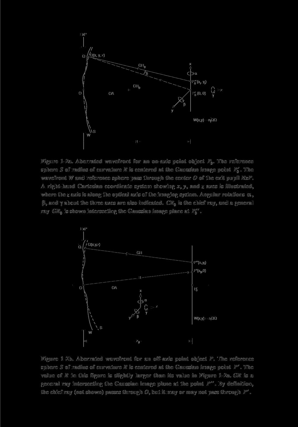
3 1.3 Wave and Ray Aberrations 3 An object ray passing through the center of the aperture stop and appearing to pass through the centers of the entrance and exit pupils is called the chief (or the principal) ray (CR). An object ray passing through the edge of the aperture stop is called a marginal ray (MR). The rays lying between the center and the edge of the aperture, and, therefore, appearing to lie between the center and edge of the entrance and exit pupils, are called zonal rays. It is possible that the stop of a system may also be its entrance and/or exit pupil. For example, a stop placed to the left of a lens is also its entrance pupil. Similarly, a stop placed to the right of a lens is also its exit pupil. Finally, a stop placed at a single thin lens is both its entrance and exit pupils. 1.3 WAVE AND RAY ABERRATIONS In this section, we define the wave aberration associated with a ray and relate it to its transverse ray aberration in an image plane. The optical path length of a ray in a medium of refractive index n is equal to n times its geometrical path length. If rays from a point object are traced through the system and up to the exit pupil such that each one travels an optical path length equal to that of the chief ray, the surface passing through their end points is called the system wavefront for the point object under consideration. If the wavefront is spherical with its center of curvature at the Gaussian image point, we say that the Gaussian image is perfect. If, however, the wavefront deviates from this Gaussian spherical wavefront, we say that the Gaussian image is aberrated. The optical deviation (i.e., geometrical deviations times the refractive index n of the image space) of the wavefront along a certain ray from the Gaussian spherical wavefront is called the wave aberration of that ray. It represents the difference between the optical path lengths of the ray under consideration and the chief ray in traveling from the point object to the reference sphere. Accordingly, the wave aberration associated with the chief ray is zero. The wave aberration associated with a ray is positive if it has to travel an extra optical path length, compared to the chief ray, in order to reach the Gaussian spherical wavefront. The Gaussian spherical wavefront is also called the Gaussian reference sphere. Figures 1-2a and 1-2b illustrate the reference sphere S and the aberrated wavefront W for on- and off-axis point objects whose Gaussian images lie at P 0 and P, respectively. The coordinate system is also illustrated in these figures. We choose a right-hand coordinate system such that the optical axis lies along the z axis. The object, entrance pupil, exit pupil, and the Gaussian image lie in mutually parallel planes that are perpendicular to this axis, with their origins lying along the axis. We assume that a point object such as P lies along the x axis. The zx plane containing the point object and the optical axis is called the tangential or the meridional plane. The Gaussian image P lying in the Gaussian image plane along its x axis also lies in the tangential plane. This may be seen by a consideration of a tangential object ray and Snell's law according to which the incident and refracted or reflected rays at a surface lie in the same plane. The chief ray
4 4 OPTICAL ABERRATIONS
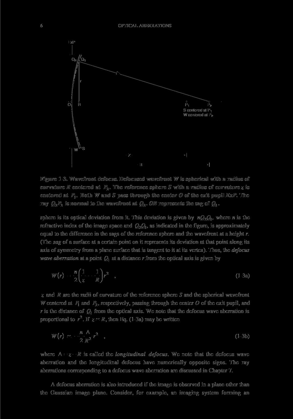
5 1.4 Defocus Aberration 5 always lies in the tangential plane. The plane normal to the tangential plane but containing the chief ray is called the sagittal plane. As the chief ray bends when it is refracted or reflected by an optical surface, so does the sagittal plane. Consider an image ray such as GR in Figure 1-2b passing through a point Q with coordinates (x, y, z) on the reference sphere of radius of curvature R centered at the image point. We let W(x, y) represent its wave aberration nqq, since z is related to x and y by virtue of Q being on the reference sphere. It can be shown that the ray intersects the Gaussian image plane at a point P whose coordinates with respect to the Gaussian image point P are approximately given by R Ê W W ˆ ( xi, yi ) = Á,. (1-1) n Ë x y [Equation (1-1) has been derived by Mahajan, Born and Wolf, and Welford. However, Welford uses a sign convention for the wave aberration that is opposite to ours.] The displacement PP 0 0 in Figure 1-2a (or PP in Figure 1-2b) of a ray from the Gaussian image point is called its geometrical or transverse ray aberration, and its coordinates ( xi, yi ) in the Gaussian image plane relative to the Gaussian image point are called its ray aberration components. Since a ray is normal to a wavefront, the ray aberration depends on the shape of the wavefront and, therefore, on its geometrical path difference from the reference sphere. The division of W by n in Eq. (1-1) converts the optical path length difference into geometrical path length difference. When an image is formed in free space, as is often the case in practice, then n = 1. The angle d ~ PP 0 0 R between the ideal ray QP 0 and the actual ray QP 0 is called the angular ray aberration. The distribution of rays from a point object in an image plane is called the ray spot. (Such diagrams are discussed in Chapter 7.) When the wavefront is spherical with its center of curvature at the Gaussian image point, then the wave and ray aberrations are zero. In that case, all of the object rays transmitted by the system pass through the Gaussian image point, and the image is perfect. We shall refer to W ( x, y) as the wave at a projected point ( x, y) in the plane of the exit pupil. If ( r, q) represent the corresponding polar coordinates, they are related to the rectangular coordinates according to ( ) = ( ) x, y r cos q, sin q. (1-2) 1.4 DEFOCUS ABERRATION We now discuss defocus wave aberration of a system and relate it to its longitudinal defocus. Consider an imaging system for which the Gaussian image of a point object is located at P 1. As indicated in Figure 1-3, let the wavefront for this point object be spherical with a center of curvature at P 2 (due to field curvature discussed in Section 1.6) such that P 2 lies on the line OP, joining the center 0 of the exit pupil and the Gaussian image point P 1. The aberration of the wavefront with respect to the Gaussian reference
6
Lecture 4: Geometrical Optics 2. Optical Systems. Images and Pupils. Rays. Wavefronts. Aberrations. Outline
 Lecture 4: Geometrical Optics 2 Outline 1 Optical Systems 2 Images and Pupils 3 Rays 4 Wavefronts 5 Aberrations Christoph U. Keller, Leiden University, keller@strw.leidenuniv.nl Lecture 4: Geometrical
Exam Preparation Guide Geometrical optics (TN3313)
") Exam Preparation Guide Geometrical optics (TN3313) Lectures: September - December 2001 Version of 21.12.2001 When preparing for the exam, check on Blackboard for a possible newer version of this guide.
Exam Preparation Guide Geometrical optics (TN3313) Lectures: September - December 2001 Version of 21.12.2001 When preparing for the exam, check on Blackboard for a possible newer version of this guide.
Introductions to aberrations OPTI 517
 Introductions to aberrations OPTI 517 Lecture 11 Spherical aberration Meridional and sagittal ray fans Spherical aberration 0.25 wave f/10; f=100 mm; wave=0.0005 mm Spherical aberration 0.5 wave f/10;
GEOMETRICAL OPTICS AND OPTICAL DESIGN
 GEOMETRICAL OPTICS AND OPTICAL DESIGN Pantazis Mouroulis Associate Professor Center for Imaging Science Rochester Institute of Technology John Macdonald Senior Lecturer Physics Department University of
Advanced Lens Design
 Advanced Lens Design Lecture 3: Aberrations I 214-11-4 Herbert Gross Winter term 214 www.iap.uni-jena.de 2 Preliminary Schedule 1 21.1. Basics Paraxial optics, imaging, Zemax handling 2 28.1. Optical systems
OPTICAL IMAGING AND ABERRATIONS
 OPTICAL IMAGING AND ABERRATIONS PARTI RAY GEOMETRICAL OPTICS VIRENDRA N. MAHAJAN THE AEROSPACE CORPORATION AND THE UNIVERSITY OF SOUTHERN CALIFORNIA SPIE O P T I C A L E N G I N E E R I N G P R E S S A
Waves & Oscillations
 Physics 42200 Waves & Oscillations Lecture 33 Geometric Optics Spring 2013 Semester Matthew Jones Aberrations We have continued to make approximations: Paraxial rays Spherical lenses Index of refraction
INTRODUCTION TO ABERRATIONS IN OPTICAL IMAGING SYSTEMS
 INTRODUCTION TO ABERRATIONS IN OPTICAL IMAGING SYSTEMS JOSE SASIÄN University of Arizona ШШ CAMBRIDGE Щ0 UNIVERSITY PRESS Contents Preface Acknowledgements Harold H. Hopkins Roland V. Shack Symbols 1 Introduction
Geometric optics & aberrations
 Geometric optics & aberrations Department of Astrophysical Sciences University AST 542 http://www.northerneye.co.uk/ Outline Introduction: Optics in astronomy Basics of geometric optics Paraxial approximation
Performance Factors. Technical Assistance. Fundamental Optics
 Performance Factors After paraxial formulas have been used to select values for component focal length(s) and diameter(s), the final step is to select actual lenses. As in any engineering problem, this
Lecture 2: Geometrical Optics. Geometrical Approximation. Lenses. Mirrors. Optical Systems. Images and Pupils. Aberrations.
 Lecture 2: Geometrical Optics Outline 1 Geometrical Approximation 2 Lenses 3 Mirrors 4 Optical Systems 5 Images and Pupils 6 Aberrations Christoph U. Keller, Leiden Observatory, keller@strw.leidenuniv.nl
CHAPTER 33 ABERRATION CURVES IN LENS DESIGN
 CHAPTER 33 ABERRATION CURVES IN LENS DESIGN Donald C. O Shea Georgia Institute of Technology Center for Optical Science and Engineering and School of Physics Atlanta, Georgia Michael E. Harrigan Eastman
Sequential Ray Tracing. Lecture 2
 Sequential Ray Tracing Lecture 2 Sequential Ray Tracing Rays are traced through a pre-defined sequence of surfaces while travelling from the object surface to the image surface. Rays hit each surface once
Lecture 2: Geometrical Optics. Geometrical Approximation. Lenses. Mirrors. Optical Systems. Images and Pupils. Aberrations.
 Lecture 2: Geometrical Optics Outline 1 Geometrical Approximation 2 Lenses 3 Mirrors 4 Optical Systems 5 Images and Pupils 6 Aberrations Christoph U. Keller, Leiden Observatory, keller@strw.leidenuniv.nl
Opti 415/515. Introduction to Optical Systems. Copyright 2009, William P. Kuhn
 Opti 415/515 Introduction to Optical Systems 1 Optical Systems Manipulate light to form an image on a detector. Point source microscope Hubble telescope (NASA) 2 Fundamental System Requirements Application
 Telecentric Imaging Object space telecentricity stop source: edmund optics The 5 classical Seidel Aberrations First order aberrations Spherical Aberration (~r 4 ) Origin: different focal lengths for different
Introduction. Geometrical Optics. Milton Katz State University of New York. VfeWorld Scientific New Jersey London Sine Singapore Hong Kong
 Introduction to Geometrical Optics Milton Katz State University of New York VfeWorld Scientific «New Jersey London Sine Singapore Hong Kong TABLE OF CONTENTS PREFACE ACKNOWLEDGMENTS xiii xiv CHAPTER 1:
Ch 24. Geometric Optics
 text concept Ch 24. Geometric Optics Fig. 24 3 A point source of light P and its image P, in a plane mirror. Angle of incidence =angle of reflection. text. Fig. 24 4 The blue dashed line through object
Lens Design I. Lecture 3: Properties of optical systems II Herbert Gross. Summer term
 Lens Design I Lecture 3: Properties of optical systems II 205-04-8 Herbert Gross Summer term 206 www.iap.uni-jena.de 2 Preliminary Schedule 04.04. Basics 2.04. Properties of optical systrems I 3 8.04.
Lens Design I. Lecture 3: Properties of optical systems II Herbert Gross. Summer term
 Lens Design I Lecture 3: Properties of optical systems II 207-04-20 Herbert Gross Summer term 207 www.iap.uni-jena.de 2 Preliminary Schedule - Lens Design I 207 06.04. Basics 2 3.04. Properties of optical
Supplemental Materials. Section 25. Aberrations
 OTI-201/202 Geometrical and Instrumental Optics 25-1 Supplemental Materials Section 25 Aberrations Aberrations of the Rotationally Symmetric Optical System First-order or paraxial systems are ideal optical
Design and Correction of optical Systems
 Design and Correction of optical Sstems Part 5: Properties of Optical Sstems Summer term 2012 Herbert Gross Overview 2 1. Basics 2012-04-18 2. Materials 2012-04-25 3. Components 2012-05-02 4. Paraxial
Algebra Based Physics. Reflection. Slide 1 / 66 Slide 2 / 66. Slide 3 / 66. Slide 4 / 66. Slide 5 / 66. Slide 6 / 66.
 Slide 1 / 66 Slide 2 / 66 Algebra Based Physics Geometric Optics 2015-12-01 www.njctl.org Slide 3 / 66 Slide 4 / 66 Table of ontents lick on the topic to go to that section Reflection Refraction and Snell's
Lecture 3: Geometrical Optics 1. Spherical Waves. From Waves to Rays. Lenses. Chromatic Aberrations. Mirrors. Outline
 Lecture 3: Geometrical Optics 1 Outline 1 Spherical Waves 2 From Waves to Rays 3 Lenses 4 Chromatic Aberrations 5 Mirrors Christoph U. Keller, Leiden Observatory, keller@strw.leidenuniv.nl Lecture 3: Geometrical
Converging Lenses. Parallel rays are brought to a focus by a converging lens (one that is thicker in the center than it is at the edge).
.") Chapter 30: Lenses Types of Lenses Piece of glass or transparent material that bends parallel rays of light so they cross and form an image Two types: Converging Diverging Converging Lenses Parallel rays
Chapter 30: Lenses Types of Lenses Piece of glass or transparent material that bends parallel rays of light so they cross and form an image Two types: Converging Diverging Converging Lenses Parallel rays
ECEG105/ECEU646 Optics for Engineers Course Notes Part 4: Apertures, Aberrations Prof. Charles A. DiMarzio Northeastern University Fall 2008
 ECEG105/ECEU646 Optics for Engineers Course Notes Part 4: Apertures, Aberrations Prof. Charles A. DiMarzio Northeastern University Fall 2008 July 2003+ Chuck DiMarzio, Northeastern University 11270-04-1
Introduction to Optical Modeling. Friedrich-Schiller-University Jena Institute of Applied Physics. Lecturer: Prof. U.D. Zeitner
 Introduction to Optical Modeling Friedrich-Schiller-University Jena Institute of Applied Physics Lecturer: Prof. U.D. Zeitner The Nature of Light Fundamental Question: What is Light? Newton Huygens / Maxwell
Magnification, stops, mirrors More geometric optics
 Magnification, stops, mirrors More geometric optics D. Craig 2005-02-25 Transverse magnification Refer to figure 5.22. By convention, distances above the optical axis are taken positive, those below, negative.
Section 11. Vignetting
 Copright 2018 John E. Greivenkamp 11-1 Section 11 Vignetting Vignetting The stop determines the sie of the bundle of ras that propagates through the sstem for an on-axis object. As the object height increases,
Algebra Based Physics. Reflection. Slide 1 / 66 Slide 2 / 66. Slide 3 / 66. Slide 4 / 66. Slide 5 / 66. Slide 6 / 66.
 Slide 1 / 66 Slide 2 / 66 lgebra ased Physics Geometric Optics 2015-12-01 www.njctl.org Slide 3 / 66 Slide 4 / 66 Table of ontents lick on the topic to go to that section Reflection Refraction and Snell's
Optical Design with Zemax
 Optical Design with Zemax Lecture : Correction II 3--9 Herbert Gross Summer term www.iap.uni-jena.de Correction II Preliminary time schedule 6.. Introduction Introduction, Zemax interface, menues, file
Chapters 1 & 2. Definitions and applications Conceptual basis of photogrammetric processing
 Chapters 1 & 2 Chapter 1: Photogrammetry Definitions and applications Conceptual basis of photogrammetric processing Transition from two-dimensional imagery to three-dimensional information Automation
Basic Wavefront Aberration Theory for Optical Metrology
 APPLIED OPTICS AND OPTICAL ENGINEERING, VOL. Xl CHAPTER 1 Basic Wavefront Aberration Theory for Optical Metrology JAMES C. WYANT Optical Sciences Center, University of Arizona and WYKO Corporation, Tucson,
Imaging and Aberration Theory
 Imaging and Aberration Theory Lecture 7: Distortion and coma 2014-12-11 Herbert Gross Winter term 2014 www.iap.uni-jena.de 2 Preliminary time schedule 1 30.10. Paraxial imaging paraxial optics, fundamental
Long Wave Infrared Scan Lens Design And Distortion Correction
 Long Wave Infrared Scan Lens Design And Distortion Correction Item Type text; Electronic Thesis Authors McCarron, Andrew Publisher The University of Arizona. Rights Copyright is held by the author. Digital
Assignment X Light. Reflection and refraction of light. (a) Angle of incidence (b) Angle of reflection (c) principle axis
 Angle of incidence (b) Angle of reflection (c) principle axis") Assignment X Light Reflection of Light: Reflection and refraction of light. 1. What is light and define the duality of light? 2. Write five characteristics of light. 3. Explain the following terms (a)
Assignment X Light Reflection of Light: Reflection and refraction of light. 1. What is light and define the duality of light? 2. Write five characteristics of light. 3. Explain the following terms (a)
Chapter 18 Optical Elements
 Chapter 18 Optical Elements GOALS When you have mastered the content of this chapter, you will be able to achieve the following goals: Definitions Define each of the following terms and use it in an operational
ROCHESTER INSTITUTE OF TECHNOLOGY COURSE OUTLINE FORM COLLEGE OF SCIENCE. Chester F. Carlson Center for Imaging Science
 ROCHESTER INSTITUTE OF TECHNOLOGY COURSE OUTLINE FORM COLLEGE OF SCIENCE Chester F. Carlson Center for Imaging Science NEW COURSE: COS-IMGS-321 Geometric Optics 1.0 Course Designations and Approvals Required
Optical Zoom System Design for Compact Digital Camera Using Lens Modules
 Journal of the Korean Physical Society, Vol. 50, No. 5, May 2007, pp. 1243 1251 Optical Zoom System Design for Compact Digital Camera Using Lens Modules Sung-Chan Park, Yong-Joo Jo, Byoung-Taek You and
Laboratory experiment aberrations
 Laboratory experiment aberrations Obligatory laboratory experiment on course in Optical design, SK2330/SK3330, KTH. Date Name Pass Objective This laboratory experiment is intended to demonstrate the most
OPAC 202 Optical Design and Inst.
 OPAC 202 Optical Design and Inst. Topic 9 Aberrations Department of http://www.gantep.edu.tr/~bingul/opac202 Optical & Acustical Engineering Gaziantep University Apr 2018 Sayfa 1 Introduction The influences
Waves & Oscillations
 Physics 42200 Waves & Oscillations Lecture 27 Geometric Optics Spring 205 Semester Matthew Jones Sign Conventions > + = Convex surface: is positive for objects on the incident-light side is positive for
Using Eye Models to Describe Ocular Wavefront Aberrations
 Wavefront Congress San Francisco, 2016 Using Eye Models to Describe Ocular Wavefront Aberrations Larry N. Thibos, PhD and Tao Liu, PhD Candidate School of Optometry, Indiana University, Bloomington, IN
Section 3. Imaging With A Thin Lens
 3-1 Section 3 Imaging With A Thin Lens Object at Infinity An object at infinity produces a set of collimated set of rays entering the optical system. Consider the rays from a finite object located on the
Big League Cryogenics and Vacuum The LHC at CERN
 Big League Cryogenics and Vacuum The LHC at CERN A typical astronomical instrument must maintain about one cubic meter at a pressure of
APPLICATION NOTE
 THE PHYSICS BEHIND TAG OPTICS TECHNOLOGY AND THE MECHANISM OF ACTION OF APPLICATION NOTE 12-001 USING SOUND TO SHAPE LIGHT Page 1 of 6 Tutorial on How the TAG Lens Works This brief tutorial explains the
always positive for virtual image
 Point to be remembered: sign convention for Spherical mirror Object height, h = always positive Always +ve for virtual image Image height h = Always ve for real image. Object distance from pole (u) = always
Department of Physics & Astronomy Undergraduate Labs. Thin Lenses
 Thin Lenses Reflection and Refraction When light passes from one medium to another, part of the light is reflected and the rest is transmitted. Light rays that are transmitted undergo refraction (bending)
Evaluation of Performance of the Toronto Ultra-Cold Atoms Laboratory s Current Axial Imaging System
 Page 1 5/7/2007 Evaluation of Performance of the Toronto Ultra-Cold Atoms Laboratory s Current Axial Imaging System Vincent Kan May 7, 2007 University of Toronto Department of Physics Supervisor: Prof.
Geometrical Optics for AO Claire Max UC Santa Cruz CfAO 2009 Summer School
 Geometrical Optics for AO Claire Max UC Santa Cruz CfAO 2009 Summer School Page 1 Some tools for active learning In-class conceptual questions will aim to engage you in more active learning and provide
Lenses. Light refracts at both surfaces. Non-parallel surfaces results in net bend.
 Lenses Light refracts at both surfaces. Non-parallel surfaces results in net bend. Lenses Focusing power of the lens is function of radius of curvature of each surface and index of refraction of lens.
Warren J. Smith Chief Scientist, Consultant Rockwell Collins Optronics Carlsbad, California
 Modern Optical Engineering The Design of Optical Systems Warren J. Smith Chief Scientist, Consultant Rockwell Collins Optronics Carlsbad, California Fourth Edition Me Graw Hill New York Chicago San Francisco
Lens Design I. Lecture 5: Advanced handling I Herbert Gross. Summer term
 Lens Design I Lecture 5: Advanced handling I 2018-05-17 Herbert Gross Summer term 2018 www.iap.uni-jena.de 2 Preliminary Schedule - Lens Design I 2018 1 12.04. Basics 2 19.04. Properties of optical systems
Condition Mirror Refractive Lens Concave Focal Length Positive Focal Length Negative. Image distance positive
 Comparison between mirror lenses and refractive lenses Condition Mirror Refractive Lens Concave Focal Length Positive Focal Length Negative Convex Focal Length Negative Focal Length Positive Image location
Geometric Optics. Ray Model. assume light travels in straight line uses rays to understand and predict reflection & refraction
 Geometric Optics Ray Model assume light travels in straight line uses rays to understand and predict reflection & refraction General Physics 2 Geometric Optics 1 Reflection Law of reflection the angle
Index. B Back focal length, 12 Beam expander, 35 Berek, Max, 244 Binary phase grating, 326 Buried surface, 131,
 About the Author The author studied Technical Physics at the Technical University of Delft, The Netherlands. He obtained a master s degree in 1965 with a thesis on the fabrication of lasers. After military
Actually, you only need to design one monocular of the binocular.
 orro rism Binoculars Design a pair of 8X40 binoculars: Actually, you only need to design one monocular of the binocular. Specifications: Objective ocal Length = 200 mm Eye Relief = 15 mm The system stop
 Light: Reflection and Refraction Light Reflection of Light by Plane Mirror Reflection of Light by Spherical Mirror Formation of Image by Mirror Sign Convention & Mirror Formula Refraction of light Through
Research Article Spherical Aberration Correction Using Refractive-Diffractive Lenses with an Analytic-Numerical Method
 Hindawi Publishing Corporation Advances in Optical Technologies Volume 2010, Article ID 783206, 5 pages doi:101155/2010/783206 Research Article Spherical Aberration Correction Using Refractive-Diffractive
ii) When light falls on objects, it reflects the light and when the reflected light reaches our eyes then we see the objects.
 When light falls on objects, it reflects the light and when the reflected light reaches our eyes then we see the objects.") Light i) Light is a form of energy which helps us to see objects. ii) When light falls on objects, it reflects the light and when the reflected light reaches our eyes then we see the objects. iii) Light
Light i) Light is a form of energy which helps us to see objects. ii) When light falls on objects, it reflects the light and when the reflected light reaches our eyes then we see the objects. iii) Light
Cardinal Points of an Optical System--and Other Basic Facts
 Cardinal Points of an Optical System--and Other Basic Facts The fundamental feature of any optical system is the aperture stop. Thus, the most fundamental optical system is the pinhole camera. The image
EE119 Introduction to Optical Engineering Fall 2009 Final Exam. Name:
 EE119 Introduction to Optical Engineering Fall 2009 Final Exam Name: SID: CLOSED BOOK. THREE 8 1/2 X 11 SHEETS OF NOTES, AND SCIENTIFIC POCKET CALCULATOR PERMITTED. TIME ALLOTTED: 180 MINUTES Fundamental
Study on Imaging Quality of Water Ball Lens
 2017 2nd International Conference on Mechatronics and Information Technology (ICMIT 2017) Study on Imaging Quality of Water Ball Lens Haiyan Yang1,a,*, Xiaopan Li 1,b, 1,c Hao Kong, 1,d Guangyang Xu and1,eyan
Tangents. The f-stops here. Shedding some light on the f-number. by Marcus R. Hatch and David E. Stoltzmann
 Tangents Shedding some light on the f-number The f-stops here by Marcus R. Hatch and David E. Stoltzmann The f-number has peen around for nearly a century now, and it is certainly one of the fundamental
Lens Principal and Nodal Points
 Lens Principal and Nodal Points Douglas A. Kerr, P.E. Issue 3 January 21, 2004 ABSTRACT In discussions of photographic lenses, we often hear of the importance of the principal points and nodal points of
3.0 Alignment Equipment and Diagnostic Tools:
 3.0 Alignment Equipment and Diagnostic Tools: Alignment equipment The alignment telescope and its use The laser autostigmatic cube (LACI) interferometer A pin -- and how to find the center of curvature
Lecture 8. Lecture 8. r 1
 Lecture 8 Achromat Design Design starts with desired Next choose your glass materials, i.e. Find P D P D, then get f D P D K K Choose radii (still some freedom left in choice of radii for minimization
Theory of mirror telescopes. K. Schwarzschild.
 Investigations into geometrical optics. II Theory of mirror telescopes. by K. Schwarzschild. Presented by F. Klein during the meeting of 22 January 1905. 1. Introduction. 1. In the competition between
0.0 An Optics Primer. ,/r. e.=e. 0.1 Geometrical Optics \,, { \ \t 0;'. / (0.1)
") 0.0 An Optics Primer The field of optics is a fascinating area of study. In many areas of science and engineering, the understanding of the concepts and effects in that field can be difficult because the
0.0 An Optics Primer The field of optics is a fascinating area of study. In many areas of science and engineering, the understanding of the concepts and effects in that field can be difficult because the
LIGHT REFLECTION AND REFRACTION
 LIGHT REFLECTION AND REFRACTION REFLECTION OF LIGHT A highly polished surface, such as a mirror, reflects most of the light falling on it. Laws of Reflection: (i) The angle of incidence is equal to the
Exercises Advanced Optical Design Part 5 Solutions
 2014-12-09 Manuel Tessmer M.Tessmer@uni-jena.dee Minyi Zhong minyi.zhong@uni-jena.de Herbert Gross herbert.gross@uni-jena.de Friedrich Schiller University Jena Institute of Applied Physics Albert-Einstein-Str.
College of Optics & Photonics
 C College of Optics & Photonics Time: Location: Credit Hours: Prerequisite: Description: Instructor: Office Hours: Fall 2014 OSE-5203 Geometrical Optics and Imaging Science Class Website: Monday and Wednesday
Image Formation. Light from distant things. Geometrical optics. Pinhole camera. Chapter 36
 Light from distant things Chapter 36 We learn about a distant thing from the light it generates or redirects. The lenses in our eyes create images of objects our brains can process. This chapter concerns
Angular motion point spread function model considering aberrations and defocus effects
 1856 J. Opt. Soc. Am. A/ Vol. 23, No. 8/ August 2006 I. Klapp and Y. Yitzhaky Angular motion point spread function model considering aberrations and defocus effects Iftach Klapp and Yitzhak Yitzhaky Department
Astronomy 80 B: Light. Lecture 9: curved mirrors, lenses, aberrations 29 April 2003 Jerry Nelson
 Astronomy 80 B: Light Lecture 9: curved mirrors, lenses, aberrations 29 April 2003 Jerry Nelson Sensitive Countries LLNL field trip 2003 April 29 80B-Light 2 Topics for Today Optical illusion Reflections
Parity and Plane Mirrors. Invert Image flip about a horizontal line. Revert Image flip about a vertical line.
 Optical Systems 37 Parity and Plane Mirrors In addition to bending or folding the light path, reflection from a plane mirror introduces a parity change in the image. Invert Image flip about a horizontal
Optical Design with Zemax for PhD - Basics
 Optical Design with Zemax for PhD - Basics Lecture 3: Properties of optical sstems II 2013-05-30 Herbert Gross Summer term 2013 www.iap.uni-jena.de 2 Preliminar Schedule No Date Subject Detailed content
( ) Deriving the Lens Transmittance Function. Thin lens transmission is given by a phase with unit magnitude.
 Deriving the Lens Transmittance Function. Thin lens transmission is given by a phase with unit magnitude.") Deriving the Lens Transmittance Function Thin lens transmission is given by a phase with unit magnitude. t(x, y) = exp[ jk o ]exp[ jk(n 1) (x, y) ] Find the thickness function for left half of the lens
Deriving the Lens Transmittance Function Thin lens transmission is given by a phase with unit magnitude. t(x, y) = exp[ jk o ]exp[ jk(n 1) (x, y) ] Find the thickness function for left half of the lens
Name. Light Chapter Summary Cont d. Refraction
 Page 1 of 17 Physics Week 12(Sem. 2) Name Light Chapter Summary Cont d with a smaller index of refraction to a material with a larger index of refraction, the light refracts towards the normal line. Also,
Lens Design I Seminar 1
 Xiang Lu, Ralf Hambach Friedrich Schiller University Jena Institute of Applied Physics Albert-Einstein-Str 15 07745 Jena Lens Design I Seminar 1 Warm-Up (20min) Setup a single, symmetric, biconvex lens
Chapter 23. Light Geometric Optics
 Chapter 23. Light Geometric Optics There are 3 basic ways to gather light and focus it to make an image. Pinhole - Simple geometry Mirror - Reflection Lens - Refraction Pinhole Camera Image Formation (the
LIGHT-REFLECTION AND REFRACTION
 LIGHT-REFLECTION AND REFRACTION Class: 10 (Boys) Sub: PHYSICS NOTES-Refraction Refraction: The bending of light when it goes from one medium to another obliquely is called refraction of light. Refraction
CHAPTER 1 OPTIMIZATION
 CHAPTER 1 OPTIMIZATION For the first 40 years of the twentieth century, optical design was done using a mixture of Seidel theory, a little ray tracing, and a great deal of experimental work. All of the
Notation for Mirrors and Lenses. Chapter 23. Types of Images for Mirrors and Lenses. More About Images
 Notation for Mirrors and Lenses Chapter 23 Mirrors and Lenses Sections: 4, 6 Problems:, 8, 2, 25, 27, 32 The object distance is the distance from the object to the mirror or lens Denoted by p The image
2.71 Optics Fall 05 QUIZ 1 Wednesday, Oct. 12, 2005
 2.71 Quiz 1 MASSACHUSETTS INSTITUTE OF TECHNOLOGY 2.71 Optics Fall 05 QUIZ 1 Wednesday, Oct. 12, 2005 1. (60%) The optical instrument shown below is a telephoto lens. It consists of a combination of two
PROCEEDINGS OF SPIE. Measurement of low-order aberrations with an autostigmatic microscope
 PROCEEDINGS OF SPIE SPIEDigitalLibrary.org/conference-proceedings-of-spie Measurement of low-order aberrations with an autostigmatic microscope William P. Kuhn Measurement of low-order aberrations with
Geometrical Optics. Have you ever entered an unfamiliar room in which one wall was covered with a
 Return to Table of Contents HAPTER24 C. Geometrical Optics A mirror now used in the Hubble space telescope Have you ever entered an unfamiliar room in which one wall was covered with a mirror and thought
Spherical Mirrors. Concave Mirror, Notation. Spherical Aberration. Image Formed by a Concave Mirror. Image Formed by a Concave Mirror 4/11/2014
 Notation for Mirrors and Lenses Chapter 23 Mirrors and Lenses The object distance is the distance from the object to the mirror or lens Denoted by p The image distance is the distance from the image to
UNIVERSITY OF NAIROBI COLLEGE OF EDUCATION AND EXTERNAL STUDIES
 UNIVERSITY OF NAIROBI COLLEGE OF EDUCATION AND EXTERNAL STUDIES COURSE TITLE: BED (SCIENCE) UNIT TITLE: WAVES AND OPTICS UNIT CODE: SPH 103 UNIT AUTHOR: PROF. R.O. GENGA DEPARTMENT OF PHYSICS UNIVERSITY
Phys 531 Lecture 9 30 September 2004 Ray Optics II. + 1 s i. = 1 f
 Phys 531 Lecture 9 30 September 2004 Ray Optics II Last time, developed idea of ray optics approximation to wave theory Introduced paraxial approximation: rays with θ 1 Will continue to use Started disussing
Optical Design with Zemax for PhD
 Optical Design with Zemax for PhD Lecture 7: Optimization II 26--2 Herbert Gross Winter term 25 www.iap.uni-jena.de 2 Preliminary Schedule No Date Subject Detailed content.. Introduction 2 2.2. Basic Zemax
Chapter 34 Geometric Optics (also known as Ray Optics) by C.-R. Hu
 by C.-R. Hu") Chapter 34 Geometric Optics (also known as Ray Optics) by C.-R. Hu 1. Principles of image formation by mirrors (1a) When all length scales of objects, gaps, and holes are much larger than the wavelength
Chapter 34 Geometric Optics (also known as Ray Optics) by C.-R. Hu 1. Principles of image formation by mirrors (1a) When all length scales of objects, gaps, and holes are much larger than the wavelength
ME 297 L4-2 Optical design flow Analysis
 ME 297 L4-2 Optical design flow Analysis Nayer Eradat Fall 2011 SJSU 1 Are we meeting the specs? First order requirements (after scaling the lens) Distortion Sharpness (diffraction MTF-will establish depth
EE119 Introduction to Optical Engineering Spring 2003 Final Exam. Name:
 EE119 Introduction to Optical Engineering Spring 2003 Final Exam Name: SID: CLOSED BOOK. THREE 8 1/2 X 11 SHEETS OF NOTES, AND SCIENTIFIC POCKET CALCULATOR PERMITTED. TIME ALLOTTED: 180 MINUTES Fundamental
28 Thin Lenses: Ray Tracing
 28 Thin Lenses: Ray Tracing A lens is a piece of transparent material whose surfaces have been shaped so that, when the lens is in another transparent material (call it medium 0), light traveling in medium
For rotationally symmetric optical
 : Maintaining Uniform Temperature Fluctuations John Tejada, Janos Technology, Inc. An optical system is athermalized if its critical performance parameters (such as MTF, BFL, EFL, etc.,) do not change
Chapter 3 Op,cal Instrumenta,on
 Imaging by an Op,cal System Change in curvature of wavefronts by a thin lens Chapter 3 Op,cal Instrumenta,on 3-1 Stops, Pupils, and Windows 3-4 The Camera 3-5 Simple Magnifiers and Eyepieces 1. Magnifiers
OPTI 517 Image Quality. Richard Juergens
 OPTI 517 Image Quality Richard Juergens 520-577-6918 rcjuergens@msn.com Why is Image Quality Important? Resolution of detail Smaller blur sizes allow better reproduction of image details Addition of noise
Chapter 26. The Refraction of Light: Lenses and Optical Instruments
 Chapter 26 The Refraction of Light: Lenses and Optical Instruments 26.1 The Index of Refraction Light travels through a vacuum at a speed c=3. 00 10 8 m/ s Light travels through materials at a speed less
Camera Simulation. References. Photography, B. London and J. Upton Optics in Photography, R. Kingslake The Camera, The Negative, The Print, A.
 Camera Simulation Effect Cause Field of view Film size, focal length Depth of field Aperture, focal length Exposure Film speed, aperture, shutter Motion blur Shutter References Photography, B. London and